

Facom X.730B Instruction Manual
X.730B
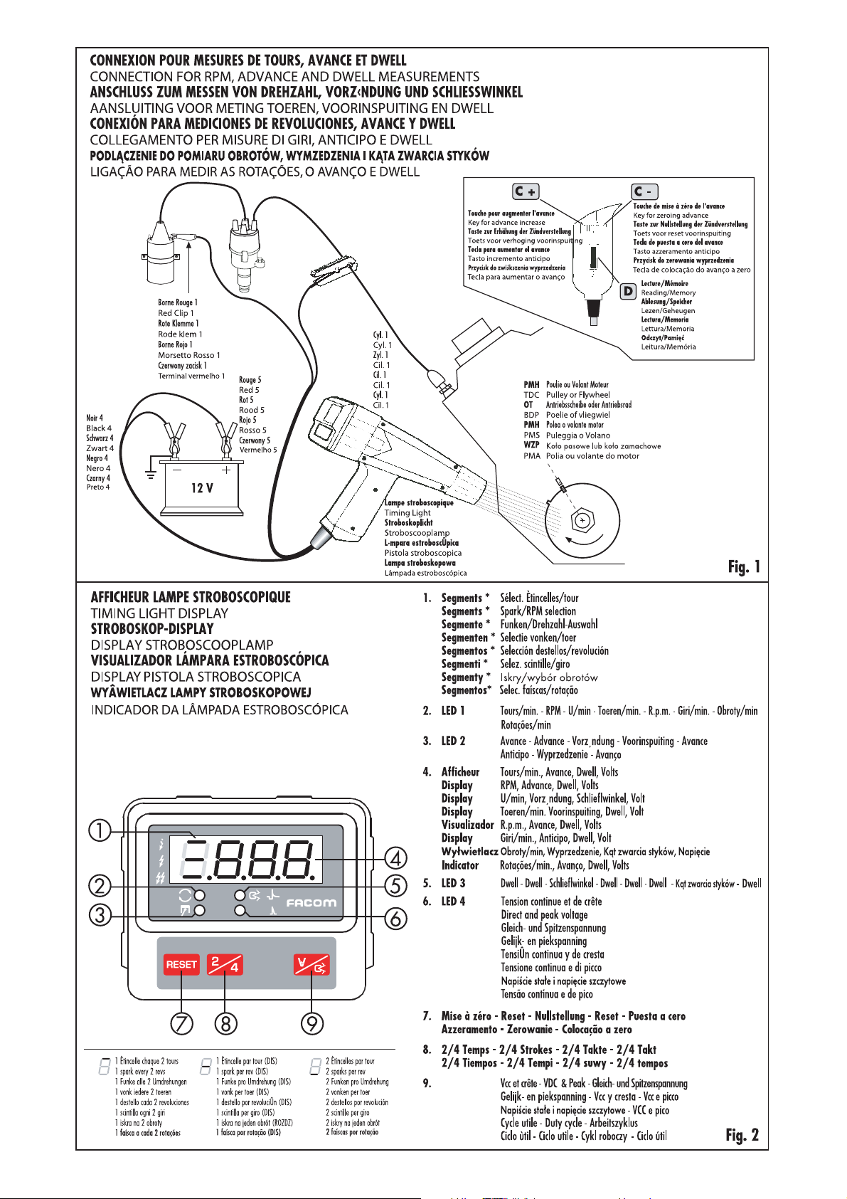
Lampe Stroboscopique
Timing Light
Stroboskoplicht
Stroboscooplamp
Lámpara Estroboscópica
Pistola stroboscopica
Lampa Stroboskopowa
Lâmpada estroboscópica
Notice d’instructions
Instruction manual
Bedienungsanleitung
Gebruiksaawijzing
Guia de instrucciones
Istruzioni per l’utilizzo
Instrukcja obsługi
Manual de instruções
NU-X.730B/0102

Notes
+ ñ
min.
V=
*)
Volt/Dwell
1

FR
1. INTRODUCTION
usures, la consommation de carburant et
l’émission des gaz d’échappement nuisibles.
La lampe stroboscopique X.730 B peut
être utilisée sur moteurs à essence à 4 ou 2
3. PRÉCAUTIONS
temps jusqu’à 2 étincelles par tour.
Les mesures stroboscopiques des tours et
d’avance sont indépendantes du nombre
des cylindres et peuvent être effectuées
en connectant la pince à induction au câble
Pour garantir un fonctionnement prolongé
dans le temps, il est nécessaire d’enrouler
les câbles soigneusement, jamais autour
de la lampe.
bougie du 1er cylindre.
Les tensions continues ou de crête peuvent
4. INSTRUCTIONS POUR L’EMPLOI
être mesurées en connectant la borne
ROUGE 1 au point d’essai.
Les lectures du Dwell des cames des distributeurs d’allumage peuvent être effectuées
en degrés ou pourcentage.
Les mesures en millisecondes du temps
d’injection sur les injecteurs ou du cycle
de travail utile (duty cycle) sur d’autres
actuateurs s’effectuent en connectant la
BORNE ROUGE 1 et la pince à induction au
• Monter la lampe comme illustré dans le
schéma de la Fig. 1.
Un branchement inversé des bornes ROUGE/
NOIRE à la batterie, n’endommage pas la
lampe. Brancher la pince à environ 10 cm
du distributeur avec la fl èche tournée vers la
bougie. Placer les câbles de la lampe loin des
tuyaux d’échappement, parties tournantes
et des câbles haute tension.
câble bougie du cylindre correspondant.
On peut aussi mesurer les tours avec le stroboscope, sans contact et sans appliquer aucun
catadioptre sur la partie tournante.
• Vérifi er que les connexions électriques de
la bobine soient correctes. Des connexions
inversées peuvent causer des lectures instables
et la diminution du rendement du moteur.
2. CONTRÔLES
• Vérifi er que les repères soient bien visibles;
Sans démonter les parties en examen, il
est possible de diagnostiquer les défauts
et les usures:
sinon on peut tracer deux signes en ligne sur
le carter et sur la poulie de l’arbre moteur,
avec le piston du cylindre No. 1 au Point Mort
Haut en phase de compression.
1 - dans le système d’ouverture des contacts;
2 - dans les mécanismes d’expansion centrifugeuse de l’avance;
3 - dans le système de distribution;
• En pressant la touche D, la lampe doit
clignoter régulièrement; des instabilités du
clignotement pourraient être causées par:
4 - dans le système d’avance à dépression;
5 - dans le système de retard à dépression;
6 - dans les capteurs, la batterie et le système de charge.
Un contrôle et un réglage correct des différentes parties décrites ci-dessus permettent
d’optimiser le rendement, de limiter les
- câbles bougie non résistifs;
- décharges entre les pôles de la tête
d’allumeur ou vers la masse dues à saleté
ou humidité;
- dispersions vers la masse ou entre les
câbles à cause du vieillissage ou fi ssures
CARACTÉRISTIQUES TECHNIQUES
LECTURES ECHELLE RÉSOLUTION
– Tours 400÷19.999 tours/min. 1 tour/min.
– Avance stroboscopique 0÷78°/90° (400/465 tours/min.) 0.1°
– Dwell (cycle utile) 0÷ 65 ms 0.1 ms
pour chaque cylindre 0÷100% 0.1%
0÷120° (> 600 tours/min.) 0.1°
– Tension continue 1÷70 Volts 0.1 Volt
– Tension de crête 1÷70 Volts 0.1 Volt
– Compte-tour stroboscopique 60÷6000 tours/min. 1 tour/min.
– Mémoire des lectures 6 s (après le relâchement de la touche D)
– Alimentation 9.5÷15 Volts (9.5÷35 V optionnel)
dans l’isolant;
- usure et distance excessive entre le doigt
de l’allumeur et les pôles ou le contact
central de la tête d’allumeur;
- électrodes de la bougie trop proches ou
avec trop de résidus de carbone;
- tension trop basse sur la bougie à cause de
défauts du système d’allumage;
- lampe stroboscopique trop proche des
câbles des bougies, de l’allumeur ou de
la bobine.
• Contrôler à contre jour que les noyaux de
la pince joignent parfaitement.
Avec un chiffon, enlever les éventuels corps
étrangers, graisse et poussière qui peuvent
s’enfoncer entre les surfaces.
5. CONTROLE DE L’ANGLE DE CAME
• Démarrer le moteur et le faire chauffer
jusqu’à obtenir une rotation régulière au
ralenti.
• Détacher le tube du dépresseur, si indiqué
dans le manuel des données.
• Dans les systèmes avec allumage à rupteur ou transistorisé, le contrôle de l’angle
de came DWELL s’effectue en connectant la
borne ROUGE 1 au négatif bobine.
• Dans les systèmes avec capteur à réluctance, une lecture à zéro indique un capteur
ou le câblage interrompu. Une lecture
très différente de 3÷5 ms est causée par
une distance pôles/capteur différente des
prescriptions, par un module défectueux
ou une résistance de connexion à la masse
supérieure à 0.1. Contrôler le boîtier
électronique, dans le cas où elle commande
le module d’allumage.
• En cas de systèmes à rupteur suivre les
instructions page 4. Si la mesure en degrés
ou pourcentage ne correspond pas aux données du constructeur, la distance des contacts
pourrait être incorrecte, les contacts, les
cames ou l’axe du distributeur usés.
• Porter le moteur à 2000 tours, la variation
ne devrait pas dépasser 3 degrés (en cas de
doutes se rapporter aux caractéristiques
déclarées par le constructeur avant de le
remplacer).
2

FR
Des instabilités supérieures peuvent être
causées par: arbre ou bague du distributeur
endommagés, pivot des contacts consommés, contacts relâchés.
Des variations incorrectes peuvent être
causées par: pivot de la plaque portecontacts consommé ou membrane de la
capsule fi ssurée.
Note : Un angle de fermeture des contacts
élevé donne lieu à une brûlure prématurée
des contacts, un angle de fermeture trop
bas donne lieu à un allumage insuffi sant
et par conséquence une diminution du
rendement du moteur.
Contrôler l’avance après la réparation.
6. CONTRÔLE DU NOMBRE DES
TOURS
• Les lectures jusqu’à 19 990 tours/ min.
s’effectuent avec la pince à induction.
Mesures stroboscopiques jusqu’à 6 000
tours/min. s’effectuent en suivant les
instructions page 4.
• Dans les systèmes à carburateur et dans
quelques uns à injection électronique, régler
le ralenti par l’intermédiaire de la vis spéciale pour un rapport correct air/essence.
7. CONTRÔLE DU RENIFLARD DE L’HUILE
• Le contrôle s’effectue en détachant les tubes
qui vont du carter à la tête du moteur.
En fermant l’extrémité du tube avec un
doigt, on devra observer une diminution de
50 tours ou plus; sinon on doit contrôler qu’il
n’y ait pas d’obstructions des fi ltres ou de
pannes éventuelles des soupapes du conduit.
8. CONTRÔLE DE LA POSITION DES
REPÈRES D’AVANCE
• Si l’on veut limiter le contrôle à la position
des repères, porter l’affi cheur à 00,1 par
l’intermédiaire de la touche C–.
• Porter le moteur au ralenti et, sauf indication différente du constructeur, détacher
le tube du dépresseur.
En pressant la touche D, la lampe doit clignoter. Si le repère de la poulie n’est pas dans
la position correcte, tourner le distributeur.
La même procédure peut être adoptée pour
le contrôle des repères de l’avance centrifuge.
Dans les systèmes avec boîtier électronique,
contrôler le capteur de température du moteur.
9. MESURE D’AVANCE
• Contrôler que le nombre des tours soit
celui indiqué par les données.
• Avec la touche C± porter l’affi cheur à la
valeur de degrés indiqué par les données
techniques; illuminer les repères de PMH
en faisant éventuellement attention à ne
pas les confondre avec d’autres.
Les repères doivent coïncider dans les tolérances admises par le constructeur, sinon
il faut orienter le distributeur ou contrôler
que la chaîne ou la courroie de distribution
n’ait pas sauté une dent.
Dans les systèmes avec boîtier électronique
contrôler le capteur de température moteur.
Note : Pour certains véhicules, les repères de
référence peuvent être mieux illuminés
en tenant la lampe stroboscopique en
position inconfortable pour la lecture.
En ce cas relâcher la touche D quand les
repères sont en ligne, lire la valeur dans
les 6 secondes.
10. MESURE D’AVANCE CENTRIFUGE
• Porter le moteur au régime de tours
indiqué sur les données.
• Avec la touche C± porter l’affi cheur à la
valeur de degrés indiqué sur les données;
les repères de PMH sur le carter et sur la
poulie de l’arbre moteur devront coïncider.
Si l’erreur est excessive, contrôler le capteur
de température du moteur.
Si le repère oscille trop, bouge irrégulièrement pendant les accélérations, contrôler
que la courroie de distribution ne soit pas
détendue ou usée.
Dans les systèmes à rupteur contrôler le
mécanisme centrifuge, les ressorts, les
pivots ou l’axe du distributeur.
Note : Une avance centrifuge défectueuse
donne lieu à un manque de reprise et
à des “trous” de puissance à certains
régimes.
11. CONTRÔLE DE L’AVANCE À
DÉPRESSION
• Quand on introduit le tube de dépression,
on devra remarquer une augmentation de
l’avance, qui peut être mesurée en reportant les repères de PMH en ligne.
Si dans les systèmes à rupteur, il n’y a pas de
variation ou si elle est trop hors des limites,
on doit contrôler la membrane et la plaque
porte- contacts.
Note : Dans les systèmes d’allumage/
injection commandés par boîtier
électronique, si l’avance à dépression
ne correspond pas aux spécifications
du constructeur, contrôler le capteur de
dépression.
12. CONTRÔLE DU RETARD EN
ACCÉLÉRATION
Le contrôle peut être fait sur les moteurs
pourvus de ce dispositif.
• Porter l’affi cheur à 00,1 avec la touche
C±. Quand on introduit le tube du retard à
dépression pendant les accélérations, on devra remarquer une diminution temporaire
de l’avance.
En cas de variations anormales, contrôler
les organes mécaniques concernés ou le
capteur de dépression dans les boîtiers
électroniques.
13. MESURES DE TENSION
En connectant la borne ROUGE 1 au point
de mesure on peut contrôler la baisse
de tension de batterie au démarrage et
la charge de l’alternateur, variations de
tension sur les capteurs de température,
potentiomètre d’accélérateur, tensions de
crête des capteurs inductifs de PMH et tours,
signaux des boîtiers électroniques envoyés
au module d’allumage.
14. RESET
Si l’affi cheur de la lampe présente des anomalies pendant le branchement des bornes
ROUGE/NOIRE d’alimentation ou pendant
le fonctionnement, éloigner la lampe
des éventuels brouillages (câbles bougie,
distributeurs, alternateurs) et appuyer sur
la touche RESET.
3
FR
PROGRAMMATION DES MESURES
INTRODUCTION : Après la connexion à la batterie, la lampe stroboscopique se dispose automati-
quement pour la mesure de Tours, Avance, Tension, 1 étincelle tous les 2 tours (système d’allumage
à distributeur), moteur à 4 cylindres et à 4 temps.
Pour changer cette programmation, procéder comme suit :
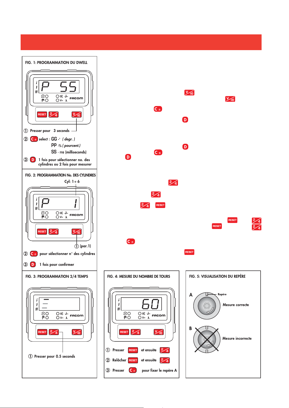
SÉLECTION DU DWELL : En pressant la touche , l’appareil se dispose pour la mesure du
Dwell en millisecondes. Pour sélectionner d’autres lectures, tenir la touche pressée jusqu’à
ce que sur l’affi cheur apparaîsse l’affi chage fi gure 1.
Appuyer ensuite sur la touche pour sélectionner les mesures en degrés (GG), pourcentage
(PP) ou retourner aux millisecondes (SS).
Après la sélection appuyer une fois sur la touche pour sélectionner le nombre des cylindres ou
deux fois pour procéder à la mesure.
SÉLECTION DU NOMBRE DE CYLINDRES : Permet de mesurer les temps d’injection ou de
charge de la bobine du cylindre en examen. En cas de moteurs avec un nombre de cylindres
différent de 4, après avoir appuyé sur la touche pour la première fois, apparaîtra l’affi chage
de fi gure 2. Presser la touche pour sélectionner le nombre de cylindres. Appuyer une fois
sur la touche pour confi rmer.
L’appareil sera prêt pour la mesure.
SÉLECTION DU NOMBRE D’ÉTINCELLES PAR TOUR : L’appareil est programmé pour une
étincelle tous les deux tours (moteurs à 4 temps avec distributeur ou bobines par cylindre) comme
indiqué en fi g. 3, appuyer sur la touche pour sélectionner une étincelle par tour (moteurs à
2 temps ou 4 temps avec systèmes DIS).
Appuyer encore sur la touche pour déplacer la ligne en correspondance du symbole de deux
étincelles par tour (moteurs à deux cylindres à 2 temps avec système DIS). L’appareil sera prêt pour
la mesure. Appuyer sur ou pour reporter l’appareil à une étincelle tous les deux tours.
MESURE STROBOSCOPIQUE DU NOMBRE DES TOURS : Avec un bâton de craie, tirer un
trait blanc sur le corps tournant. Programmer l’appareil en pressant la touche et après
, tenir pressés les deux pour quelques instants. Relâcher la touche et tenir la touche
pressée jusqu’à ce que 60 n’apparaît. Le strobotesteur clignotera automatiquement.
Augmenter le nombre de tours sur l’affi cheur jusqu’à 6000 max. (ou le diminuer si nécessaire)
avec la touche . Lire le nombre de tours au moment où la fréquence des fl ash permet d’arrêter
l’image (individuelle) du repère (fi g. 5A).
Pour retourner aux autres fonctions, appuyer sur
4

EN
1. GENERAL INFORMATION
The timing light X.730 B can be used on 2 or
4 stroke petrol engines with up to 2 sparks
per revolution. Stroboscopic RPM and ad-
3. PRECAUTIONS
In order to prolong the lifetime of the unit,
it is necessary to softly coil the cables but
never wrap them around the timing light.
vance measurements are independent from
the number of cylinders and can be carried
out by connecting the inductive clamp to the
spark cable of the No.1 cylinder.
DC or peak voltages can be measured by
connecting the RED 1 clip to the test point.
Dwell of each distributors’ camshafts can be
measured both in degrees or in percentage.
Injection time or duty cycle measurements
in milliseconds of injectors or other actuators
can be made by connecting the RED 1 CLIP
and the inductive clamp to the spark cable
of the relevant cylinder.
RPM measurements can be carried out
by the stroboscope, without contact and
without sticking any refl ecting tapes to the
rotating part.
2. CHECKS
4. OPERATING INSTRUCTIONS
• Connect the timing light as shown in Fig.
1.A reversed connection to battery of the
RED/BLACK clips does not cause damages
to the timing light.
Mount the clamp at about 10 cm from the
distributor, with the arrow pointing towards
the spark plug.
Make sure the cables are far from exhaust
pipes, rotating parts and high voltage leads.
• Check that the coil’s electrical connections
are correct. Reversed connections can cause
reading unsteadiness and decrease the
engine performance.
• Check that the timing marks can be seen
clearly; bring otherwise the piston of the
It is possible to diagnose faults and wears
without disassembling the part concerned:
No.1 cylinder at TDC in compression stroke,
and trace with a white chalk two signs in line
on the crankcase and the crankshaft pulley.
1 - in the contact breaker system;
2- in the centrifugal advance mechanism;
3 - in the timing system;
4 - in the vacuum advance system;
• By pressing the D key, the strobe light
should fl ash regularly; an irregular fl ashing
could be caused by :
5 - in the vacuum retard system;
6 - in the battery and charging system.
- non-resistive spark cables;
- discharges between cap poles or to ground
A check and a correct adjusting of the different parts described above allow to optimize
the engine performance, reduce wears, fuel
consumption and harmful gas emissions.
due to dirt or moisture;
- leakage to ground or between cables due
to ageing or cracks in the insulating sheath;
- wear or excessive gap between rotor arm
and poles or cap’s central contact;
- too small spark gap or spark electrodes
with too much carbon residues;
TECHNICAL FEATURES
READING SCALE RESOLUTION
– RPM 400÷19.999 rpm 1 rpm
– Stroboscopic advance 0÷78°/90° (400/465 rpm) 0.1°
– DWELL (for each cylinder) 0÷ 65 ms 0.1 ms
0÷100% 0.1%
0÷120° (> 600 rpm) 0.1°
– DC Voltage 1÷70 Volts 0.1 Volt
– Peak Voltage 1÷70 Volts 0.1 Volt
– Stroboscopic RPM counter 60÷6000 rpm 1 rpm
– Memory of readings 6 s (from key D release)
– Power supply 9.5÷15 Volts (9.5÷35 V optional)
- too low voltage on the spark plug due to
faults in the ignition system;
- timing light too near to spark cables,
distributor or ignition coil.
• Check against the light that the clamp’s
cores match completely. With a cloth,
remove possible grease and dust.
5. CHECKING THE DWELL ANGLE
• Start the engine and make it warm till
reaching a regular rotation at idle.
• Disconnect the vacuum tube, if specifi ed
in the data manual.
• In breaker points or transistorized ignition
systems, the Dwell angle is checked by
connecting the RED 1 clip to coil negative.
• In some transistorized systems, a zero
reading means an interrupted reluctor or
wiring. If the reading is very different from
3÷5 ms, the causes can be: a wrong distance
between poles and reluctor, a faulty module
or a resistance of the ground connection
higher than 0.1 Ohm.
Check the ECU, in case it should directly
drive the ignition coil.
• In case of breaker points systems follow
the instructions page 7 to check that the
measurement in degrees or percentage
corresponds to the manufacturer’s data.
Readings out of tolerance can be due to:
wrong distance between contacts, damages
to the base plate or the contacts, worn
camshaft and distributor shaft .
• Bring the engine to 2000 RPM, variation
should not be more than 3 degrees (some
distributors have higher variations, it is
therefore necessary to check the features
declared by the manufacturer before
changing it).
Higher variations can be due to the same
causes described in the previous chapter,
loose contacts, used contacts’ pivot.
In case of an excessive variation when
connecting the vacuum tube, the pivot post
of the base plate could be damaged.
5

EN
No variations or wrong variations could
be caused by: diaphragm of the vacuum
advance variator cracked.
Note : In breaker points systems, an
excessive wear of the distributor’s parts
causes abnormal advance variations and
a decreased engine performance. A too
low Dwell angle causes an insuffi cient
ignition; a too high Dwell angle causes a
premature burning of contacts. Remember
to check the advance after repair.
6. CHECKING THE RPM NUMBER
• Reading up to 19 990 RPM can be made
through the inductive clamp.
Direct measurements up to 6000 RPM are
possible with the stroboscope. In this case
refer to page 7.
• In carburettor systems and in some early
electronic injection systems, adjust the advance through the special screw for a correct
air/petrol mixture until obtaining a regular
engine rotation.
Note : A perfect idle adjustment limits
fuel consumption, emission of harmful
exhaust gases and avoids engine stops.
7. CHECKING BREATHER PIPES
• The check is made by disconnecting the
tubes that go from the crankcase to the
engine head or to the carburettor. By closing
the top of the tube with a fi nger, a drop of
50 or more RPM should occur. If not, check
that there are no fi lter occlusions or possible
damages of the pipe’s valves.
8. CHECKING THE MECHANICAL
POSITION OF TIMING MARKS
• To check only the timing marks’ position,
bring the display to 00,1 through the C– key.
• Bring the engine to idle and disconnect the
vacuum tube or observe the instructions of
the manufacturer.
By pressing the D key, the timing light
should fl ash.
If the timing mark is too far from the correct
position, rotate the distributor or check
that the distribution belt has not jumped a
cog. The same procedure may be used for
checking the marks of centrifugal advance.
In systems with ECU, check the engine
temperature sensor.
9. ADVANCE MEASUREMENT
• Check that the RPM number is the same
shown in the manufacturer’s data.
• Press the C± key until the display shows
the number of degrees indicated in the
manufacturer’s data.
Lighten the TDC marks on the pulley and
crankcase taking care not to confuse them
with the other ones.
Check that the error in the alignment of
TDC marks is within the tolerances foreseen
by the manufacturer, otherwise turn the
distributor. In ECU systems, check that the
timing belt has not jumped a cog or that
the engine temperature sensor is not faulty.
• If the TDC mark swings too much check
the distribution belt and the distributor
mechanisms in point systems.
Note : In some vehicles, reference marks
can be better lightened by keeping the
timing light in an uncomfortable position
for the reading. In this case store the
reading when the marks are aligned by
releasing the key D, then read the value
within 6 seconds.
10. CENTRIFUGAL ADVANCE
MEASUREMENT
• Run the engine to the speed indicated in
the data manual.
• Press the C± key until the display shows
the number of degrees indicated in the
data manual or in manufacturer’s data;
TDC marks on the crankcase and on the
crankshaft pulley should be in line.
If the error is excessive, check the engine
temperature sensor in ECU systems; if the
mark swings too much, or moves irregularly
during accelerations, check that the timing
belt is not loose.
In points systems check the contact spring;
the centrifugal mechanism could otherwise
be worn as well as the pivots or the distri-
butor shaft.
Note : A faulty centrifugal timing can result
in lack of pick-up and fl at points in engine
power at certain engine speeds.
11. CHECKING THE VACUUM
ADVANCE
• By connecting the vacuum tube, advance
should increase. It can be measured by
bringing TDC marks in line.
In points systems: if there is no variation or
if the advance is too much out of tolerances,
the diaphragm and the baseplate should be
checked.
Note : In ECU controlled ignition/injection
systems, if the advance caused by the
vacuum device does not correspond
to the manufacturer’s specifi cations, it
can be due to a wrong operation of the
vacuum sensor.
12. CHECKING THE ACCELERATION
RETARD
This check can be made in engines provided
with this device.
• Press the C± key to bring the display to
00,1. By connecting the vacuum retard tube
during sudden accelerations, the advance
should momentarily decrease.
In case of anomalous variations, check the
diaphragm or other mechanical parts.
13. VOLTAGE MEASUREMENTS
Measurements of direct battery voltage at
cranking, alternator’s charge, voltage variations on temperature sensors, throttle potentiometer, peak voltage of TDC inductive
sensors, RPM sensors or the control signal
sent by the ECU to the ignition modules can
be made by connecting the RED 1 clip to the
signal contact.
14. RESET
If the timing light display should show faults
while connecting the RED/ BLACK power
clips or during operation, take the timing
light away from possible noise sources
(spark cables, distributors, alternators) and
press RESET.
6
EN
MEASUREMENTS SETUP
PREFACE : After connection to the battery, the strobotester is automatically set for the measu-
rement of RPM, Advance, Voltage, 1 spark per 2 revs (distributor ignition system), 4-cylinder,
4-stroke engines.
To change the default settings, proceed as follows :
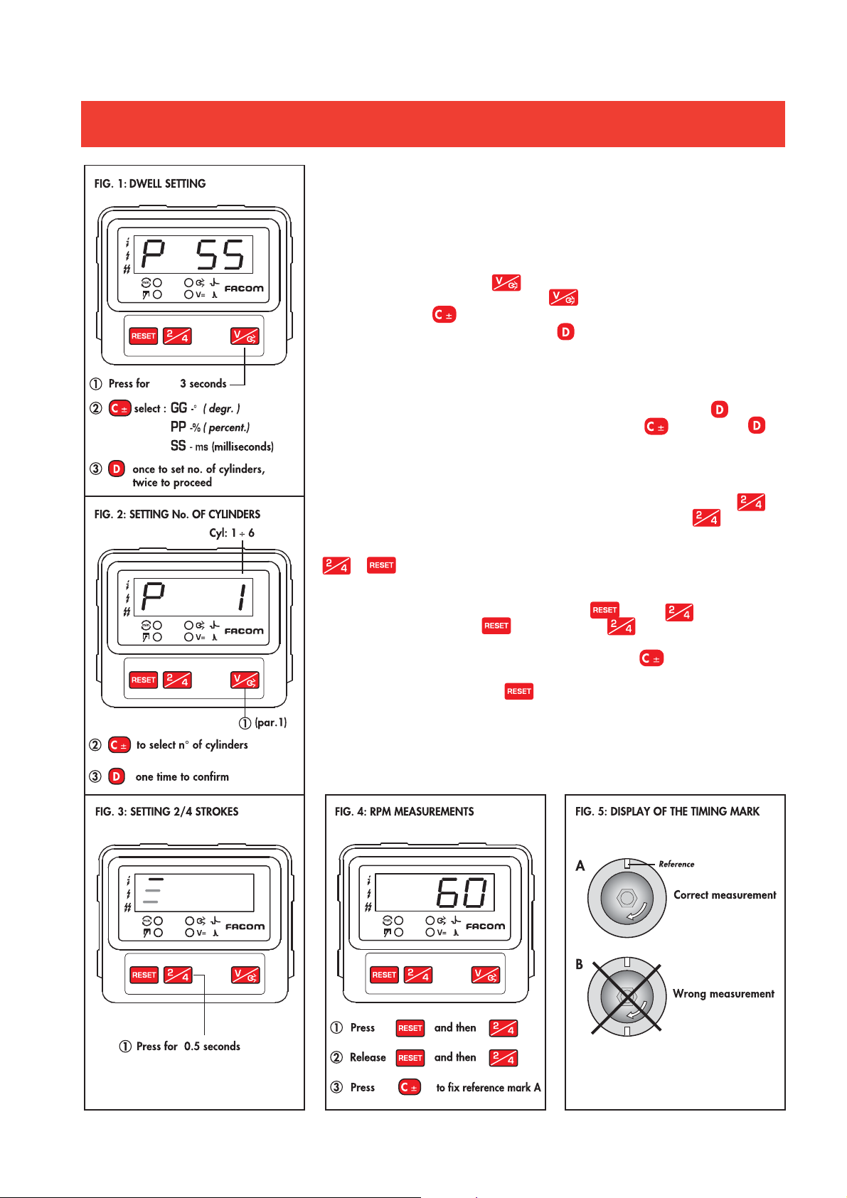
DWELL SELECTION : By pressing key, the unit sets for measurements in milliseconds. The
other readings can be selected by keeping the key pressed until the display shown in fi g.
1 appears. Then press key to select measurements in degrees (GG), in percentage (PP) or
return to milliseconds (SS). After selection, press key once to choose the number of cylinders
or twice to proceed with the measurements.
SELECTION OF NUMBER OF CYLINDERS : Allows to carry out measurements of injection time
or ignition coil charge relevant to the cylinder under test.
In case of engines that do not have 4 cylinders, after the fi rst pressing of the key , the display
shown in fi g. 2 will appear. Select the number of cylinders through key. Press once key
to confi rm.
The strobotester is now ready for measurements.
SELECTION OF NUMBER OF SPARKS PER REV. : The unit is set for one spark per two revs
(4-stroke engines with distributor and coil per plug systems) as shown in fi g. 3. Press key
to select one spark per rev (2 or 4 stroke engines with DIS systems). Press key again to
shift the line, appearing on the left side of the display, beside the symbol of two sparks per rev
(2-cylinder and 2-stroke engines with DIS system). The unit is now ready for measurements. Press
or key to return to one spark per two revs.
STROBOSCOPIC MEASUREMENT OF THE RPM NUMBER : With a piece of chalk trace a
white mark on the rotating body. Set the unit by pressing key then key and keep them
pressed for a while. Release the key while keeping key pressed, until 60 appears
(see fi g 4). The strobotester will blink automatically. Increase the RPM number on the display up
to a maximum of 6000 (or decrease it if necessary) through the key. Read the RPM when
the fl ash frequency allows to stop the (single) image of the white mark (fi g. 5A).
To return to normal reading press the key.
7
 Loading...