

Facom E.S401, E.S404 Instruction Manual

EN
1 2 3 4 5
6
7
A
Dear Customers,
Thank you for purchasing our digital torque
screwdriver
. This manual will help
you to use the many features of your new digital torque
screwdriver
. Before
operating the torque
screwdriver
, please read this manual completely, and keep
it nearby for future reference
MAIN FEATURES
• Digital torque value readout
• +/- 2 % or +/-3 % accuracy
• CW and CCW operation
• Peak hold and track mode selectable
• Buzzer and LED indicator for the 9 pre-settable target torques
• Engineering units (cN-m, in-lb, kg-cm) selectable
• 250 data memory for recall and joint torque auditing
• Auto Sleep after about 5 minutes idle
• Both AAA and rechargeable batteries are compatible
• Communication functions
NAMES AND FUNCTIONS OF PARTS A
1. Autolock bit holder 7. Buttons
2. Communication Port 8. Torque Value
3. LCD Display 9. Units
4. LED Indicator 10. Peak / Track mode
5. Anti-slip handle 11. Memory number
6. Battery Cover 12. Clear Button
8
9
10
11
12
E.S401
E.S404
Accuracy *1 CW ±2% CCW ±3%
Data memory size 250
PC Connectivity *2 Yes / USB
Pre-setting No. 9 sets
Bright LED
2 LEDs / 1 Red+1 Green
Operation Mode Peak Hold / Track
Unit Selection
cN-m, in-lb, kg-cm
Head Type Autolock bit holder
Button 5
Battery*3
AAA x 1
Operating Tempe-
rature
-10°C ➜ 60°C
Storage Temperature
-20°C ➜ 70°C
Humidity Up to 90% non-condensing
Drop Test 1 m
Vibration Test *4 10 G
Environmental test *5 Pass
Electromagnetic
compatibility test *6
Pass
SPECIFICATIONS
Note:
*1: The accuracy of the readout is guaranteed from 20% to 100% of
maximum range + /- 1 increment. The torque accuracy is a typical value.
Calibration point is on the rubber grip. For keeping the accuracy, calibrate the
screwdriver for a constant period time (1 year).
*2:
Use a special designed USB cable (accessory) to upload record data to PC.
*3: Use one AAA batteries (Test condition: Toshiba carbon-zinc R6UG
battery)
*4: Horizontal and vertical test
*5: Environmental test:
a. Dry heat e. Impact (shock)
b. Cold f. Vibration
c. Damp heat g. Drop
d. Change of temperature
*6: Electromagnetic compatibility test:
a. Electrostatic discharge immunity (ESD)
b. Radiated susceptibility
c. Radiated emission
Digital torque screwdriver
Instruction manual
E.S401
E.S404
BELGIQUE Stanley Black&Decker Belgium BVBA (FACOM)
LUXEMBOURG Egide Walschaertstraat 16
2800 Mechelen
Belgium
T +32 (0)15 47 39 30
Facom.Belgium@sbdinc.com
DANMARK FACOM Nordic
FINLAND Flöjelbergsgatan 1c
ISLAND SE-431 35 Mölndal, Sweden
NORGE Box 94, SE-431 22 Mölndal, Sweden
SVERIGE Tel. +45 7020 1510
Tel. +46 (0)31 68 60 60
Tel. +47 22 90 99 10
Tel. +358 (0)10 400 4333
Facom-Nordic@sbdinc.com
DEUTSCHLAND
STANLEY BLACK & DECKER Deutschland GmbH
Black & Decker Str. 40
65510 Idstein
Tel.: +49 (0) 6126 21 2922 / Fax +49 (0) 6126 21 21114
verkaufde.facom@sbdinc.com
www.facom.com
ESPAÑA FACOM HERRAMIENTAS, S.R.L.U.
C/Luis 1°, n° 60 - Nave 95 - 2ª Pta
Polígono Industrial de Vallecas - 28031 MADRID
Tel: +34 91 778 21 13 / Fax: +34 91 778 27 53
facom@facomherramientas.com
PORTUGAL FACOM S.A.S
6/8 rue Gustave Eiffel - BP 99
91423 MORANGIS CEDEX - France
Tel: 01 64 54 45 45 / Fax: 01 69 09 60 93
ITALIA SWK UTENSILERIE S.R.L.
Sede Operativa : Via Volta 3
21020 MONVALLE (VA) - ITALIA
Tel: 0332 790326 / Fax: 0332 790307
LATIN FACOM S.L.A.
AMERICA 9786 Premier Parkway
Miramar, Florida 33025 USA
Tel: +1 954 624 1110 / Fax: +1 954 624 1152
NETHERLANDS
Stanley Black&Decker Netherlands (FACOM)
POSTBUS 83
6120 AB BORN
NEDERLAND
Tél: 0800 236 236 2 / Fax: 0800 237 60 20
Facom.Netherlands@sbdinc.com
ASIA
The Stanleyworks( Shanghai) Co.,
Ltd 8/F,Lujiazui Fund Tower No.101,
Zhulin Road PuDong District
Shanghai, 20122,China
Tel: 8621-6162 1858 / Fax: 8621-5080 5101
SUISSE
Stanley Works Europe Gmbh
Ringstrasse 14
CH - 8600 DÜBENDORF
Tel: 00 41 44 755 60 70 / Fax: 00 41 44 755 70 67
ÖSTERREICH STANLEY BLACK & DECKER Austria GmbH
Oberlaaerstrasse 248
A-1230 Wien
Tel.: +43 (0) 1 66116-0
Fax.: +43 (0) 1 66116-613
verkaufat.sbd@sbdinc.com
www.facom.at
UNITED KINGDOM
Stanley Black & Decker UK Limited
EIRE 3 Europa Court
Shef eld Business Park
Shef eld, S9 1XE
Tél. +44 1142 917266
Fax +44 1142 917131
www.facom.com
ČESKÁ REP.
Stanley Black & Decker
SLOVAKIA Czech Republic s.r.o.
Türkova 5b
149 00 Praha 4 - Chodov
Tel.: +420 261 009 780
Fax. +420 261 009 784
POLSKA
Stanley Black & Decker Polska Sp. z o.o
ul. Postepu 21D, 02-676 Warszawa
Tel: +48 22 46 42 700
Fax: +48 22 46 42 701
FRANCE ET
FACOM S.A.S
INTERNATIONALE 6/8 rue Gustave Eiffel - BP 99
91423 MORANGIS CEDEX - France
Tel: 01 64 54 45 45
Fax: 01 69 09 60 93
www.facom.com
En France, pour tous renseignements techniques sur l’outillage à
main, téléphonez au : 01 64 54 45 14
NU-en ES401-E.S404_0615
N.m
min. max.
in.lb
min. max.
kg.cm
mini. max.
mm g
E.S401
0,1 ➜
1
0,9
➜ 8,8 1,0
➜
10,2
1/4’’ (6,35 mm)
215 630
E.S404
0,4 ➜ 4 3,5 ➜
35,4 4,0 ➜ 40,8
SPECIFICATIONS
ISO 6789 Model 2 Class D Screwdriver precision : ± 2% ± 3%
ACCESSORIES
3,2 ➔ 14 mm
1 (6,35mm 3 ➔ 8 0 ➔ 4 0 ➔ 4 6 ➔ 40 1,5 ➔ 10 mm ECR 3/16 ➔ 9/16’’
1/8 ➔ 1/4"
Series No ES (mm) EP (N°) ED (N°) EX (N°) ET R
+
+
E.S404 - KIT Plugs KIT
E.S404 - USB USB cable
B
SPARE:
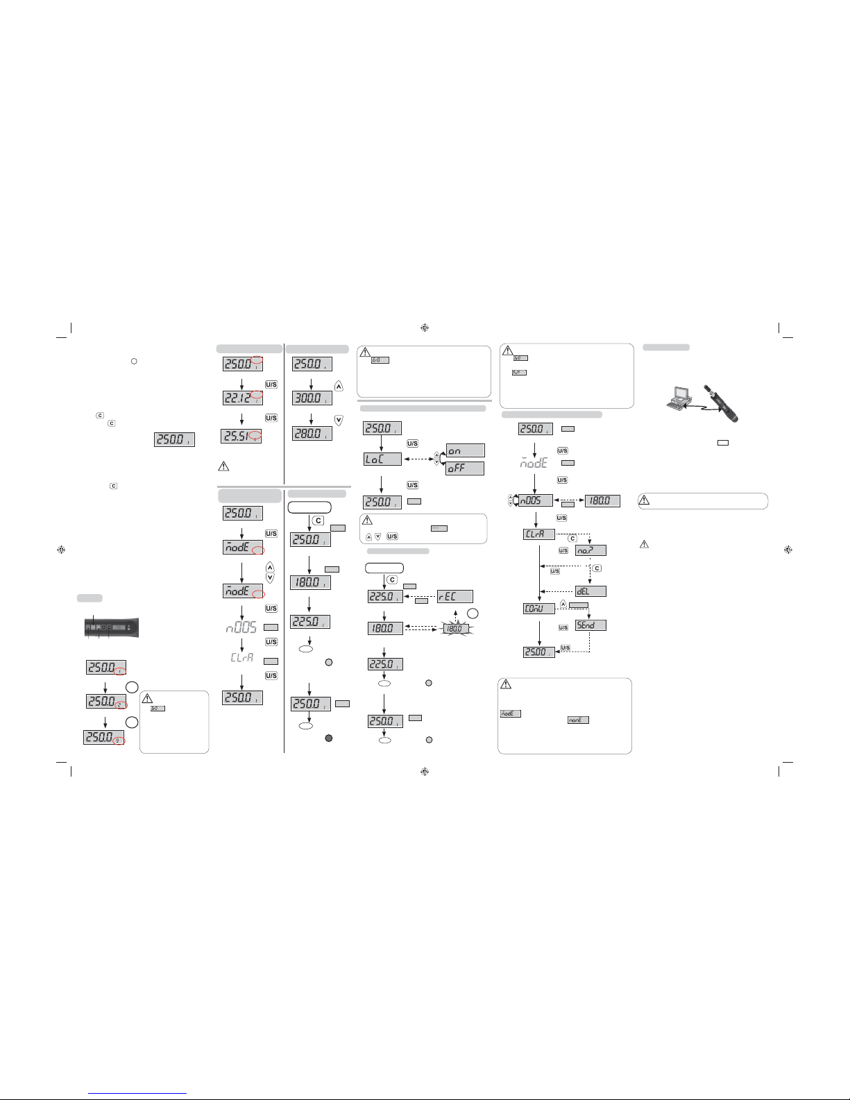
CONNECTING COMMUNICATION CABLE
• Connect the accessory cable between the USB COM port of PC and
screwdriver.
UPLOADING RECORD DATA
• Make sure the connection between PC and screwdriver is normal.
• Change the screwdriver operation mode to “Send”. (Refer to “Peak Hold
Mode Recorded Value Review ” section)
• Use PC to start the uploader program.
• In uploader program, fi rst select the correct COM port No.
• Next, select the fi le path to save the uploaded data.
• Finally, press “upload” button to transmit the torque records to PC.
• The uploaded data is then shown on the column and saved in the *.csv fi le.
Use Microsoft Excel to view *.csv fi le.
CAUTIONS:
Refer to the uploader program user guide for the detail operations
.
MAINTENANCE AND STORAGE
ATTENTION:
One-year periodic recalibration is necessary to maintain accuracy.
Please contact your local dealer for calibrations.
CAUTION:
1. Over-torque (110% of Max. torque range) could cause breakage or lose
accuracy.
2. Do not shake violently or drop screwdriver.
3. Do not use this screwdriver as a hammer.
4. Do not leave this screwdriver in any place exposed to excessive heat,
humidity, or direct sunlight.
5. Do not use this apparatus in water.(not waterproof)
6. If the screwdriver gets wet, wipe it with a dry towel as soon as possible.
The salt in seawater can be especially damaging.
7. Do not use organic solvents, such as alcohol or paint thinner when
cleaning the screwdriver.
8. Keep this screwdriver away from magnets.
9.
Do not expose this
screwdriver
to dust or sand as this could cause serious
damage.
10. Do not apply excessive force to the LCD panel.
11. Apply torque slowly and graspe the center of the handle. Do not apply
load to the end of handle.
12. When checking the accuracy or calibration, please use the bit head
packed inside the blow mold case.
BATTERY MAINTENANCE
1. When the screwdriver is not used for an extended period of time, remove
the battery.
2. Keep a spare battery on hand when going on a long trip or to cold areas.
3. Sweat, oil and water can prevent a battery’s terminal from making
electrical contact. To avoid this, wipe both terminals before loading a battery.
4. Dispose of batteries in a designated disposal area. Do not throw batteries
into a fi re.
BEFORE USING THE SCREWDRIVER
BATTERY INSTALLATION B
• Remove the battery cover.
• Insert one AAA batterie matching the -/+ polarities of the battery to
the battery compartment.
• Put on the battery cap and fasten it tightly according to the following
fi gures.
POWER ON AND RESETTING THE SCREWDRIVER
• Press to power on the digital torque screwdriver.
•
Usually press to reset the digital torque screwdriver before using it.
ATTENTION:
If an external force is applied to the torque screwdriver during power-on/
reset or wake up period, an initial torque offset will exist in the memory.
ACTIVATION DURING SLEEP MODE
• The screwdriver will auto sleep after about 5 minutes idle for power
saving. Press
to wake up the screwdriver again.
CAUTIONS:
During communication period (Send appears), the sleep function is disabled.
RESETTING THE SCREWDRIVER
• If the screwdriver does not function normally, loosen the cap battery
and tighten it to re-start.
SET UP
1 . Power On/Clear
2 . Unit Selection/Setting
3 .
Adjust torque value
4 . Pre-Setting No.
STEP 1: PRE-SETTING NO.
Note:
1.If is appeared, that
means this screwdriver has ever
been applied more than 110% of
maximum torque.
2.The maximum capacity for
“Pre-setting No.” is 9 sets.
3.
The “Pre-Setting No.” is in sequential.
STEP 2: UNIT SELECTION
c.Nm
M
T
2
41 3
c.Nm
M
T
Pre-setting: M1
cN.m
M
T
Press
M
Press
Pre-setting: M2
Pre-setting: M9
M
cN.m
M
T
c.Nm
M
T
Pre-setting: Unit: cN.m
in.lb
M
T
Press
Press
Pre-setting: Unit: in.lb
kg.cm
M
T
Pre-setting: Unit: kg.cm
STEP 3: SET TORQUE VALUE
cN.m
M
T
Pre-setting Torque Value
cN.m
M
T
Press
Press
cN.m
M
T
Increase Max. Torque Value
Decrease Max. Torque Value
Note:
1.The “Unit Selection” is in sequential.
STEP 4: PEAK HOLD (P) /
TRACK MODE SELECTION (T)
c.Nm
M
T
Track Mode
T
Long Press
P
Set Peak/Track mode
Press
Record No.
Press
for selection
Set Peak/Track mode
Press
Clear Record
Press
cN.m
M
P
Peak Hold Mode
*Note 1
*Note 1
TRACK MODE OPERATION
c.Nm
M
T
Max. Target Value
cN.m
M
T
((...((... ...))...))
c.Nm
M
T
START
(system initial)
*Note 1
Apply torque
*Note 2
Current Torque Value
Reach 90% of
Target Torque
cN.m
M
PT
Current Torque Value
((...((... ...))...))
Buzzer
Green LED
Reach 90% of Target Torque
Approach
Max. Target
Value
(((((((( ))))))))
(((((((( )))))))
Buzzer
Red LED
Reach Target Torque
Note:
1. If
is appeared, that means this screwdriver has ever been
applied over than 110% of maximum Torque.
2. The green LED will be on for 90% of target Torque.
3. When reaching the setting Target Torque, the green and the red light
will be on at the same time.
*Note 3
Note:
1. If is appeared, that means this screwdriver has ever been
applied over than 110% of maximum torque.
2. If is appeared, that means the screwdriver’s memory is full
and the next value record can not be written in. Please refer the “Peak
Hold Mode Recorded Value Review” section to clear the momory data.
3. When reaching the setting Target Torque, the green and the red light
will be on at the same time.
PEAK HOLD MODE RECORDED VALUE REVIEW
Note:
1. The “Peak Hold” mode recorded value review also can be operated in
“Track” mode operation.
2. If you operate in the “Peak Hold” mode, the display will show
P
and please go to next step.
3. If the record is empty, it will show .
4. This function is not supported on all type of models.
5. Communication mode is for uploading record data to PC.
6. Communication mode is also for calibration of screwdriver. Please
contact your local dealer for more information.
COMMUNICATION
cN.m
M
P
Peak Hold/Track Mode
*Note 1
Long Press
Record Value
Set Peak/Track Mode
Auto Change
Record No.
*Note 2
Press
*Note 3
cN.m
Press
Record Value
PEAK HOLD MODE OPERATION
cN.m
M
P
Max. Target Value
cN.m
P
((...((... ...))...))
START
(system initial)
*Note 1
Apply torque
Current Max. Value
(Peak Hold)
cN.m
M
P
((...((... ...))...))
Buzzer
Green LED
Reach 90% of Target Torque
Released
Apply torque
cN.m
P
M
Recording
Flashing
*Note 2
Reach
Target Torque
cN.m
M
P
((((((( )))))))
((((((( ))))))))
Buzzer
Red LED
Reach
Target Torque
*Note 3
Reach 90% of Target Torque
cN.m
M
P
Long Press
KEY LOCK
Lock on/off selection
Press
cN.m
M
P
Auto Change
*Note
Note:
If ‘‘LoC on’’ is set, the display will show
while pressing
, ,
(Clear)
Clear Record
Press
No
Yes
Deleted
(give up)
Communication
*Note 4, 5, 6
Press
N.m
M
P
Peak Hold/Track Mode
(Exit)
Twice
 Loading...