

Page 1
712
Notice d'instructions
Instruction manual
Bedienungsanleitung
Gebruiksaanwijzing
Guia de instrucciones
Istruzioni per l'utilizzo
Instrukcja obs∏ugi
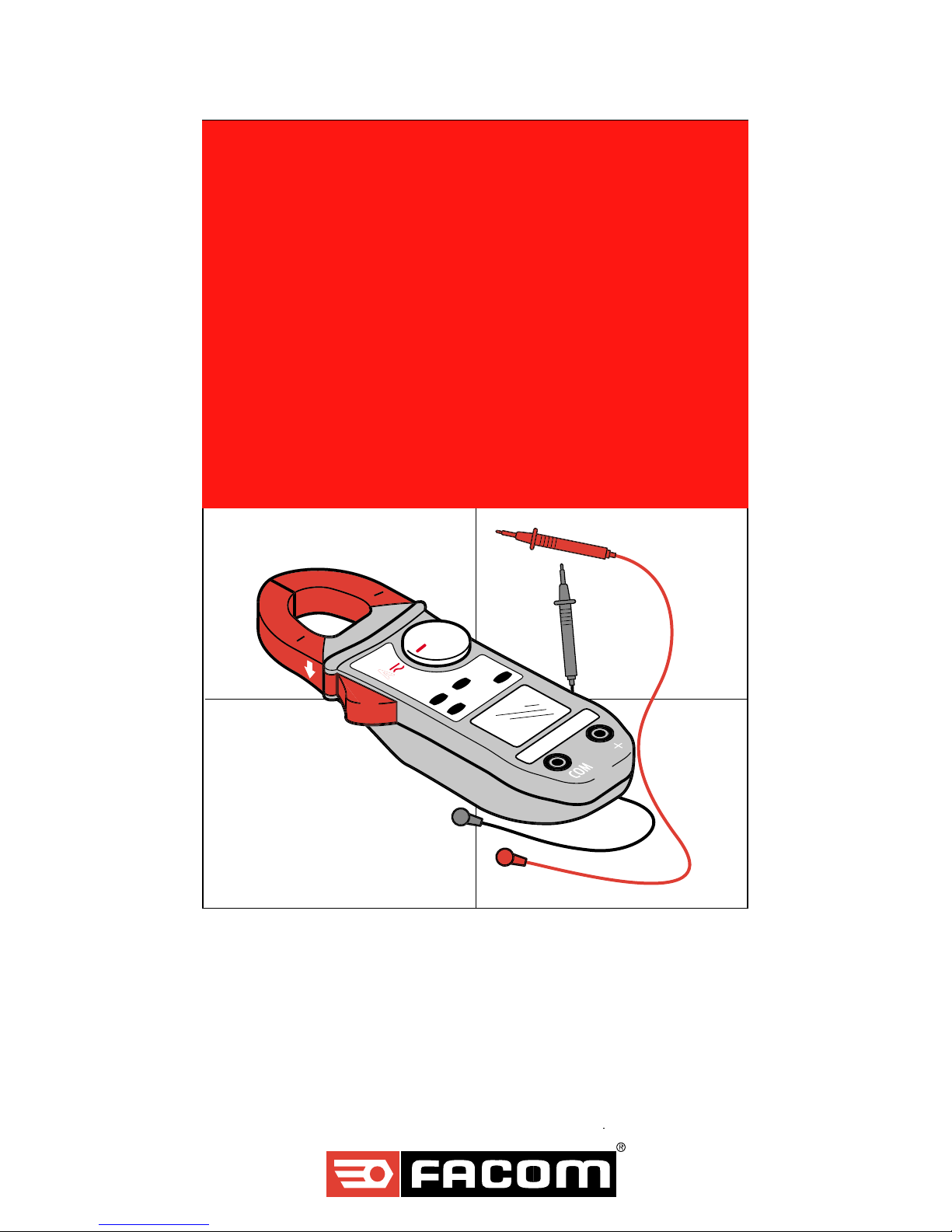
NU-712/1200
■ Contrôleur multifonctions
■ Multi-function tester
■ Multifunktions-Prüfgerät
■ Multi-functie tester
■ Controlador multifunciones
■ Tester Multifunzione
■ Miernik wielofunkcyjny
Page 2

2
Sommaire Page
Sécurité 4
Caractéristiques Techniques 4
Commutateur des 5 fonctions 5
Boutons des fonctions complémentaires 5
Combinaisons des touches 6
Lecture de l'afficheur 6
Branchement des fils sur le contrôleur 6
Mesure des tensions (Voltmètre) 7
Mesure des résistances et de continuité (Ohmmètre) 8
Mesure des diodes (Diodemètre) 9
Mesure des intensités (Ampèremètre) 10
Mesure de température 10 -11
Pièces détachées 12
Contents Page
Safety 13
Specifications 13
5 position selector switch 14
Switches for additional functions 14
Button combinations 15
Reading the display 15
Connections to the tester 15
Measuring voltages (Voltmeter) 16
Measuring resistances and continuity (Ohmmeter) 17
Measuring diodes (Diode tester) 18
Measuring current (Ammeter) 19
Measuring temperature 19-20
Spare parts 21
Inhaltsverzeichnis Seite
Sicherheit 22
Technische Merkmale 22
Drehschalter für die 5 Funktionen 23
Drucktasten für die übrigen Funktionen 23
Kombination der Tasten 24
Display-Anzeige 24
Kabel-Anschluß 24
Spannungsmessung (Voltmeter) 25
Widerstands- und Kontinuitätsmessung (Ohmmeter) 26
Diodenmessung (Diodemeter) 27
Intensitätsmessung (Ampermeter) 28
Temperaturmessung 28-29
Ersatzteile 30
Inhoud Pagina
Veiligheid 31
Specificaties 31
5 - functiesschakelaar 32
Knoppen voor aanvullende functies 32
Combinaties van de toetsen 33
Aflezen van het scherm 33
Aansluiten van de draden op de tester 33
Meten van spanningen (Voltmeter) 34
Meten van weerstanden en continuïteit (Ohmmeter) 35
Meten van Dioden (Diodemeter) 36
Page 3

3
Meten van stroomsterkten (Ampèremeter) 37
Meten van temperaturen 37-38
Onderdelen 39
Indice Pagina
Seguridad 40
Caracteristicas técnicas 40
Conmutador de las 5 funciones 41
Botones de las funciones complementarias 41
Combinación de los botones 42
Lectura de la pantalla 42
Conexión de los cables en el controlador 42
Medición de las tensiones (Voltímetro) 43
Medición de las resistencias y de la continuidad (Ohmímetro) 44
Medición de los diodos (Medidor de diodos) 45
Medición de las intensidades (Amperímetro) 46
Medición de la temperatura 46-47
Piezas de recambio 48
Indice Pagina
Sicurezza 9
Caratteristiche tecniche 49
Commutatore 5 funzioni 50
Tasti delle funzioni complementari 50
Combinazioni dei tasti 51
Lettura del display 51
Allacciamento dei fili sul controllore 51
Misura delle tensioni (Voltmetro) 52
Misura resistenze e continuità (Ohmetro) 53
Misura dei diodi (Diodometro) 54
Misura delle intensità (Amperometro) 55
Misura della temperatura 55-56
Pezzi di ricambio 57
Spis treści Strona
Warunki bezpieczeństwa 58
Parametry techniczne 58
Prze∏ącznik obrotowy 5 funkcyjny 59
Dodatkowe przyciski funkcyjne 59
Kombinacje przycisków 60
Odczyt wyświetlacza 60
Pod∏ączenie przewodów do miernika 60
Pomiar napięcia (Woltomierz) 61
Pomiar rezystancji i ciąg∏ości po∏ączeń (Omomierz) 62
Test diod (Tester diod) 63
Pomiar prądu (Amperomierz) 64
Pomiar temperatury 64 -65
Części zamienne 66
Page 4

4
Sécurité
Ne jamais effectuer de mesures de résistances et de diodes sur un
circuit sous tension.
Ne jamais utiliser sur des réseaux de tension supérieure à 600 V eff.
Avant toute mesure, s'assurer du positionnement correct des cordons et du commutateur.
Ne jamais ouvrir le boitier de l'appareil avant de l'avoir déconnecté de toute source
électrique.
Ne jamais raccorder au circuit à mesurer si le boitier de l'appareil n'est pas
correctement fermé.
Utiliser des accessoires conformes aux normes de sécurité (EN 61010-2-031)
de tension minimale 600V et de catégorie de surtension III.
Caractéristiques Techniques
Encombrement : 193 x 70 x 37 mm
Poids : 260 grammes
Ouverture des mâchoires : 26 mm
1 pile : 9 volts (type 6LF22)
Autonomie : 100 heures ou 6000 mesures de 1 minute.
Arrêt automatique après 10 minutes sans action
sur le commutateur ou une touche de fonction.
NB : Remise en marche en passant par la position OFF du commutateur ou par action
sur une touche quelconque.
Indication d'usure de pile :
Le symbole pile clignotant indique une autonomie < une heure.
Le symbole fixe implique le changement de la pile.
Température d'utilisation : 0° à + 50°C
Température de stockage : -20° à + 70°C
Humidité relative en utilisation: < 80% HR
Humidité relative de stockage : < 90% HR (jusqu'à 45°C)
Conformité aux normes : EN61010.1 (Ed.95) Classe II (double isolation)
Degré de pollution 2
Catégorie d'installation III
Tension de service 600V
: EN6110.2.032 (Ed.93)
: EN61326 (Ed.98)
Indice de protection : IP 40selon EN 60529 (Ed.92). IK 04selon EN
50102(Ed.95)
Autoextinguibilité : UL 94 V0
Champs rayonnés : 3 V/m (selon CEI 1000.4.3).
Chute libre : 1 m (selon CEI 68.2.32).
Vibrations : 0,75 mm (selon CEI 68.2.6).
Chocs : 0,5 Joule (selon CEI 68.2.27).
Chocs électriques : 6 kV (selon CEI 1000.4.5).
Décharge électrostatique : 4 kV classe 2 (selon CEI 1000.4.2).
Transitoires rapides : 2 kV (selon CEI 1000.4.4).
Sélection du mode de mesure (AC ou DC) automatique ou manuel (touche jaune)
Sélection des gammes de mesure automatique.
Système automatique de mise hors service de l'appareil.
Fonctions d'enregistrement des valeurs MIN - MAX - PEAK (Crête).
Blocage de l'affichage par touche HOLD (touche bleue).
Afficheur à cristaux liquides, 4000 points de mesure (limité à 600V)
,
hauteur des chiffres 8 mm.
Cadence de rafraichissement de l'affichage: 400 ms.
Rétroéclairage commandé par touche manuelle (touche verte).
Affichage automatique de la polarité (+et-) pour les mesures en courant continu (DC) et valeurs PEAK (Crête).
Indication de dépassement: l'afficheur indique OL.
Correction des dérives en mesure de courant continu (DC zéro).
Compensation automatique de la résistance des cordons de mesure en fonction ohmètre ( Ω zéro).
Mesure des intensités par la pince.
Fonction V-Live programmable: ''BIP'' si tension > à 30 V.
F
Page 5
5
Boutons des fonctions complémentaires
JAUNE
En position V ou A, permet de passer d'alternatif en continu.
En position Ω, permet de passer de continuité à résistance à test semi-conducteur
En position T°, permet de passer de °C à °F
BLEUE
HOLD/Ω/DCZéro - Quatre fonctions différentes:
1- Un appui court sur la touche fige l'afficheur. Un deuxième
appui débloque l'afficheur.
2- Un appui court sur la touche HOLD puis sur la touche
MIN/MAX présélectionne le mode MIN/MAX. L'appareil branché,
un nouvel appui sur HOLD rend le mode MIN/MAX effectif.
3- Un appui long sur la touche, permet de compenser automa
tiquement la résistance des cordons. Pour réaliser cette compen
sation, court-circuiter les cordons branchés sur l'appareil,
fonction continuité ou résistance sélectionnée.
4- Un appui long sur la touche, permet de compenser le zéro
automatiquement en fonction ampèremètre DC.
NOIRE
MIN/MAX La touche fonctionne par permutation circulaire sur appui court:
1er appui: Entrée dans le mode MIN/MAX ; visualisation de la
valeur PEAK (Crête) (en volt et ampère uniquement,
sinon visualisation de la valeur MAX
2e appui: Visualisation de la valeur MAX
3e appui: Visualisation de la valeur MIN
4e appui: Retour à la valeur PEAK (si effective, sinon valeur MAX)
Appui prolongé: sortie du mode MIN/MAX (valide à tout moment)
VERTE
Appui court : commande le rétroéclairage de l'afficheur. Extinction
automatique au bout de 2 minutes.
Appui maintenu: visualisation de l'autonomie restante
estimée pour la pile, exprimée en heures.
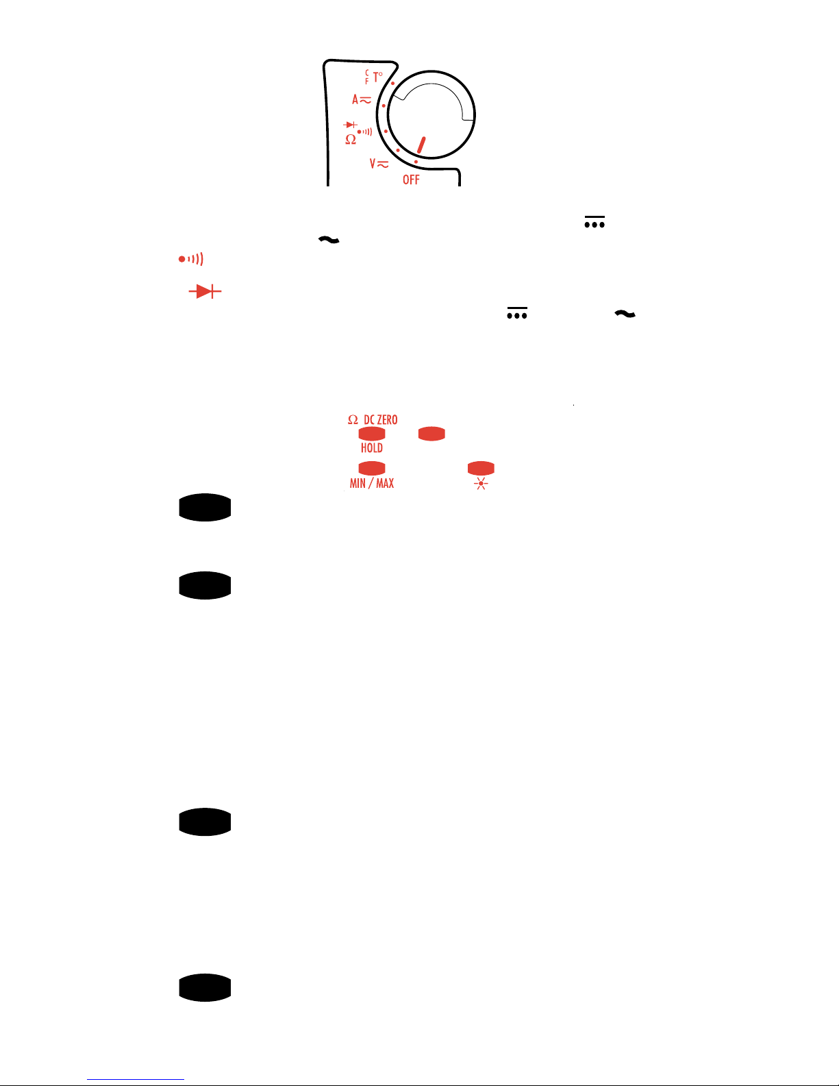
Commutateur des 5 fonctions
OFF = Position arrêt (économie de la pile)
V DC/AC = Voltmètre ou mesure de tension électrique en continu
ou alternatif jusqu'à 600 Volts sous haute impédance .
= Test sonore de continuité pour une résistance R £ 40 W, et
mesure de résistances jusqu'à 4 kW.
= Test semi-conducteurs.
A DC/AC = Mesure du courant électrique en continu ou alternatif
par pince jusqu'à 400 A.
T° = Mesure de la température interne ou externe avec une sonde
thermocouple. (Adaptateur et sonde voir page pièces détachées).
Ω Ω
Ω Ω
Ω
Page 6
6
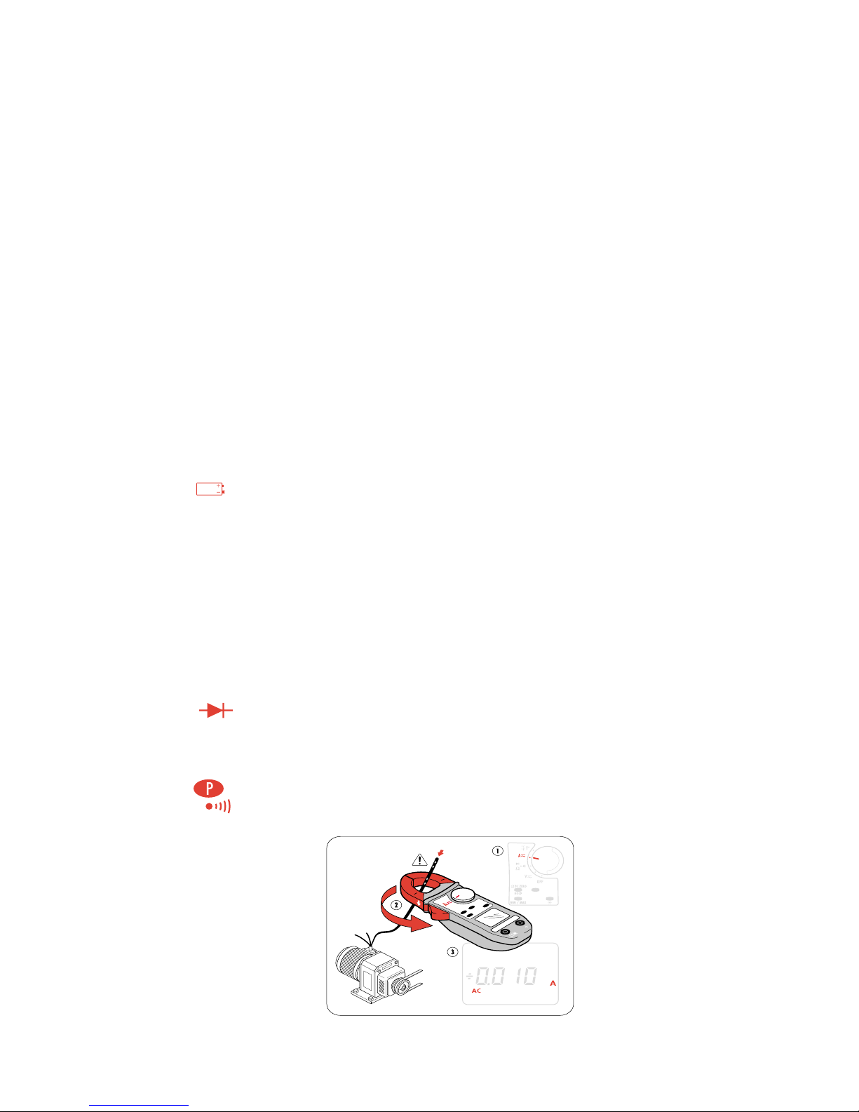
Lecture de l'afficheur.
Le symbole concerné s'allume lorsque la fonction est en activité.
Usure de la pile
PEAK
En fonction V et A en mode MIN/MAX lorsque l'on sollicite la valeur PEAK.
MAX Indique une valeur maximale en mode MIN/MAX.
MIN Indique une valeur minimale en mode MIN/MAX.
HOLD La dernière valeur est mémorisée.
AC La mesure en cours se fait en alternatif (clignote lorsque la pince a
sélectionné automatiquement le mode de mesure, et fixe si le mode
est sélectionné manuellement)
DC La mesure en cours se fait en continu (clignote lorsque la pince a
sélectionné automatiquement le mode de mesure, et fixe si le mode
est sélectionné manuellement)
+ ou - Indique la polarité en continu et en lecture de valeur PEAK (Crête)
Test de semi-conducteur
T° INT Position T° du commutateur ou si le thermocouple branché sur les
bornes est coupé, ou non branché (mesure de température interne)
T° EXT
Position T° du commutateur et lorsque le thermocouple est correctement branché
Le contrôleur est en fonctionnement permanent (suppression de l'arrêt automatique
)
Fixe: lorsque la fonction continuité est sélectionnée
Clignotant: lorsque la fonction V-Live est sélectionnée
Combinaison des touches.
Modification du seuil du "BIP" en fonction continuité: Appui maintenu
sur la touche jaune et amener le commutateur rotatif de la position OFF à Ω.
Le réglage est possible de 1Ω à 40Ω par appuis successifs sur la touche jaune.
Une fois la valeur choisie, actionner le commutateur pour la mémoriser.
Suppression de l'arrêt automatique: Appui maintenu sur la touche HOLD
et amener le commutateur de la position OFF à Ω .
Programmation de la fonction V-Live: Appui maintenu sur la touche
HOLD et amener le commutateur de la position OFF à V.
Date de dernière calibration: Appui maintenu sur la touche MIN/MAX et
amener le commutateur de la position OFF à V.
Visualisation de la version du logiciel interne: Appui maintenu sur la
touche HOLD et ammener le commutateur de la position
OFF
à A. La version du
logiciel est affichée pendant 2 secondes, puis on visualise tous les segments de
l'afficheur.
Mise en configuration par défaut: Appui maintenu sur la touche jaune et
amener le commutateur de la position OFF à A.
Configuration par défaut: seuil BIP: 40 Ω.
arrêt automatique
sans fonction V-Live
avec unité en température: °C
Branchement des fils sur le contrôleur.
Placer la fiche du fil noir dans la borne marquée "COM".
Placer la fiche du fil rouge dans la borne marquée "+".
Page 7
7
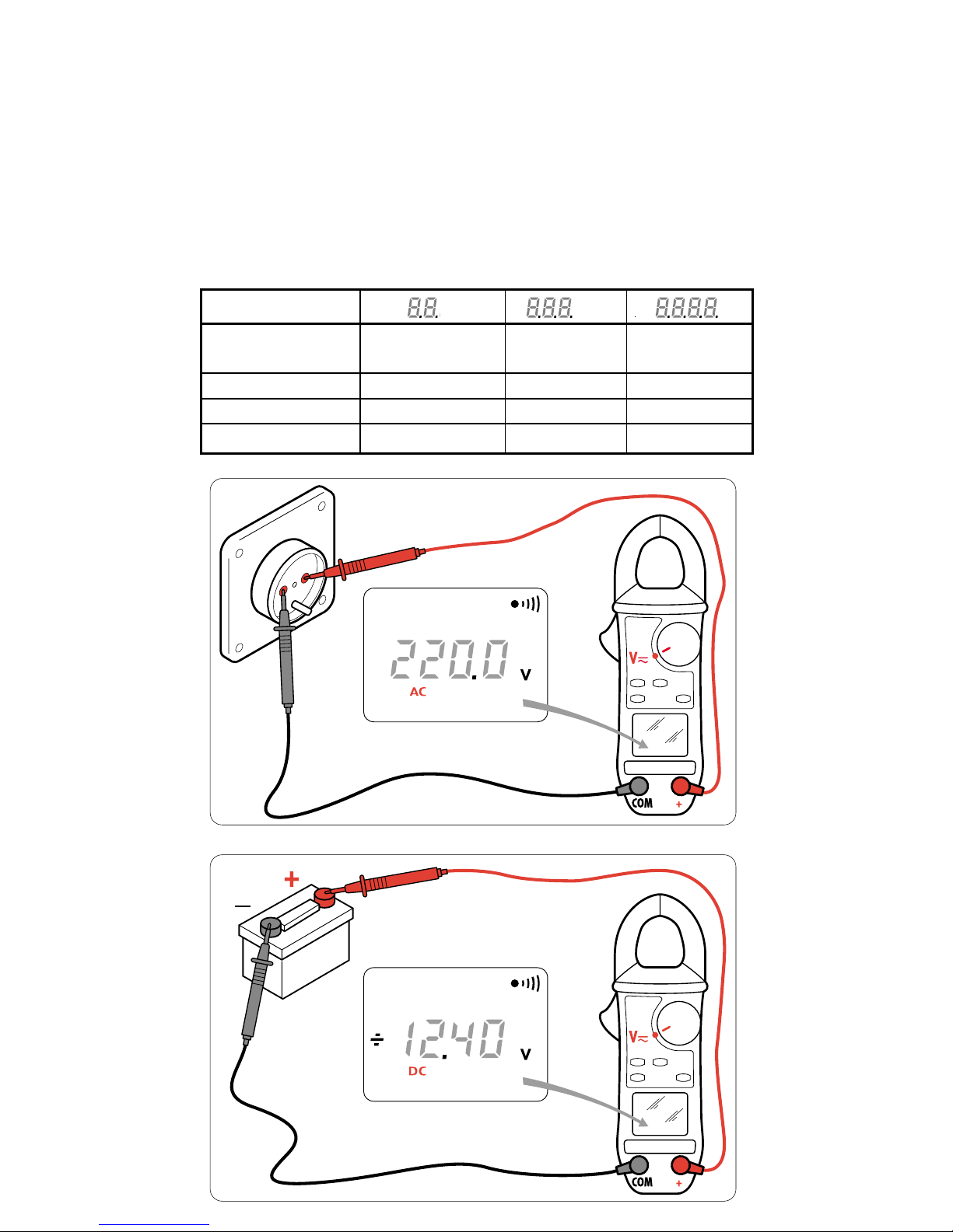
Gamme d'affichage V V V
Etendue de mesure 0,20 - 39,99 V 40,0 - 399,9 V 400 - 600 V DC
400 - 900 V crête
Précision 1% L ± 5 points 1% L ± 2 points 1% L ± 2 points
Résolution 10 mV 0,1 V 1 V
Impédance d'entrée 1 MΩ
Mesure des tensions continues ou alternatives.
Placer le commutateur sur la fonction voltmètre V .
Placer les pointes de touche en parallèle sur le circuit à mesurer
.
La commutation de gamme et la sélection AC/DC sont automatiques.
En V DC, l'affichage indique:
OL
___
au delà de + 600 V
OL
___
au delà de - 600 V
En V AC, l'affichage indique: OL
au delà de 900 V crête
En V AC, un bip sonore répétitif indique que la tension mesurée est supérieure
à la tension de sécurité normative vis à vis de l'utilisateur, soit 30V AC (45V DC
ou crête) si (fonction V-Live) progrmmée.
Page 8
8
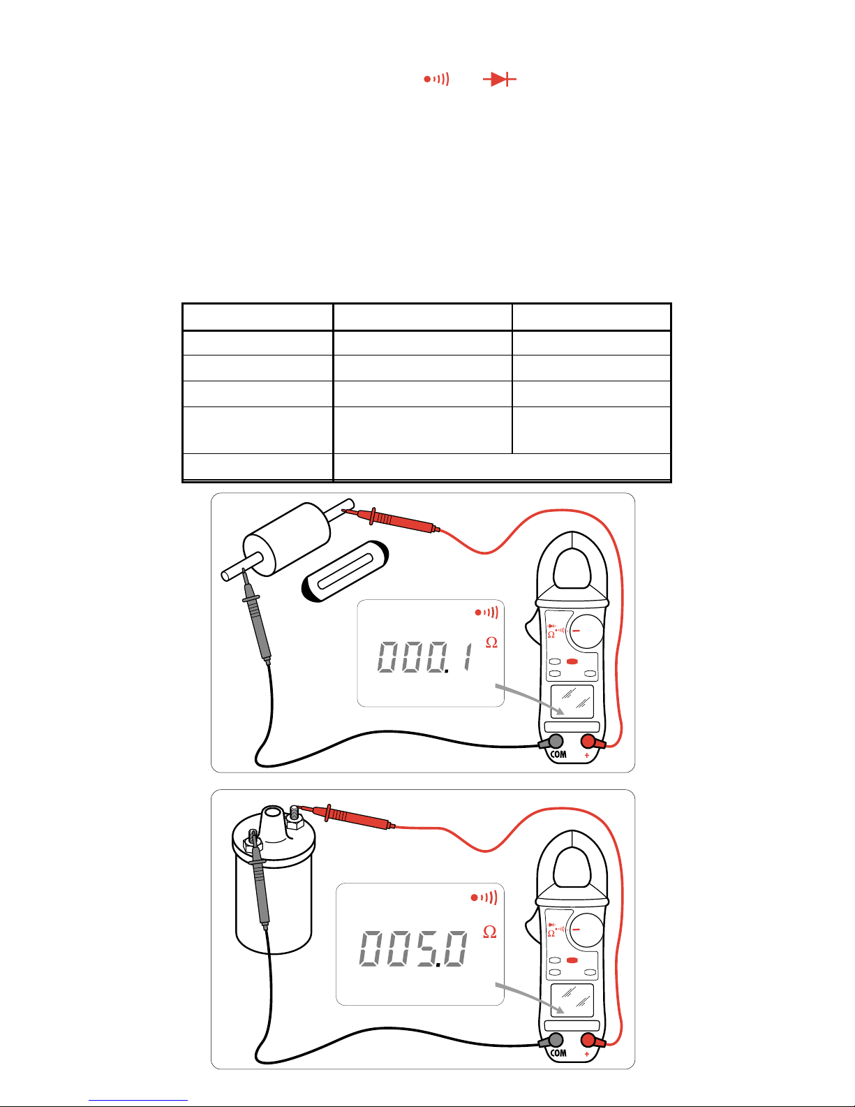
Mesure de continuité et de résistance.
CONTINUITE
Placer le commutateur sur la position
Ω
Contrôler le circuit à mesurer avec les pointes de touche. Le bip sonore de
continuité sera actif pour une résistance ≤ seuil choisi par programmation ( 40
Ω
par défaut).
RESISTANCE
A partir de la position Continuité, appuyer sur la touche jaune (fonctions
secondaires) afin de sélectionner la fonction Résistance.
Contrôler le circuit à mesure avec les pointes de touche.
La commutation de gamme est automatique.
Le dépassement de calibre est signalé sur l'afficheur par OL
Possibilité de compenser la résistance des cordons par un appui prolongé sur la
touche HOLD et en court-cicuitant les cordons.
Gamme d'affichage 400 Ω 4000 Ω
Etendue de mesure 0,0 - 399,9 Ω 400 - 3999 Ω
Précision 1,5 L ± 2 points 1,5 L ± 2 points
Résolution 0,1 Ω 1 Ω
Tension 3,2 V 3,2 V
en circuit ouvert
Protection 500 V AC ou 750 V (DC ou crête)
Page 9
9
1
0
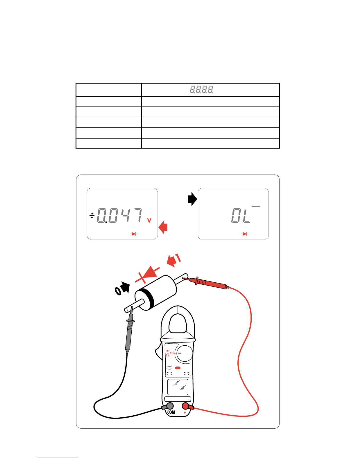
Mesure des diodes.
A partir de la position la position Résistance, appuyer sur la touche jaune
(fonctions secondaires) afin de sélectionner la fonction Test diode.
Contrôler le circuit à mesurer avec les pointes de touche.
Indication de jonction en court-circuit: bip sonore pour un seuil < 0,050 V
Indication de jonction en inverse: affichage OL
___
Gamme d'affichage V
Etendue de mesure 0 - 3,999 V
Courant de mesure 500 µA
Précision 1,5 L ± 2 points
Résolution 0,001 V
Protection 500 V AC ou 750 V (DC ou crête)
Page 10
10
Mesure de température
Sans sonde
La mesure de la température affichée est celle de l'appareil, équivalent à la
température ambiante après stabilisation thermique.
Les symboles T° INT apparaissent sur l'afficheur.
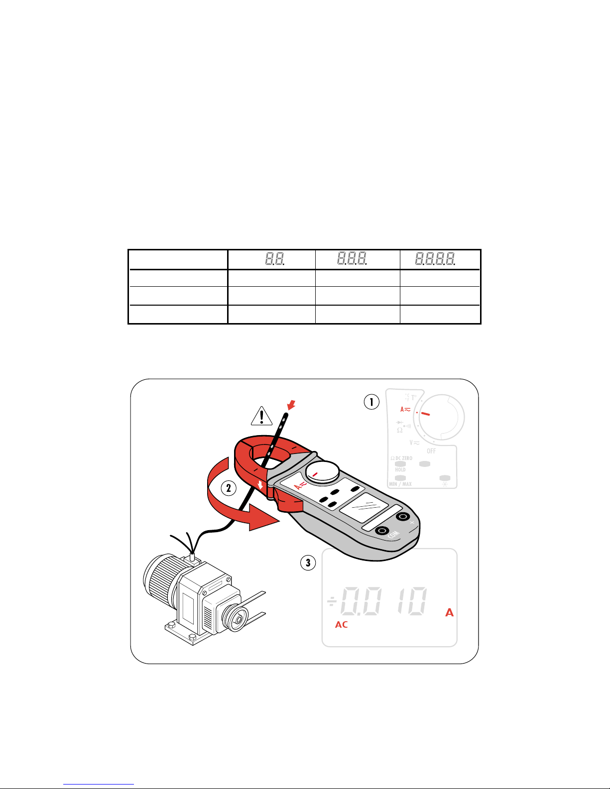
Mesure des intensités continues ou alternatives.
Placer le commutateur sur la fonction ampèremètre A.
Ouvrir la mâchoire de la pince avec la gâchette, et insérer le conducteur sur
lequel on veut faire la mesure.
Relâcher la gâchette en veillant au bon contact des mâchoires afin de refermer
correctement le circuit magnétique.
La commutation de gamme et la sélection AC/DC sont automatiques.
En DC, le courant résiduel au zéro peut être corrigé par un appui maintenu sur
la touche HOLD
En intensité DC, le courant max. est de 400 A
En A DC, l'affichage indique: OL
___
au delà de + 399,9 A
OL
___
au delà de – 399,9 A
En A AC, l'affichage indique OL au delà de 600 A crête
Gamme d'affichage A A A
Etendue de mesure 0,20 - 39,99 A 40,0 - 399,9 A 400 - 600 A crête
Précision 1,5% ± 10 points 1,5% ± 2 points 1,5% ± 2 points
Résolution 10 mA 0,1 A 1 A
Page 11
11
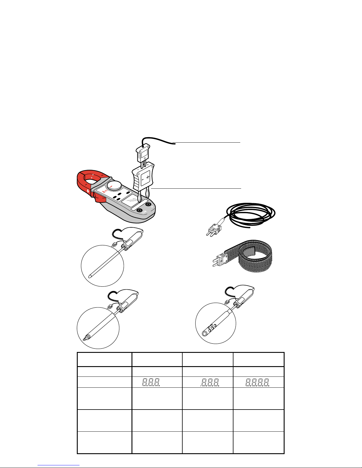
Mesure de température
Avec sondes (Adaptateur et sondes sont en option)
Brancher l'adaptateur thermocouple sur les deux bornes d'entrée de la pince en
respectant la polarité
( - sur borne COM et + sur borne + )
Connecter sur l'adaptateur la sonde souhaitée.
712-01 Adaptateur
DX.12-06 Sonde souple
DX.12-08 Sonde bracelet
DX.12R Rallonge (s'utilise avec la sonde bracelet)
DX.12-11 Sonde à aiguille standard
DX.12-15 Sonde contact surface
DX.12-17 Sonde à air
Les symboles T° EXT apparaissent sur l'afficheur.
DX.12-11
DX.12-15
DX.12-17
DX.12-06
DX.12-08
DX.12-11
DX.12R
DX.12-15
DX.12-17
712-01
DX.12-06
DX.12-08
Température interne Température externe Température externe
Type de sonde circuit intégré couple K couple K
Gamme d'affichage °C °C °C
Etendue de mesure -10°C à +50°C - 50,0°C à+399,9°C +400°C à+1000°C
+15°F à+120°F 50,0°F à+399,9°F +400°F à+1800°F
Précision ± 1,5 °C 1% L ± 1,5 °C 1% L ± 1,5 °C
± 2,7 °F 1% L ± 2,7 °F 1% L ± 2,7 °F
Résolution 0,1 °C 0,1 °C 1 °C
0,1 °F 0,1 °F 1 °F
Page 12
12
Pièces détachées
1
2
712
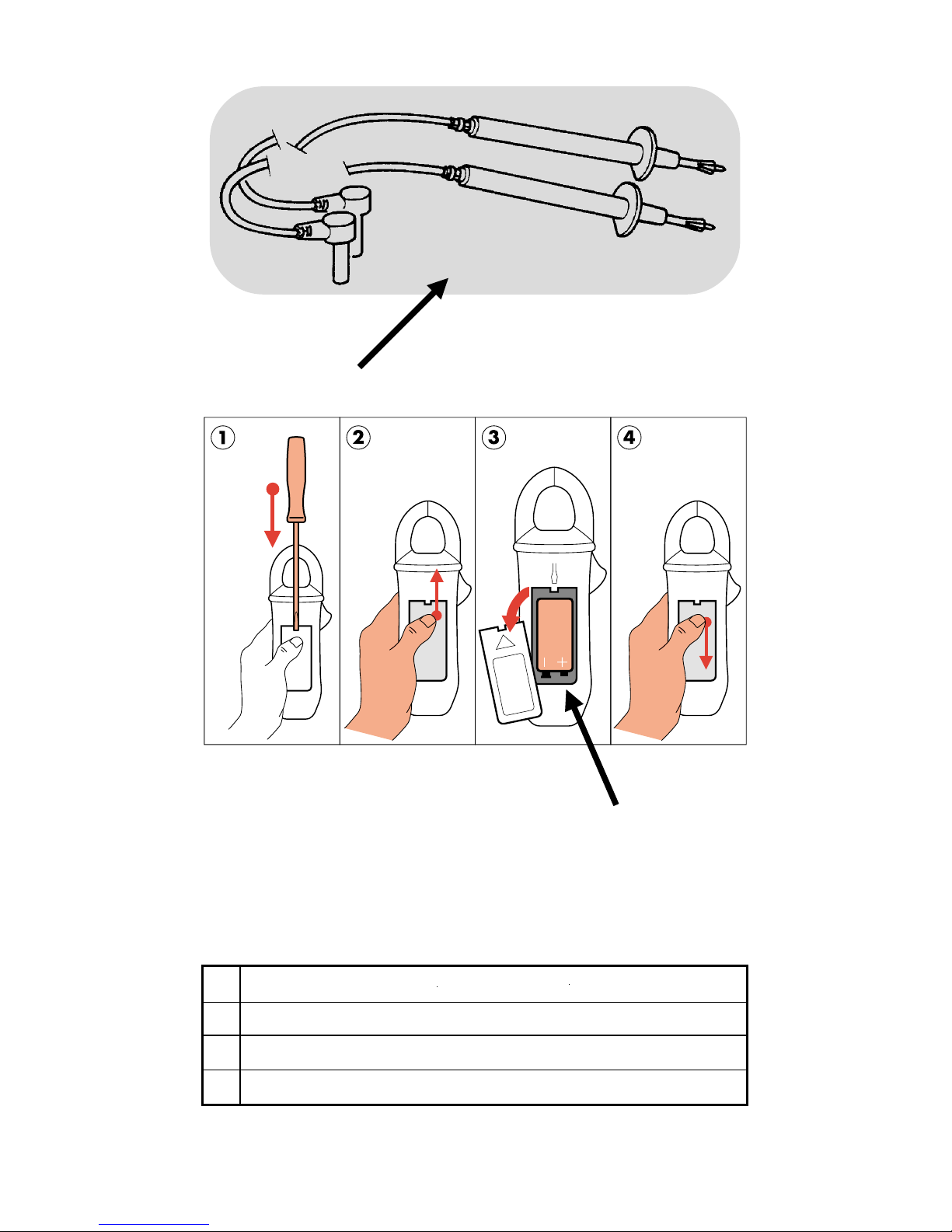
1 711.19 Jeu de 2 fils avec pointe de touche
2
pile 6LF22
Pile de 9 Volts
712.02 Trousse
En France, pour les renseignements techniques sur l'outillage à mains
téléphonez au 01 64 54 43 07 ou 45 14
Garantie : 1 an.
Attention : La ferritte, les accessoires (pointes de touche, trousse) sont des
consommables et n’entrent pas dans le cadre de la garantie.
Page 13

13
Safety
Never take measurements of resistances and diodes on a powered
circuit. Never use on voltage networks higher than 600 Vrms.
Before taking any measurement, make sure the power cables and the selector switch
are positioned correctly.
Never open the tester case before all the electrical sources have been disconnected.
Never connect to the circuit to be measured if the tester case is not closed correctly.
Use accessories complying with standards of safety (EN 61010-2-031), 600 V
minimum voltage and overvoltage category III.
Specifications
Overall dimensions :193 mm x 70 mm x 37 mm
Weight :260 grams
Opening of alligator clips :26 mm
1 battery :9 volts (type 6LF22)
Autonomy :100 hours or 6,000 measurements of
1 minute each. Automatically turns off
after 10 minutes without the selector
switch or a function button being activated.
NB :NB :
NB :NB :
NB :
Restarted by passing over the selector switch’s OFF position or by pressing any button.
Battery discharged indication: A flashing battery symbol indicates an
autonomy of less than 1 hour.
A fixed battery symbol implicates the battery
has to be changed.
Operating temperature : 0° C to + 50° C
Storage temperature : - 20° C to + 70° C
Relative humidity in operation : < 80 % RH
Relative humidity in storage : < 90 % RH
(up to + 45° C)
Conformity to standards : EN 61010.1 (Ed. 95) Class II (double insulation)
Degree of pollution 2
Installation category III
Service voltage 600 V
: EN 6110.2.032 (Ed. 93)
: EN 61326 (Ed. 98)
Degree of protection :
IP 40
according to EN 60529(Ed.92)
K 04
according to EN 50102 (Ed. 95)
Self extinguishing :
UL 94 V0
Radiated fields :
3 V/m
(according to IEC1000.4.3)
Free fall : 1 m
(according to IEC 68.2.32)
Vibrations :
.75 mm
(according to IEC 68.2.6)
Shocks :
.5 Joule
(according to IEC 68.2.27)
Electrical shocks :
6 kV
(according to IEC 1000.4.5)
Electrostatic discharge :
4 kV class 2
(according to IEC 1000.4.2)
Rapid transients :
2 kV
(according to IEC 1000.4.4)
Automatic or manual measurement mode selection (AC or DC) (manual mode selected
by pressing the yellow button)
Automatic measurement range selection
Automatic tester turn-off system
Recording functions of the MIN - MAX - PEAK values
Display Hold by pressing the HOLD button (blue button)
Liquid crystal display, 4,000 measuring points (limited to 600 V), 8 mm digit height
Display refresh rate : 400 ms
Backlighting controlled by a manual button (green button)
Automatic display of polarity (+ and -) for DC measurements and PEAK values
Display overLoad indication : OL
DC zeroing to correct for variations
Automatic compensation for resistance of measuring cables in ohmmeter function (W zero)
Measuring of currents by clamping
V-Live function. «BEEP» if voltage > 30 V
EN
Page 14
14
Switches for Additional Functions
YELLOW
In the V or A position, allows going from AC to DC
In the Ω position, allows going from continuity to resistance
tosemiconductor test
In the T° position, allows going from °C to °F
BLUE
HOLD/Ω/DCZero - Four different functions :
1- A short press on this button freezes the display. A second
press releases the display.
2- A short press on the HOLD button and then on the MIN/MAX
button preselects the MIN/MAX mode. The tester is connected.
A second press on HOLD makes the MIN/MAX mode effective.
3- A long press on this button allows automatically
compensating for the resistance of the power cables. To make
this compensation, short out the power cables connected to
the tester, continuity or resistance function selected.
4- A long press on this button allows automatically zero
compensating in the DC ammeter function.
BLACK
MIN/MAX This button circularly shifts the functions when actuated by
making short presses.
1st press : entry into the MIN/MAX mode ; the PEAK value
displays (only in volts or amperes ; otherwise, the MAX value displays)
2nd press : the MAX value displays
3rd press : the MIN value displays
4th press : return to the PEAK value (if effective ; otherwise, the
MAX value displays) Long press : exit from the MIN/MAX mode
(valid at any moment).
GREEN
A short press on this button backlights the display ; the
display automatically turns off after 2 minutes.
A long press displays the battery’s estimated remaining
autonomy expressed in hours.
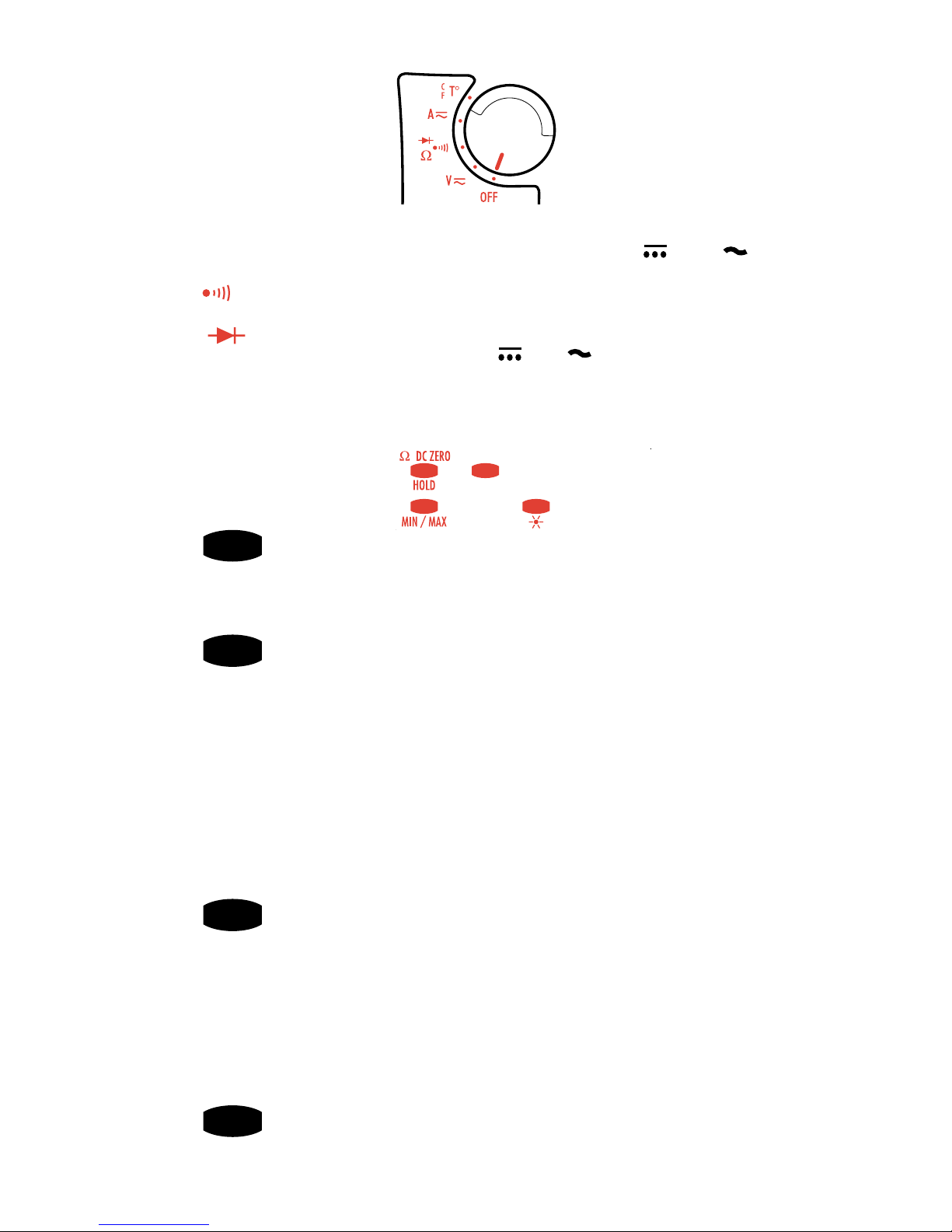
5 Position Selector Switch
OFF = position
(to save battery energy)
V
DC/AC
= Voltmeter or electrical voltage measurement in DC
or AC
up to 600 Volts under a high impedance
Ω = Audible test of continuity for a resistance R < 40 W and a measuring
of resistances up to 4 kW
= Semiconductor test
A DC/AC
= Electrical current measurement in DC or AC by clamping up to 400 A
T° = Measurement of the internal or external temperature with a thermo-
couple probe (adapter and probe, see page on spare parts).
Page 15
15
Button Combinations
Modifying the «BEEP» threshold in continuity function : Press and hold the
yellow button and set the selector switch from the
OFF position to Ω
..
..
.
The Ω value may then be set from 1 Ω to 40 Ω by successively pressing the yellow
button.
Once the value has been selected, actuate the selector switch to store it.
Disabling automatic turn-off :
Press and hold the
HOLD button and set the
selector switch from the
OFF position to Ω
..
..
.
Disabling the V-Live function : Press and hold the
HOLD button and set the
selector switch from the
OFF position to
V
..
..
.
Displaying the last calibration date : Press and hold the MIN/MAX button
and set the selector switch from the
OFF position to
V
..
..
.
Displaying the internal software version : Press and hold the
HOLD button
and set the selector switch from the OFF position to
A.
The software version
displays for 2 seconds and then all the display’s segments turn on.
Setting the default configuration : Press and hold the yellow button and
set the selector switch from the OFF position to
A.
Default configuration : BEEP threshold : 40 Ω
Automatic turn-off
With V-Live function
With temperature unit : °C
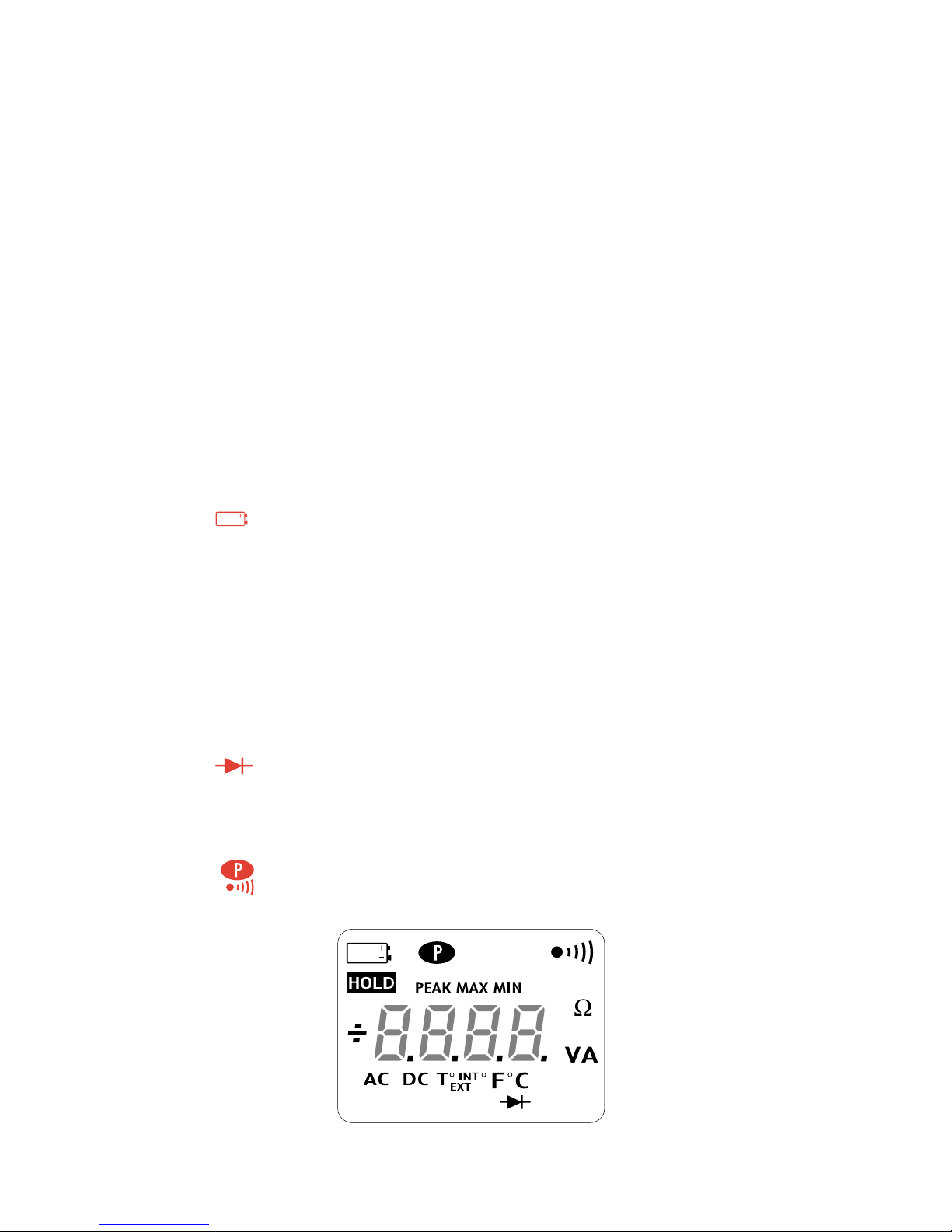
Reading the Display
The concerned symbol turns on when the function is active :
Battery discharged
PEAK In V and A function in MIN/MAX mode when the PEAK value is desired
MAX Indicates a maximum value in MIN/MAX mode
MIN Indicates a minimum value in MIN/MAX mode
HOLD The last value is stored
AC The current measurement is made in AC (flashes when the clamp has
automatically selected the measurement mode, and is fixed if the
mode is manually selected)
DC The current measurement is made in DC (flashes when clamping has
automatically selected the measurement mode, and is fixed if the
mode is manually selected)
+ or - Indicates the polarity in DC and readout of the PEAK value
Semiconductor test
T° INT T° position of the selector switch, or if the thermocouple probe
connected to the terminals is cut off or not connected (internal temperature measurement)
T° EXT T° position of the selector switch, and when the thermocouple probe
is correctly connected
The tester is in permanent operation (disabling automatic turn-off)
Fixed : when the continuity function is selected.
Flashing : when the V-Live function is selected.
Connections to the Tester
Place the black wire connecting tip in the terminal marked «COM».
Place the red wire connecting tip in the terminal marked «+».
Page 16
16
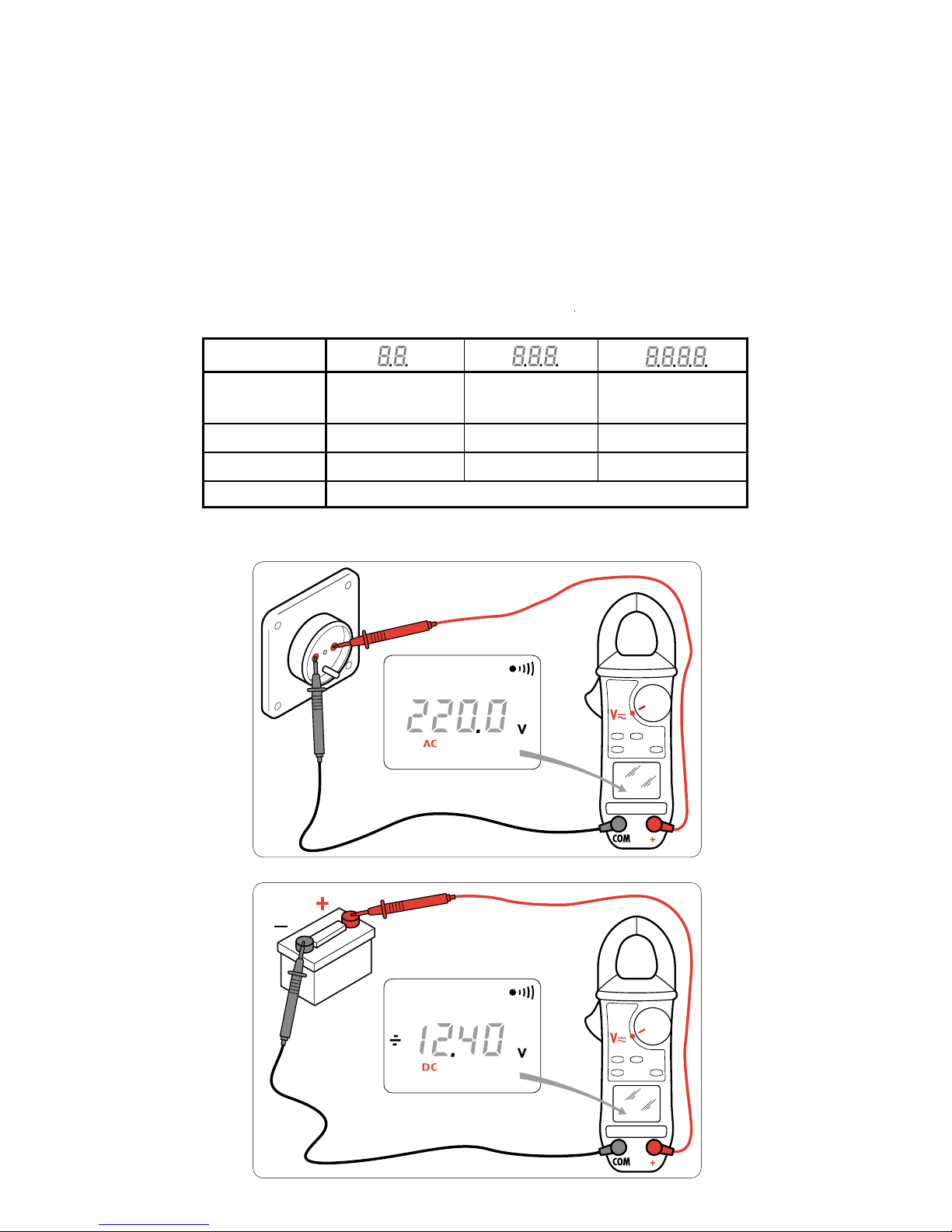
Measuring AC or DC Voltages (Voltmeter)
Set the selector switch to the voltmeter function V.
Place the contact tips in parallel on the circuit to be measured.
Range switching and AC/DC selection are automatic.
In V DC, the display indicates : OL
___
above + 600 V
OL
___
below - 600 V
In V AC, the display indicates : OL above 900 V peak
In V AC, an audible repetitive beeping indicates that the measurement voltage
is greater than the normative safety voltage to assure user protection, that is, 30
V AC (45 V DC or peak) (V-Live function).
Display Range V V V
Measurement 0,20 - 39,99 V 40,0 - 399,9 V 400 - 600 V DC
Range 400 - 900 V AC
Precision 1% ± 5 points 1% ± 2 points 1% ± 2 points
Resolution 10 mV 0,1 V 1 V
Input Impedance MΩ
Page 17
17
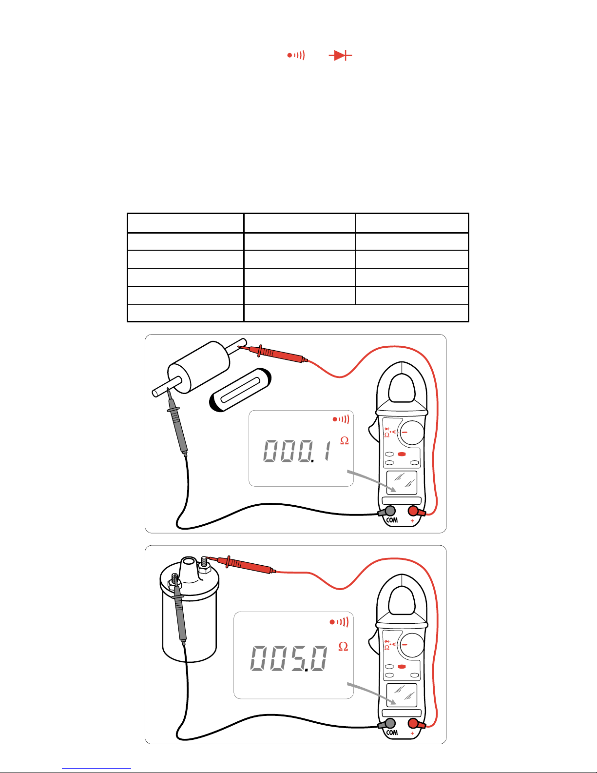
Measuring Continuity and Resistance (Ohmmeter)
CONTINUITY
Set the selector switch to the position
Ω
Check the circuit to be measured with the contact tips. Audible continuity beeping will
be active for a resistance
≤
threshold selected by programming (40 Ω by default).
RESISTANCE
Starting from the Continuity position, press the yellow button (secondary functions)
to select the Resistance function.
Check the circuit to be measured with the contact tips.
Range switching is automatic.
Calibrated range overloading is indicated on the display by OL.
Possibility of compensating for the resistance of the power cables by a long press
on the HOLD button and a shorting of the cables.
Display Range 400 Ω 4,000 Ω
Measurement Range 0,0 - 399,9 Ω 400 - 3,999 Ω
Precision 1,5 % ± 2 points 1.5 % ± 2 points
Resolution 0,1 Ω 1 Ω
Voltage in Open Circuit 3,2 V 3,2 V
Protection 500 V AC or 750 V (DC or Peak)
Page 18
18
1
0
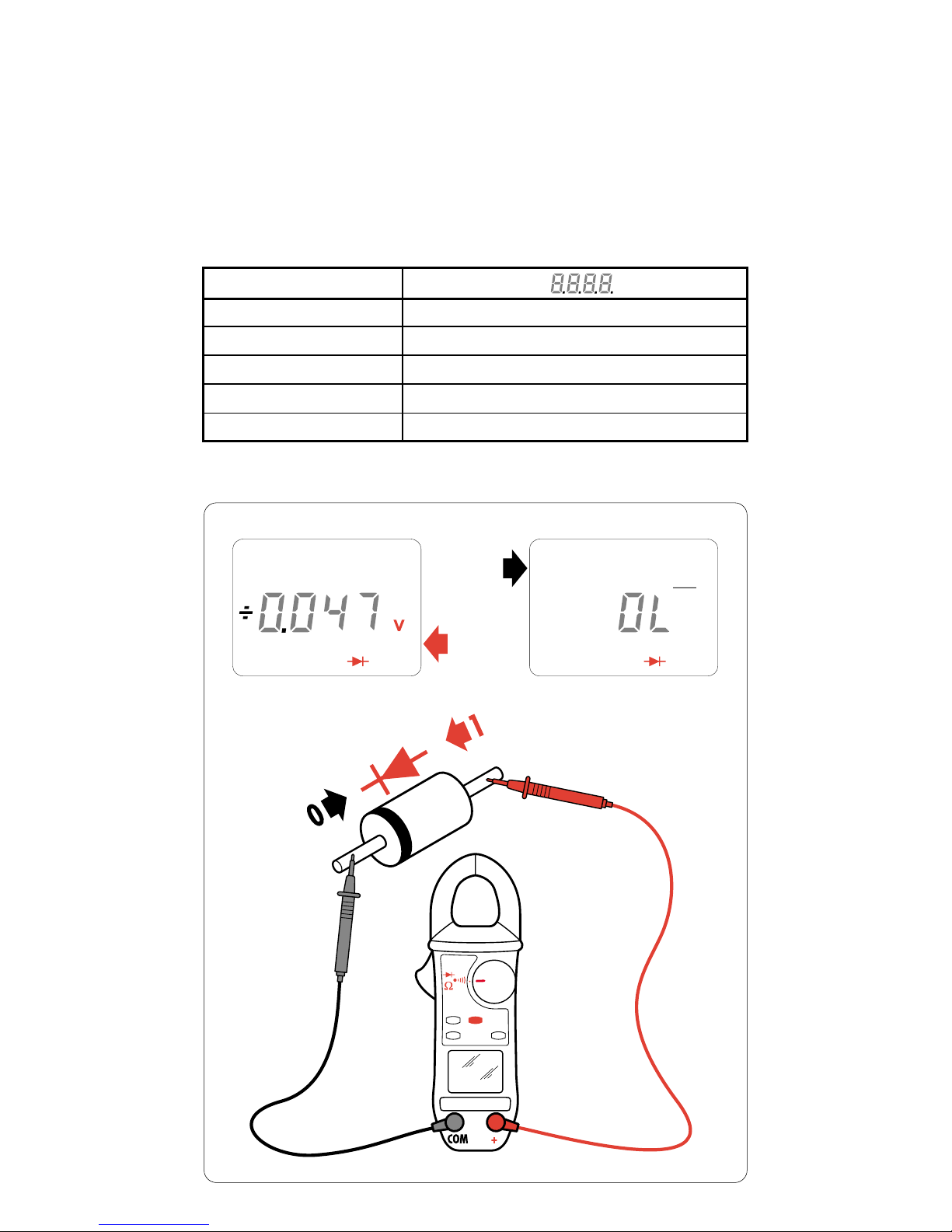
Measuring Diodes (Diode Tester)
Starting from the Resistance position, press the yellow button (secondary
functions) to select the Test Diode function.
Check the circuit to be measured with the contact tips.
Shorted junction indication : beeping for a threshold < 0,050 V
Reversed junction indication : OL
___
displays.
Display Range V
Measurement Range 0 - 3,999 V
Measurement Current 500 µA
Precision 1,5 % ± 2 points
Resolution 0,001 V
Protection 500 V AC or 750 V (DC or Peak)
Page 19
19
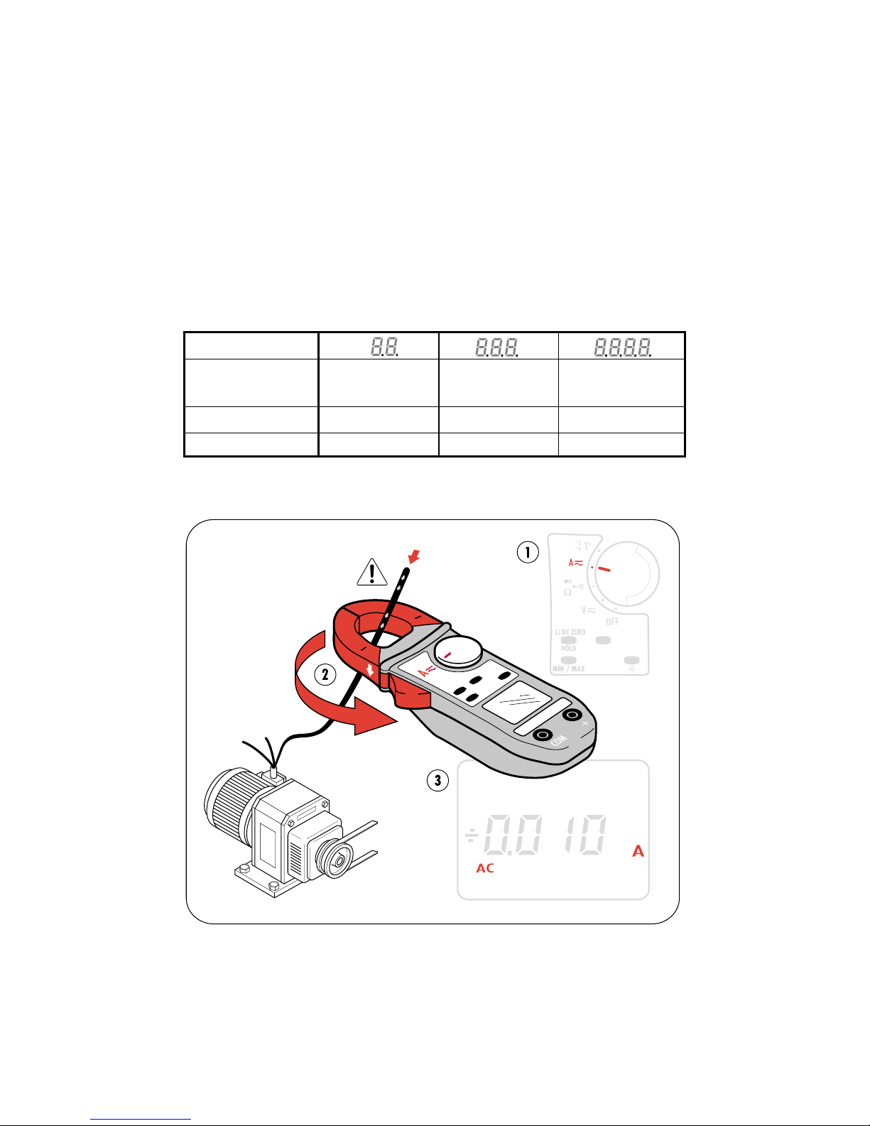
Measuring AC or DC Currents (Ammeter)
Set the selector switch to the ammeter function A.
Open the jaws of the alligator clip with the spring catch and insert it on the
conductor where the measurement is to be made.
Release the spring catch and make sure the jaws are in good contact to reclose the
magnetic circuit correctly.
Range switching and AC/DC selection are automatic.
In DC, the residual or zero current may be corrected by pressing and holding the
HOLD button.
In DC current, the maximum current is 400 A.
In A DC, the display indicates : OL
___
above + 399,9 A
OL
___
below - 399,9 A
In A AC, the display indicates : OL above 600 A peak.
Display Range A A A
Measurement 0,20 - 39,99 A 40,0 - 399,9 A 400 - 600 A peak
Range
Precision 1,5% ± 10 points 1,5% ± 2 points 1,5% ± 2 points
Resolution 10 mA 0,1 A 1 A
Measuring Temperature
Without probe
The displayed temperature measurement is that of the tester,
equivalent to the ambient temperature after thermal stabilization.
The T° INT symbols appear on the display.
Page 20
20
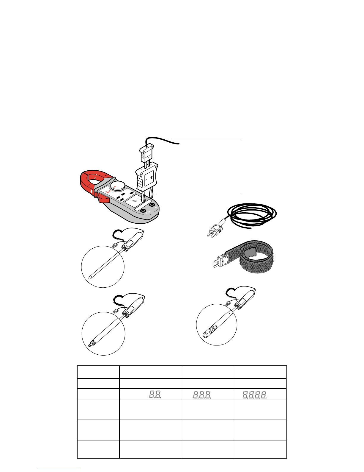
Measuring Temperature
With probes (adapter and probes are optional)
Connect the thermocouple adapter to the two input terminals of the clamping ;
make sure polarity is respected.
(- on the COM terminal and + on the + terminal)
Connect the desired probe to the adapter.
712-01 Adapter
DX.12.06 Flexible probe
DX.12.08 Bracelet probe
DX.12R Extension (is used with the bracelet probe)
DX.12.11 Standard needle probe
DX.12.15 Surface contact probe
DX.12.17 Air probe
The T° EXT symbols appear on the display.
DX.12-11
DX.12-15
DX.12-17
DX.12-06
DX.12-08
DX.12-11
DX.12R
DX.12-15
DX.12-17
712-01
DX.12-06
DX.12-08
Internal Temperature External Temperature External Temperature
Probe Type Integrated Circuit K Couple K Couple
Display Range ° C ° C ° C
Measurement -10° C to + 50° C -50.0° C to + 399,9° C +400° C to + 1,000° C
Range
+15° F to +120° F -50° F to + 399,9° F +400° F to + 1,800° F
Precision ± 1,5° C 1% L ± 1,5° C 1% L ± 1,5° C
± 2,7° F 1% L ± 2,7° F 1% L ± 2,7° F
Resolution 0,1° C 0,1° C 1° C
0,1° F 0,1° F 1° F
Page 21
21
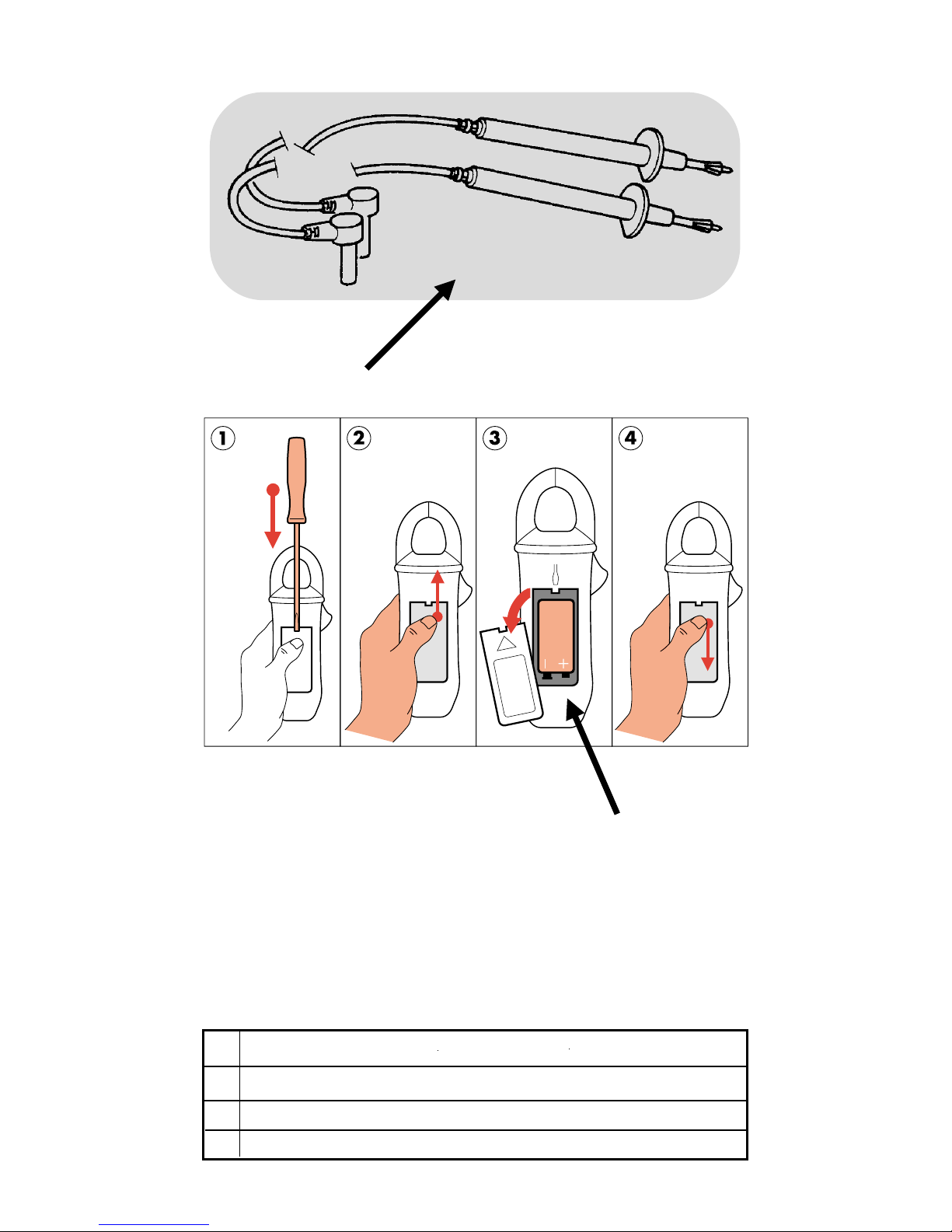
Spare Parts
1
2
712
1 711.19 2-wire set with contact tips
2 6LF22 battery 9 Volt battery
712.02 Wallet
Warranty : 1 year.
N.B.: the ferrite and accessories (key tip, case) are consumables and are not
covered by the warranty.
Page 22

22
Sicherheit
Auf keinen Fall Widerstands- oder Diodenmessungen an einer
Schaltung durchführen, an der Spannung anliegt.
Auf keinen Fall mit Spannungsnetzen mit mehr als 600 V eff. verwenden.
Vor den Messungen sicherstellen, dass die Kabel und der Drehschalter richtig stehen.
Auf keinen Fall das Gerätgehäuse öffnen, bevor es vom Stromnetz abgesteckt wurde.
Auf keinen Fall an die zu messende Schaltung anschließen, wenn das Gerätgehäuse
nicht korrekt verschlossen ist.
Das Zubehör in Übereinstimmung mit den Sicherheitsnormen (EN 61010-2-031)
verwenden mit einer Mindestspannung 600 V und Überspannungskategorie III.
Technische Daten
Platzbedarf : 193 x 70 x 37 mm
Gewicht : 260 Gramm
Öffnung der Backen : 26 mm
1 Batterie : 9 Volt
(Typ 6LF22)
Autonomie : 100 Stunden oder 6000 Messungen zu je 1 Minute.
Automatische Abschaltung nach 10 Minuten ohne
Betätigung des Drehschalters oder einer Funktionstaste
NB : Wiedereinschalten über die Position OFF des Schalters oder durch Betätigen einer beliebigen Taste.
Anzeigen der Batterielebensdauer
: Das Batteriesymbol blinkt, um eine restliche
Autonomie von < 1 Stunde anzuzeigen.
Sobald das Batteriesymbol nicht mehr blinkt, muss die Batterie ersetzt werden.
Betriebstemperatur : 0 bis 50 °C
Lagertemperatur : -20 bis +70 °C
Rel. Feuchtigkeit beim Gebrauch : < 80 % rel. Luftfeuchtigkeit
Rel. Feuchtigkeit bei der Lagerung : < 90 % rel. Luftfeuchtigkeit
(bis 45 °C)
Übereinstimmung mit den Normen :
EN 61010.1 (Ausg. 95)
Klasse II (doppelt isoliert)
Verschmutzungsgrad 2
Installationskategorie III
Betriebsspannung 600 V
: EN6110.2.032 (Ausg. 93)
: EN61326 (Ausg. 98)
Schutzart : IP 40
gemäß EN 60529 (Ausg. 92).
IK 04
gemäß EN 50102 (Ausg. 95)
Selbstlöschung : UL 94 V0
Abgestrahlte Felder : 3 V/m
(gemäß IEC 1000.4.3)
Freier Fall : 1 m
(gemäß IEC 68.2.32)
Schwingungen : 0,75 mm (gemäß IEC 68.2.6)
Stoß : 0,5 Joule
(gemäß IEC 68.2.27)
Elektroschock : 6 kV
(gemäß IEC 100.4.5)
Elektrostatische Entladung : 4 kV Klasse 2
(gemäß IEC 100.4.2)
Schnelle Übergärge : 2 kV
(gemäß IEC 100.4.4)
Auswahl des Messmodus (AC oder DC) automatisch oder manuell (gelbe Taste)
Auswahl der Betriebsbereiche: automatisch.
Automatische Abschaltung des Geräts.
Aufzeichnungsfunktionen der MIN – MAX-Werte und PEAK (Spitze)
Blockierung der Anzeige mit der HOLD-Taste (blau).
Flüssigkristallanzeige, 4000 Messpunkte (begrenzt auf 600 V), Höhe der Ziffern: 8 mm
Auffrischrate der Anzeige: 400 ms.
Hintergrundbeleuchtung mit manueller Tastensteuerung (grüne Taste).
Automatische Anzeige der Polung (+ und -) für Gleichstrommessungen (DC) und PEAK-Werte (Spitzen).
Anzeige des Übersteigens der Anzeigekapazität: auf dem Display steht OL.
Korrektur der Abweichungen bei der Gleichstrommessung (DC null).
Automatisches Ausgleichen des Widerstands der Messkabel in Ohmmeterbetrieb (Ω null).
Messung der Stromstärken mit Zange.
Funktion V-Live: „Piepton“, wenn Spannung > 30 V.
DE
Page 23
23
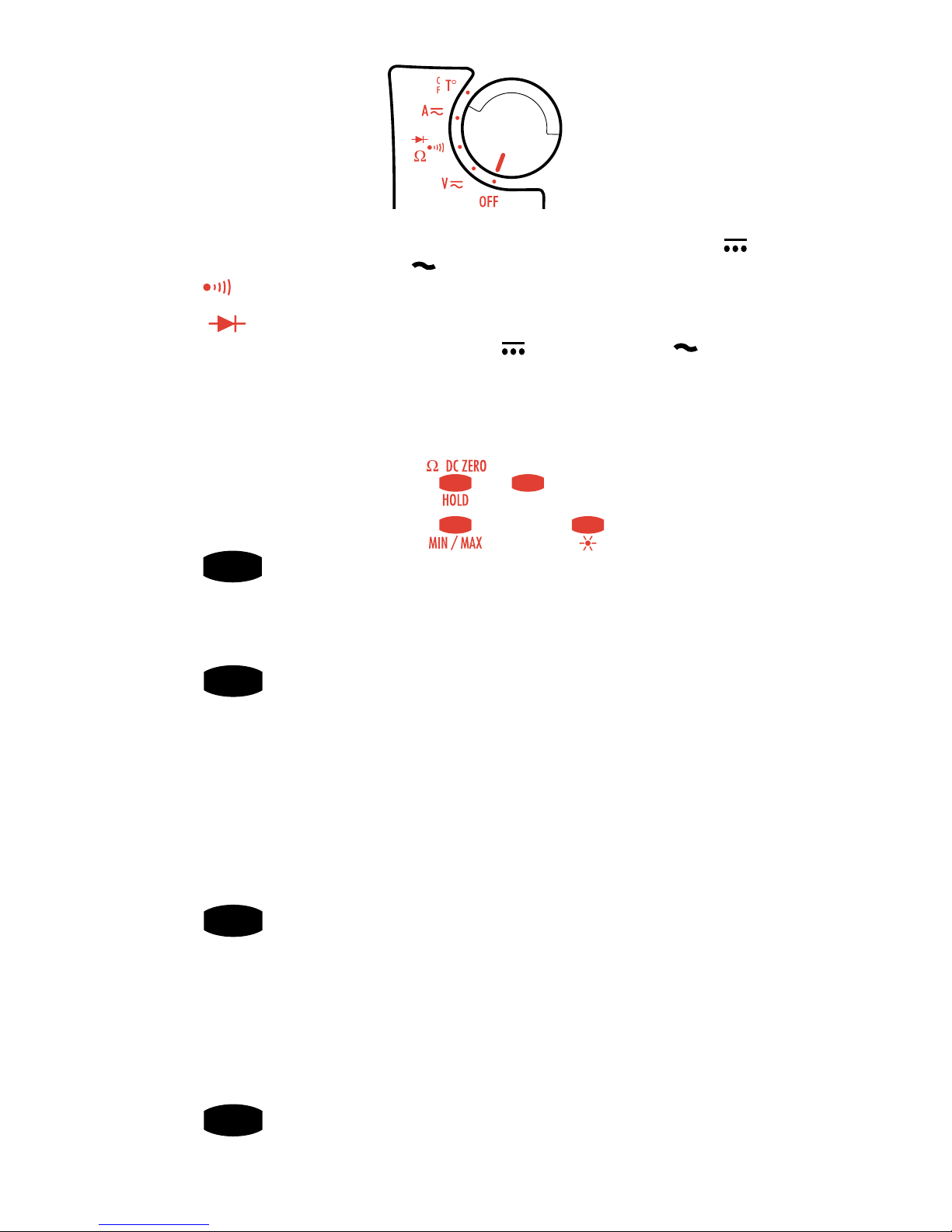
Ergänzende Funktionstasten
GELB
In Position V oder A des Drehschalters: zum Umschalten
zwischen Wechsel- und Gleichstrom
in Position Ω: Umschalter von Kontinuierlichkeit auf Widerstand
auf Halbleitertest
In Position T° Umschalten zwischen °C und °F.
BLAU
HOLD / Ω / DC Null – Vier verschiedene Funktionen:
1 - Ein kurzer Druck auf die Taste stoppt die Anzeige. Ein zweiter
Druck gibt sie wieder frei.
2 - Ein kurzer Druck auf die Taste HOLD und dann auf die Taste
MIN/MAX aktiviert den Modus MIN/MAX effektiv.
3 - Ein langer Druck auf die Taste erlaubt das automatische
Ausgleichen des Widerstands der Kabel. Dazu schließt man die
an das Gerät angeschlossenen Kabel bei ausgewählter
Funktion Kontinuitätsmessung oder Widerstandsmessung kurz.
4 - Ein langer Druck auf die Taster erlaubt das automatische
Nullabgleichen in der Betriebsweise Amperemeter DC.
SCHWARZ
MIN/MAX Die Taste funktioniert in kreisförmiger Weiterschaltung mit
kurzen Tastendrücken:
1. Druck: Aktivierung der Betriebsweise MIN/MAX. Anzeige
des Werts PEAK (Spitze) nur in Volt und Ampere, ansonsten
Anzeige des MAX-Werts)
3. Druck: Anzeige des MIN-Werts
4. Druck: Zurück zum PEAK-Wert (wenn effektiv, anderenfalls MAX-Wert)
Längerer Druck: Verlassen der Betriebsweise MIN/MAX
(jederzeit möglich)
GRÜN
Kurzer Druck: steuert die Hintergrundbeleuchtung des Displays.
Erlischt automatisch nach 2 Minuten.
Längerer Druck: Anzeige der geschätzten restlichen Autonomie
der Batterie, ausgedrückt in Stunden.
5 Funktionen-Drehschalter
OFF = Position Aus
(Stromsparen)
V
DC/AC
= Voltmeter oder Messung der elektrischen Spannung bei Gleichoder Wechselstrom bis 600 V unter hoher Impedanz.
Ω = Akustischer Test der elektrischen Kontinuität für einen Widerstand R ≤ 40
Ω und Messung von Widerständen bis zu 4 kΩ.
= Halbleitertest.
A DC/AC= Stromärkenmessung in Gleich- oder Wechselstrom mit
Zange bis 400 A.
T° = Innen-oder Aussentemperaturmessung mit einer Thermoelementsonde.
(Adapter und Sonde: siehe Ersatzteile).
Page 24
24
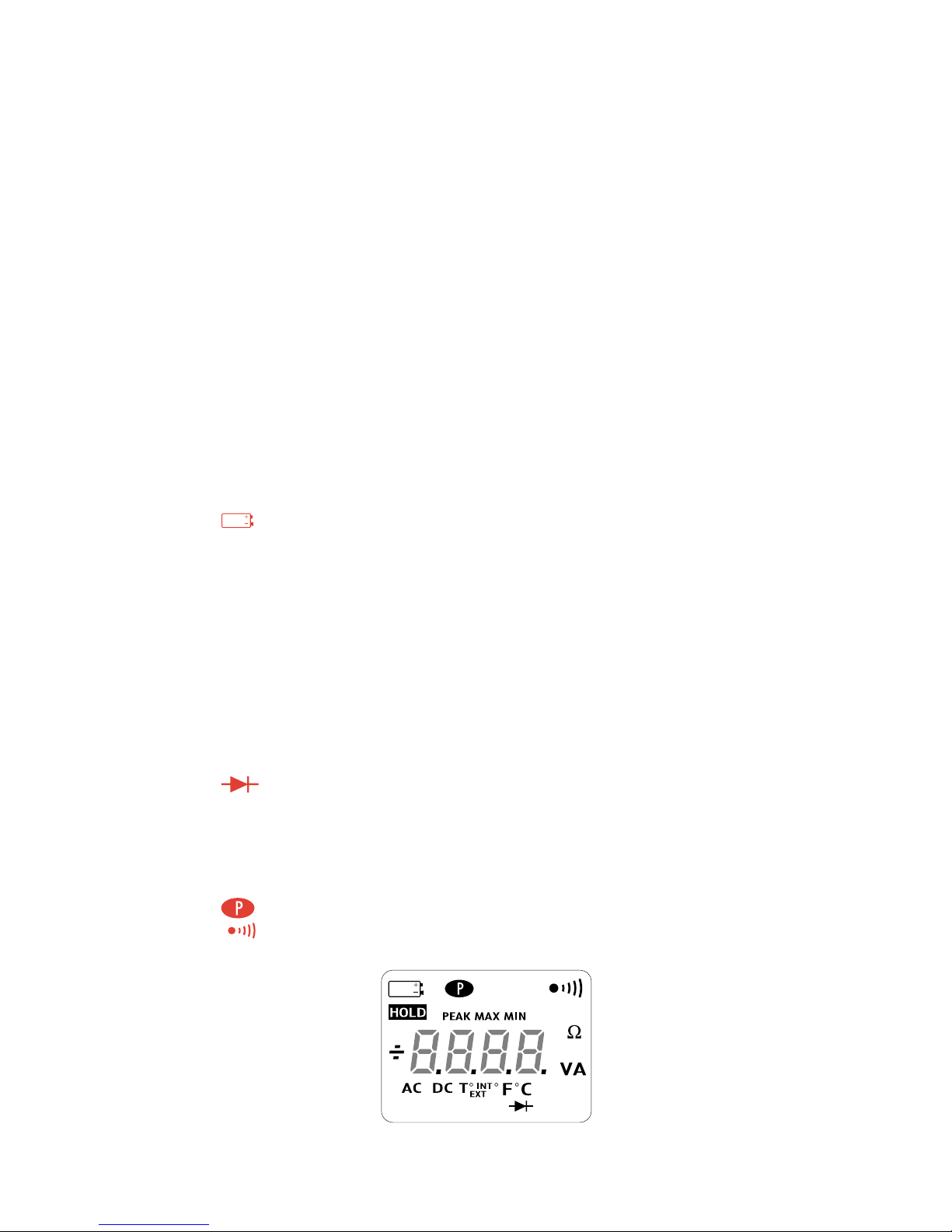
Ablesen der Anzeige:
Das betroffene Symbol schaltet sich beim Aktivieren seiner Funktion ein.
Ersetzen der Batterie
PEAK In den Funktionen V und A in der Betriebsweise MIN/MAX, wenn man
den PEAK-Wert verlangt
MAX Zeigt einen Höchstwert in der Betriebsweise MIN/MAX an.
MIN Zeigt einen Mindestwert in der Betriebsweise MIN/MAX an.
HOLD Der letzte Wert wird gespeichert.
AC Die laufende Messung erfolgt in Wechselstrom (blinkt, wenn die Zange
automatisch den Messmodus ausgewählt hat, leuchtet stationär wenn der
Modus manuell ausgewählt wird)
DC Die laufende Messung erfolgt in Gleichstrom (blinkt, wenn die Zange
automatisch den Messmodus ausgewählt hat, leuchtet stationär, wenn der
Modus manuell ausgewählt wird)
+ ou - Zeigt die Polung in Gleichstrom und in Lesung des PEAK-Werts (Spitze) an.
Halbleitertest
T° INT Position T° des Umschalters, oder wenn das an die Klemmen
angeschlossene Thermoelement ausgeschaltet oder nicht angeschlossen
ist (Messung der internen Temperatur)
T° EXT Position T° des Drehschalters und wenn das Thermoelement richtig
angeschlossen ist
Das Gerät ist in Dauerbetrieb (Deaktivierung des automatischen Ausschaltens)
Stationär: wenn die Funktion Kontinuität ausgewählt wurde
Blinkt: wenn die Funktion V-Live ausgewählt wurde
Kombinieren der Tasten
Ändern des Schwellenwerts des «Pieptons» je nach Kontinuität: Die gelbe Taste
niederhalten und den Drehschalter von OFF auf Ω drehen.
Die Einstellung ist von 1 Ω bis 40 Ω durch aufeinanderfolgendes Drücken der
gelben Taste möglich. Nach Auswahl des gewünschten Werts betätigt man den
Schalter, um den Wert zu speichern.
Deaktivieren des automatischen Ausschaltens: die Taste HOLD niederhalten und den
Drehschalter von OFF auf Ω drehen.
Deaktivieren der Funktion V-Live: die Taste HOLD niederhalten und den Drehschalter
von OFF auf V drehen.
Datum der letzten Kalibrierung: die Taste MIN/MAX niederhalten und den
Drehschalter von der Position OFF auf V drehen.
Anzeige der Version der internen Software: die Taste HOLD niederhalten und den
Drehschalter von der Position OFF auf A drehen. Die Softwareversion wird 2
Sekunden lang angezeigt, dann erscheinen alle Segmente des Displays.
Wiederherstellen der Standardkonfiguration: die gelbe Taste niederhalten und den
Drehschalter von der Position OFF auf A stellen.
Standardkonfiguration: Schwellenwert Piepton: 40 Ω
automatisches Ausschalten
mit Funktion V-Live
mit Temperatureinheit °C
Anschließen der Leiter an das Prüfgerät
Den Stecker des schwarzen Leiters in die Klemme mit der Kennzeichnung «COM» stecken.
Den Stecker des roten Leiters in die Klemme mit der Kennzeichnung “+“ stecken.
Page 25
25
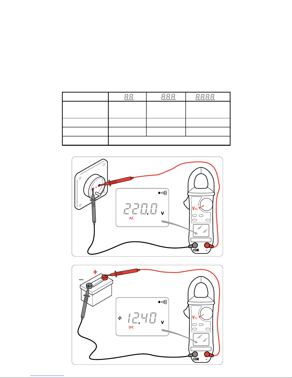
Messung von Gleich- und Wechselspannungen
Den Drehschalter auf die Funktion Voltmeter V stellen.
Die Messspitzen parallel auf die zu messende Schaltung platzieren.
Die Bereichsumschaltung und Auswahl von AC/DC erfolgen automatisch.
In V DC erscheint auf dem Display über + 600 V OL
___
über – 600 V OL
___
In V AC erscheint auf dem Display über 900 V Spitze OL
In VAC ertönt mehrmals ein Piepton, der darauf hinweist, dass die gemessene
Spannung größer ist als die normgemäß zulässige Sicherheitsspannung für den
Benutzer, das heisst 30 V AC (45 V DC oder Spitze) (Funktion V-Live)
Anzeigebereich V V V
Messbereich 0,20 – 39,99 V 40,0 – 399,9 V 400 – 600 V DC
400 – 990 V Spitze
Präzision 1 % L ± 5 Punkte 1 % L ± 2 Punkte 1 % L ± 2 Punkte
Auflösung 10 mV 0,1 V 1 V
Eingangsimpedanz 1 MW
Page 26
26
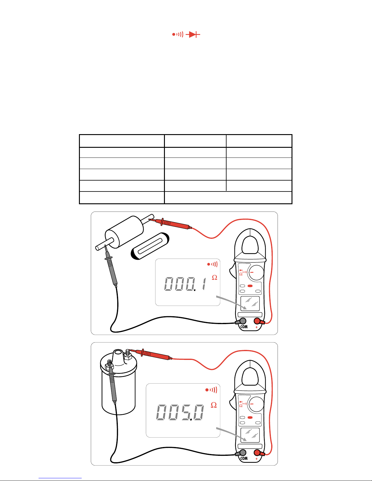
Messung von Kontinuität und Widerstand
KONTINUITÄT
Den Drehschalter auf die Position
Ω drehen.
Die zu messende Schaltung mit den Messspitzen prüfen. Der Piepton der
Kontinuität ist aktiv für einen Widerstand ≤ dem durch Programmierung
ausgewählten Schwellenwert (standardgemäß 40 Ω).
WIDERSTAND
Ausgehend von der Position Kontinuität drückt man auf die gelbe Taste
(Sekundärfunktionen), um die Funktion Widerstand auszuwählen.
Die zu messende Schaltung mit den Messspitzen prüfen.
Die Bereichsumschaltung erfolgt automatisch.
Die Kaliberübersteigung wird auf dem Display mit OL angezeigt.
Möglichkeit, den Widerstand der Kabel durch einen langen Druck auf die Taste
HOLD und durch Kurzschließen der Kabel auszugleichen.
Anzeigebereich 400 Ω 4000 Ω
Messbereich 0,0 – 399,9 Ω 400 – 3999 Ω
Präzision 1,5 L ± 2 Punkte 1,5 L ± 2 Punkte
Auflösung 0,1 Ω 1 Ω
Spannung in offener Schaltung 3,2 V 3,2 V
Schutz 500 V AC oder 750 V (DC oder Spitze)
Page 27
27
1
0
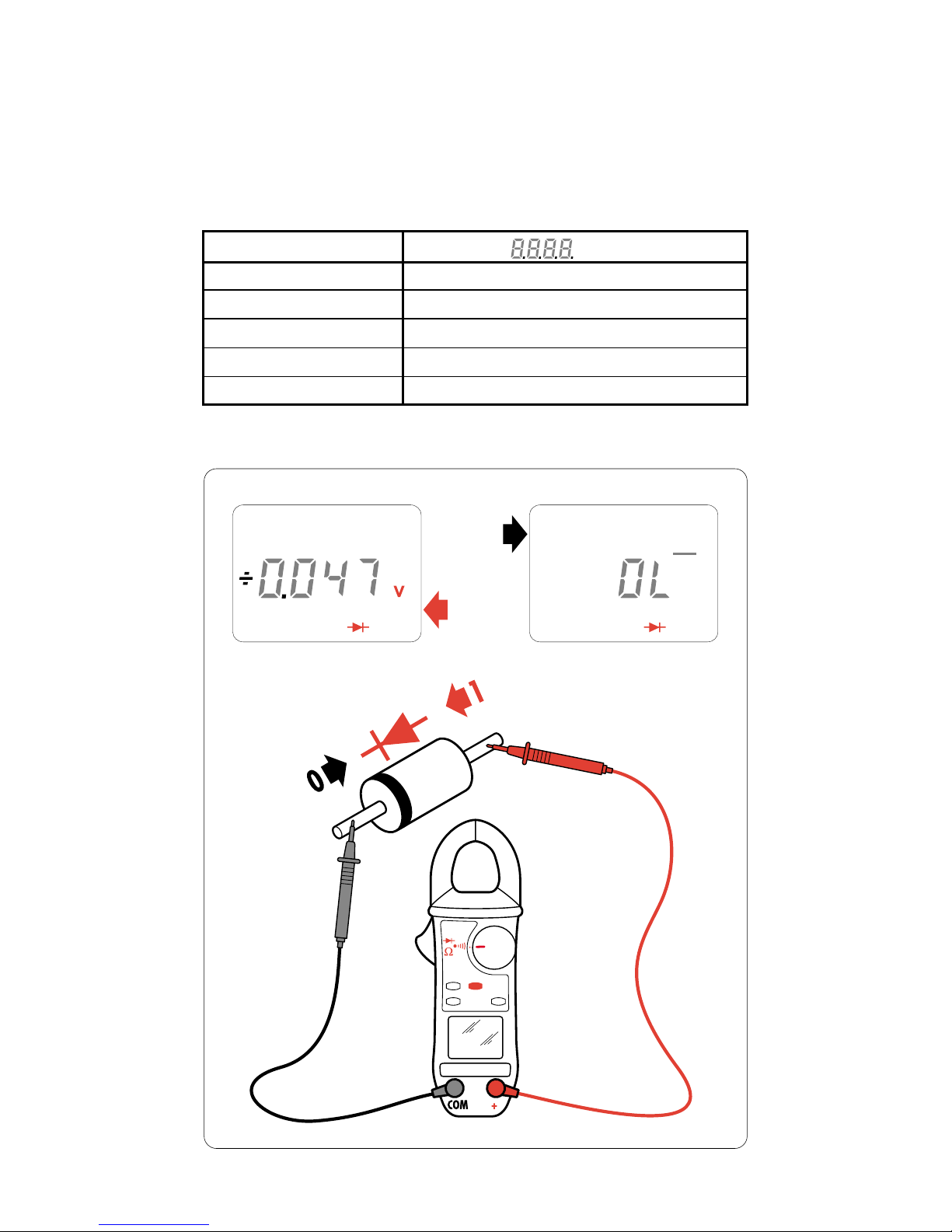
Messungen der Dioden
Ausgehend von der Position Widerstand drückt man auf die gelbe Taste
(Sekundärfunktionen), um die Funktion Diodentest auszuwählen.
Die zu messende Schaltung mit den Messspitzen prüfen.
Anzeige Verbindung in Kurzschluss: Piepton für eine Schwelle < 0,050 V
Anzeige Verbindung umgekehrt: Anzeige OL
___
Anzeigebereich V
Messbereich 0 – 3,999 V
Messstrom 50 µA
Präzision 1,5 L ± 2 Punkte
Auflösung 0,001 V
Schutz 500 V AC oder 750 V (DC oder Spitze)
Page 28
28
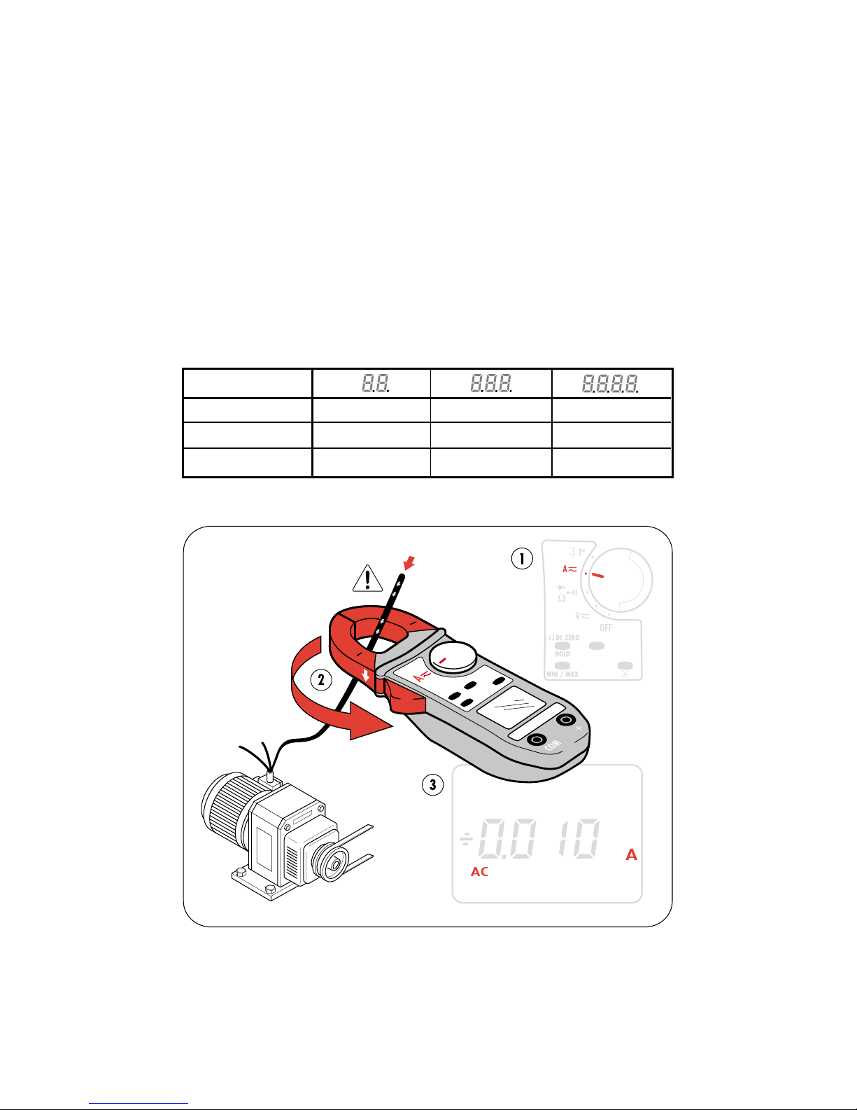
Messung von Gleichstrom- oder Wechselstromstärken
Den Drehschalter auf die Funktion Amperemeter A stellen.
Die Backen der Zange mit dem Drücker öffnen und den Leiter, an dem die Messung
erfolgen soll, einfügen.
Den Drücker wieder freigeben und dabei den guten Kontakt der Backen
sicherstellen, um den Magnetkreis wieder richtig zu schließen.
Die Bereichsumschaltung und die Auswahl AC/DC erfolgen automatisch.
In DC kann der Reststrom bis auf Null durch ein längeres Drücken der Taste HOLD
korrigiert werden.
In DC-Stärkenmessung beträgt der maximale Stromstärkenwert 400 A.
In A DC erscheint auf der Anzeige: OL
___
über + 399,9 A
OL
___
über – 399,9 A
In A AC erscheint auf der Anzeige OL, wenn 600 A Spitze überstiegen wird.
Anzeigebereich A A A
Messbereich 0,20 – 39,99 A 40,0 – 399,9 A 400 – 600 A Spitze
Präzision 1,5 % ± 10 Punkte 1,5 % ± 2 Punkte 1,5 % ± 2 Punkte
Auflösung 10 mA 0,1 A 1 A
Temperaturmessung
Ohne Sonde
Die angezeigte Temperatur ist die des Geräts und entspricht der Raumtemperatur
nach einer Stabilisierungszeit. Die Symbole T° INT erscheinen auf dem Display.
Page 29
29
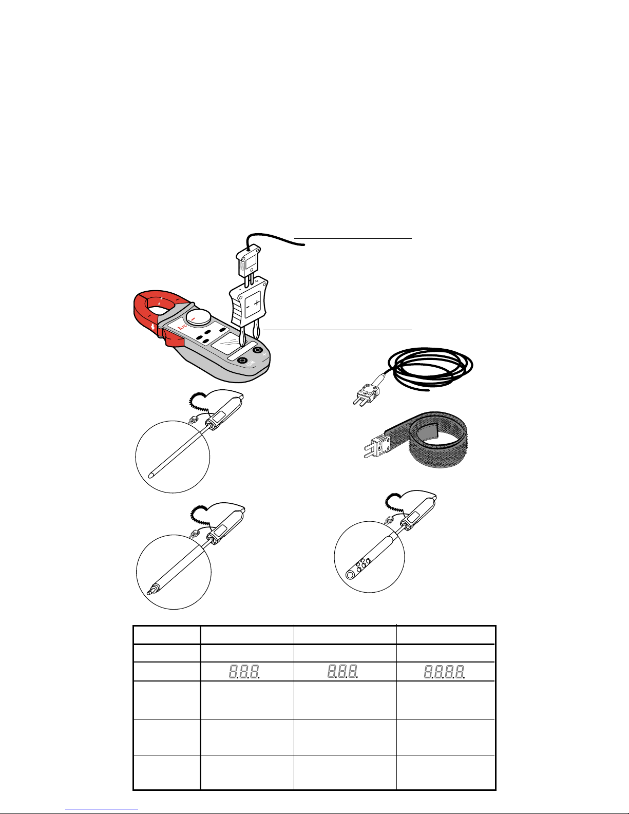
Temperaturmessung
Mit Sonden (Adapter und Sonden sind Zukaufmaterial)
Den Thermoelementadapter an die beiden Eingangsklemmen der Zange unter
Einhaltung der Polung anschließen (- an der Klemme COM und + an der Klemme +)
Die gewünschte Sonde an den Adapter anschließen.
712-01 Adapter
DX.12-06 Biegsame Sonde
DX.12-08 Armbandsonde
DX.12R Verlängerung (für die Armbandsonde)
DX.12-11 Standard-Nadelsonde
DX.12-15 Oberflächenkontaktsonde
DX.12-17 Luftsonde
Die Symbole T° EXT erscheinen auf dem Display.
DX.12-11
DX.12-15
DX.12-17
DX.12-06
DX.12-08
DX.12-11
DX.12R
DX.12-15
DX.12-17
712-01
DX.12-06
DX.12-08
Interne Temperatur Externe Temperatur Externe Temperatur
Sondentyp Integrierte Schaltung Element K Element K
Anzeigebereich °C °C °C
Messbereich -10 °C bis +50 °C -50,0 °C bis +399,9 °C +400 °C bis +1000 °C
+15 °F bis +120 °F 50,0 °F bis +399,9 °F +400 °F bis +1800 °F
Präzision ± 1,5 °C 1 % L ± 1,5 °C 1 % L ± 1,5 °C
± 2,7 °F 1 % L ± 2,7 °F 1 % L ± 2,7 °F
Auflösung 0,1 °C 0,1 °C 1 °C
0,1 °F 0,1 °F 1 °F
Page 30
30
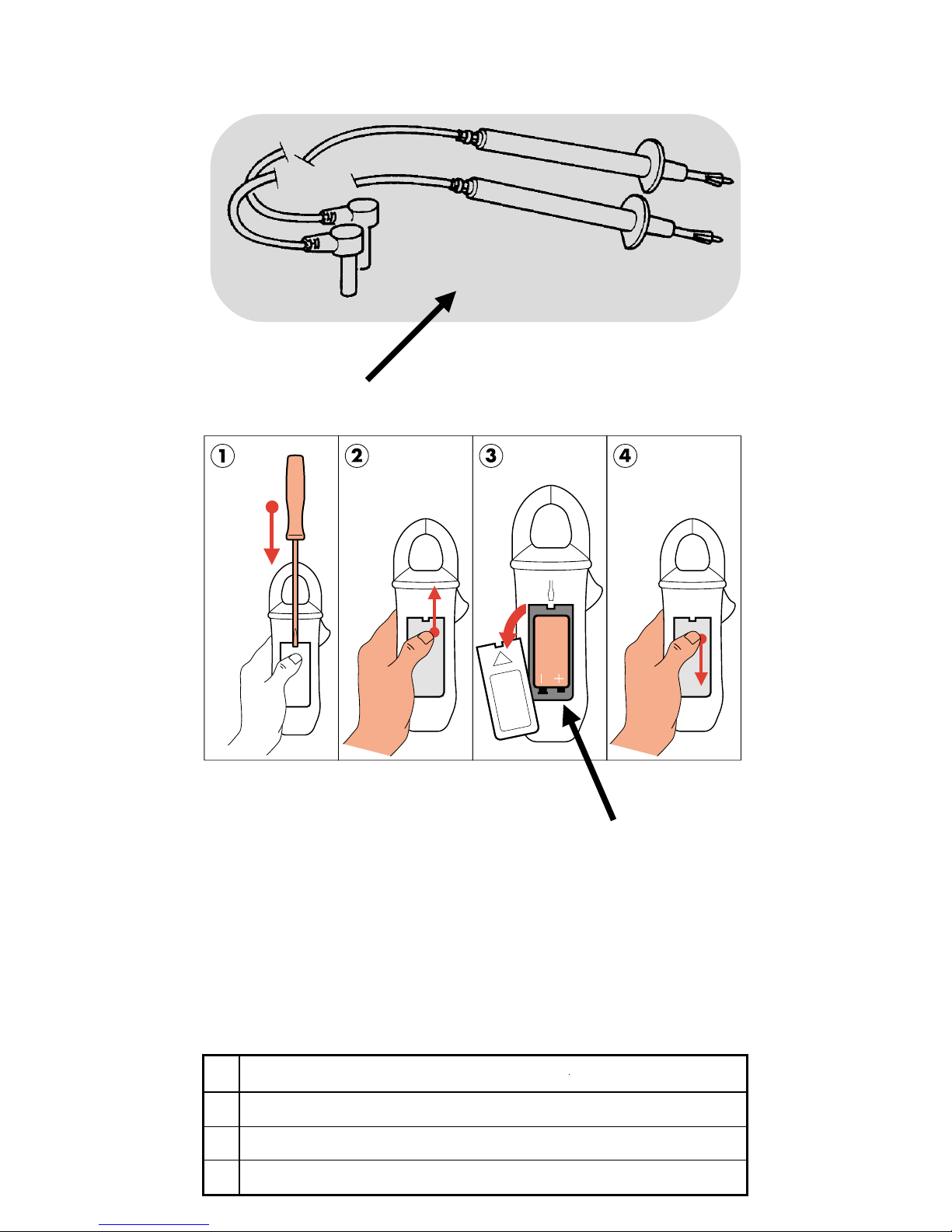
Ersatzteile
1
712
1 711.19 Satz 2 Leiter mit Messspitze
2
Batterie 6LF22
9 V-Batterie
712.02 Tasche
Garantie : 1 Jahr.
achtung : ferrit und Zubehör (Messpitzen, Tasche) sind Verbrauchsgüter, die
nicht in den Rahmen der Garantie fallen
2
Page 31

31
PL
Warunki bezpieczeństwa
Nie nalezy nigdy przeprowadzać pomiarów rezystancji ani testów diod w
obwodzie pod napięciem.
Nie nalezy uzywać miernika w sieciach o napięciu skutecznym wyzszym niz 600 V.
Przed kazdym pomiarem nalezy upewnić się, ze przewody i przełącznik znajdują się we właściwych pozycjach.
Nie nalezy otwierać obudowy aparatu przed odłączeniem go od zasilania.
Nie nalezy nigdy podłączać aparatu do kontrolowanego obwodu, jeśli obudowa nie jest prawidłowo zamknięta.
Nalezy stosować akcesoria zgodne z normami bezpieczeństwa (EN 61010-2-031),
dla minimalnego napięcia 600V i przeciązenia napięciowego kat. III.
Parametry techniczne
Wymiary : 193 x 70 x 37 mm
Waga : 260 g
Zakres szczęk : 26 mm
1 bateria : 9 V (6LF22)
Gotowo ść do pracy :100 godzin lub 6000 jednominutowych pomiarów.
Automatyczne wyłaczanie po 10 minutach, jeśli
nie wykonano zadnych manipulacji na
przełączniku lub przyciskach funkcyjnych.
NB:
Ponowne uruchomienie za pomocą przycisku OFF na przełączniku lub
dowolnego przycisku.
Wskaźnik zuzycia baterii : Migotający symbol baterii wskazuje gotowoś
do pracy < 1 godzina.
Symbol bez migotania wskazuje, ze nalezy zmienić baterię.
Temperatura uzytkowania : 0°do + 50°
Temperatura przechowywania : - 20°do + 70°
Wilgotność względna uzytkowania
: < 80 % HR
Wilgotność względna przechowywania
: < 90 % HR (do 45°C).
Zgodność z normami :
EN611010.1(Wyd.95) Klasa II (podwójna izolacja)
Stopień pyłoszczelności 2
Klasa instalacji III
Napięcie robocze 600V.
: EN6110.2.032 (Wyd.93)
: EN61326 (Wyd.98)
Stopień ochrony :
IP40 według EN 60527 (Wyd.92)
IK04 wed
ł
ug EN 50102 (Wyd.95)
Samowygaszanie : UL 94 VO
Pole promieniowania : 3 V/m (według CEI 1000.4.3)
Odporność na upadek : 1 m (według CEI 68.2.32)
Drgania : 0,75 mm (według CEI 68.2.6)
Udary : 0,5 J (według CEI 68.2.27)
Udary elektryczne : 6 kV (według CEI 1000.4.5)
Wyładowanie elektrostatyczne : 4 kV klasa 2 (według CEI 1000.4.2)
Przeciązenia : 2 kV (według CEI 1000.4.4)
Wybór trybu pomiarów (AC lub DC) automatyczny lub ręczny (przycisk koloru zółtego).
Automatyczny wybór funkcji.
Automatyczny system wyłączania aparatu.
Funkcje zapisu wartości do pamięci MIN – MAKS – PEAK (Wartość szczytowa)
Blokada wyświetłania za pomocą przycisku HOLD (przycisk niebieski).
Wyświetlacz ciekłokrystaliczny, maksymalne wskazanie 4000 (ograniczenie do 600 V), wysokość cyfr 8 mm.
Częstotliwość odświezania wyświetlania : 400 ms.
Ręcznie podświetlenie wyświetlacza za pomocą przycisku (przycisk zielony).
Automatyczna polaryzacja (+ i -) dla pomiarów przy prądzie stałym (DC) i wartości PEAK (Wartość szczytowa).
Przepełnienie : wyświetlacz wskazuje OL.
Korekta prądów szczątkowych przy pomiarach prądu stałego (DC 0).
Automatyczna kompensacja rezystancji przewodów pomiarowych przy zastosowaniu omomierza ( Ω 0).
Pomiar natęzenia za pomocą szczęk.
Funkcja V-Livo: sygnał dźwiękowy, jeśli napięcie > 30 V.
.
.
.
.
.
.
.
.
.
.
.
.
.
.
.
.
.
.
.
Page 32
32
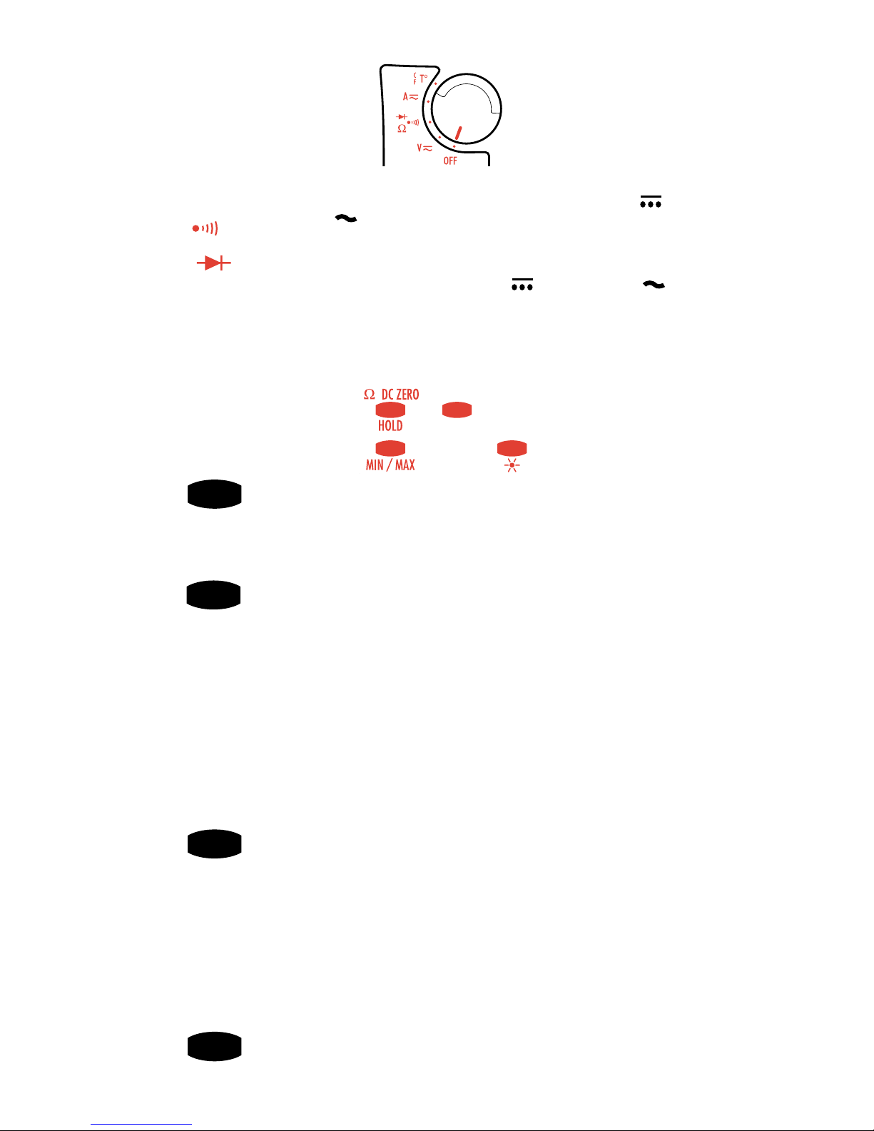
Dodatkowe klawisze funkcyjne
ZóLTY
W połozeniu V lub A, pozwala na przełączanie się z pomiarów prądu
zmiennego na stały.
W połozeniu Ω pozwala na przejście od pomiarów ciagłości
połączeń do pomiarów rezystancji i testu diod.
W połozeniu T° pozwala na przełączanie pomiędzy skalą °C i °F.
NIEBIESKI
HOLD/W/DC Zéro - Cztery rózne funkcje :
1- Krótkie naciśnięcie przycisku blokuje wyświetlacz. Ponowne
naciśniecie powoduje odblokowanie wyświetlacza.
2- Krótkie naciśnięcie przycisku HOLD, a następnie przycisku
MIN/MAX powoduje wstępną selekcję trybu MIN/MAX. Jeśli
aparat jest włączony, kolejne naciśnięcie przycisku HOLD
uruchamia tryb MIN/MAX.
3- Długie naciśnięcie przycisku HOLD umozliwia automatyczną
kompensację rezystancji przewodów. Aby dokonać
kompensacji, nalezy zewrzeć przewody podłączone do
aparatu przy włączonej funkcji pomiarów ciągłości i rezystancji.
4- Długie naciśnięcie przycisku pozwala na automatyczną
kompensację zera dla funkcji amperomierza DC.
CZARNY
MIN/MAX Kolejne krótkie naciśnięcia tego klawisza uruchamiają
następujące funkcje:
1- naciśnięcie: Uruchomienie trybu MIN/MAX; wyświetlenie
wartości PEAK (wartość szczytowa) (tylko w woltach lub
amperach, w innych przypadkach wyświetlana jest wartość
MAX
)
2- naciśnięcie : Wyświetlenie wartości MAX
3- naciśnięcie : Wyświetlenie wartości MIN
4- naciśnięcie : Powrót do wartości PEAK (wartość skuteczna,
w przeciwnym wypadku wyświetlana jest wartość MAX)
Dłuzsze przytrzymanie przycisku : wyjście z trybu MIN/MAX
(mozna opuścić tryb w dowolnym momencie).
ZIELONY
Krótkie naciśnięcie: podświetlenie wyświetlacza. Samoczynne
zgaśnięcie po 2 minutach.
Dłuzsze przytrzymanie przycisku : wyświetlenie stanu
naładowania baterii, wyrazone w godzinach.
Przełącznik obrotowy 5 funkcyjny
OFF = Aparat wyłączony (oszczędność baterii).
V DC/AC= Woltomierz lub pomiar napięcia elektrycznego stałego lub
zmiennego do 600 V przy wysokiej impedancji.
Ω
= Test dźwiękowy ciągłości połączeń dla rezystancji R ≤ 40 Ω i
pomiar rezystancji do 4 kΩ.
= Test diod.
A DC/AC = Pomiar prądu elektrycznego stałego lub zmiennego za
pomocą szczęk, do 400 A.
T° = Pomiar temperatury wewnętrznej i zewnętrznej za pomocą sondy
termoparowej (Adaptor i sondy patrz rozdział Części zamienne).
.
.
.
.
.
.
.
.
.
.
Page 33

33
Odczyt wyświetlacza
Jeśli funkcja zostaje uaktywniona, zapala się odpowiedni symbol.
Zuzycie baterii
PEAK Dla funkcji V lub A w trybie MIN/MAX, Jeśli wywołamy wartość PEAK.
MAX Wskazuje wartość maksymalną w trybie MIN/MAX.
MIN Wskazuje wartość minimalną w trybie MIN/MAX.
HOLD Ostatnia odczytana wartość zostaje zapisana do pamięci.
AC Biezący pomiar jest wykonywany dla prądu zmiennego (symbol migota
Jeśli na szczypcach tryb został wybrany automatycznie, Jeśli tryb
wybrano ręcznie, symbol jest stały)
DC Biezący pomiar jest wykonywany dla prądu stałego (symbol migota
Jeśli na szczypcach tryb został wybrany automatycznie, Jeśli tryb
wybrano ręcznie, symbol jest stały)
+ lub -
Wskazuje polaryzację dla pomiarów prądu stałego i wartości szczytowej PEAK.
Test diod półprzewodnikowych.
T° INT Pozycja przełącznika obrotowego na T° lub przerwane połączenie
sondy termoparowej i gniazda lub bez podłączania sondy (pomiar
temperatury wewnętrznej)
T° EXT
Pozycja przełącznika obrotowego na T° lub prawidłowe połączenie
sondy termoparowej do gniazda
Aparat funkcjonuje bez przerw (usunięcie funkcji automatycznego
zatrzymania pracy)
Stały : Jeśli została wybrana funkcja pomiaru ciągłości połączeń
Migoczący : Jeśli została wybrana funkcja V-Live.
Kombinacje przycisków
Modyfikacja progu sygnału dźwiękowego «BIP» przy pomiarze
ciągłości połączeń : Przytrzymać zółty przycisk i przekręcić przełącznik
obrotowy z pozycji OFF na Ω. Regulacja jest mozliwa w zakresie od 1Ω do
40Ω poprzez kolejne naciśnięcia zółtego przycisku. Po wybraniu wartości,
uruchomić przełącznik w celu jej zapisania.
Usunięcie automatycznego wyłączania : Przytrzymać przycisk HOLD i
przekręcić przełącznik obrotowy z pozycji OFF na Ω .
Usunięcie funkcji V-Live : Przytrzymać przycisk HOLD i przekręcić przełącznik
obrotowy z pozycji OFF na V.
Data ostatniego pomiaru : Przytrzymać przycisk MIN/MAX i przekręcić
przełącznik obrotowy z pozycji OFF na V.
Wyświetlenie wersji oprogramowania wewnętrznego : Przytrzymać
przycisk HOLD i przekręcić przełącznik obrotowy z pozycji OFF na A. Wersja
oprogramowania jest wyświetlana przez 2 sekundy, następnie podświetlane
są wszystkie segmenty wyświetlacza.
Ustawienie konfiguracji standardowej : Przytrzymać zółty przycisk i
przekręcić przełącznik obrotowy z pozycji OFF na A.
Konfiguracja standardowa : poziom BIP : 40 Ω
automatyczne zatrzymanie pracy miernika
funkcja V-Live
jednostka temperatury : °C.
.
.
.
.
.
.
.
.
Podłączenie przewodów pomiarowych do miernika
Końcówkę czarnego przewodu nalezy umieścić w gnieździe oznaczonym «COM»
Końcówkę czerwonego przewodu nalezy umieścić w gnieździe oznaczonym «+».
.
Page 34
34
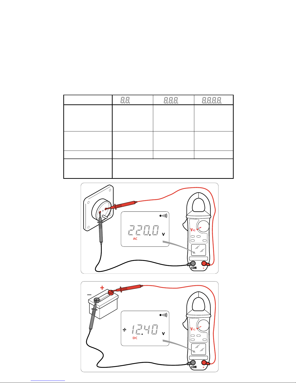
Pomiar napięcia stałego lub zmiennego
Ustawić przełącznik obrotowy na pozycji woltomierza V.
Podłączyć końcówki przewodów pomiarowych równolegle do mierzonego obwodu.
Zmiana funkcji i wybór między napięciami AC/DC są automatyczne.
Dla V DC wyświetlacz wskazuje OL
----powyzej +600V
OL
-----
powyzej –600V.
OL powyzej 900V wartości szczytowej.
Dla V AC, powtarzający się sygnał dźwiękowy informuje, ze mierzone
napięcie jest wyzsze od zgodnego z normami bezpiecznego dla uzytkownika
napięcia, lub 30V AC (45V DC lub wartość szczytowa) (funkcja V-Live)
Zakres wyświetlania V V V
Zakres pomiarów 0,20 – 39,99 V 40,0 – 399,9 V
400 – 600 V DC
400 –900 V
wartość szczytowa
Dokładność 1% odcz.
+
-
5
1% odcz.
+
-
2 1% odcz.
+
-
2
punktow punkty punkty
Rozdzielczość 10 mV 0,1 V 1 V
Impedancja 1 MΩ
wejściowa
.
.
.
.
.
.
.
Page 35
35
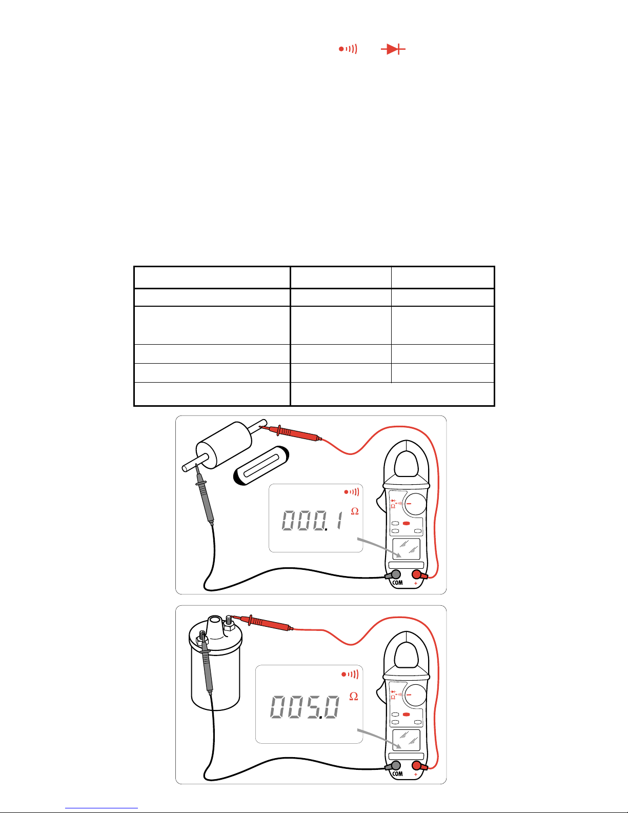
Pomiar ciągłości połączeń i rezystancji
Ustawić przełącznik obrotowy na pozycję
Ω
Kontrola obwodów jest wykonywana za pomocą końcówek przewodów
pomiarowych. Sygnał dźwiękowy ciągłości będzie aktywny dla rezystancji ≤
od progowych wybranych podczas konfiguracji aparatu (standardowo 40 Ω).
REZYSTANCJA
Znajdując się w połozeniu Ciągłość, nacisnąć zółty przycisk (funkcje
dodatkowe), aby wybrać funkcję Rezystancja.
Kontrola obwodów jest wykonywana za pomocą końcówek przewodów
pomiarowych.
Przełączanie funkcji jest automatyczne.
Przekroczenie wartości jest wskazywane na wyświetlaczu za pomocą symbolu OL.
Mozliwość kompensacji rezystancji przewodów poprzez dłuzsze naciśnięcie
HOLD i zwarcie przewodów.
Zakres wyświetlania 400 Ω 4000 Ω
Zakres pomiarów 0,0 – 399,9 Ω 400 – 3999 Ω
Dokładność 1,5 odcz.
+
-
2 1,5 odcz.
+
-
2
punkty punkty
Rozdzielczość 0,1 Ω 0,1 Ω
Napięcie w otwartym obwodzie
3,2 V 3,2 V
Ochrona
500 V AC lub 750 V (DC lub wartości szczytowej)
.
.
..
Page 36
36
1
0
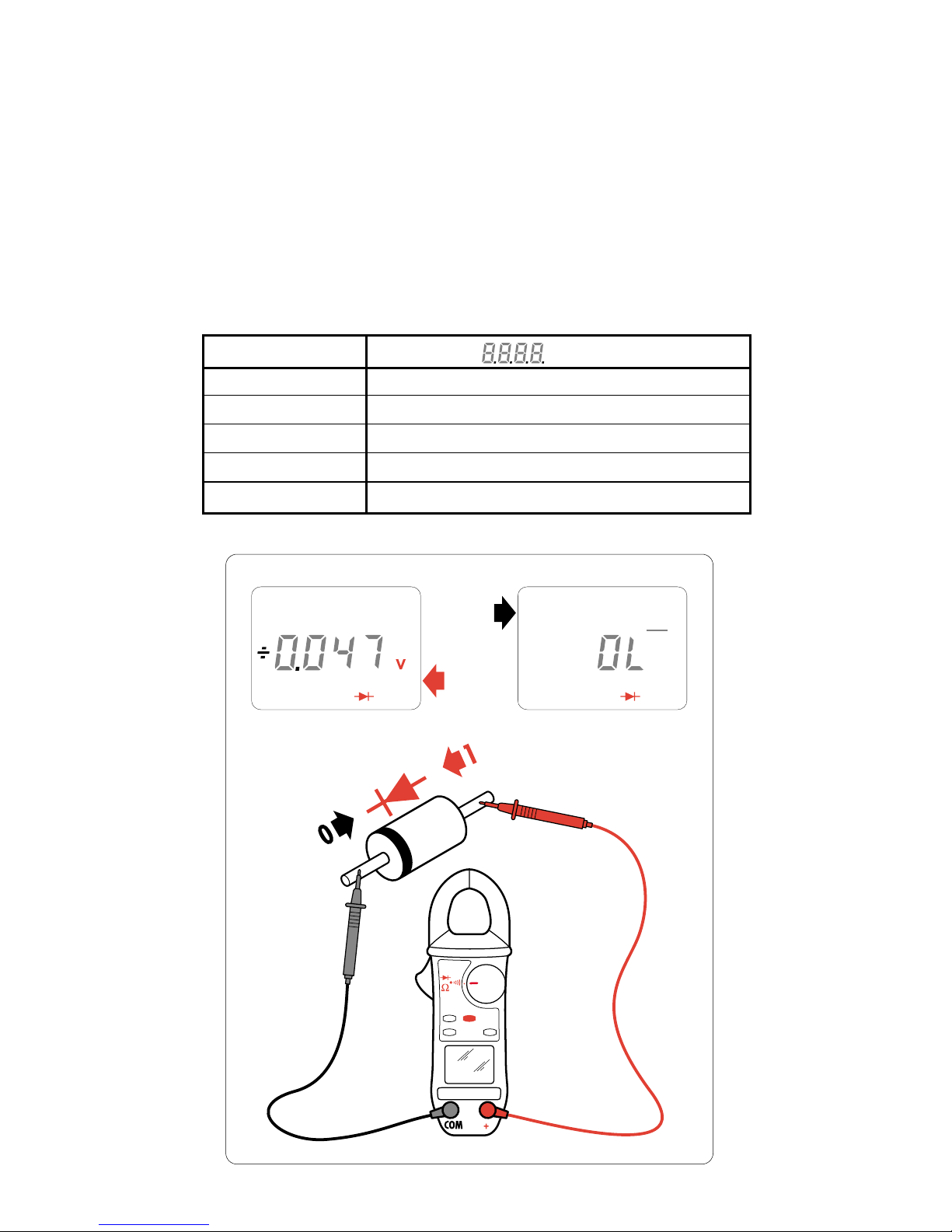
Test diod półprzewodnikowych
Znajdując się w połozeniu Rezystancja, nacisnąć zółty przycisk (funkcje
dodatkowe), aby wybrać funkcję Test diod.
Kontrola obwodów jest wykonywana za pomocą końcówek przewodów
pomiarowych.
Wyznaczenie napięcia przewodzenia złącza diody : sygnał akustyczny dla
wartości < 0,050 V.
Nieprawidłowa polaryzacja diody : na wyświetlaczu pojawia się symbol
przepełnienia OL
-----
Zakres wyświetlania V
Zakres pomiarów 0 – 3,999 V
Prąd probierczy 500 µA
Dokładność 1,5 odcz.
+
-
2 punkty
Rozdzielczość 0,001 V
Ochrona 500 V AC lub 750 V (DC lub wartości szczytowej)
..
Page 37
37
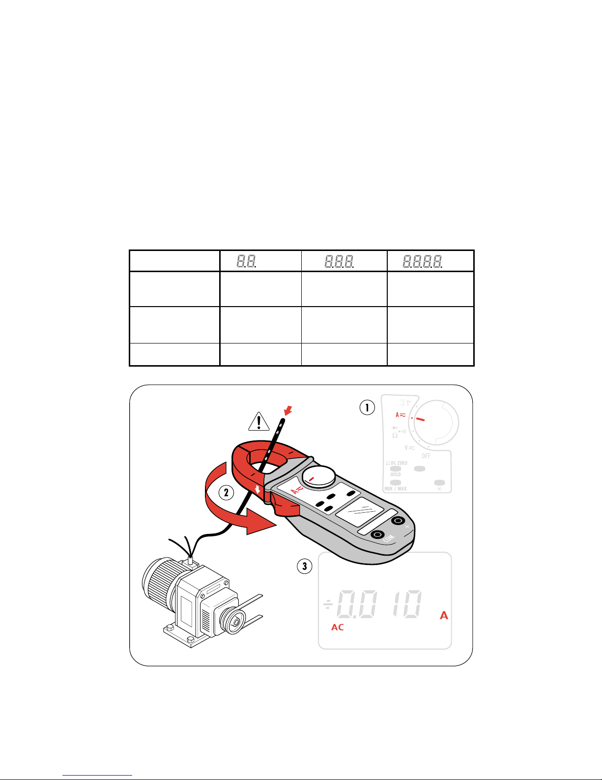
Pomiar prądów stałych i zmiennych
Ustawić przełącznik obrotowy na pozycję amperomierza A.
Nacisnąć dźwignię po lewej stronie miernika aby otworzyć szczęki miernika
i objąć nimi przewód.
Opuścić dźwignię i upewnić się, czy przewód jest prawidłowo połozony
między szczękami miernika.
Przełączanie funkcji i wybór AC/DC są wykonywane automatycznie.
Dla DC, prąd szczątkowy moze być skorygowany poprzez naciśnięcie
przycisku HOLD.
Dla natęzenia DC, prąd maksymalny wynosi 400 A.
Dla A DC wyświetlacz wskazuje OL
-----
powyzej +399,9 A
OL
-----
powyzej –399,9 A.
Dla A AC wyświetlacz wskazuje OL
powyzej 600 A wartości szczytowej.
Zakres wyświetlania A A A
Zakres pomiarów 0,20 – 39,99 A 40,0 – 399,9 A 400–600A
wartość szczytowa
Dokładność 1,5% odcz.
+
-
10 1,5% odcz.
+
-
2 1,5% odcz.
+
-
2
punktów punkty punkty
Rozdzielczość 10 mA 0,1 A 1 A
.
.
.
.
.
.
Pomiar temperatury
Bez sondy
Wyświetlona temperatura jest temperaturą miernika i odpowiada
temperaturze otoczenia po stabilizacji termicznej.
Na wyświetlaczu pojawia się symbol T° INT.
Page 38
38
Pomiar temperatury
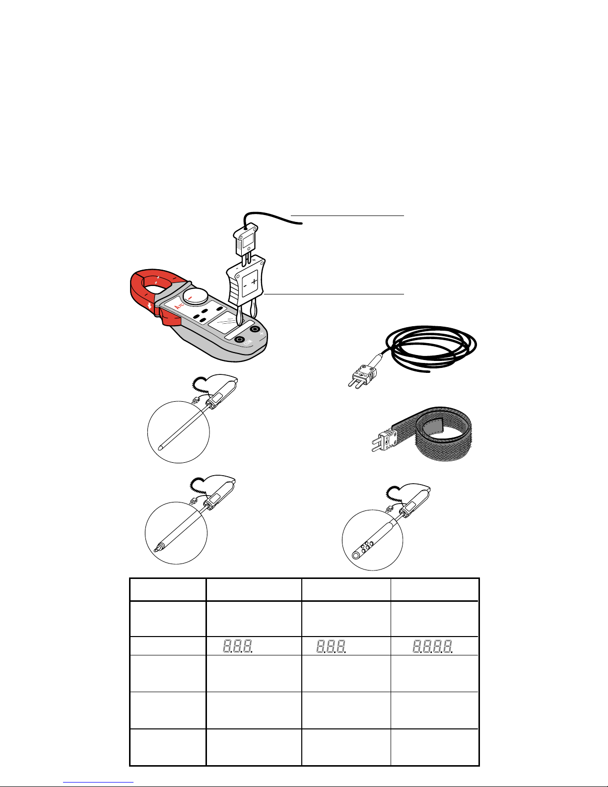
Za pomocą sond (Adaptor i sondy jako wyposazenie dodatkowe)
Podłączyć adaptor termoparowy do obu gniazd wejściowych miernika
zwracając uwagę na bieguny (- do gniazda COM i + do gniazda +).
Do adaptora podłączyć wybraną sondę.
712-01 Adaptor
DX.12-06 Sonda giętka
DX.12-08 Sonda «bransoletkowa»
DX.12R Przedłuzacz (uzywany z sondą «bransoletkową»)
DX.12-11 Sonda igłowa standardowa
DX.12-15 Sonda dotykowa
DX.12-17 Sonda powietrzna
Na wyświetlaczu pojawiają się symbole T° EXT.
.
.
.
Temperatura wewnętrzna Temperaturazewnętrzna Temperatura wewnętrzna
Typ sondy układ scalony Sonda termoparowa Sonda termoparowa
typu K typu K
Zakres wyświetlania °C °C °C
Zakres pomiarów -10°C do +50°C 50,0°C do +399,9°C +400°C do +1000°C
+15°F do +120°F 50,0°F do +399,9°F +400°F do +1800°F
Dokładność
+
-
1,5 °C 1% odcz.
+
-
1,5 °C 1% odcz.
+
-
1,5 °C
+
-
2,7 °F 1% odcz.
+
-
2,7 °F 1% odcz.
+
-
2,7 °F
Rozdzielczość 0,1 °C 0,1 °C 0,1 °C
0,1 °F 0,1 °F 0,1 °F
DX.12-06
DX.12-08
DX.12-11
DX.12R
DX.12-15
DX.12-17
712-01
DX.12-11
DX.12-15
DX.12-17
DX.12-06
DX.12-08
Page 39
39
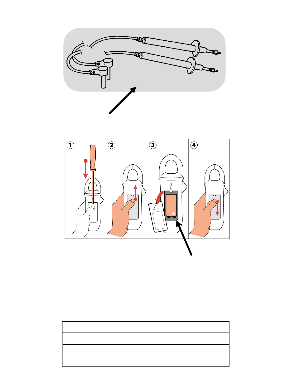
Części zamienne
1
2
712
1 711.19
Zestaw przewodów z końcówkami pomiarowymi
2
bateria 6LF22 Bateria 9 V
712.02
Pudełko
Gwarancja : 1 rok.
Uwaga : Szczęki, akcesoria (okablowanie, pudełko) są częściami
zuzywalnymi i nie są objęte gwarancją.
Page 40

40
FACOM Belgique S.A/NV
Weihoek 4
1930 Zaventem
BELGIQUE
& : (02) 714 09 00
Fax : (02) 721 24 11
FACOM NORDEN A/S
Navervej 16B
7451 SUNDS
DANMARK
& : (45) 971 444 55
Fax : (45) 971 444 66
FACOM GmbH
Postfach 13 22 06
42049 Wuppertal
Otto-Wells-Straße 9
42111 Wuppertal
DEUTSCHLAND
& : (0202) 270 63 0
Fax : (0202) 270 63 50
FACOM Herramientas SRL
Poligono industrial de Vallecas
C/.Luis 1°, s/n-Nave 95 - 2°Pl.
28031 Madrid
ESPAÑA
& : (0034) 91 778 21 13
Fax : (0034) 91 778 27 53
USAG Gruppo FACOM
Via Volta 3
21020 Monvalle (VA)
ITALIA
& : (0332) 790 111
Fax : (0332) 790 602
POLOGNE
FACOM Oddzial w Warszawie
ul.Marconich 9 m.3
02-954 Warszawa
POLSKA
& : (0048 22) 642 71 14
Fax : (0048 22) 651 74 69
BELGIQUE
LUXEMBOURG
DANMARK
FINLAND
ISLAND
NORGE
SVERIGE
DEUTSCHLAND
ESPAÑA
PORTUGAL
ITALIA
POLOGNE
NEDERLAND
SINGAPORE
FAR EAST
SUISSE
ÖSTERREICH
MAGYARORSZAG
CESKA REP.
UNITED
KINGDOM
EIRE
UNITED
STATES
FRANCE
&
INTERNATIONAL
FACOM Gereedschappen BV
Kamerlingh Onnesweg 2
Postbus 134
4130 EC Vianen
NEDERLAND
& : (0347) 362 362
Fax : (0347) 376 020
FACOM Tools FAR EAST Pte Ltd
15 Scotts Road
Thong Teck Building #08.01.02
Singapore 228218
SINGAPORE
& : (65) 732 0552
Fax : (65) 732 5609
FACOM S.A./AG
12 route Henri-Stéphan
1762 Givisiez/Fribourg
SUISSE
& : (4126) 466 42 42
Fax : (4126) 466 38 54
FACOM - UK
Churchbridge Works
Walsall Road
CANNOCK
STAFFORDSHIRE WS11 3JR
UNITED KINGDOM
& : (01922) 702 150
Fax : (01922) 702 152
FACOM TOOLS Inc.
3535 West 47th Street
Chicago Illinois 60632
U.S.A.
& : (773) 523 1307
Fax : (773) 523 2103
Société FACOM
6-8, rue Gustave Eiffel B.P.99
91423 Morangis cedex
FRANCE
& : 01 64 54 45 45
Fax : 01 69 09 60 93
http://www.facom.fr
 Loading...