

Facit N4000 User Manual
Facit N4000
Punch/Reader-Punch
User's Manual
C o n t e n t s P a g e
1 I n t r o d u c t i o n / H o w t o g e t s t a r t e d 3
2 D e s i g n a n d C o n s t r u c t i o n 1 1
3 O p e r a t i o n 1 5
4 K e y b o a r d C o n t r o l s 1 9
5 P r o g r a m M o d e 2 3
6 I n t e r f a c e c o n n e c t i o n s 3 3
7 T e c h n i c a l S p e c i fi c a t i o n 3 5
Appendix 1 (C o n v e r s i o n c h a r t , A S C I I to Tel e x )
Appendix 2 (C o n v e r s i o n c h a r t , A S C I I to Tel e x )
Appe n dix 3 (Conver s ion ch a rt,ASC I I to EI A)
App endix 4 (C onve rsion cha rt,AS CII to RS 358)
Appendix 5 (Code co nve rsi on)
Appe ndix 6 (Tel ex Tape F ormat t ing)
Appendix 7 (Test Mode)
Copyright, Facit AB Sweden, 1989.01/3500
1 Introduction
The Facit N4000 comes in two versions, a paper
tape punch and a reader/punch combination.
The paper tape punch, punches 5 to 8 track tapes.
Five track is normally used to punch telextapes
and eight track mostly for punching NC-programs.
The punching speed is 30, 62 or 75 characters
per second, operator selectable.
The reader/punch combination can read and punch 5
to 8 track tapes.
The reading speed is 200/500 characters per
second, operator selectable.
Both units are designed as stand alone units for
table top mounting. Two standard I/O ports are
available with CCITT V.24/RS-232-C serial
interface.
Facit N4000 has a buffer of~ 9 K capacity.
Code conversion can be performed. The codes
included are the two used NC codes ISO and EIA and
the national versions of the telexcode.
A small keyboard and status display are
inc orpor ated at th e top of the unit; with this all
operating system parameters may be quickly and
easily entered with no necessity to change PC
board DIP switch settings. The status display
clearly indicates the u n i t ' s c u r r e n t ope r a t i n g
status, and also shows simple error messages.
How to get started
Mains connection
- Check that the mains voltage selector on the
rear panel, see Fig. 6.1, shows the actual
mains vo ltage.
- Connect the mains cord to rear panel mains inlet
and to the mains.
- Switch the ON/OFF switch on the rear panel to
ON.
- Check that the status display, see Fig. 4.1,
shows OFF.
Punching
Punch tape loading
Load the tape according to section 1.2 Punch Tape
Loading.
Punching instruction
- Connect the NC/Computer cable plug to the
CHANNEL 1 I/O PORT connector on the rear panel,
see Fig.6.1.
- Depress the key ON L on the operator keyboard.
The status display shows LINE.
- Start the punching from the NC/Computer.
- Tear off the tape when the punching is ready.
If required, blank tape can be fed by depressing
OFF L and FEED before tearing off the tape.
Note
The data transmission should be made at 600 bit/s.
Reading
Reader Tape Loading
Load the tape according to section 1.5 Reader Tape
Loading.
Reading instruction
- Depress the ON L key on the operator keyboard.
The status display shows LINE.
- Clear the NC/Computer for reading.
- Depress the START key to start the reading.
- Depress the STOP key to stop the reading.
- Depress the START key to restart the reading.
Note
The data transmission should be made at 600 bit/s.
Because reading is faster than transmission, the
reader can stop before the whole tape is read. The
reader will res tart automatically and con tinue
until the whole tape is read.
The tape can be run quickly through the reader
either forwards or reverse, without data being
read, by depressing the FF or FB key respectively.
The equipment must be off line.
When data is sent over the line, by reading or
punchi n g , a sp e c ial s ign ( a t re a ding, at
punching) is shown in the display to indicate
communication. At punching the display returns to
"Line", when data has been sent. At reading, when
the communication stops by any reason, the display
shows "data" if there is data in the buffer. The
buffer can be cleared by pressing the Stop key <*>
and the display goes back to "Line".
If punching is started after reading and there
still i s data in t h e buffer, the buffer i s
automatically cleared. By sending to N4000 for
punching, the display switches from "data", if the
buffer is not cle ared, to the specia l l ine
communication sign.
Ta pe c op y in g
Tap e c o pyin g i nstr u c tion
- Depress the OFF L key on the operator keyboard.
The status display shows OFF.
- Depress the COPY key.
The status display shows COPY.
- Put the tape in the reader.
- Depress the START key.
Copying will start.
- Depress the OFF L and ON L keys when copying is
finished.
If the raeder stops during copying, it is due to
the fact that the reader is faster than the punch.
The copying will restart automatically and
continue until the whole tape is copied.
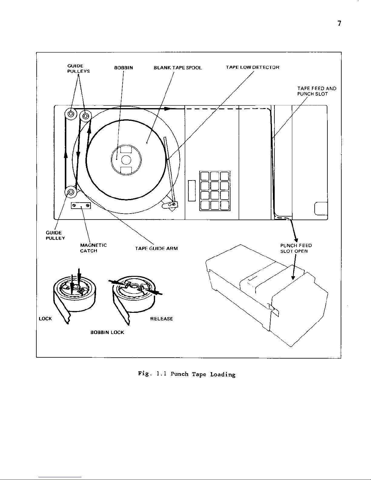
1.1 Punch Tape Handling
The tape path through the punch is shown in Fig.
1.1. The blank tape leaves the spool and passes
around a pulley on the tape guide arm. The guide
arm applies a progressively acting brake which
operates on the tape bobbin. This operates to
ensure that tape fed through the punch is
maintained at a constant tension to ensure
accuracy and consistency of punching.
Tape Low and Tape End
When the punch tape supply is low, the error
message 'Lo' appears on the display. When the tape
is exhausted, or if a jam occurs in the feed
mechanism, the message 'Err' blinks on and off on
the display.
1.2 Punch Tape Loading
With mains power switched OFF, load tape onto the
punch tape holder as follows (see Fig. 1.1).
(1) Move the tape guide arm until it touches the
magnetic catch. This action applies the brake
to the tape bobbin and frees the tape feed and
punch mechanism.
(2) Pull out 2 metres (6 feet) of tape from the
new reel and place the reel onto the bobbin.
(3) Lock the bobbin by pushing the centre section
downwards by hand as far as possible (see Fig
1.1).
(4) Push upwards the two punch opening pegs
(located one at each side of the punch housing
- see Figs. 2.1 and 2.2), and pull forward the
punch assembly to open the tape feed and punch
slot (see Fig. 1.1).
(5) Lead the tape around the guide pulleys and
drop it into the tape feed and punch slot.
(6) Push back the punch assembly to close the tape
feed and punch slot.
(7) Release the tape guide arm from the magnetic
catch.
(8) Switch the power ON and depress the FEED key
unt il the tape is taut , and feeding correct ly
from the spool.
GUIDE
PULLEYS
B O B B I N B L A N K T A P E S P O O L T A P E L O W D E T E C T O R
□ DD
DDD
odd
ODD
TAPE FEED AND
PUNCH SLOT
i
GUIDE
PULLEY
MAGNETIC
CATCH
TAPE GUI DE AR M
LOCK ELEASE
BOBBIN LOCK
Fig. 1.1 Punch Tape Loading

8
1.3 Punching Accuracy
The accuracy of punching can be checked by using
the Facit template part no. 1114 00 50-00/0 as
shown in Fig. 1.2. It is recommended that this
check is carried out approximately every 50th tape
reel used.
(1) Lay the punched tape on the template as shown
in Fig. 1.2, with a feed hole accurately
centered on the leftmost vertical line.
(2) Examine the 50th feed hole on the rightmost
v e rt i ca l lin e . I f t h is l in e is v is i bl e wi t hi n
the hole, (i.e. within +-0.5 %), the punch
accuracy is acceptable.
(3) I f the v e r t ical l i n e is n o t visib l e (i.e.
outside +-0.5 %) the punch mechanism requires
servicing.
c
- 50 Characters = 127mm = 5 inches -
I H'il l.t-H *-+]
I ' t
t1-rt'H-4~f
T*T
—t-l 4 -I- +4- +-h+ 4—n
FACIT
FEED HOLE
CENTRED
ON GRID
e
i
e
©
0 5 O T H F E E DHOL E (ACCURATE)
O - 0 . 5% I AC C EP TA B L E
& L I M I T S
+ 0.5% I
Fig. 1.2 Check Intercharacter Spacing
1.4 Reader Tape Handling (Facit N4000 Combination
only)
The tape path through the reader is shown in Fig.
2.5. The tape passes under the entry guide wire,
through the tape width selector (adjustable to
suit 5, 6/7 and 8 channel tapes), past the reader
head and over the drive sprocket. The drive
sprocket teeth engage in the tape feed holes to
pull the tape past the head.
An indicator lamp on the reader head is lit to
show that the optical reader lamp is on.
The tape can be run quickly through the reader
either forwards or backwards, without data being
read, by depressing the FF or FB key
respectively.
Reader Error
A malfunction of the tape reader mechanism stops
the transmission of data and the message 'Err'
blinks on and off on the display.
To clear, press <*> key.
10
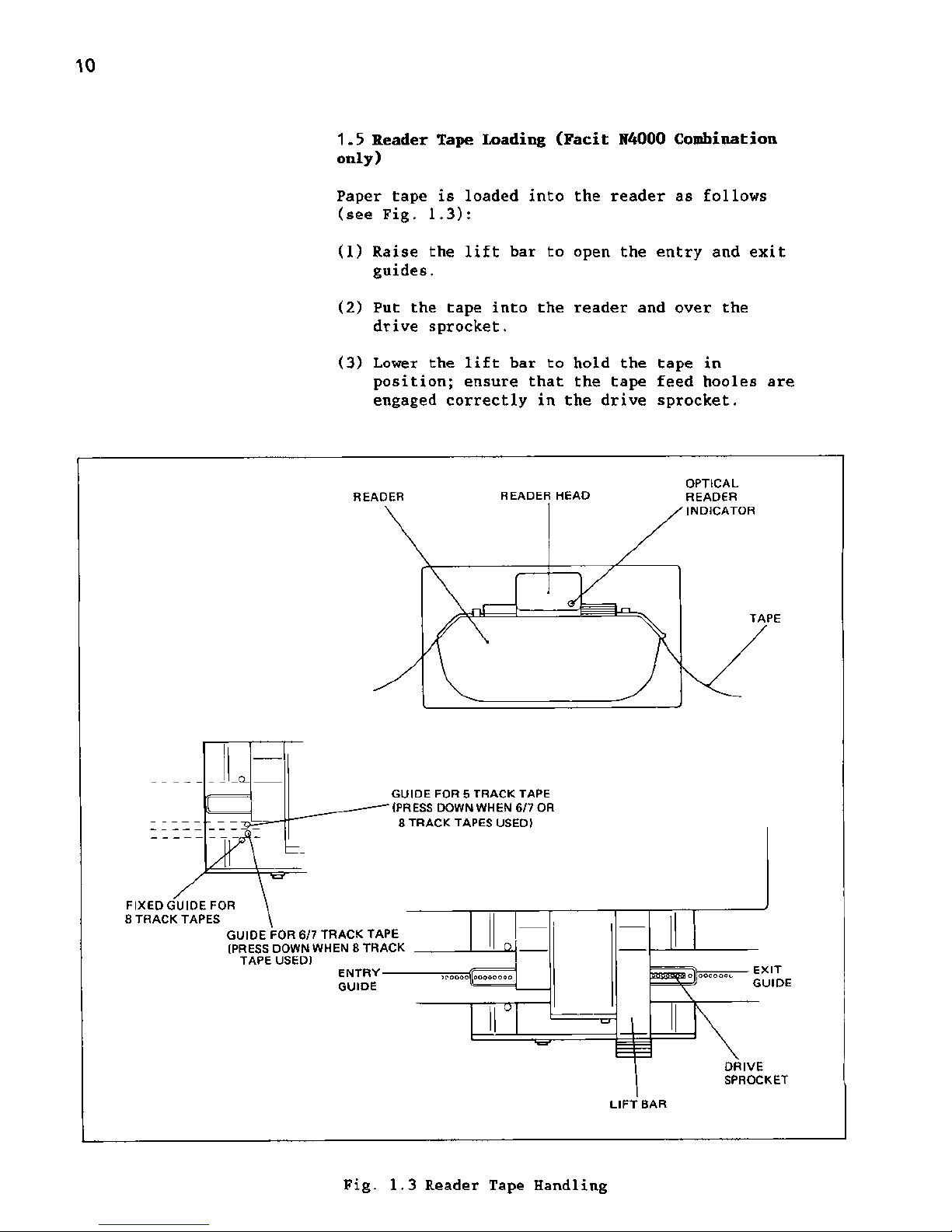
1.5 Reader Tape Loading (Facit N4000 Combination
only)
Paper tape is loaded into the reader as follows
(see Fig. 1.3):
(1) Raise the lift bar to open the entry and exit
guides.
(2) Put the tape into the reader and over the
drive sprocket.
(3) Lower the lift bar to hold the tape in
position; ensure that the tape feed hooles are
engaged correctly in the drive sprocket.
READER READER HEAD
OPTICAL
READER
INDICATOR
TAP E
GUIDE FOR 5 TRACK TAPE
(PRESS DOWN WHEN 6/7 OR
8 TRACK TAPES USED)
FIXED GUID E FOR
8 TRACK TAPES
GUIDE FOR 6/7 TRACK TAPE
(PRESS DOWN WHEN 8 TRACK
TAPE US ED)
ENTRYGUIDE
^cooooloooooooo
olooooooo
EXIT
GUIDE
DRIVE
SPROCKET
LIFT BAR
Fig. 1.3 Reader Tape Handling
11
2 Design and Construction
2.1 Brief Description
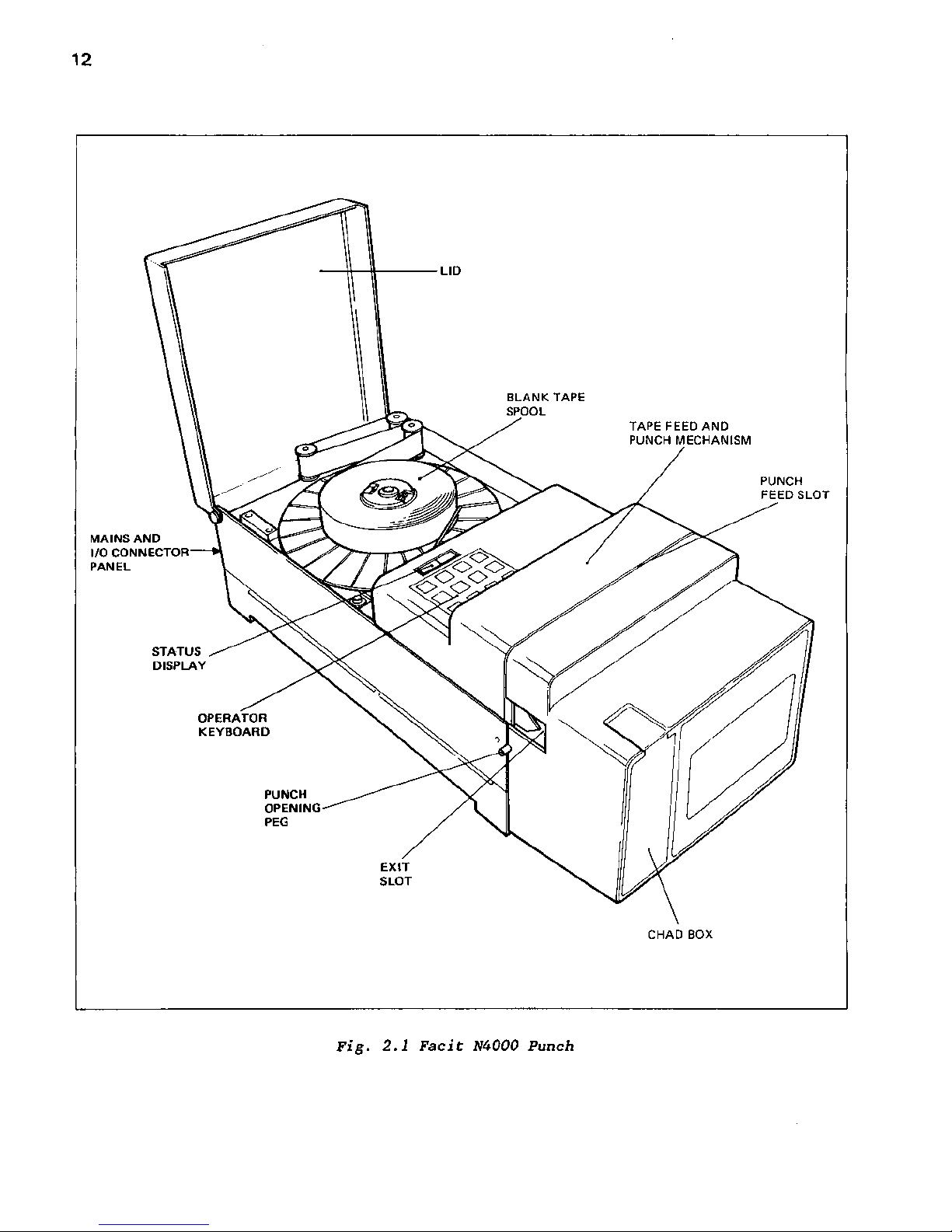
The Facit N4000 is shown in Fig. 2.1. The blank
tape is contained on a standard spool at the top
rear of the unit, with the tape feed and punch
mechanism housed under a cover towards the front
of the machine. A semi-transparent lid covers the
tape spool during normal operation, and the amount
of tape left on the spool can easily be seen
without raising the lid.
The reader head is mounted at the front of the
unit next to the chad box.
The punched tape emerges from the exit slot at the
left of the unit; no special arrangement is
included for handling the punched tape.
A tape cutter is fitted in the punched tape exit
slot. The tape i s t orn off against this cutte r to
leave a 'V at the end of the tape; this enables
the start and finish of the tape to be correctly
identified.
The chad box is located at the front left of the
unit and may be removed by pulling it out from the
top.
The operator's keyboard and status display are
situated on top of the unit in front of the lid.
The mains ON/OFF switch, supply fuses and I/O
connector are fitted on the rear panel of the
unit.
12
MAINS AND
I/O CONNECTOR
PAN EL
STATUS
DISPLAY
OPERATOR
KEYBOARD
PUNCH
OPENING
PEG
EXIT
SLOT
TAPE FEED AND
PUNCH MECHANISM
PUNCH
FEED SLOT
CHAD BOX
Fig. 2.1 Facit M000 Punch
13
MAINS AND
I/O CONNECTOR
PAN EL
STATUS
DISPLAY
TAPE FEED AND
PUNCH MECHANISM
PUNCH
FEED SLOT
OPERATOR
KEYBOARD
PUNCH
OPENING
PEG
EXIT SLOT
CHAD BOX
TAP E
READER
HEAD
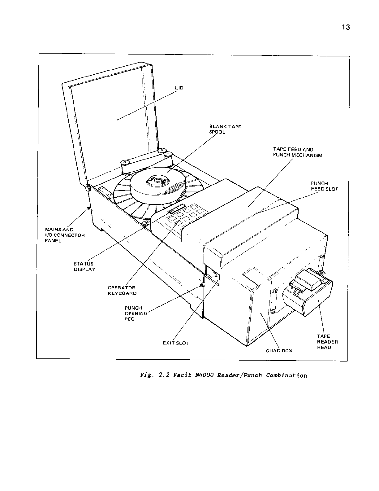
Fig. 2.2 Facit N4000 Reader/Punch Combination
15
3 Operation
The unit is intelligent and all programming
functions are performed by entries made on the
built-in keyboard.
All program parameters are held in RAM, and a
battery is incorporated on the interface board to
preserve the memory contents when the unit is
switc h ed o ff. The batte r y c a pacity is suffici e nt
to retain the memory contents for several years.
3.1 Punch buffer
The overall operation of the punch, and the
control of incoming data, is performed by the
buffer. The buffer's to tal capac ity is*v9 K. This
capacity is shared between Channels 1 and 2
according to the buffer stop address selected for
channel 1, in the Program step 12. Each buffer
accepts data from its source until full; a n
instruction is then sent to the source to stop the
transmission. The minimum size for either buffer
is 256 characters.
The required code conversion of the incoming data
is performed prior to reading into the buffer;
data in the buffer is therefore always in the
correc t version for direct punching out .
3.2 Punching out data
Whichever channel has assumed priority for
incoming data keeps this priority when punching
data.
Data transfer from buffer to punch is controlled
and selected in the Program mode (see section 5).
3.3 Buffer Status Sign alling
The acceptance of incoming data is controlled by
the Full or Empty status of its associated part of
the buffer.
The buffer Full or Empty condition is indicated
either by X-ON/X-OFF protocol or Ready/Busy status
signall ing, selectable s eparately f or each c hannel
in the Program mode.
3.4 Punch Speed
The punching speed is 30, 62 or 75 characters per
second, operator selectable.
16
3.5 Time Out
If data is sent to both channels simultaneously,
the channel receiving data first assumes priority
and starts punching. An End of Message character
or a Time Out selected in Program mode 10 can
change priority to the other channel. The Time Out
function is explained fully in Appendix 6.
3.6 Tape Reader (Facit N4000 reader/punch
combination only)
Where a reader is included on the unit, data read
from a punched tape is transmitted via channel 1
or channel 2.
Reading takes place at a speed of 200/500
characters per second, operator selectable.
When the reader is started from the keyboard
(start key) data is always transmitted via channel
1. When the reader is started remote, using the
start reader code, data can be transmitted via
channel 1 or 2 depending on the channel used to
send the start reader code. The channel not
affected by reading can accept data for punching.
If reading is attempted while data for punching
remains in any of the buffers for channel 1 or 2,
reading is inhibited and BUSY is displayed,
reading can start when the existing contents are
punched and the channel buffer is empty.
The reader stops when the Stop key is depressed, a
stop reader code is received (either sent over the
line or read on the tape), or when the tape end is
reached.
The transmission continues until the buffer is
empty even if the reader stops due to any of the
conditions above.
The transmission can be controlled using the
X-0N/X-0FF protocol. Sending the code DC3 will
stop transmission and the code DCl will start
transmission.
17
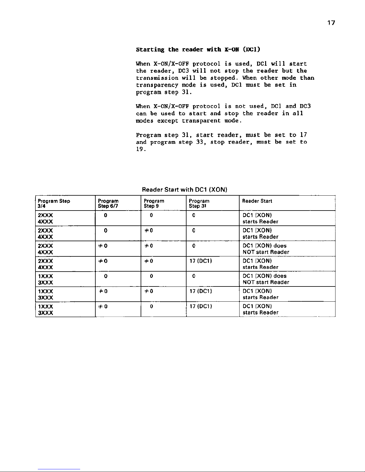
Starting the reader with X-ON (DCl)
When X-ON/X-OFF protocol is used, DCl will start
the reader, DC3 will not stop the reader but the
transmission will be stopped. When other mode than
transparency mode is used, DCl must be set in
program step 31.
When X-ON/X-OFF protocol is not used, DCl and DC3
can be used to start and stop the reader in all
modes except transparent mode.
Program step 31, start reader, must be set to 17
and program step 33, stop reader, must be set to
19.
Reader Start with DC1 (XON)
Program Step
3/4
Program
Step 6/7
Program
Step 9
Program
Step 31
Reader Start
2XXX
4XXX
0 0 0
DC1 (XON)
starts Reader
2XXX
4XXX
0 =£0 0 DC1 (XON)
starts Reader
2XXX
4XXX
=£0 *0 0 DC1 (XON) does
NOT start Reader
2XXX
4XXX
=#0 *0
17(DC1)
DC1 (XON)
starts Reader
1XXX
3XXX
0 0 0 DC1 (XON) does
NOT start Reader
1XXX
3XXX
#0 *0
17(DC1)
DC1 (XON)
starts Reader
1XXX
3XXX
=/=o 0 17(DC1)
DC1 (XON)
starts Reader
 Loading...