

Page 1

4331 EUCALYPTUS AVE. ~~ CHINO, CA 91710
FTS8023 / FTS8046
Dual Steering Stabilizer System
2005-15 Ford F250 & F350 4WD
Part #
Qty
2 FT7006 Steering
1 FT30145BK Axle
2 FT30149 Tie Rod Brackets
1 FT739U Axle U-Bolt
1 FT30312 Hdwr Sub-Assembly Kit
FT30312 Hdw
Part # Description
Qty
4 FT740U Tie Rod U-Bolt
2 FT140357 Shock Stud Kit
1 FT58H Axle u-bolt hardware
8 37160003052 3/8"-16 Nyloc Nut
8 37000005081 3/8" SAE Flat Washer
2 50132001081 1/2"-13 x 2" Hex Bolt
2 50000005081 1/2" SAE Flat Washer
1 FTLOCK Thread Locking Compound
1 FTAS12 Sticker
1 FTREGCARD Registration Card
2 FT8023i Instruction
Description FTS8023
Stabilizer
Bracket
r Sub-Assembly Kit
Sheet
TOOL LIST:
Assorted Metric & Standard Wrenches
Torque Wrench
Measuring Tape
Die Grinder With Cut-Off Wheel
Part #
Qty
2 FTS6604
1 FT30145BK Axle
FT30149 Tie Rod Brackets
2
1
FT739U Axle U-Bolt
1
FT30312 Hdwr Sub-Assembly Kit
FT30312 Hdw
Qty
Part # Description
FT740U Tie Rod U-Bolt
4
FT140357 Shock Stud Kit
2
1
FT58H Axle u-bolt hardware
8 37160003052 3/8"-16 Nyloc Nut
8 37000005081 3/8" SAE Flat Washer
2 50132001081 1/2"-13 x 2" Hex Bolt
2 50000005081 1/2" SAE Flat Washer
FTLOCK Thread Locking Compound
1
1 FTAS12 Sticker
1 FTREGCARD Registration
2 FT8023i Instruction
Description FTS8046
Steering
Stabilizer
Bracket
r Sub-Assembly Kit
Card
Sheet
READ BEFORE BEGINNING INSTALL
READ ALL INSTRUCTIONS THOROUGHLY FROM START TO FINISH BEFORE BEGINNING INSTALLATION.
DO NOT ALTER THE FINISH OF THESE COMPONENTS, EX
PAINTING. CHANGING THE FINISH CAN CAUSE STRUCTURAL FATIGUE OF COMPONENTS.
THIS STABILIZER KIT WILL NOT WORK ON STOCK HEIGHT VEHICLES. IT IS DESIGNED TO WORK ONLY
ON VEHICLES WITH FABTECH LIFT SYSTEMS
THIS SYSTEM WILL ONLY WORK IN CONJUCTION WITH FABTECH 4”, 6”, 8” AND 10” LIFT SYSTEMS.
AMPLE- CHROMING, ZINC PLATING OR
Page 2
Begin Installation:
1. Disconnect the negative terminal on the battery. Park the truck on level ground and set the emergency brake.
2. Locate FT30145 Axle Bracket and FT140357 Shock Stud kits. Attach the stub kits to the two front holes on the
axle bracket and torque to 55 ft lbs. .
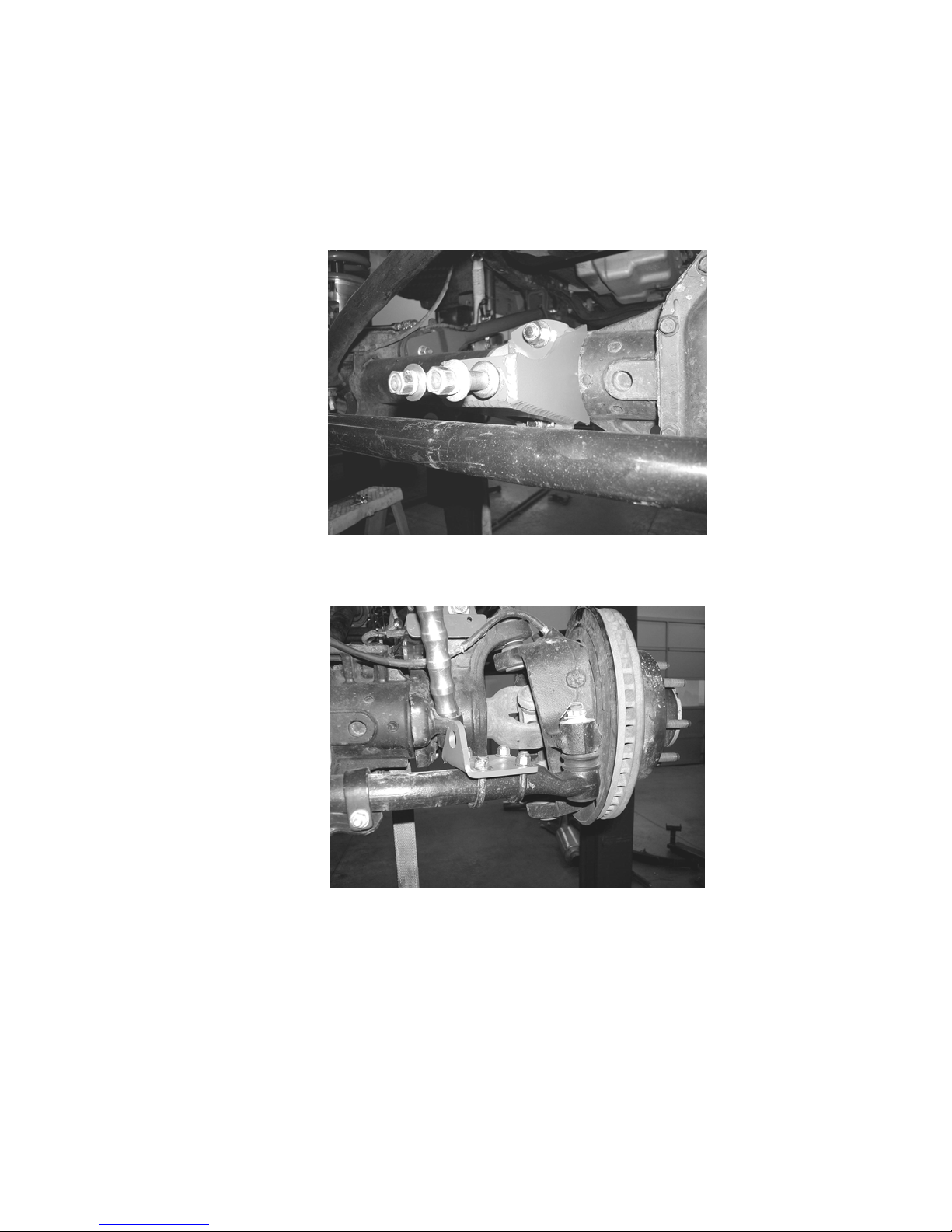
3. Locate FT30145 Axle Bracket with the shock studs installed and place the axle bracket in the center of the axle
posi
tioning it straight forward. Using the supplied FT739U U-Bolt and 5/8” hardware, attach the axle bracket to
the axle. Leave loose at this time. SEE PHOTO BELOW.
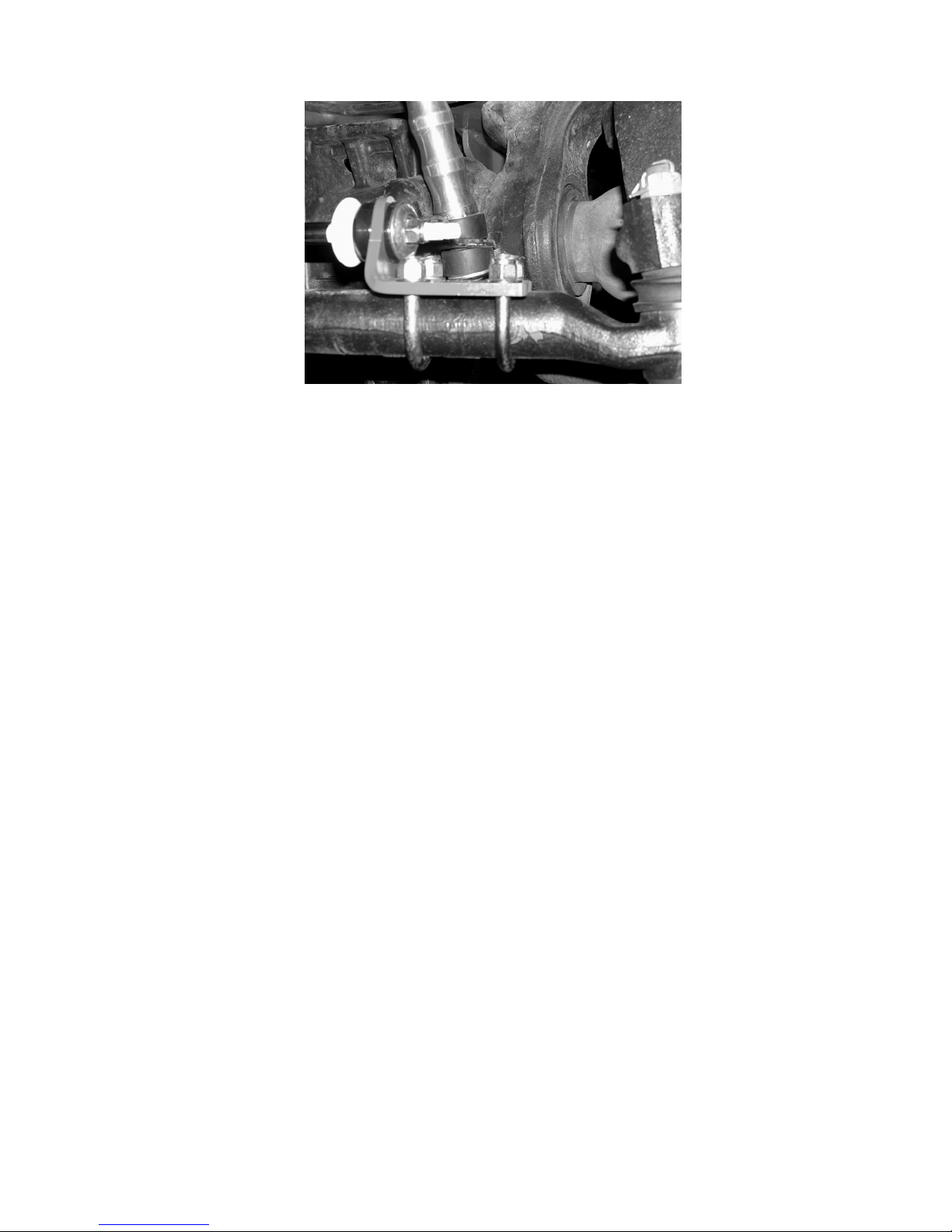
4. Working from the driver side of the truck, locate FT30149 tie rod end bracket and position it 2” from the outer
tie rod end. Using the Supplied FT740U U-Bolt and 3/8” hardware attach the bracket to the tie rod end. Leave
lo
ose at this time. SEE PHOTO BELOW.
Locate FT7006 or FTS6604 Steering Stabilizer and attach it to the stud on the axle bracket using the supplied
5.
hardware along with a small amount of the supplied thread locking compound. Torque bolt to 30 ft. lbs.
6. Ext
end the Steering Stabilizer out 5 ½” and attach the stud end of the stabili
suppl
ied stem bushing and hardware. You may need to move the tie rod end bracket from were it was origin
zer to the tie rod bracket using the
ally
positioned. Tighten the stem hardware until the bushings begin to squeeze out.
7. R
epeat steps four through six on the passenger side of the tr
8. To
rque the Axle Bracket U-Bolt to 80 ft lbs. Torque the Tie Rod bracket U-Bolts to 32 ft lbs with the stab
still extended 5 ½”.
uck.
ilizer
Page 3
9. Once the tie rod u-bolts are torque to 32 ft. lbs. using a die grinder with a cut off wheel, trim the residual length
he u-bolt flesh with the nut. SEE PHOTO BELOW
of t
.
10. Steer the truck fully to the left and right to make sure the steering stabilizers are not bottoming out. Adjust the tie
rod end bracket as needed. Check the clearance of the shock stud end to the u-bolts previously cut for proper
clearance.
11. R
e-torque all the hardware after 200 mile
s.
 Loading...