

Page 1
INSTALLATION INSTRUCTIONS
2005-2015 FORD F250/350 SUPERDUTY 4WD
LEVELING KIT
2”
FT5205i
Page 2
ARTS LIST -
ound.
e the height of your vehicle. This measurement can be
ecorded from the center of the wheel, straight up to the top of
the inner fender lip. Recor
d the measurements below.
- P
2005-2013 FORD F250/350 SUPERDUTY 4WD, 2” LEVELING KIT
FTL5205 2F 2005-2015 F350/350 4WD
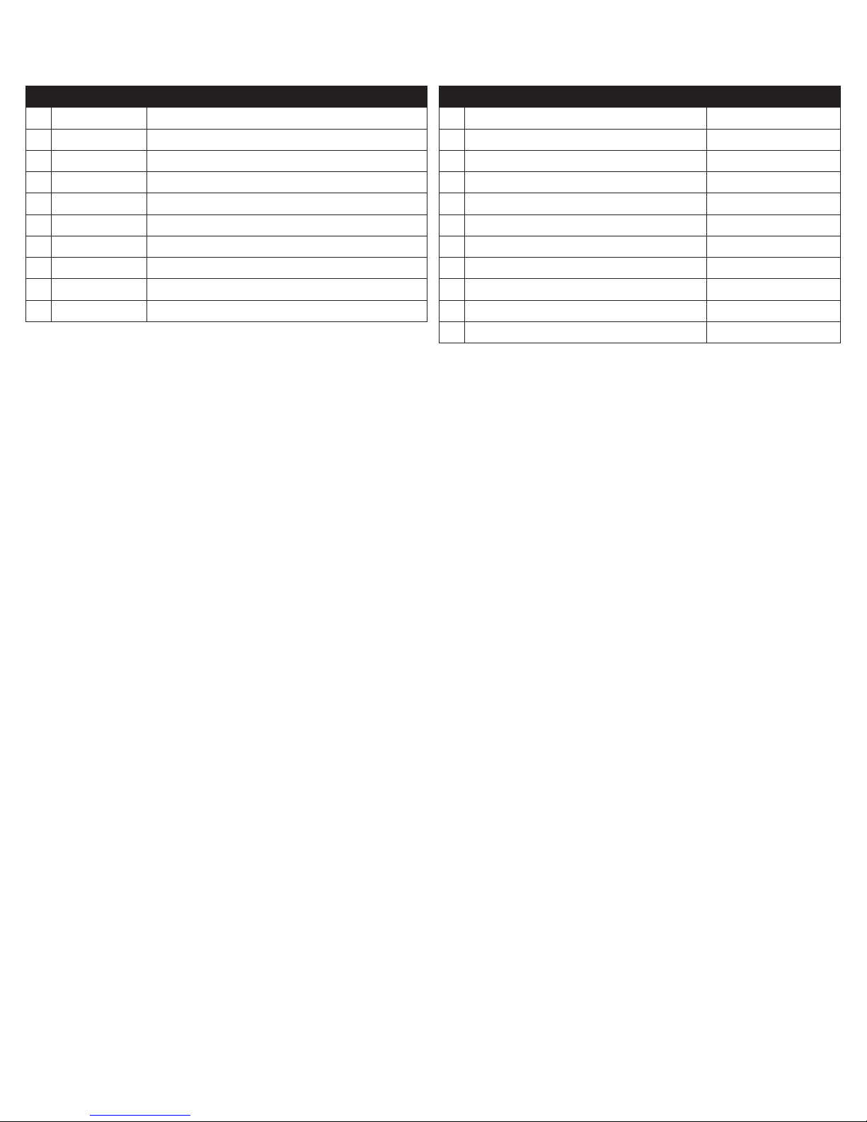
2 FT30162 COIL SPACER 2”
2 FT120 SLEEVE 1.000 X .563 X .310
1 FT30580 SHOCK EXTENSION BRACKET DRIVER
1 FT30581 SHOCK EXTENSION BRACKET PASSENGER
2 FT30171 BRAKE LINE BRACKET
2 FT30172 BRAKE LINE BRACKET (AXLE)
1 FT30586 HARDWARE KIT
1 FT5205i INSTRUCTIONS
1 FTAS12 STICKER FT BLUE 10X4 DIE CUT
1 FTAS16 DRIVER WARNING DECAL
READ THIS BEFORE YOU BEGIN INSTALLATION -
FT30586 - HARDWARE KIT LOCATION
2 M14-2.0 X 80MM HEX BOLT SHOCK EXT.
4 M14 FLAT WASHER
2 M14 X 2.0 NYLOCK NUT
2 5/16-18 X 1 HEX BOLT BRAKE LINE BRACKET
2 5/16-18 NYLOCK NUT
4 5/16” SAE WASHER
2 M14 FLAT WASHER CL 10 ZINC
2 M14-2.0 X 100MM HEX BOLT
4 M8 FLAT WASHER
4 M8-1.25 X 20MM HEX HEAD
1 THREAD LOCKING COMPOUND 2 MIL
Check all parts to the parts list above before beginning installation.
Read all instructions thoroughly from start to finish before beginning the installation. If these instructions are not properly
followed severe frame, driveline and / or suspension damage may occur.
Check your local city and state laws prior to the installation of this system for legality. Do not install if not legal in your area.
Prior to the installation of this suspension system perform a front end alignment and record. Do not install this system if the
vehicle alignment is not within factory specifications. Check for frame and suspension damage prior to installation.
Use the provided thread locking compound on all hardware.
WARNING- Installation of this system will alter the center of gravity of the vehicle and may increase roll over as compared
to stock.
Vehicles that receive oversized tires should check ball joints, uniballs, tie rods ends, pitman arm and idler arm every 25005000 miles for wear and replace as needed.
Required Tools (Not Included)
Basic Hand Tools
Floor Jack
Jack Stands
Assorted Metric and S.A.E sockets, and Allen wrenches
Torque Wrench
Die Grinder w/ Cutoff Wheel or Sawzall
Page 3
- INSTRUCTIONS -
FRONT SUSPENSION
1. Disconnect the negative terminal on the battery. Jack up
the front end of the truck and support the frame rails with
jack stands. NEVER WORK UNDER AN UNSUPPORTED
VEHICLE! Remove the fr
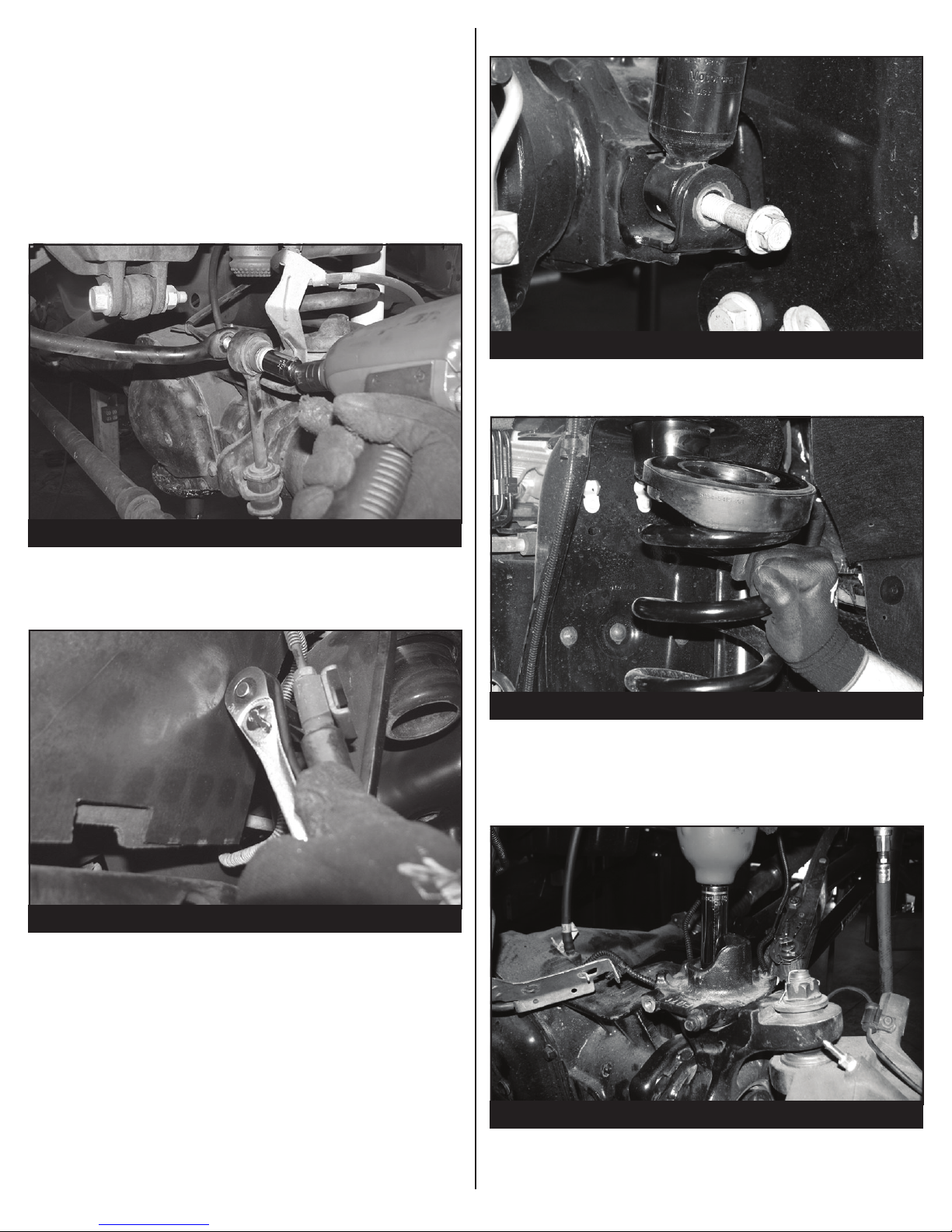
With the front axle supported, Disconnect the sway bar
2.
fr
om the endlink. Save hardware. SEE FIGURE 1
ont tires.
4. Remove and save lower shock hardware. SEE FIGURE 3
FIGURE 3 - STEP 4
5. Carefully lower the front axle and remove the factory coil
spring. SEE FIGURE 4
FIGURE 1 - STEP 2
Remove the brake line bracket fr
3.
models) SEE FIGURE 2.
FIGURE 2 - STEP 3
om the frame. (05-10
FIGURE 4 - STEP 5
6. Remove the factory lower spring perch from the axle and
discard the factory hardware. Install FT30162 (2” spacer)
using the M14 bolt and washer. SEE FIGURE 5-6
FIGURE 5 - STEP 6
Page 4
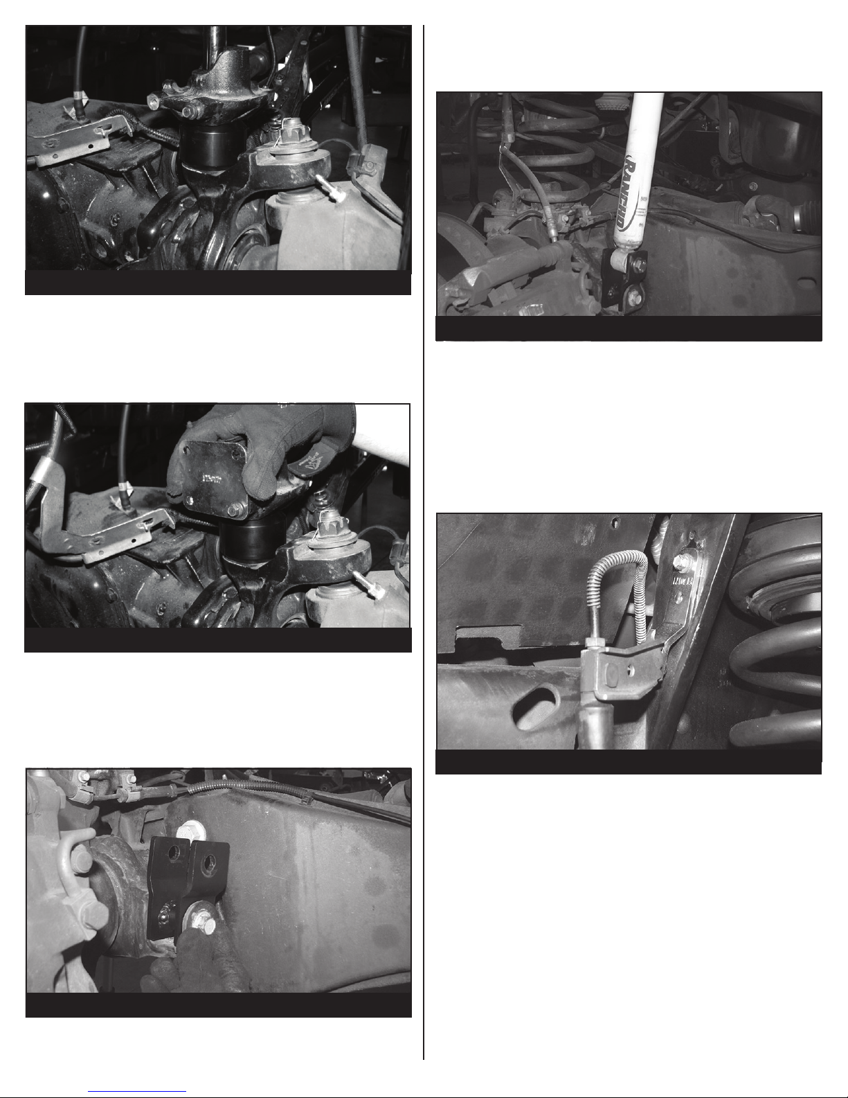
FIGURE 6 - STEP 6
7. Locate FT30172 (Brake line bracket), attach the bracket
to the factory spring perch using the supplied 8mm
hardware. Using the 5/16 hardware attach the factory
brake line bracket to the new Fabtech bracket. SEE
FIGURE 7
10. Locate the supplied M14-2.0x80mm HEX bolts, washers
and nuts. Re-install the factory shock using the supplied
M14 hardware. Torque the lower shock bolt to 160 ft-lbs.
And the upper shock mount 58 ft-lbs. SEE FIGURE 9
FIGURE 9 - STEP 10
FOR 2011-UP MODEL TRUCKS, SKIP TO STEP 12
11. Locate the factory brake line mount hole on the front side
of the coil bucket, attach FT30171 (brake line bracket) to
the hole using the original factory hardware. Attach the
factory brake line to the new bracket using the supplied
5/16” hardware. SEE FIGURE 10
FIGURE 7 - STEP 7
8. Re-install the factory coil spring.
9. Locate the FT30580 (driver shock extension), using the
factory lower shock hardware, install the shock extension
into the factory lower shock mount. Torque to 160 ft-lbs.
SEE FIGURE 8
FIGURE 8 - STEP 9
FIGURE 10 - STEP 11
12. Reconnect the sway bar using the factory hardware.
13. Install tires and wheels and torque lug nuts to wheel
manufacturer’s specications. Turn front tires left to right
and check for appropriate tire clearance. Note - Some
oversized tires may require trimming of the front
bumper & valance.
14. Check front end alignment and set to factory
specications. Readjust headlights.
Page 5

15. Recheck all bolts for proper torque.
16. Recheck brake hoses, ABS wires and suspension parts
for proper tire clearance while turning tires fully left to
right.
17. Check the uid in the front and rear differential and ll
if needed with factory specication differential oil. Note
- some differentials may expel fluid after filling and
driving. This can be normal in resetting the fluid level
with the new position of the differential/s.
18. Install Driver Warning Decal. Complete product
registration card and mail to Fabtech in order to receive
future safety and technical bulletins on this suspension.
Vehicles that will receive oversized tires should check ball
joints, uniballs and all steering components every
2500-5000 miles for wear and replace as required.
RE-TORQUE ALL NUTS, BOLTS AND LUGS
AFTER 50 MILES AND THEREAFTER UNTIL
FASTENERS RETAIN TORQUE SETTING.
 Loading...