

Fabtech FTS22179, FTS22181, FT22179i, FTS22177, FT22176i Installation Instructions Manual
...Page 1
INSTALLATION INSTRUCTIONS
2015-18 FORD F150 4WD
FTS22179 - 6” BASIC SYSTEM
FTS22181 - 6” PERFORMANCE SYSTEM
Fabtech Motorsports | 4331 Eucalyptus Ave. Chino, CA 91710
Tech Line: 909-597-7800 | Fax: 909-597-7185 | Web: www.fabtechmotorsports.com
FT22179i
Page 2
- PARTS LIST -
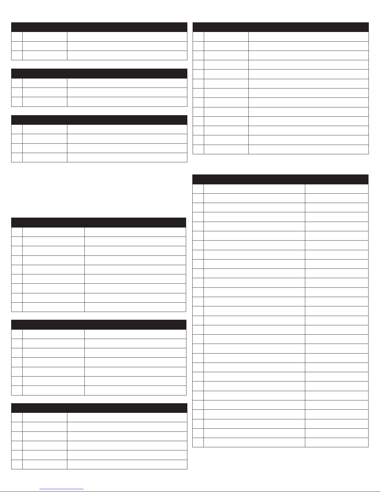
K2194 6” BASIC W/ REAR PERFORMANCE SHOCKS
1 FTS22179 COMPONENT BOX 1
1 FTS22180 COMPONENT BOX 2
2 FTS7266 REAR PERFORMANCE SHOCKS
K2194M 6” BASIC W/ REAR STEALTH SHOCKS
1 FTS22179 COMPONENT BOX 1
1 FTS22180 COMPONENT BOX 2
2 FTS6266 REAR STEALTH SHOCKS
K2195DB 6” PERFORMANCE W/ DIRT LOGIC SHOCKS
1 FTS22179 COMPONENT BOX 1
1 FTS22180 COMPONENT BOX 2
1 FTS221841 2.5” DIRT LOGIC COILOVERS (PAIR)
2 FTS810291 2.25” DIRT LOGIC NON RESI
FTS22179 COMPONENT BOX 1 - BASIC SYSTEM
1 FT30558BK COIL SPACER (DRIVER)
1 FT30605BK COIL SPACER (PASSENGER)
1 FT30377BK SKID PLATE
2 FT30378 DIFF DROP BRACKET UPPER
1 FT30645 DIFF MOUNT CENTER
1 FT30602 HARDWARE SUBASSEMBLY
1 FT30603 HARDWARE KIT
1 FT30601D or FT30600D SPINDLE (DRIVER)
1 FT30601P or FT30600P SPINDLE (PASSENGER)
FTS22181 COMPONENT BOX 1 - PERF SYSTEM
1 FT30377BK SKID PLATE
2 FT30378 DIFF DROP BRACKET UPPER
1 FT30645 DIFF MOUNT CENTER
1 FT30602 HARDWARE SUBASSEMBLY
1 FT30603 HARDWARE KIT
1 FT30601D or FT30600D SPINDLE (DRIVER)
1 FT30601P or FT30600P SPINDLE (PASSENGER)
FTS22180 COMPONENT BOX 2
1 FT30591 SWAY BAR DROP (DRIVER)
1 FT30590 SWAY BAR DROP (PASSENGER)
1 FT30644BK FRONT CROSSMEMBER
1 FT30673BK REAR CROSSMEMBER
4 FT737U UBOLT
2 FTBK52 LIFT BLOCK W/ BUMPSTOP
FT30602 HARDWARE SUB-ASSEMBLY
2 FT20277 OUTER TIE ROD
1 FT22179I INSTRUCTIONS
2 FT292 ALIGNMENT CAM KIT
2 FT70032 FRONT BRAKE LINE BRACKET
1 FT70033 REAR BRAKE LINE BRACKET
4 FT30604 LOWER BAR PIN SPACER
1 FT30646BK REAR DIFF PLATE
2 FT1020 BUSHING
1 FT181 SLEEVE .625 X .500 X 2.375
1 FT30608 DRIVE SHAFT SPACER
1 FT30610 5/16” X 6” RUBBER HOSE
1 FTAS16 DRIVER WARNING DECAL
1 FTREGCARD REGISTRATION CARD
FT30603 - HARDWARE KIT LOCATION
6 5/16 SAE WASHER G5 ZINC BRAKE LINE
3 5/16-18 STOVER NUT G5 Z1
3 5/16-18 X 1 HEX BOLT G8 ZINC
8 7/16 SAE WASHER G5 ZINC SWAY BAR EXT
4 7/16-14 C-LOCK NUT ZINC
4 7/16-14 X 1-1/4 HEX BOLT G8 ZNC
1 1/2-13 X 1-3/4 HEX BOLT G8 ZINC CENTER DIFF
16 1/2 SAE WASHER G5 ZINC DIFF MOUNT/ SKID
8 1/2-13 C-LOCK NUT ZINC
3 1/2-13 X 1-1/4 HEX BOLT G8 ZNC SKID PLATE
4 1/2-13 X 4” HEX BOLT G8 ZNC DIFF MOUNT
6 7/16-14 C-LOCK NUT ZINC SHOCK EXT
6 7/16 SAE WASHER G5 ZINC
4 1/2-13 X 3-1/2 HEX BOLT G8 ZNC LOWER SHOCK
8 1/2 SAE WASHER G8 ZINC
4 1/2-13 C-LOCK NUT ZINC
3 M10-1.5 X 45MM HEX BOLT CENTER DIFF
3 10MM SPLIT WASHER
3 M10 FLAT WASHER ZINC
8 9/16” SAE WASHER UBOLTS
8 9/16-18 NYLOCK NUT
2 THREAD LOCKING COMPOUND 1 MIL
1 M18-2.5 X 150MM HEX BOLT
1 M18-2.5 C-LOCK NUT
2 M18 SAE WASHER
4 3/8” SAE WASHER
2 3/8-16 X 1” HEX BOLT
2 3/8-16 C-LOCK
2 of 16
Page 3

Prior to installing this kit, with the vehicle on level
ground. Measure the height of your vehicle. This
measurement can be recorded from the center
of the wheel, straight up to the top of the inner
fender lip. Record the measurements below.
LF:______________________
RF:_______________________
LR:______________________
RR:_______________________
- TOOL LIST -
Required Tools (Not Included)
Floor Jack Jack Stands Torque Wrench
Assorted Metric and S.A.E sockets, and Allen wrenches
Die Grinder w/Cut-off Wheel Torque Wrench
1-1/2” Barrel Sand Wheel 1/2” Barrel Sand Wheel
- PRE-INSTALLATION NOTES -
For technical assistance call: 909-597-7800 or e-mail: [email protected]
Read this before you begin installation-
Check all parts to the parts list above before beginning installation. If any parts are missing contact Fabtech at 909-597-7800
and a replacement part will be sent to you immediately.
Read all instructions thoroughly from start to finish before beginning the installation. If these instructions are not properly
followed severe frame, driveline and / or suspension damage may occur.
Check your local city and state laws prior to the installation of this system for legality. Do not install if not legal in your area.
Prior to the installation of this suspension system perform a front end alignment and record. Do not install this system if the
vehicle alignment is not within factory specifications. Check for frame and suspension damage prior to installation.
The installation of this suspension system should be performed by two professional mechanics.
Use the provided thread locking compound on all hardware.
Do not combine this suspension system with any other lift device or parts.
This suspension must be installed with Fabtech shock absorbers.
WARNING- Installation of this system will alter the center of gravity of the vehicle and may increase roll over as compared
to stock.
On EcoBoost 3.5L and 2.7L models, discard all air shields.
OEM Wheels and tires cannot be used after the installation of this kit. Larger tires cannot be installed on the OEM wheels.
Verify differential fluid is at manufacture’s recommended level prior to kit installation. Installation of the kit will reposition the
differential and the fill plug hole may be in a different position. (For example, if the manufacture recommends 3 quarts of fluid,
make sure the diff has 3 quarts of fluid). Check your specific manual for correct amount of fluid.
Recommend Tires and Wheels:
Use 35/13.50R18 tires w/ 18x9 wheels w/ 5” BS w/ minor trimming
Use 35/13.50R20 tires w/ 20x9 wheels w/ 5” BS w/ minor trimming
Use 285/55R22 tires w/ 22x9.5 wheels w/ 5” BS w/ minor trimming
3 of 16
Page 4
- INSTRUCTIONS -
FRONT SUSPENSION
1. Disconnect the negative terminal on the battery. Jack
up the front end of the truck and support the frame
rails with jack stands. NEVER WORK UNDER AN
UNSUPPORTED VEHICLE! Remove the front tires.
2. Remove and discard the factory splash guard under the
differential.
3. Locate the sway bar end links and disconnect from the
factory lower control arms, save the hardware. Locate
the sway bar frame mounts and disconnect them from
the frame. Remove the sway bar from the truck. Save the
hardware and sway bar.
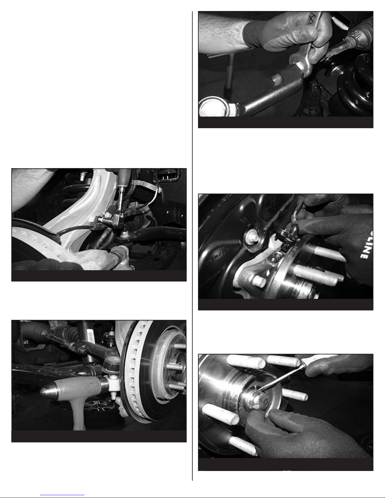
4. Working from the driver side of the vehicle disconnect
the brake line and ABS line from the factory knuckle. SEE
FIGURE 1
FIGURE 3 - STEP 6
7. Remove the brake caliper and place it next to the frame.
Do not overstretch the brake hose when doing so. Retain
the hardware for reinstallation. Remove the brake rotor
and save. Disconnect the vacuum lines attached to the
rear of the hub assembly. Allow the vacuum lines to hang
freely. Remove the electronic stability control (ESC) sensor
from the top of the hub. Cover the sensor to keep it free
from dirt and debris. SEE FIGURE 4
FIGURE 1 - STEP 4
5. Disconnect the tie rod ends from the steering knuckle
by striking the knuckle to dislodge the tie rod end. SEE
FIGURE 2
FIGURE 2 - STEP 5
6. Remove factory Tie Rod end and discard. SEE FIGURE 3
FIGURE 4 - STEP 7
8. Carefully remove the dust cap covering the hub assembly
nut. Remove the C.V. bearing nut and save the nut and
dust cap. Remove the dust shield and save for reinstallation. SEE FIGURE 5
FIGURE 5 - STEP 8
4 of 16
Page 5
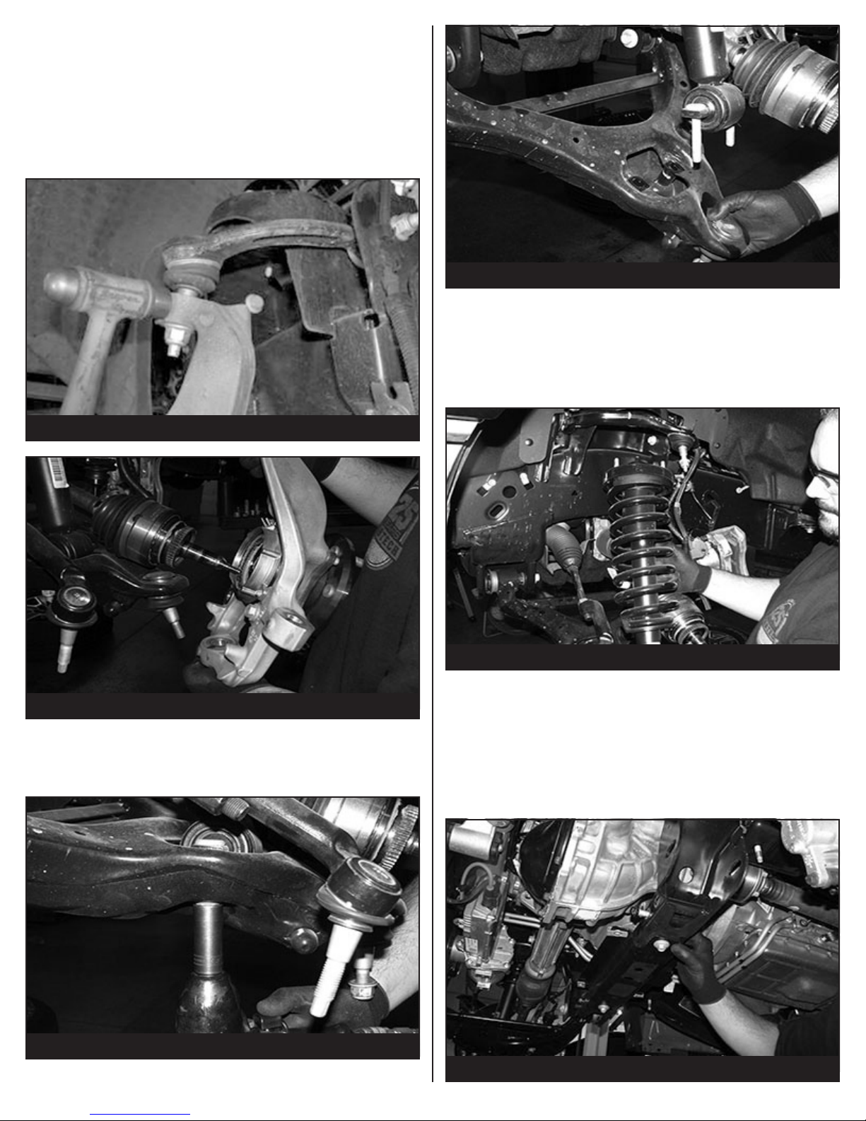
9. Remove the upper and lower ball joint nuts. Disconnect
the upper and lower ball joints from the steering knuckle
by striking the knuckle with a large hammer next to each
ball joint on the knuckle to dislodge the ball joints. Use
care not to hit the ball joints when removing. Retain
hardware and remove the knuckle with the hub. Use extra
care not to over extend the C.V. axle shaft when removing
the knuckle. SEE FIGURES 6-7
FIGURE 6 - STEP 9
FIGURE 9 - STEP 10
11. Locate the three upper coilover nuts and remove. Save
the hardware. Remove the shock assembly from the
vehicle and mark “Driver” for assembly to install later with
Fabtech shock extensions. NOTE: If installing Dirt Logic
coilovers the factory coilover and hardware will not be
re-used. SEE FIGURE 10
FIGURE 7 - STEP 9
10. Locate the lower shock mount bar pin nuts and remove.
Loosen and remove the control arm at the crossmembers
and save for re-installation. SEE FIGURES 8-9
FIGURE 8 - STEP 10
FIGURE 10 - STEP 11
12. Repeat steps 4 through 11 on the passenger side of the
truck.
13. Remove the factory rear crossmember from the vehicle
and discard. NOTE: Due to variances in vehicles, the
bolt attaching the crossmember and the frame on the
drivers side may need to be cut off. SEE FIGURE 11-12
FIGURE 11 - STEP 13
5 of 16
Page 6
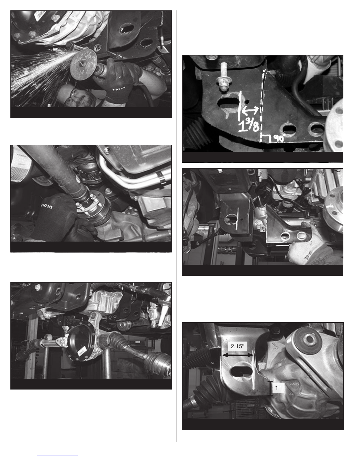
FIGURE 12 - STEP 13
2.15”
1”
14. Remove the front drive shaft bolts where they attach to
the front differential. Support the end of the driveshaft
before removing the front differential. SEE FIGURE 13
16. Locate the driver side rear lower control arm pocket. Mark
the frame 1-3/8’’ from the control arm pivot hole and 90
degrees to the bottom of the pocket where the cross
member was mounted. Using a die grinder, cut all the
way around the pocket. Discard removed portion of the
pocket. SEE FIGURES 15-16
FIGURE 15 - STEP 16
FIGURE 13 - STEP 14
15. Supporting the differential, remove the 3 differential mount
bolts and save for re-installation. Remove the differential
from the vehicle. SEE FIGURE 14
FIGURE 14 - STEP 15
FIGURE 16 - STEP 16
17. Still working on the driver side rear lower control arm
pocket, locate the tab on the pocket towards the rear of
the vehicle. You will need to cut and sand a radius in the
rear side of the pocket in order to clear the differential
housing. SEE FIGURE 17
FIGURE 17 - STEP 17
6 of 16
Page 7
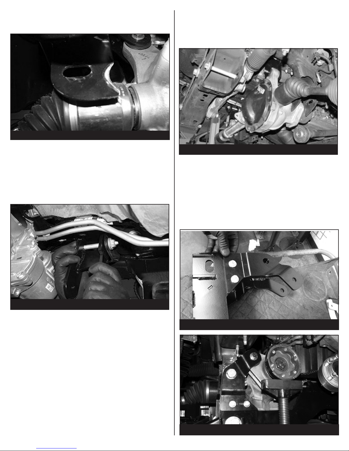
18. Locate the front tab on the same mount. You will need
to sand a 1/2” on the inside to clear the differential. SEE
FIGURE 18
FIGURE 18 - STEP 18
20. Locate the factory front differential and install into the
Fabtech upper differential mounts using two ½’’-13 x 4’’
hex cap bolts, washers and lock nuts. Leave all hardware
loose in preparation of the installation of the remaining
differential mounts. SEE FIGURE 20
19. Locate the two Fabtech upper differential mounts
(FT30378). These upper differential mounts will be placed
into the factory upper differential mounts using the factory
upper differential mount hardware. Leave the hardware
loose in preparation for the differential installation. Open
end towards the inside.
SEE FIGURES 19
FIGURE 19 - STEP 19
FIGURE 20 - STEP 20
21. Locate the Fabtech rear crossmember (FT30673BK)
and rear diff plate (FT30646BK). Install the rear diff plate
(FT30646BK) on the (FT30673BK) rear crossmember
using the 3/8” hardware. Leave loose. Next, mount the
crossmember using the 18mm hardware and 1/2-13 x
4” bolt and hardware. Leave all hardware loose. NOTE:
It may be necessary to jack up the rear of the diff to
install the 18mm and 1/2” hardware. SEE FIGURES
21-23
FIGURE 21 - STEP 21
FIGURE 22 - STEP 21
7 of 16
Page 8
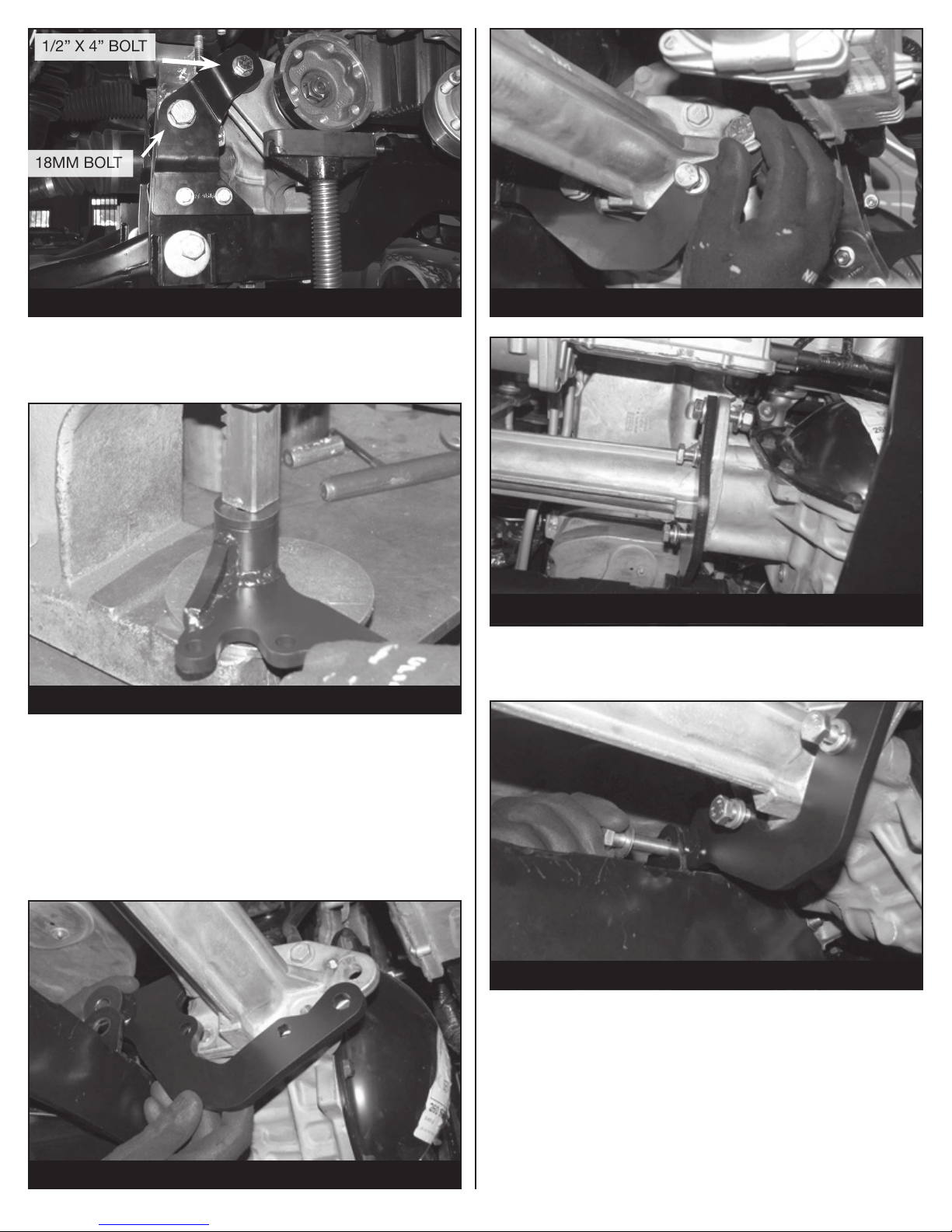
FIGURE 23 - STEP 21
18MM BOLT
1/2” X 4” BOLT
22. Locate the center differential bracket (FT30645). Install
two of the Fabtech (FT1020) bushings and one sleeve
(FT181) into the barrel on the differential bracket.
SEE FIGURE 24
FIGURE 24 - STEP 23
23. On the front axle tube, remove the rear and lower bolts
to allow for the new center differential bracket to be
mounted.
FIGURE 26 - STEP 24
FIGURE 27 - STEP 24
25. Install a ½” -13 x 4” bolt, washers and nut through the
tabs on the rear crossmember and the bushing on the
center bracket. Leave loose at this time. SEE FIGURE 28
24. Mount the differential bracket to the center of the
differential using three M10-1.5 x 45mm bolts, lock
washers, and at washers. Mount the front tab on the diff
to the center bracket using one ½”-13 x 2” bolt, nut and
washers. Leave loose at this time. SEE FIGURES 25-27
FIGURE 25 - STEP 24
FIGURE 28 - STEP 25
8 of 16
Page 9
26. Torque the M10-1.5 x 45mm bolts to 35 ft-lbs. Torque the
FT30608
½”-13 x 2” bolt to 90 ft-lbs.
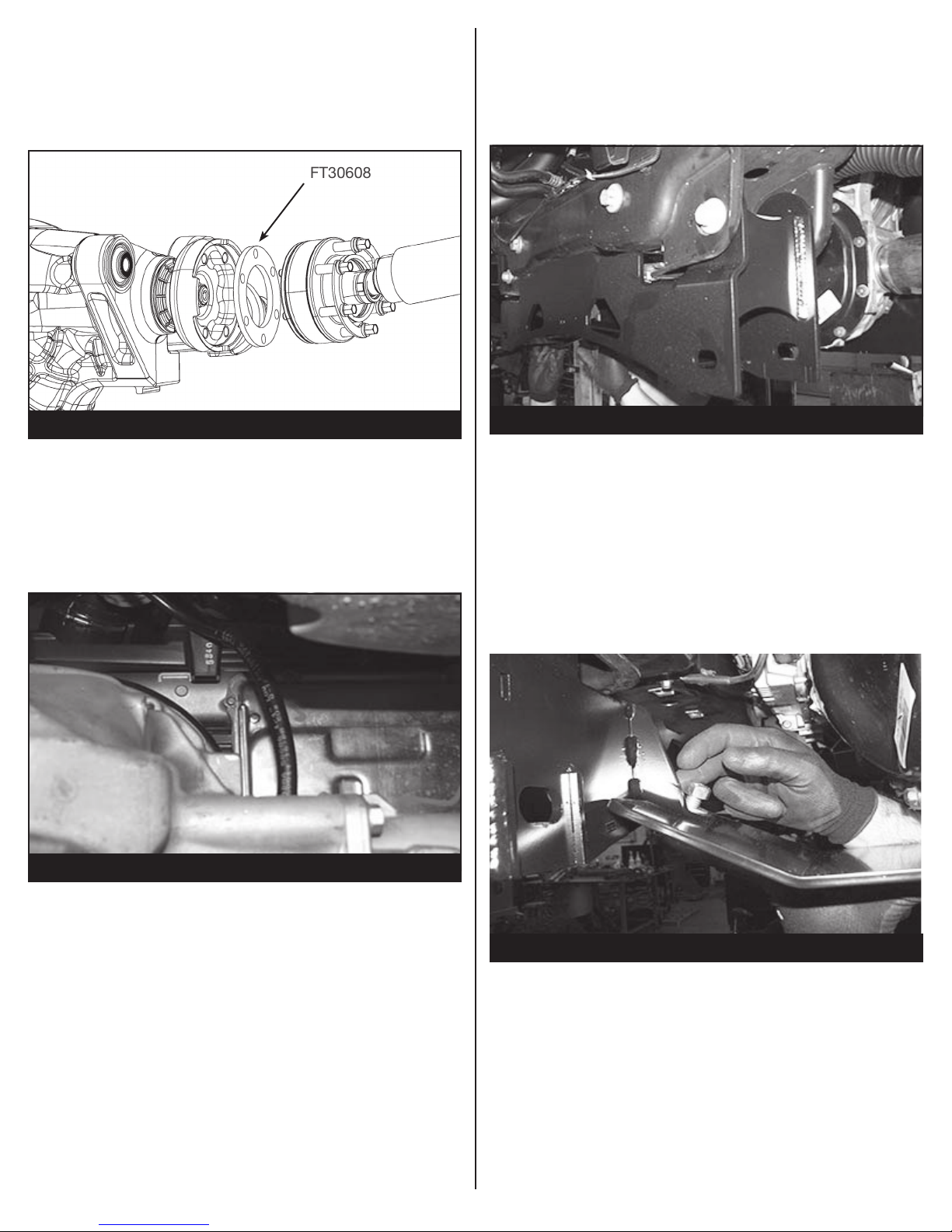
27. When reinstalling the front drive shaft. Install FT30608
(Driveshaft spacer) with the factory hardware and torque
to 35 ft-lbs. SEE FIGURE 29
30. Locate the Fabtech front crossmember (FT30644BK).
Install the front crossmember into the factory front control
arm pockets using the factory hardware. Make sure the
skid plate tab on the crossmember is facing the Fabtech
rear crossmember. Leave the hardware loose at this time.
SEE FIGURE 31
FIGURE 29 - STEP 27
28. Locate upper differential brackets and torque the factory
upper bolts to 90 ft-lbs and lower ½’’ bolts 127 ft-lbs.
Locate the center diff mount on the cross member and
torque the ½”-13 x 4” bolt to 90 ft-lbs.
29. Install the supplied 6” hose to the factory differential vent
tube and back on to the differential. SEE FIGURE 30
FIGURE 30 - STEP 29
FIGURE 31 - STEP 30
31. Locate the Fabtech skid plate (FT30377BK). The skid
plate will span the distance between the front and rear
crossmembers directly under the front differential. Attach
the end of the skid plate with the single hole to the tab on
the back side of the front crossmember using one ½’’- 13
x 1-1/4” bolt, washers and a C-lock nut. Leave loose at
this time. Lift up the back side of the skid plate and install
it to the rear crossmember using two ½’’- 13 x 1-1/4”
bolts, washers and a C-lock nut. Torque only the 2 rear
bolts at this time to 127 ft-lbs. SEE FIGURE 32
FIGURE 32 - STEP 31
9 of 16
Page 10
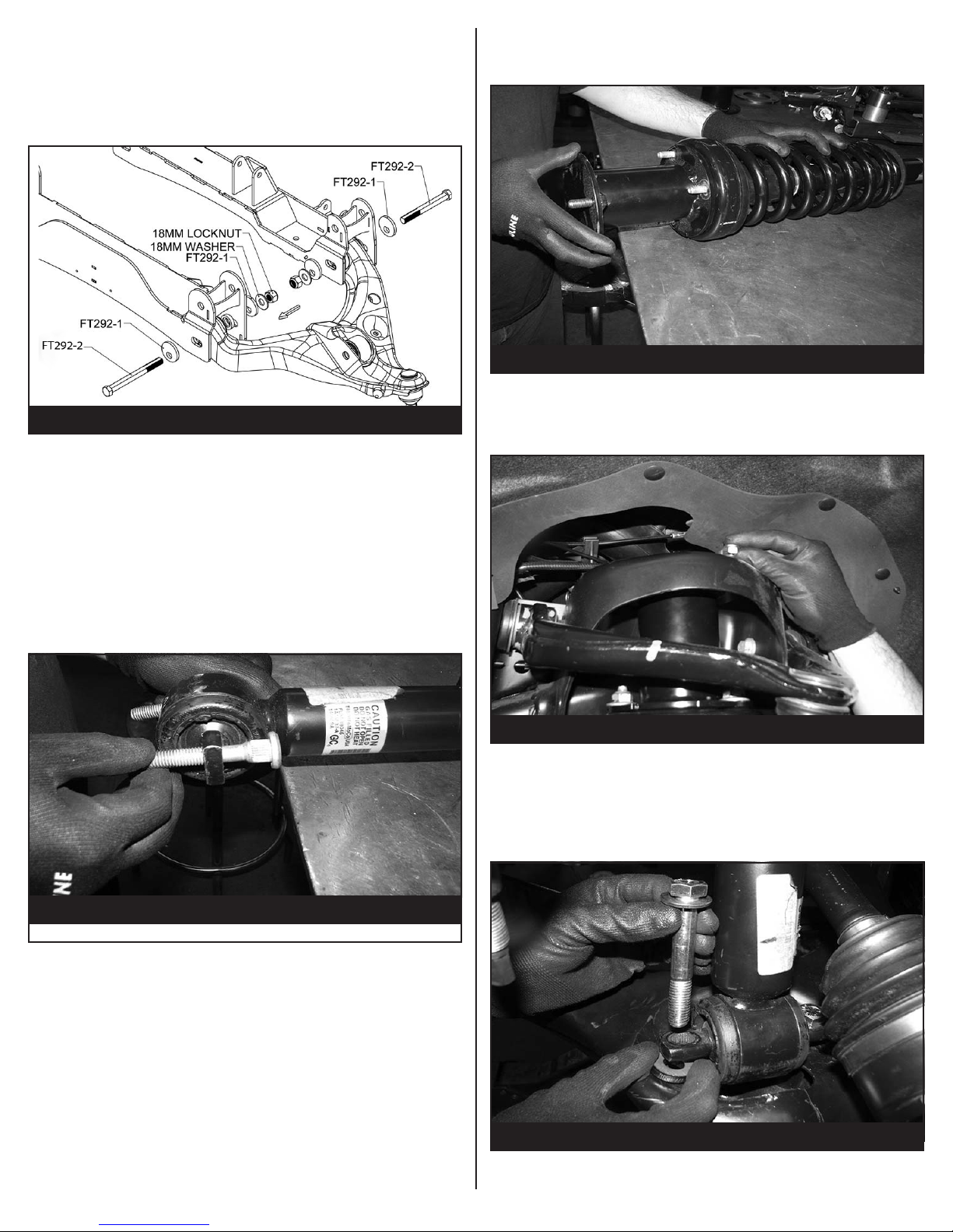
32. Locate the Alignment cam kit (FT292). Locate the
factory control arms. Install the lower control arms into
the Fabtech crossmembers using the hardware in the
cam kit (FT292). Torque the cam bolts at 200 ft-lbs after
alignment. Torque crossmember bolts to 240 ft-lbs. SEE
FIGURE 33
FIGURE 33 - STEP 32
33. If installing Dirt Logic coilovers (FTS221841) do so at
this time, using the instructions provided in the shock
box. Once finished, you may skip to STEP 39.
If using the factory coilover continue to STEP 34.
36. Install the Driver side spacer on the driver side coilover
using the factory hardware and torque to 35 ft-lbs. Repeat
on the passenger side. SEE FIGURE 38
FIGURE 35 - STEP 39
37. Install the coil over into the frame bucket using the
supplied 7/16” hardware. Torque 59 ft-lbs. SEE FIGURE
36
34. Locate the FT30558BK (Driver) and FT30605BK (Pass)
shock spacers.
35. Locate the factory coilovers. Using a press, press the
factory studs out of the bar pins. SEE FIGURE 34
FIGURE 34 - STEP 35
FIGURE 36 - STEP 42
38. Rotate the lower control arm up and mount to the lower
coilover bar pin using the supplied 1/2” hardware.
NOTE: Install the lower bar pin spacers under the bar pin
(FT30604). Torque to 127 ft-lbs. SEE FIGURE 37
FIGURE 37 - STEP 38
10 of 16
Page 11
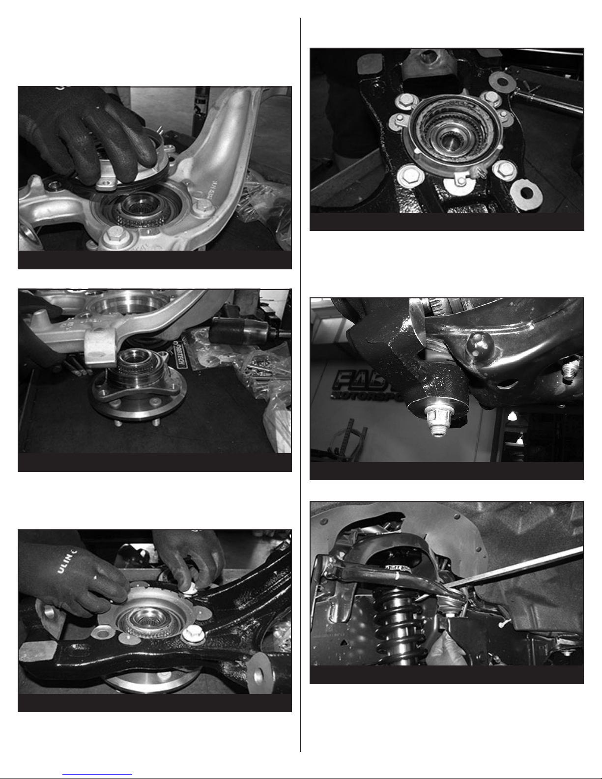
39. Locate the factory knuckle and remove the 4WD actuator
and hub assembly. SEE FIGURES 38-39 NOTE: REFER
TO FIGURE 65 ON THE LAST PAGE FOR SPECIFIC
INSTRUCTIONS ON DISASSEMBLY AND ASSEMBLY
OF THE 4WD ACTUATOR.
41. Re-install the 4WD actuator using the 3 factory bolts.
Torque to 29 ft-lbs. SEE FIGURE 41
FIGURE 41 - STEP 41
FIGURE 38 - STEP 39
FIGURE 39 - STEP 39
40. Locate the Fabtech driver side spindle (FT30601D) or
(FT30600D) and install the factory hub. Torque the four
14mm bolts to 160 ft- lbs. SEE FIGURE 40
42. Install the Fabtech knuckle onto the upper and lower
control arms. Torque the upper ball joint to 85 ft-lbs and
the lower ball joint to 110 ft-lbs. SEE FIGURE 42-43
FIGURE 42 - STEP 42
FIGURE 40 - STEP 40
FIGURE 43 - STEP 42
11 of 16
Page 12
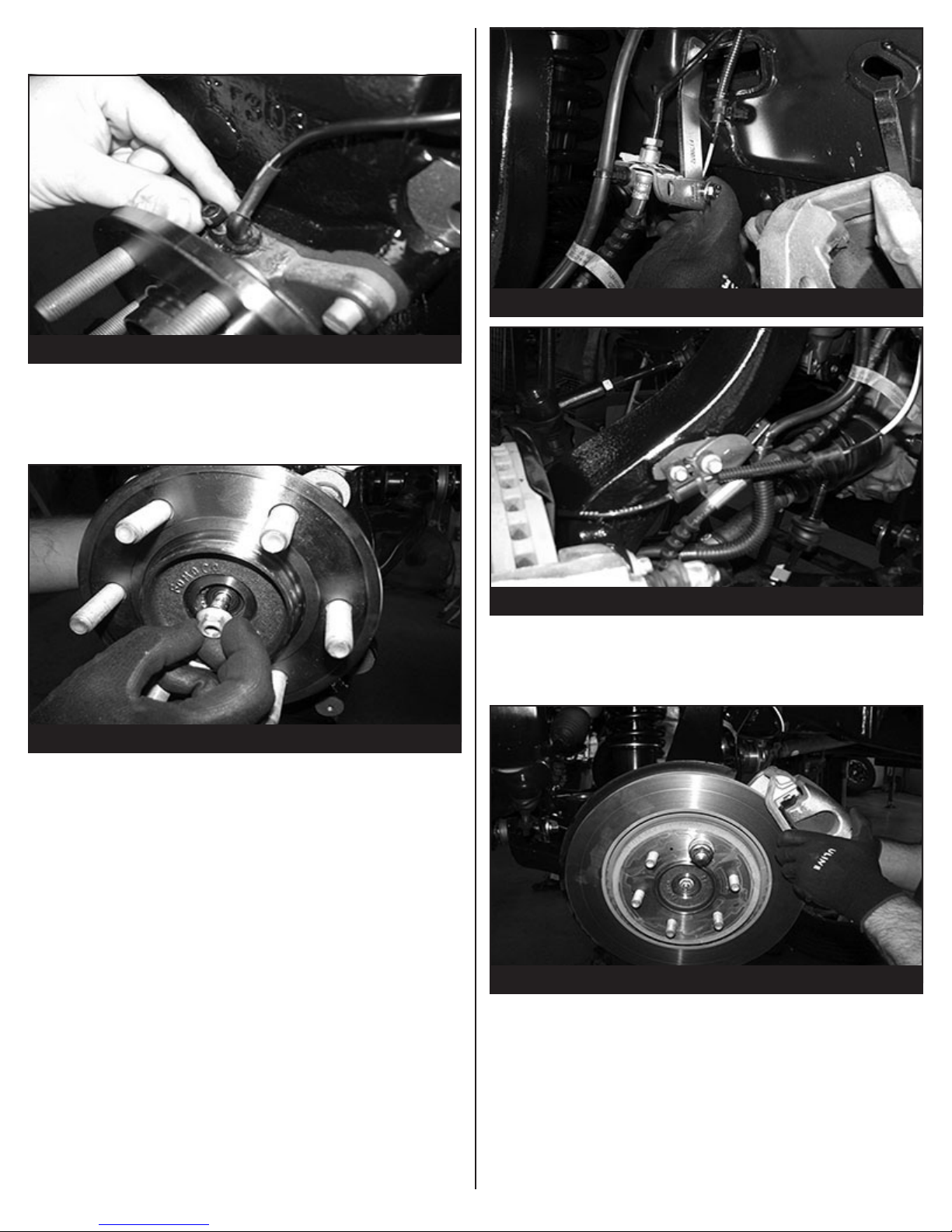
43. Install the wheel speed sensor. Make sure the end of the
sensor is clean. Torque to 21 ft-lbs SEE FIGURE 44
FIGURE 44 - STEP 43
44. Install the dust shield and torque to 14 ft-lbs. Install CV
shaft nut and torque to 35 ft-lbs. Install the factory dust
cover. SEE FIGURE 45
FIGURE 46 - STEP 45
FIGURE 45 - STEP 44
45. Reconnect the vacuum line to the hub assembly. Using
the factory bolt Install the Fabtech brake line bracket
(FT70032) to the frame. Use the supplied 5/16” hardware
to connect the brake line to the new Fabtech bracket.
Using the factory hardware, mount factory brake
line bracket to the side of the Fabtech knuckle. After
installing the factory brake line bracket, check to insure
full movement by steering the knuckle back and forth,
and make sure none of the ABS lines, brake lines, or
vacuum lines are inhibited during full test movement of the
knuckle. SEE FIGURES 46-47
FIGURE 47 - STEP 45
46. Reinstall the original brake rotor, followed by the brake
caliper. Use a small amount of the supplied thread lock
compound on the caliper bolts and torque to 145 ft-lbs.
SEE FIGURE 48
FIGURE 48 - STEP 46
12 of 16
Page 13
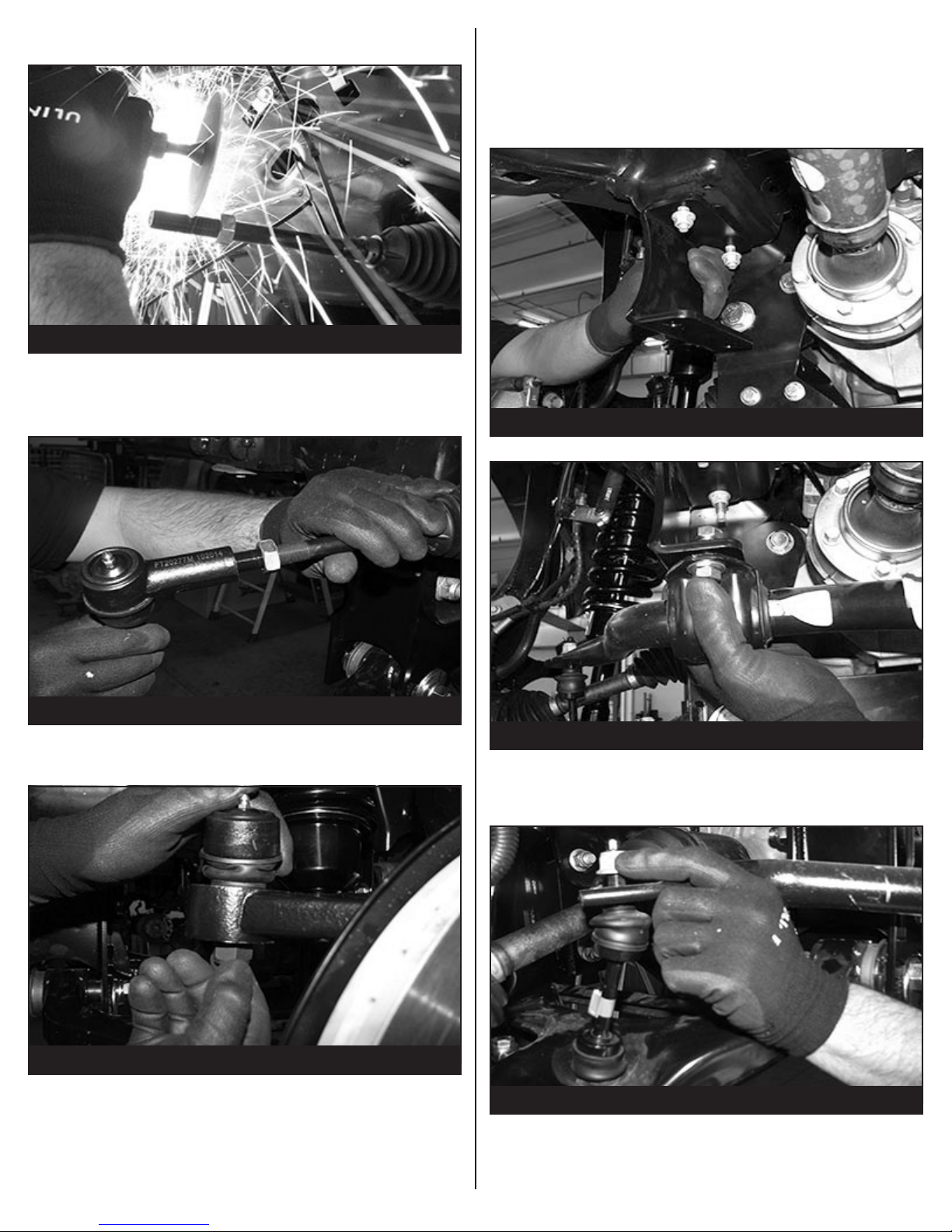
47. Locate the factory tie rod. Trim 1’’ off the end.
SEE FIGURES 49
FIGURE 49 - STEP 47
48. Locate the Fabtech tie rod end (FT20277). Install the tie
rod end on the tie rod. SEE FIGURE 50
50. Using the supplied 7/16” hardware install the factory
sway bar to the frame using the FT30591 (driver side
bracket) and the FT30590 (passenger side bracket). When
mounting, the sway bar will be offset towards the rear
of the truck and the at side towards the outside. SEE
FIGURES 52-53
FIGURE 52 - STEP 50
FIGURE 50 - STEP 50
49. Reconnect the tie rod end to the steering knuckle and
torque to 60 ft-lbs. SEE FIGURE 51
FIGURE 51 - STEP 49
FIGURE 53 - STEP 50
51. Install the sway bar end to the factory lower control arm
using the factory end links. SEE FIGURE 54
FIGURE 54 - STEP 51
13 of 16
Page 14
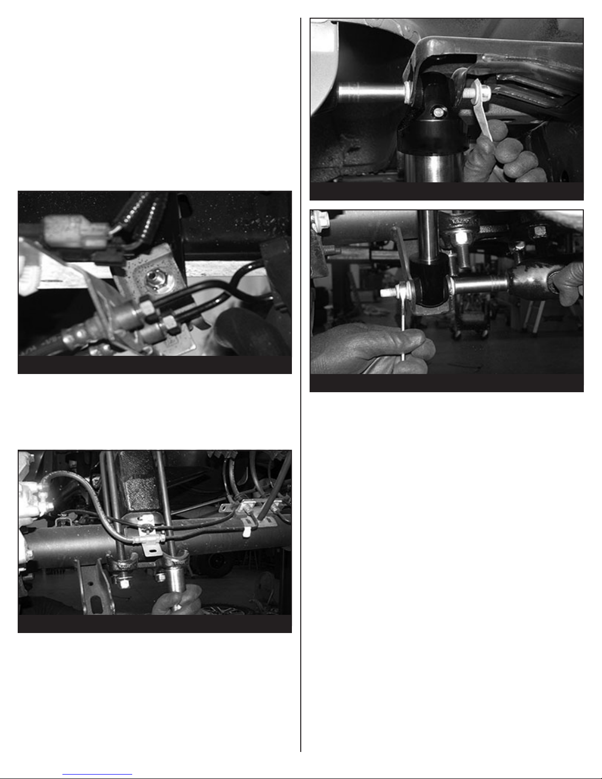
REAR SUSPENSION
52. Jack up the rear end of the vehicle and support the frame
rails with jack stands. Release the parking brake at this
time. Supporting the rear differential, remove the rear
shocks, u-bolts, blocks and lower axle down. Use care
not to over extend the brake hose.
53. Locate the factory brake line mount on the driver side
of the frame. Locate the supplied brake line bracket
(FT70033) and attach the bracket between the factory
fame mount and the factory brake line using the factory
and supplied 5/16” hardware using the inside holes. SEE
FIGURE 55
FIGURE 57 - STEP 55
FIGURE 55 - STEP 53
54. Locate and install the rear lift blocks FTBK52. The
extended bump stop perch will be facing inboard of the
truck. Using the provided u-bolts, nuts and washers, align
the axle, lift blocks, and springs and torque u-bolts to 90
ft-lbs. SEE FIGURE 56
FIGURE 56 - STEP 54
55. Locate the Fabtech performance shocks (FTS7266),
Stealth shocks(FTS6266) or Dirt Logic shocks
(FTS810291). Install the shocks using the factory
hardware and torque upper and lower bolts to 45 ft-lbs.
SEE FIGURES 57-58. NOTE: The FTS7266 and FTS6266
shocks are to be installed with the body down.
FIGURE 58 - STEP 55
56. Install tires and wheels and torque lug nuts to wheel
manufacturer’s specications. Turn front tires left to right
and check for appropriate tire clearance. Note - Some
oversized tires may require trimming of the front
bumper & valance.
57. Check front end alignment and set to factory
specications. Readjust headlights.
58. Recheck all bolts for proper torque.
59. Check the uid in the front and rear differential and ll
if needed with factory specication differential oil. Note
- some differentials may expel fluid after filling and
driving. This can be normal in resetting the fluid level
with the new position of the differential/s.
60. Install Driver Warning Decal. Complete product
registration card and mail to Fabtech in order to receive
future safety and technical bulletins on this suspension.
Vehicles that will receive oversized tires should check ball
joints and all steering components every 2500-5000 miles
for wear and replace as required.
RE-TORQUE ALL NUTS, BOLTS AND LUGS
AFTER 50 MILES AND THEREAFTER UNTIL
FASTENERS RETAIN TORQUE SETTING.
For technical assistance call: 909-597-7800
14 of 16
Page 15
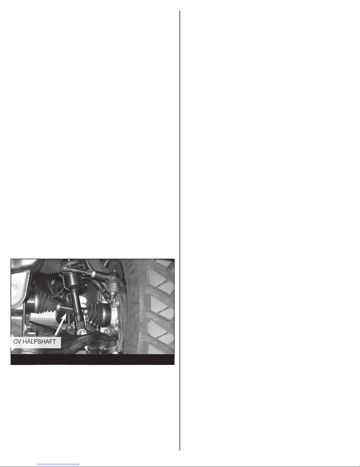
Procedure for checking proper
CV HALFSHAFT
installation of HUB actuator.
• The IWE system uses vacuum hubs that engage the front
wheel hubs to the front halfshafts or disengage the front
wheel hubs from the front halfshafts.
• The IWE solenoid receives engine vacuum from the
vacuum reservoir.
• When the 4-wheel drive system is in 2WD mode, the 4x4
module (PCM) supplies a ground path to the IWE solenoid
to apply vacuum to the wheel ends (disengaging the front
hubs from the front halfshafts). In 4WD mode, the 4x4
module (PCM) does not supply the ground path to the
IWE solenoid, vacuum is not applied to the integrated
wheel ends and an internal spring keeps the front hubs
engaged to the front halfshafts.
- FIGURE 65 -
NOTE: Specific IWE “Integrated Wheel End” installation
procedures are necessary when servicing and/or IWE
vacuum is released. When the IWE actuator is loosened at
the knuckle and/or removed from CV shaft:
• Remove the two vacuum line, compress the IWE actuator
and install a vacuum cap on the larger vacuum port (to
keep it compressed).
• Install the IWE actuator onto the halfshaft outer end (if
removed).
• Do not dislodge the IWE seal spring when installing
an IWE on a CV halfshaft outboard end or component
damage may occur.
• Allow the wheel knuckle to swing outward while keeping
the halfshaft pushed inward.
• Once clearance is available, install the halfshaft outboard
end into the wheel knuckle hub bearing.
1. With the vehicle on level ground. Engage the emergency
brake and chalk the rear wheels.
2. Jack up the front driver side enough so the wheel/tire
spins freely.
3. With the vehicle in PARK, start the engine. NOTE: MAKE
SURE THE VEHICLE IS PLACED IN 2WD. Rotate the
wheel/tire and check to see if the CV halfshaft rotates. If
the CV halfshaft rotates, either a vacuum leak is present or
the IWE (Intergrated Wheel End) was installed improperly.
NOTE: DO NOT OPERATE THE VEHICLE OR DAMAGE
WILL OCCUR. SEE FIGURE 56
• Connect the upper ball joint and install new nut; torque to
85 ft-lbs.
• Install the three IWE actuator to wheel knuckle retaining
bolts; torque to 106 ft-lbs
• Remove the IWE vacuum cap and reconnect the vacuum
tubes.
• Verify the spline engagement by checking for spline lash
before installing the axle nut or component damage may
occur.
• Install new axle nut; 30 ft-lbs
4. If the CV halfshaft remains stationary when the wheel/tire
is rotated repeat steps 1-3 on the front passenger wheel/
tire.
Page 16

- Product Warranty and Warnings -
Fabtech provides a Limited Lifetime Warranty to the original retail purchaser who owns the vehicle, on which the product was
originally installed, for defects in workmanship and materials.
The Limited Lifetime Warranty excludes the following Fabtech items; bushings, bump stops, ball joints, tie rod ends, limiting
straps, cross shafts, heim joints and driveshafts. These parts are subject to wear and are not considered defective when worn.
They are warranted for 60 days from the date of purchase for defects in workmanship.
Dirt Logic and Performance Coilover take apart shocks are considered a serviceable shock with a one year warranty on leakage
only. Service seal kits are available separately for future maintenance. All other shocks are covered under our Limited Lifetime
Warranty.
Fabtech does not warrant any product for finish, alterations, modifications and/or installation contrary to Fabtech’s instructions.
Alterations to the finish of the parts including but not limited to painting, powder coating, plating and/or welding will void all
warranties. Some finish damage may occur to parts during shipping, which is considered normal and is not covered under
warranty.
Fabtech products are not designed nor intended to be installed on vehicles used in race applications or for racing purposes or
for similar activities. (A “RACE” is defined as any contest between two or more vehicles, or any contest of one or more vehicle
against the clock, whether or not such contest is for a prize). This warranty does not include coverage for police or taxi vehicles,
race vehicles, or vehicles used for government or commercial purposes. Also excluded from this warranty are sales outside of
the United States of America.
Installation of most suspension products will raise the center of gravity of the vehicle and will cause the vehicle to handle
differently than stock. It may increase the vehicle’s susceptibility to a rollover, on road and off road, at all speeds. Extreme care
should be taken to operate the vehicle safely at all times to prevent rollover or loss of control resulting in serious injury or death.
Fabtech front end Desert Guards may impair the deployment or operation of vehicles equipped with supplemental restraining
systems/air bag systems and should not be installed if the vehicle is equipped as so.
Fabtech makes every effort to ensure suspension product compatibility with all vehicles listed on the website, but due
to unknown auto manufacturer’s production changes and/or inconstancies by the auto manufacturer, Fabtech cannot be
responsible for 100% compatibility, including the fitment of tire and wheel sizes listed. The Tire and Wheel sizes listed in
Fabtech’s website are only a guideline for street driving with noted fender trimming. Fabtech is not responsible for damages
to the vehicle’s body or tires. Fabtech is not responsible for premature wear of factory components due to the installation of
oversized tires and wheels.
Fabtech’s obligation under this warranty is limited to the repair or replacement, at Fabtech option, of the defective product only.
All costs of removal, installation or re-installation, freight charges, incidental or consequential damages are expressly excluded
from this warranty. Fabtech is not responsible for damages and/or warranty of other vehicle parts related or non related to the
installed Fabtech product. This warranty is expressly in lieu of all other warranties expressed or implied. This warranty shall not
apply to any product that has been subject to accident, negligence, alteration, abuse or misuse as determined by Fabtech.
Fabtech suspension components must be installed as a complete system including shocks as shown on our website. All
warranties will become void if Fabtech parts are combined and/or substituted with other aftermarket suspension products.
Combination and/or substitution of other aftermarket suspension parts may cause premature wear and/or product failure
resulting in an accident causing injury or death. Fabtech does not warrant products not manufactured by Fabtech.
Depending on the condition of the factory suspension components retained after the installation of a Fabtech suspension not
all vehicles may have the same ride stance front to rear as described in the website. The blue color of suspension components
shown in all Fabtech photographs are for display purposes only. Majority of all Fabtech components will be black specifically
where noted with part numbers ending in BK.
Installation of Fabtech product may void the vehicles factory warranty; it is the consumer’s responsibility to check with their
local vehicle’s dealer for warranty disposition before the installation of the product. Some state laws may prohibit modification of
suspension to a vehicle in whole or in part. It is the responsibility of the installer and consumer to consult local laws prior to the
installation of any Fabtech suspension product to comply with such written laws.
It is the responsibility of the distributor and/or the retailer to review all warranties and warnings of Fabtech products with the
consumer prior to purchase.
Fabtech reserves the right to super cede, discontinue, change the design, finish, part number and/or application of parts when
deemed necessary without written notice. Fabtech is not responsible for misprints or typographical errors within the website or
price sheet. For the most recent Product Warranty and Warnings visit our website www.fabtechmotorsports.com
Instruction Sheet Part# - FT22179i-2 REV. AK 08/20/18
16 of 16
 Loading...