

Page 1
Version 1.0 FX5406 Series User’s Quick Reference Page 1/2
1. Brief
The FX5406x is a compact size embedded system with Intel® Atom™ D425 processor board inside.
This user’s quick reference provides the I/O outlets description and their pin assignment.
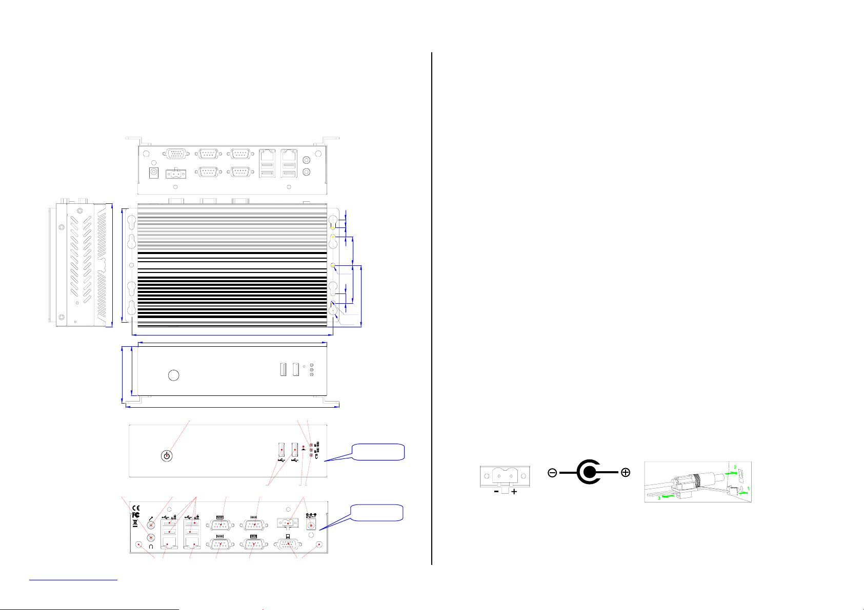
2. Dimensions (in mm) and Front/Real Panel Information
8
0
1
0
0
0
3
2
1
1
213(REF)
200
)
F
E
2
5
R
(
5
.
0
6
226(REF)
POWER BUTTON LAN2 LAN1
1
2
3
O4.5
0
)
4
F
E
0
R
(
1
5
6
R2.5
R4.5
Front Panel
3. Packing List
A. Standard Items
1 FX5406x embedded system.
1 AC to DC power adapter and 1 AC power cord cable.
1 pack of 2.5” SATA hard disk installation kit (2 cables with 4 fixed screws).
1 pack of wall mounting kit (2 pieces of metal with 4 fixed screws)
1 2-pin apartable terminal block.
1 compact disc includes software utilities and manuals.
B. Optional Items
z Half size mini PCIe module adapter kit (AK1006, 1 piece of metal with 2 screws, P/N:
0606010028G)
z Rack mounting kit (FX5403K1, 2 pieces of metal with 4 screws, P/N: 0606010011G)
z Panel back mounting kit (FX5504K1, 1 stand with 2 screws, P/N: 0606010012G)
4. Features
* Processor Board
Intel® Atom™ D425 (1.8GHz, 512KB L2, FSB 800MHz, 10 Watts) low power processor with 1GB
(2GB maximum) DDR3 RAM.
* I/O Outlets
Two 10/100/1000 base-TX Ethernet ports.
6 USB ports, 2 RS-232, and 2 RS-232/422/485 serial ports.
1 VGA, 1 Earphone and 1 Microphone connectors.
1 DC-In plug connector, 1 terminal block, and 1 power switch with power LED indicator.
1 HDD/CF access LED and 2 LAN LEDs.
* Storage Bay
1 CompactFlash socket for CompactFlash modules or MicroDrives.
1 SATA DOM space.
One 2.5" SATA hard disk space.
* Power requirement
+12 ~ +24V DC, 2.17A maximum (1.35A typical) with 19V input voltage.
* Dimensions
130.0mm(D) x 200.0mm(W) x 52.0mm(H)
5. I/O outlets and LED Indicators
A. Power Connectors (DC +12 to +24V, 52W minimum)
DC12~24V
www.fabiatech.com
RESETUSB
EAR-PHONE MIC USB
21
Antenna
ANTENNA ANTENNA
LAN1LAN2
COM4 COM2 DC IN
4 2
3
1
DC12~24V
-
CRTCOM1COM3
HDD
Rear Panel
+
Antenna
Terminal Block
B. LAN LED Indicators (RJ45)
The LAN port is a RJ45 connector with 2 LEDs. The orange LED indicates data is accessing and
the green LED indicates on-line status.
DC Plug-In Connector
©2011 FabiaTech Corporation
Page 2
Version 1.0 FX5406 Series User’s Quick Reference Page 2/2
p
6. Software Configuration and Driver Installation
Please refer to the driver installing documentaion in the included Compact Disc for installing what
device driver you need. If you need to change the system settings or configurations of I/O ports, Please
refer to User's Manual (also in the included Compact Disc) for details.
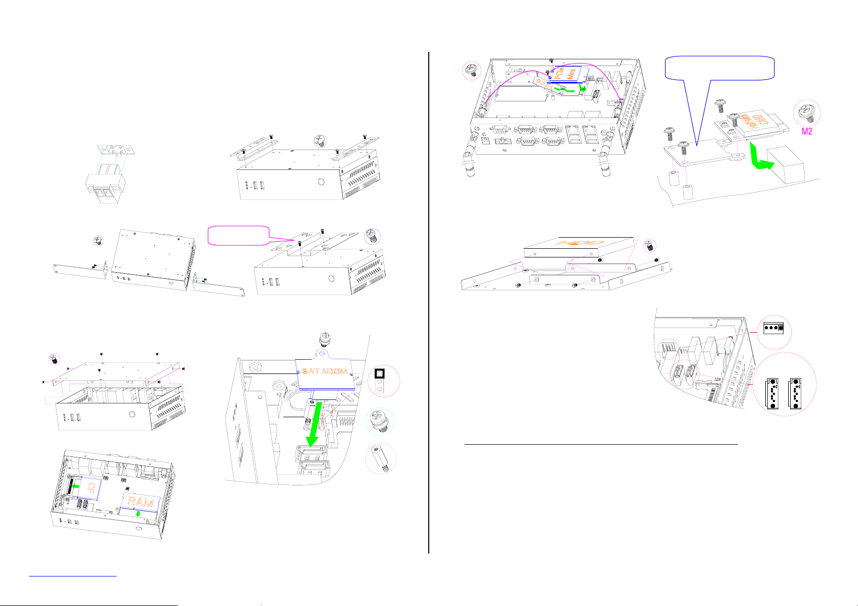
7. FX5406x Power Input and Mounting
Use terminal block for
Rack Mounting (FX5403K1 kit, Optional)
ower input
Wall Mounting (2 pieces of metal with 4 screws)
VESA 75/100mm
Standard
Panel Back Mounting (FX5504K1 kit, Optional)
8. Installing Devices into FX5406x
Step 1: Open the Bottom Cover (6 screws)
Step 2: Installing CF & DDR3 Modules
Step 3: Installing SATA DOM (optional) on SATA 1 connector
if necessary.
Note 1: SATA 2 connector is used for internal SATA hard disk
and SATA 1 connector is used for SATA DOM or
SATA DVDROM for OS installation.
Note 2: Please refer to manual for setting JP2 to proper
position when using SATA DOM.
JP2
Step 4-1: Installing mini PCIe module,
SIM Card, and Antenna(s)
Step 5-1: Installing SATA HDD (4 Screws)
Step 5-2: Connecting power cable to CN1 of main
board and signal cable to SATA 2 for
SATA HDD. (As the right figure shown)
Step 6: Close case with reverse procedures of open the case.
Half size mini PCIe adapter
(Optional)
Step 4-2: Installing half-size mini PCIe
module if necessary.
CN1
SATA2 SATA1
End of Document
www.fabiatech.com
©2011 FabiaTech Corporation
 Loading...