

Faber SCLX3615BKNBB Installation manual
SCIROCCO LUX
Installation Instructions
Use and Care Information
Instructions d'installation
Utilisez et d'entretien
SCLX3015BKNB-B
SCLX3615BKNB-B
SCLX3015SSNB-B
SCLX3615SSNB-B

READ AND SAVE THESE INSTRUCTIONS BEFORE YOU
START INSTALLING THIS RANGEHOOD
WARNING: - TO REDUCE THE RISK OF A RANGE TOP GREASE FIRE:
a) Never leave surface units unattended at high settings. Boilovers cause smoking and
greasy spillovers that may ignite. Heat oils slowly on low or medium setting.
b)AlwaysturnhoodONwhencookingathighheatorwhenambeingfood(i.e.Crepes
Suzette, Cherries Jubilee, Peppercorn Beef Flambé).
c) Clean ventilating fans frequently. Grease should not be allowed to accumulate on fan
orlter.
d) Use proper pan size. Always use cookware appropriate for the size of the surface element.
WARNING: - TO REDUCE THE RISK OF INJURY TO PERSONS IN THE EVENT OF A
RANGE TOP GREASE FIRE, OBSERVE THE FOLLOWING*:
a)SMOTHERFLAMESwithaclose-ttinglid,cookiesheet,ormetaltray,thenturnofftheburner.
BECAREFULTOPREVENTBURNS.IftheamesdonotgooutimmediatelyEVACUATE
AND CALL THE FIRE DEPARTMENT.
b) NEVER PICK UP A FLAMING PAN - You may be burned.
c) DO NOT USE WATER, including wet dishcloths or towels - a violent steam explosion will
result.
d) Use an extinguisher ONLY if:
1. You know you have a Class ABC extinguisher, and you already know how to operate it.
2. Thereissmallandcontainedintheareawhereitstarted.
3. Theredepartmentisbeingcalled.
4. Youcanghttherewithyourbacktoanexit.
* Based on "Kitchen Firesafety Tips" published by NFPA
WARNING - TO REDUCE THE RISK OF FIRE OR ELECTRIC SHOCK, do not use this fan
with any solid-state speed control device.
WARNING - TO REDUCE THE RISK OF FIRE, ELECTRICAL SHOCK, OR INJURY TO
PERSONS, OBSERVE THE FOLLOWING:
1. Use this unit only in the manner intended by the manufacturer. If you have any
questions, contact the manufacturer.
2. Before servicing or cleaning unit, switch power off at service panel and lock the
service disconnecting means to prevent power from being switched on accidentally. When the service disconnecting means cannot be locked, securely fasten a
prominent warning device, such as a tag, to the service panel.
CAUTION: For General Ventilating Use Only. Do Not Use To Exhaust Hazardous or
Explosive Materials and Vapors.
WARNING - TO REDUCE THE RISK OF FIRE, ELECTRICAL SHOCK, OR INJURY TO
PERSONS, OBSERVE THE FOLLOWING:
1. InstallationWorkAndElectricalWiringMustBeDoneByQualiedPerson(s)InAccor-
dance With All Applicable Codes And Standards, Including Fire-Rated Construction.
2. Sufcient air is neededfor proper combustion andexhausting of gases through
theue(chimney) of fuel burning equipmenttopreventbackdrafting. Follow the
heating equipment manufacturer's guideline and safety standards such as those
publishedby theNational Fire ProtectionAssociation (NFPA),and the American
SocietyforHeating,RefrigerationandAirConditioningEngineers(ASHRAE),and
the local code authorities.
2

!
3. When cutting or drilling into wall or ceiling, do not damage electrical wiring and
other hidden utilities.
4. Ducted fans must always be vented to the outdoors.
ALL WALL AND FLOOR OPENINGS WHERE THE RANGEHOOD IS INSTALLED
MUST BE SEALED.
Consult the cooktop or range installation instructions given by the manufacturer before making
any cutouts. MOBILE HOME INSTALLATION The installation of this rangehood must conform
to the Manufactured Home Construction and Safety Standards, Title 24 CFR, Part 3280 (formerly
Federal Standard for Mobile Home Construction and Safety, Title 24, HUD, Part 280). See
Electrical Requirements.
VENTING REQUIREMENTS
Determine which venting method is best for your application. Ductwork can extend either through
the wall or the oor.
The length of the ductwork and the number of elbows should be kept to a minimum to provide ef-
cient performance. The size of the ductwork should be uniform. Do not install two elbows together.
Use duct tape to seal all joints in the ductwork system. Use caulking to seal exterior wall or oor
opening around the cap.
Flexible ductwork is not recommended. Flexible ductwork creates back pressure and air
turbulence that greatly reduces performance.
Make sure there is proper clearance within the wall or oor for exhaust duct before making cutouts.
Do not cut a joist or stud unless absolutely necessary. If a joist or stud must be cut, then a supporting frame must be constructed.
WARNING - To Reduce The Risk Of Fire, Use Only Metal Ductwork.
CAUTION-Toreduceriskofreandtoproperlyexhaustair,besuretoductairoutside–Do
not vent exhaust air into spaces within walls or ceilings or into attics, crawl spaces, or garages.
Cold Weather installations
An additional back draft damper should be installed to minimize backward cold air ow and a
nonmetallic thermal break should be installed to minimize conduction of outside temperatures
as part of the vent system. The damper should be on the cold air side of the thermal break.
The break should be as close as possible to where the vent system enters the heated portion
of the house.
WARNING
• Venting system MUST terminate outside the home.
• DO NOT terminate the ductwork in an attic or other enclosed space.
• DO NOT use 4" laundry-type wall caps.
• Flexible-type ductwork is not recommended.
• DO NOT obstruct the ow of combustion and ventilation air.
• Failure to follow venting requirements may result in a re.
3

WARNING
!
• Electrical ground is required on this rangehood.
• If cold water pipe is interrupted by plastic, nonmetallic gaskets or other materials, DO
NOT use for grounding.
• DO NOT ground to a gas pipe.
• DO NOT have a fuse in the neutral or grounding circuit. A fuse in the neutral or
grounding circuit could result in electrical shock.
• Check with a qualied electrician if you are in doubt as to whether the rangehood is
properly grounded.
• Failure to follow electrical requirements may result in a re.
4
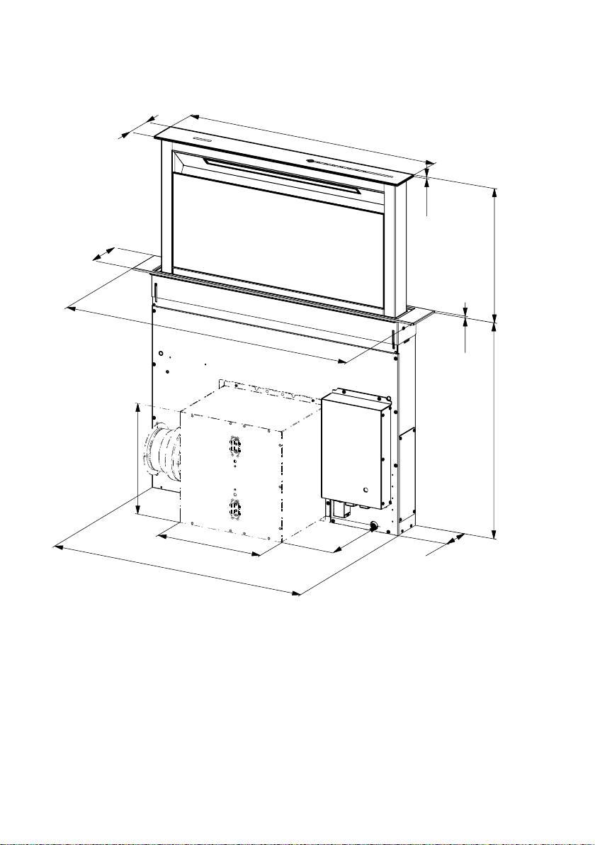
RANGEHOOD DIMENSIONS
“
“
11/16
3
“
3/4
4
25
1/4
“ - 31
1/4
”
3/16
“
16“
30” - 36”
1/4
“
27
7/16
“
1/16
13
25
9/16
13
“ - 31
1/16
9/16
9
13/16
“
4“
“
“
5
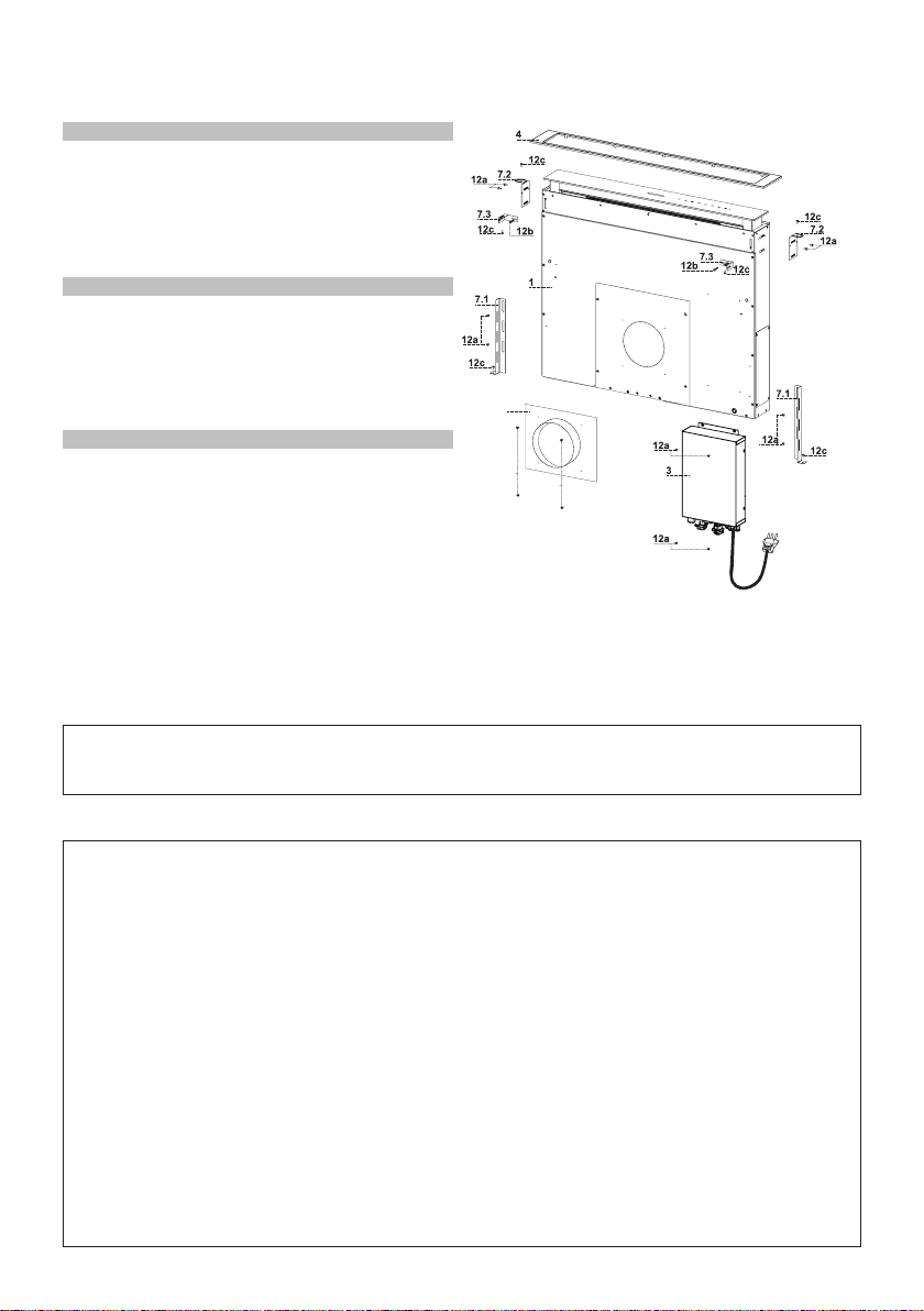
MAIN PARTS
Components
Ref. Qty. Product Components
1 1 Hood Canopy complete with:
Controls, Light, Filters.
3 1 Electric unit.
4 1 Top Frame
6 1 Duct Collar 10" duct collar used
with Remote Blowers
Ref. Qty. Installation Components
7.1 2 Lower Fixing Bracket
7.2 2 Top Side Fixing Bracket
7.3 2 Top Front Bracket
12a 16 Screws 1/8" x 3/8"
12b 6 Screws 3/16" x 5/16"
12c 8 Screws 3/16" x 9/16"
Qty. Documentation
1 Instruction Manual
10" duct collar used with Remote Blowers
12b
12b
5
- 6" Round Metal ductwork .
Parts needed
Recirculation Kit - sku # DUCTSCIR
Recirculation Vent Kit - Activated Charcoal Filter - FILTERSCIR
Internal Blower model - IBDD600-B
Remote Blower model - RB900, RB1200 (WIREBOX for Remote Blower included)
Wireless Remote Control - REMCTRL
Wiring box for Remote Blower - WIREBOXSCLX
6
AvailableAccessories(Purchasedseparately)
Installation Instructions
INSTALLATION
This Hood is set up to be fitted inside the kitchen unit in:
• Ducting version: Evacuation to the outside.
Sequence of operations - Installation
• Drilling the Support Surface and Fitting the Hood
• Connections
• Functional Check
• Disposal of Packaging
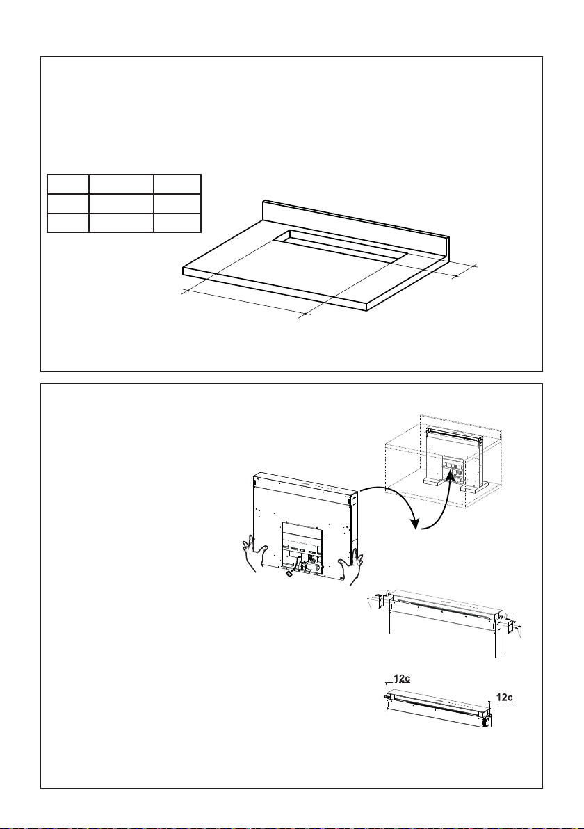
Drilling the Support Surface
X
812
1
FOR YOUR SAFETY:
WARNING Before beginning the installation, switch power off at service panel and lock the service
disconnecting means to prevent power from being switched on accidentally. When the service
disconnecting means cannot be locked, securely fasten a prominent warning device, such as a tag,
to the service panel.
Hood X Y
30" 25 15/16" 4 5/16"
36" 31 15/16" 4 5/16"
The minimum distance between the opening for the cooktop and the one for the hood must be of at
least 1 3/16" - 1 15/16" according to the strength of the material used for the working top.
Cutout Dimensions
Y
X
2
• Insert the Hood Canopy from below into the countertop
cutout, drilled as described above.
• With the aid of a support,
lift the Hood Canopy until
the front comes out of the
countertop.
• Insert the Brackets
7.2, as indicated in
the gure, into the
slots provided and x
them with the screws
12a provided.
• Center the Hood
Canopy with respect
to the Cooktop slot.
• Using the 2 screws 12c provided, secure the
Hood Canopy to the countertop and remove
the supports.
Warning:
If the countertop is made from a material that does not allow the screws 12c to be inserted, use
a small amount of silicone to glue the Brackets 7.2 to the top and allow it to dry completely
before proceeding with installation.
Inserting the Hood Canopy into the countertop from below
7
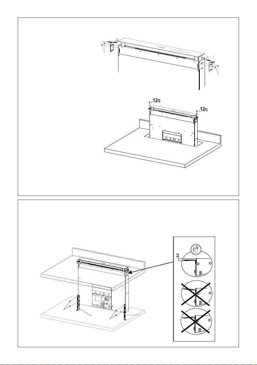
Fixing the Lower Brackets
3
Inserting the Hood Canopy into the countertop from above
• Insert the Brackets 7.2, as
indicated in the gure, into
the slots provided and x them
with the screws 12a provided.
• Insert the Hood Canopy into the
countertop, drilled as described
above.
• Center the Hood Canopy with
respect to the cooktop slot.
• Secure the Hood Canopy with
the 2 screws 12c provided.
Warning:
If the countertop is made from a material that does not allow the screws 12c to be inserted,
use a small amount of silicone to glue the Brackets 7.2 to the top and allow it to dry completely
before proceeding with installation.
4
• Screw the brackets 7.1 to the front of the Hood Canopy using the screws 12a provided.
• Before tightening the Brackets completely, make all the adjustments to allow them to rest on
the lower base of the Cabinet Base to avoid deformation of the upper brackets 7.2 as shown
in the gure.
Securing the Lower Brackets
12a
8
7.1
12a
7.1
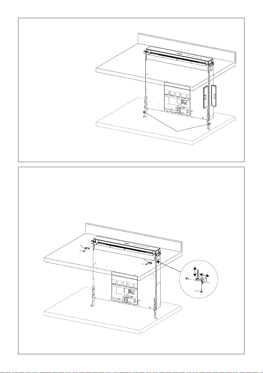
12a
7.1
12a
7.1
Fixing the Lower Brackets
5
Fixing the Squaring Brackets
• With the aid of a level,
• Tighten the screws 12a
set the Hood Canopy
level vertically and
secure it to the Lower
Surface using 2 screws
12c provided.
completely.
Leveling and Securing the Lower Brackets
12c
6
• Screw the brackets 7.3 to the Hood Canopy using the screws 12b provided, without
tightening completely.
• Using the screws 12c provided, fasten the other part of the brackets 7.3 either to the side
walls of the unit or to the lower part of the cooktop.
• Tighten the screws 12c and 12b completely.
Securing the Squaring Brackets
7.3
12b
7.3
12b
12c
9
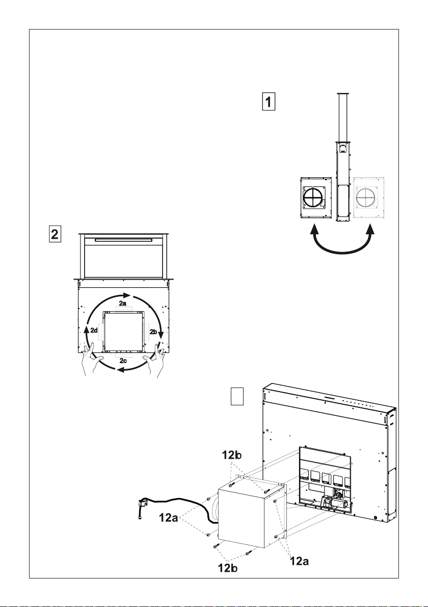
7a
CAUTION - To Reduce The Risk Of Fire And Electric Shock, Install This Down Draft Only With
Integral Blowers IBDD600-B Manufactured by Faber.
• Installation of the Internal Blower (1) at the front or rear must
be decided according to the position of the cooktop, making
sure that the plug is properly positioned.
Internal Blower Installation
• The Internal Blower can be rotated as shown in the
gure 2 for multiple venting directions..
• Screw the Internal Blower to the Hood
Canopy using the screws 12a and 12b
provided as shown in the gure.
10
3
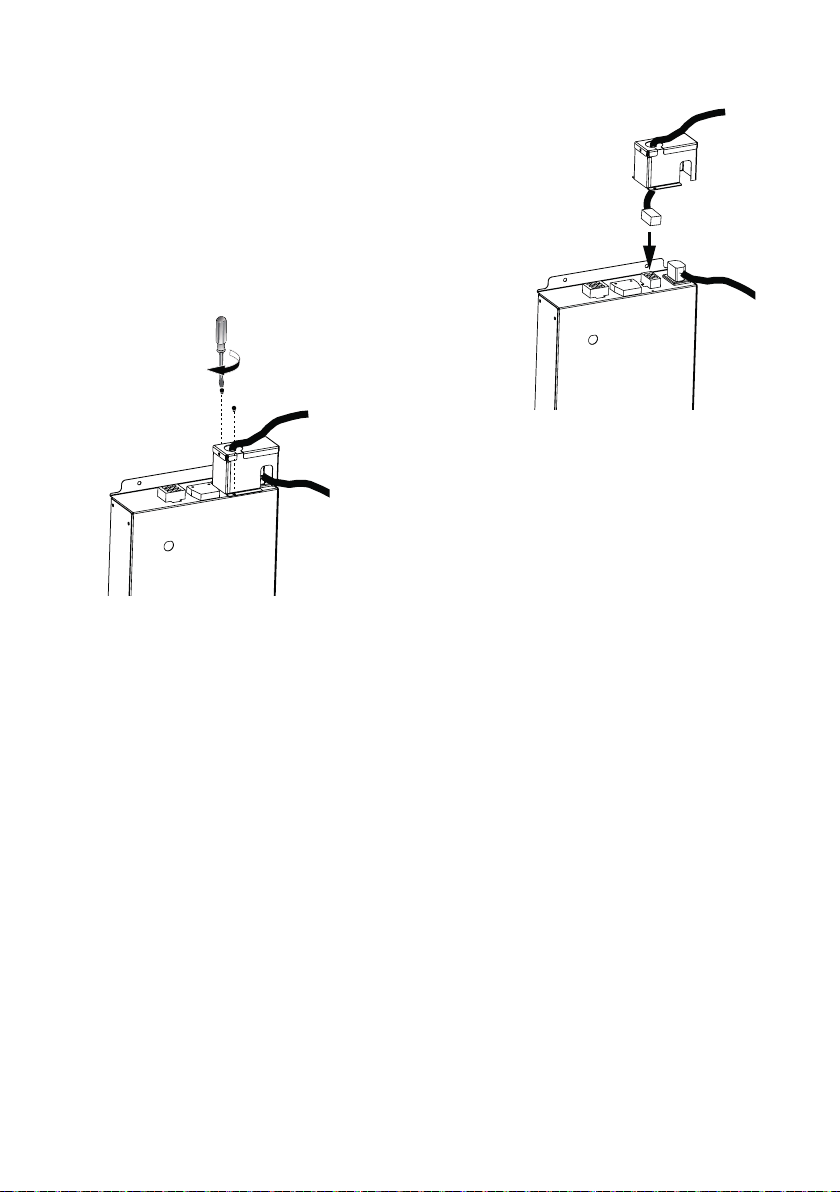
• Connect the Wire Connector from the Blower with the
3
correct connector on the Electric Unit.
• Secure the Wire Connector from the Blower at the
Electric Unit with 2 screws.
11
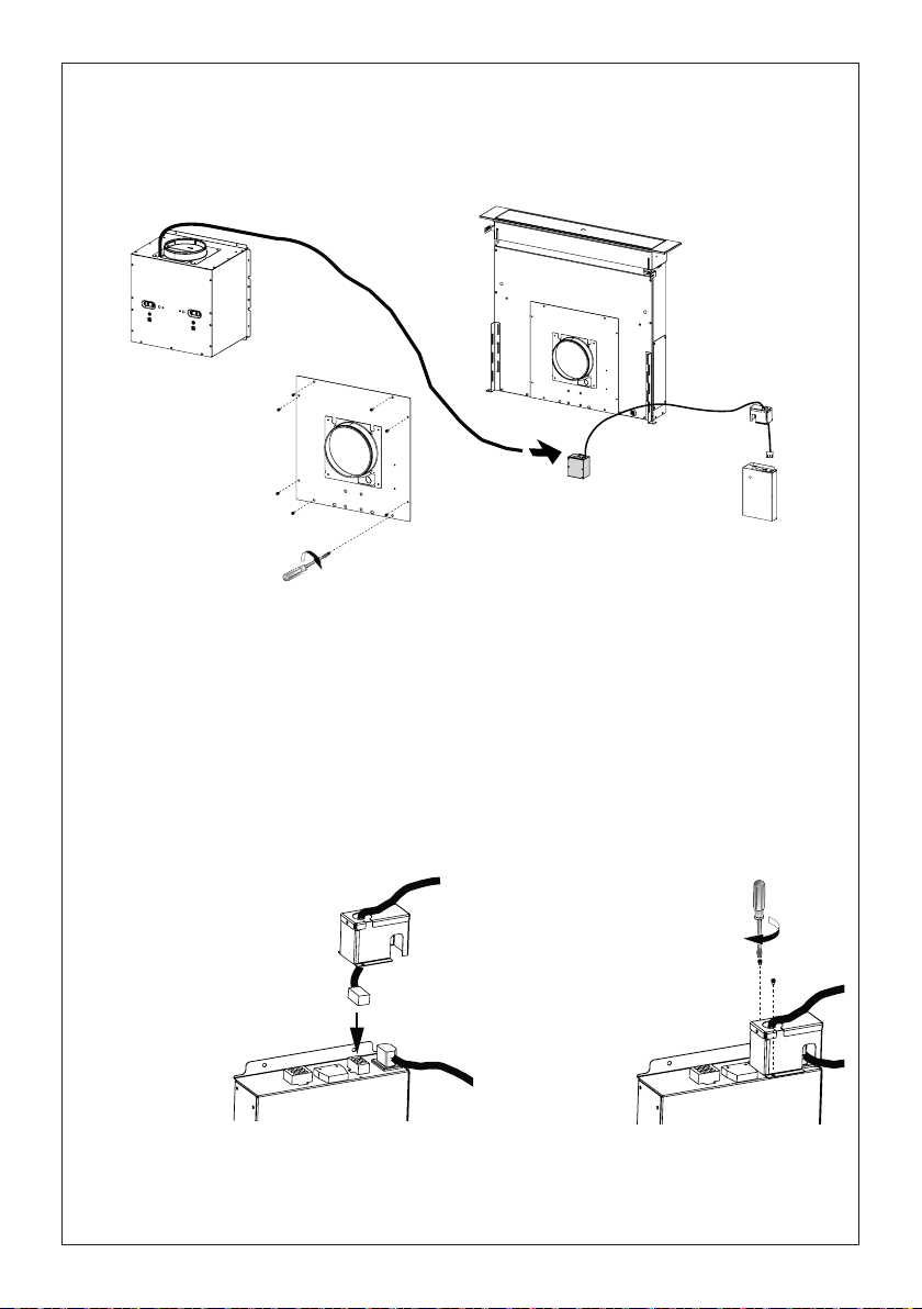
7b
3
CAUTION - To Reduce The Risk Of Fire And Electric Shock, Install This Down Draft Only With Remote
Blowers RB900, RB1200 Manufactured by Faber.
Installation of Remote Blower
4x
Connect the Remote Blower wiring to the connector of the Electric Unit.
Accessories needed:
- Remote Blower model - RB900, RB1200 (purchased separately).
- WIREBOXSCLX for Remote Blower (purchased separately).
Attention: Install the Wiring Box with two screws (provided) on a at and dry surface.
Connect the Remote Blower wiring plug connector to the connector of the Electric Unit.
Run 2-wire plus ground power cable from the Remote Blower to wiring box on the Cover according to
local codes and ordinances. Use Listed ttings.
• Connect the Wire Connector
from the Blower with the
correct connector on the
Electric Unit.
12
• Secure the Wire
Connector from the
Blower at the Electric
Unit with 2 screws.
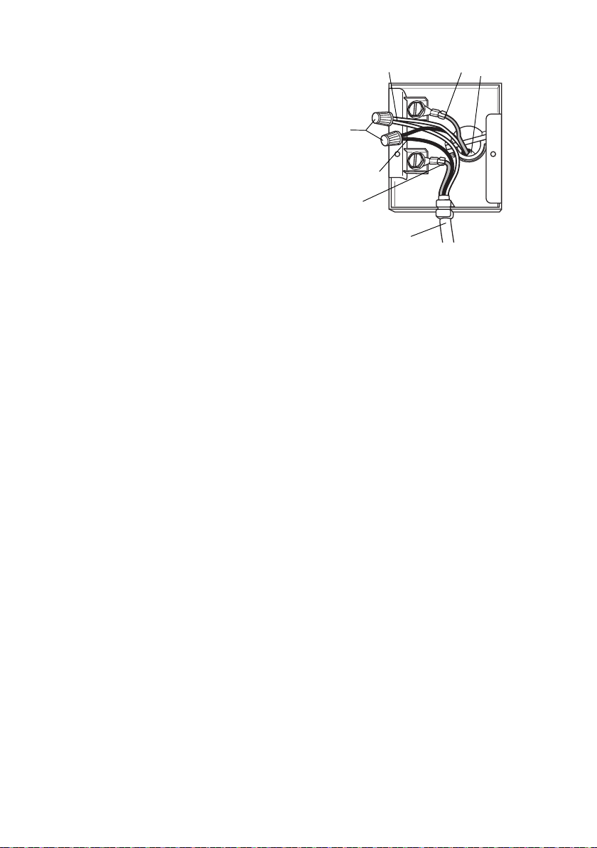
Installation of wiring connection
wiring
E
D
C
Remove the wiring electrical knockout using a at-blade
screwdriver. Feed the Power Supply Cable through the
electrical knockout.
Connect the Power Supply Cable to the Remote Blower.
Attach the White lead of the power supply (A) to the
White lead of the rangehood (D) with a twist-on type wire
connector. Attach the Black lead of the power supply to
the Black lead of the rangehood (B) with a twist-on type
wire connector (C). Connect the Green (E) (Green and
Yellow) ground wire under the Green grounding screws.
Replace the eld wiring compartment cover
Connect the ductwork to the damper and seal all connections with duct tape.
Turn the power supply on. Turn on the blower and light. If the rangehood does not operate, check that
the circuit breaker is not tripped or the house fuse blown. If the unit still does not operate, disconnect
the power supply and check that the wiring connections have been made properly.
B
E
Hood
A
13
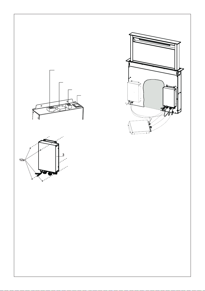
8
9 poles System
• Connect the wires coming out of the bottom right part
of the Hood Canopy to the corresponding connector
on the Electric Unit, taking care not to make any
wrong connections. Check the picture below.
Connector
Installation of Electrical Module
Command Flat
Connector
Blower Connector
Power supply
• Secure the Electric Unit to the Hood Canopy using the
screws 12a provided.
• The Electric Unit can be installed on the left or right of the
front of the hood canopy as shown above. It can also be
installed on the cabinet base if space allows.
Connect the ductwork to the damper and seal all connections with duct tape.
Turn the power supply on. Turn on the blower and light. If the rangehood does not operate, check that
the circuit breaker is not tripped or the house fuse blown. If the unit still does not operate, disconnect
the power supply and check that the wiring connections have been made properly.
"GROUNDING INSTRUCTIONS
This appliance must be grounded. In the event of an electrical short circuit, grounding reduces
the risk of electric shock by providing an escape wire for the electric current. This appliance is
equipped with a cord having a grounding wire with a grounding plug. The plug must be plugged
into an outlet that is properly installed and grounded.
WARNING - Improper grounding can result in a risk of electric shock.
Consult a qualied electrician if the grounding instructions are not completely understood, or if
doubt exists as to whether the appliance is properly grounded.
Do not use an extension cord. If the power supply cord is too short, have a qualied electrician
install an outlet near the appliance."
Warning..: Do not install the product in such a way that the electric unit is in contact with the oor.
14
 Loading...