

Page 1

Installation manual
Relaxed M Smart
Relaxed L Smart
ENG
40010635-2010
Page 2
Installation manual Relaxed M,L Smart
1 < < < <
Page 3
Installation manual Relaxed M,L Smart
2 < < < <
Page 4
Installation manual Relaxed M,L Smart
1.1
1.2
1.3
1.4
1.5
1.6
3 < < < <
Page 5
Installation manual Relaxed M,L Smart
1.7
2.0
2.1
2.2
2.3
2.4
2.5
A C B
1
2
4 < < < <
Page 6
Installation manual Relaxed M,L Smart
5 < < < <
Page 7
Installation manual Relaxed M,L Smart
1 Dear user
Congratulations on your purchase of a Faber fire! A
quality product from which you will experience
warmth and atmosphere for many years. We
recommend that you read this manual carefully
before using the fireplace. If any problem arises
despite our strict quality control, you can always
contact your dealer or Glen Dimplex Benelux B.V.
For any warranty claims, it is essential you first
register your fireplace. During this registration,
you’ll find all information regarding our warranty.
Please note!
The details of your fireplace can be found in
the user manual.
You can register your fire at: www.faberfires.com
Glen Dimplex Benelux B.V.
Address: Saturnus 8
NL-8448 CC
Heerenveen
Tel: +31 (0)513 656 500
Email: contact@faberfires.com
Info: www.faberfires.com
1.1 Introduction
Installation and maintenance of the appliance must
be carried out by a professional with proven
knowledge and competence. A professional takes
into account all technical aspects such as heat
radiation and gas connection as well as flue gas
exhaust requirements.
Where the installation instructions are not clear,
national/local regulations must be followed.
1.2 Check
Check the fireplace for transport damage and
immediately report any damage to your supplier.
1.3 CE Declaration
We hereby declare that Glen Dimplex Benelux B.V.
released Faber gas-atmosphere heating appliance
by its design and construction method complies
with the Regulation (EU): 2016/426 and (EU)
2015/1188.
Product: gas room heater
Model: Relaxed M Smart
Relaxed L Smart
This declaration will become null and void as soon
as the unit is in any way modified without written
authorization of Glen Dimplex Benelux B.V.
2 Safety instructions
Please note!
It is advisable to always install a screen for the
fireplace if children, elderly or disabled people are
present in the same room as the fireplace. If
regularly vulnerable persons can be present in the
room without supervision, sufficient protection
must always be placed around the fireplace.
This appliance must be installed according
with the rules in force and used only in a
sufficiently space.
The appliance must be checked annually
in accordance with this installation
manual and the applicable national and
local regulations.
Ensure that the data on the type label
matches the local gas type and pressure.
The appliance is designed for atmosphere
and heating purposes. This means that all
visible surfaces, including the glass, can
become hotter than 100°C. An exception
by free standing models is the underside
of the fireplace and the control buttons.
Do not use the remote control and / or
app outside the room where the fire is
located. So that you are always aware of
the situation around the fireplace when it
is being operated.
The settings and the construction of the
fireplace must not be changed!
Do not place extra imitation wood or
other material on the burner or in the
combustion chamber.
Do not place any combustible materials
within 0,5m of the radiation area of the
fire.
Through the natural air circulation of the
fireplace moisture and uncured volatile
components from paint, building
materials and carpeted floors, etc. are
attracted. These parts can settle as soot
on cold surfaces. Therefore do not light
the fireplace shortly after installation.
2.1 Using the fire for the first time
Provide extra ventilation and open all the windows
of the room during the initial start-up of the fire.
Let the fire burn at the highest setting for a few
hours so that the paint gets the chance to harden
and any released vapours are safely removed. Keep
vulnerable people and pets out of this room during
this process.
6 < < < <
Page 8
Installation manual Relaxed M,L Smart
3 Installation requirements
3.1 Appliance
This appliance may not be installed in a
chlorine-containing environment. (Pools
etc.).
This appliance must be built into an
existing or new false chimney.
For appliances with flexible gas pipes, the
control unit (fig. 1.3) is placed on the right
side of the crate for transport reasons.
Detach and mount it together with the
remote access door in as low as possible
position in the false chimney.
(To prevent damage to cables and pipes
during transport, they are bound together
by tie wraps. Remove these to ensure
proper operation of the appliance.)
If desired, a 2 meter pipe set is available
(article number 20900715).
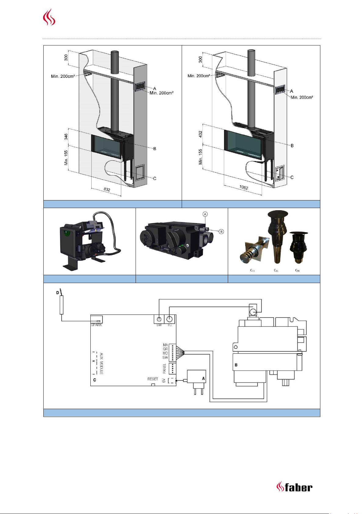
3.2 False chimney
The false chimney should be of non-
combustible material.
The space above the fire should always be
ventilated using grids with minimal free
passage of 200cm² per grid.
The false chimney construction should not
rest on the build-in frame of the fireplace
(see fig. 1.1-B).
3.3 Discharge and outlet requirements
First, carry out a flue calculation (see chapter 11)
and place the right flue restrictor before installing
the outlet! (Generally a 30mm flue restrictor is
installed).
For supply and discharge always use the
prescribed and to be supplied Faber flue
materials. Please contact Glen Dimplex
Benelux B.V.. Only with use of these
materials Faber can guarantee proper
performance.
The distance to combustible materials
must be min. 50mm, calculated from
outside of the flue material (EN 1856-1
T600 N1 D Vm – L20040 O(50)).
Outlets (fig. 1.5)
The balanced flue pipe for combined air supply and
discharge can use a wall terminal or a roof
terminal. Verify that the desired outlet meets the
local regulations regarding pollution and
ventilation openings.
Please note!
For proper functioning, the outlet must at
least be 0,5m away from:
Corners of the building;
Roof overhangs and balconies;
Roof edges (with the exception of the
ridge edge, see chapter 15).
C11, outlet via facade
Through a wall or façade, use a Faber wall outlet.
Depending on the flue calculation this can be
100/150mm or 130/200mm.
C31, outlet via roof
For a (flat) roof, use a Faber roof outlet with a
diameter of 100/150mm.
C91, existing chimney
For an existing chimney, use a Faber chimney
outlet with a diameter of 100/150mm.
In this case the existing chimney acts as air inlet an
inserted flexible stainless steel pipe discharges the
flue gas. The top (Faber chimney cover plate) and
the bottom (Faber chimney connection set) should
be airtight.
Depending on the calculated flue diameter, you
must use a flexible stainless steel pipe of
Ø100mm (article number AJ005503) or Ø130mm
(article number AJ005603) as specified by Faber.
For this, contact Glen Dimplex Benelux B.V.
Please note!
The minimum chimney diameter for a
130mm flexible stainless steel pipe must
be 200x200mm and for a 100mm flexible
stainless steel pipe and 150x150mm.
Don’t connect more than one fire at the
existing chimney.
The chimney must be in good condition:
o No leakage;
o Well cleaned.
For more information about the connections to
existing chimney ducts, please request the
installation instructions “Chimney Connection Set”.
7 < < < <
Page 9
Installation manual Relaxed M,L Smart
4 Preparation and installation
instructions
4.1 Gas connection
The gas connection must comply with the
applicable local standards.
Please note!
Provide a flexible gas connection with at
least 0,5m extra length, so that the
control unit can be removed for
installation and service!
Calculate the gas pipe so that no
pressure drop occurs.
We advise using a gas connection directly from the
gas meter to the appliance, with a shut-off valve in
the proximity of the appliance, which must always
be freely accessible. Position the gas connection so
that it is easily accessible for service and the
burner unit can be disassembled at any time.
4.2 Electrical connection
Install a 230VAC/50Hz wall socket near the
fireplace for connecting the control unit.
See fig. 1.6 for the wiring diagram:
A = Adapter (6V)
B = Gas valve
C = Receiver
D = Ignition pin
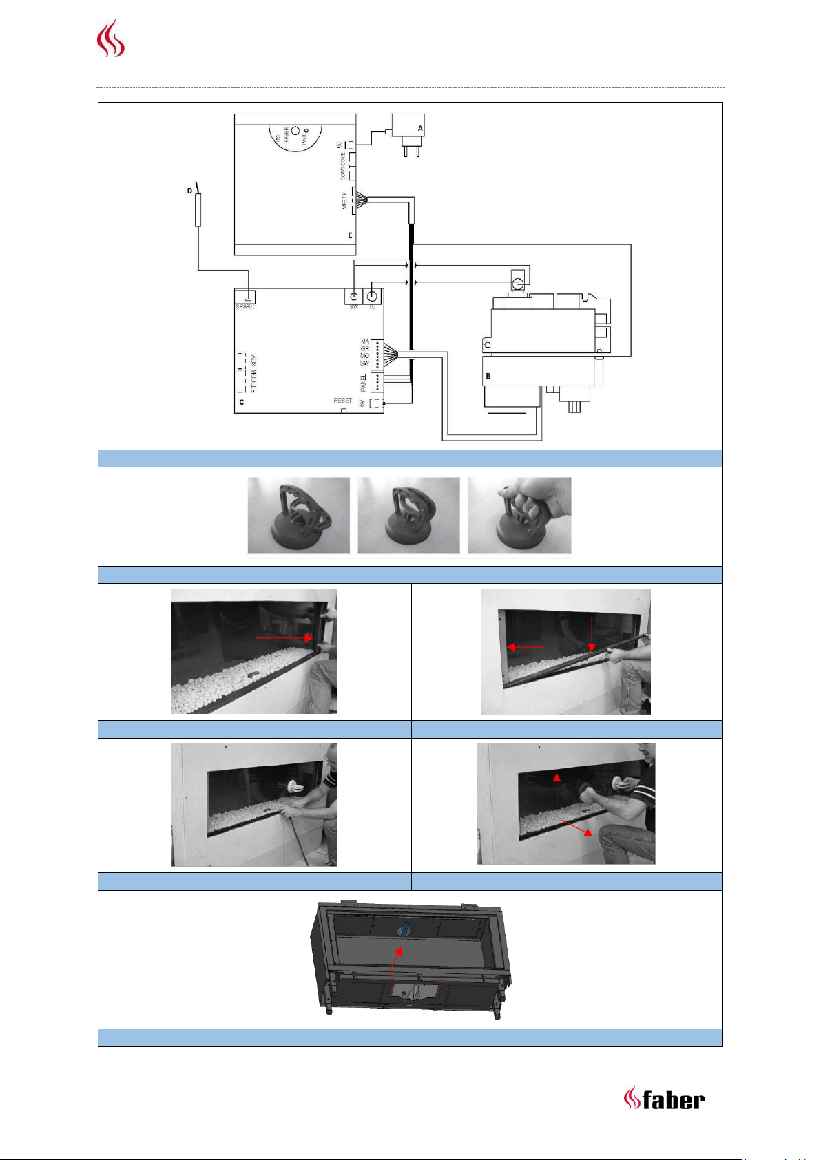
See fig. 1.7 for the wiring diagram with I.T.C
(optional):
A = Adapter (6V)
B = Gas valve
C = Receiver
D = Ignition pin
E = I.T.C. (Intelligent Technical Controller)
4.3 Smart Home installation
Please note
This is only possible if the fire is equipped
with I.T.C!
The controller can be connected to an external
source, such as a Domotica system, by using a
Faber Interface Unit (article number A9323000).
4.4 Preparing the fireplace
Remove the fireplace from its packaging.
Ensure that the gas supply pipes under
the appliance are not damaged.
Remove the glass and any mouldings,
store them at a safe place and remove the
packaged parts from the fireplace.
Prepare the gas connection on the gas
valve.
4.5 Positioning the fireplace
Take into account the installation requirements
(see chapter 3). Place the fireplace at the right
place and level it (see fig. 1.1-C or 1.2-C).
Rough height adjustment:
With the adjustable legs.
Accurate height adjustment:
With the adjustable feet.
4.6 Installing the flue pipes
Install the flue pipes according to the installation
manual supplied with the appliance (40011968)!
The distance to combustible materials
must be min. 50mm, calculated from the
outside of the flue pipe.
Never start immediately with length-
adjustable concentric flue pipe on the
appliance.
Horizontal sections should be installed to
allow a slope towards the appliance
(3 degrees).
Built the system from the appliance. If this
is not possible you can make use of an
extendable adapter section.
For fitting of the flue system, the 0,5m
length-adjustable pipe must be used.
Make sure that the inner pipe is always
15mm longer than the outer pipe. Walland roof terminal can also be cut. These
components must be secured with a selftapping screw.
4.7 Constructing the false chimney
Before positioning the false chimney, we advise to
perform a functional test with the fireplace as
defined in chapter 7 “Checking the installation”.
False chimney
Construct the false chimney of non-
combustible material in combination with
metal profiles or of masonry/concrete
blocks.
Always use a lintel or reinforcing bars
while bricking the false chimney. They
should not be placed directly on the
fireplace.
Make sure that the fireplace never
functions as a load-bearing construction,
because of the expansion of the fireplace
through warmth.
8 < < < <
Page 10

Installation manual Relaxed M,L Smart
Ventilation
Correct ventilation prevents damaging overheating
of the gas control block and its electronics and also
limits the temperature of the convection air. Use
the (optional) supplied Faber ventilation grids
(article number A9296400) or a similar alternative
with a minimum free passage of 200cm² per grid,
in the space above the fire, when building the false
chimney. Within the false chimney, an horizontal
screen plate, made of non-combustible material,
must be installed just above the ventilation
openings. (see fig. 1.0-A).
Installation and finishing
Please note!
Take into account a minimum distance of
2mm due to expansion of the fireplace.
Take into account the thickness of any
finishing layer!
Construct the false chimney against the build-in
frame, see fig. 1.0-B).
5 Removing glass
Remove the vertical cover strips (see fig.
2.1-A).
Remove the horizontal cover strip (see fig.
2.2-B).
Place the suction cups on the glass (see
fig. 2.0).
Remove the sealing cord (see fig. 2.3).
Remove the vertical strips (see fig. 2.2-C).
Carefully lift the glass and pull the
underside towards you (see fig. 2.4).
For replacing the glass repeat the steps in reverse
order.
Please note!
Avoid fingerprints on the glass, these are no
longer removable once the fire is used.
6 Placing decoration material
Please note!
It is not permitted to use other or to add
more material in the combustion
chamber.
Do not throw the decoration material on
the burner at once. It is possible that the
burner gets clogged.
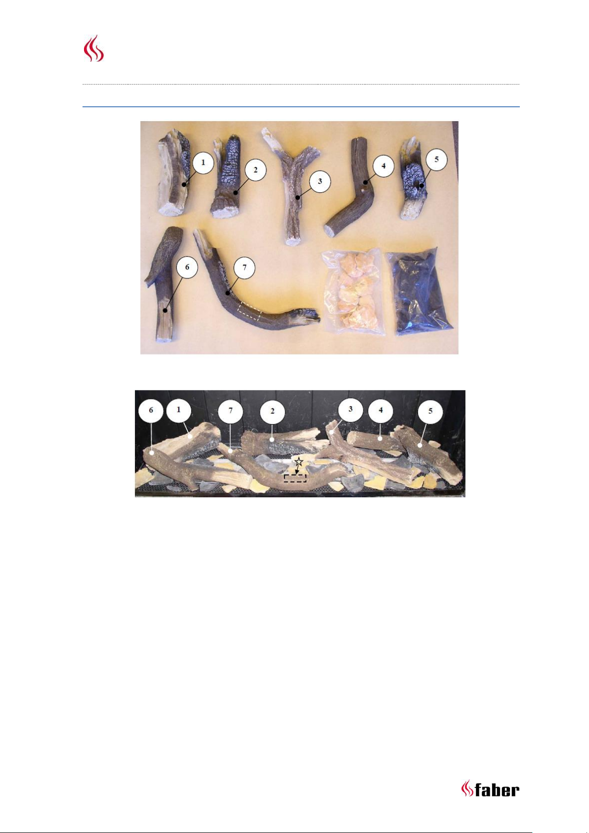
See the supplied decoration instruction card or
chapter 18.1 or 18.2:
Place part of the ash material at the
burner and the cover plate.
Place the log set.
Divide the rest of the ash material at the
burner and the cover plate.
Please note!
Keep the pilot flame free from ash material.
Start the fireplace as described in the user
manual.
Assess whether the flame distribution is
good. Move or remove any ash material
to create a nice glow bed.
Install the front glass and check the fire
image.
7 Checking the installation
Checking for gas leaks
Check with a gas leak finder all connections and
pipes for gas leakage.
Check primary- and burner pressure
Check if the primary pressure correspond to the
data on the rating plate.
Measuring the primary pressure:
Close the shutoff valve. Turn the
measuring nipple “A” (fig. 1.4) a few turns
to open and connect a measuring hose to
the gas valve.
Take this measurement when the
fireplace runs at high and low settings.
Do not use the device if the pressure
deviates (+20% or -20%).
Measuring the burner pressure:
Check the burner pressure only with proper
primary pressure.
Turn measuring nipple “B” (see fig. 1.4)
some turns open and connect a measuring
hose to the gas valve.
The pressure must correspond to the
value indicated in the technical
specifications of this manual. In case of
deviation contact the manufacturer.
Please note!
Close both pressure measuring nipples and
check for gas leakage.
Check ignition and burner
Ignite the fireplace by using the remote control as
described in the user manual and test all burner
possibilities.
9 < < < <
Page 11
Installation manual Relaxed M,L Smart
7.1 Checking the flame image
Let the fireplace burn for at least 20 minutes at
highest setting and check the flame for:
flame distribution;
colour of the flames.
If one or both points are not acceptable then
check:
The position of the logs and/or the
amount of ash material.
The pipe connections for leaks.
(in case of blue flames);
That the correct flue restrictor is fitted
(see fig. 2.5);
The outlet:
o Wall terminal has the correct
position and side up;
o Roof terminal has the correct
position.
If the maximum lengths of the flue gas
outlet is not exceeded.
8 Instructions for client
Recommend that the fire should be
checked annually by a qualified specialist
to ensure the safe use and to guarantee a
long service life.
Provide instructions on the operation of:
o the appliance;
o the remote control;
o if present, the App and its
settings.
Give advice and instructions on care and
cleaning of the glass:
9 Annual maintenance
Check
Check and clean if necessary:
the combustion chamber;
the burner
the pilot flame;
the wooden logs for breakage;
the glass(es);
the outlet.
Replace ash material if necessary.
Cleaning
Remove the front glass (see chapter 5).
You can clean the glass with Faber glass polish.
This is a specially formulated cleaning agent that
can be ordered at authorized Faber dealers.
Never use aggressive cleaning agents or abrasive
products.
Please note!
Avoid fingerprints on the glass; these are no
longer removable once the fire is used.
Now carry out check-up as described in chapter 7.
For an extensive maintenance instruction
"maintenance protocol gas fires" see:
Emphasize the danger of fingerprint burns
at the glass.
Handover to customer:
o installation manual;
o user manual;
o decoration instruction card;
o suction cups;
o sample Faber glass polish.
10 < < < <
10 Conversion to other gas type
This can only be done by replacing the burner. To
do so, please contact your dealer. Always provide
the type and serial number of the appliance when
ordering.
Page 12
Installation manual Relaxed M,L Smart
11 Flue calculation
A simple way to calculate whether the exhaust
configuration is possible in combination with your
fireplace, use the “Faber Flue App V2”:
This is available free of charge and can be
downloaded via:
Internet:
Android and PC (Windows Store, (Windows 10)).
App Store:
iPhone, iPad and Mac.
Google Play:
Android smart phones and Android tablets.
Alternatively, you can use the calculation sheet
(see chapter 13).
The options for flue lengths and any flue restrictors
are defined in a restrictor table, see 11.1 till 11.2.
Start Length (STL), Total Vertical Height (TVH) and
Total Horizontal Length (THL) are used in the table.
Start length (STL):
The first part that is placed on the
fireplace and represents a certain value
(fig. 12.1, 12.2 and 12.3 A, N and F). You
can find this value in the upper row of the
restrictor table.
Total Vertical Height (TVH):
TVH is the height difference measured
from the top of the appliance to the
outlet. This can be measured or
determined in the building plan. For
clarification, see also the TVH indication in
the drawings (fig. 12.1, 12.2 and 12.3).
Total Horizontal Length (THL):
THL is the Total Horizontal Length and
consists of elbows and pipes entirely in
the horizontal plane. See elbows I, K and Q
and the elements H, J, L, M, P and R
(fig. 12.1 and 12.2).
Horizontal length:
The Horizontal Length consists of the
elements H, J, L, M, P and R (fig. 12.1 and
12.2).
Elbows 90° in the horizontal plane:
Horizontal elbows are elbows entirely in
the horizontal plane
(fig. 12.1, 12.2 and 12.3 I, K and Q).
Elbows 45° or 30° in the horizontal plane.
Horizontal elbows are elbows entirely in
the horizontal plane.
Elbows 90° vertical to horizontal:
These are 90° elbows, which proceed from
horizontal to vertical (fig. 12.2 and 12.3 G,
O and S).
Elbows 45° or 30° vertical to horizontal
plane:
These are 30° or 45° elbows vertically
offset less than 45° (fig. 12.1 B and D).
Pipes at an angle of inclination:
These are pipes vertically ascending at an
angle of 30° or 45° (fig. 12.1 C). Fill in only
in combination with at least two 30° or
45° elbows in the vertical part.
Restrictor table:
See restrictor table for the correct vertical
(TVH) and horizontal length (THL).
In case of an “X” or if the values are outside the
restrictor table, the combination is not permitted.
Then adjust TVH or THL.
If a value is indicated, check that the calculated STL
value is not lower than indicated in the restrictor
table. In this case STL must be adjusted.
The value found indicates the width of the flue
restrictor to be placed (“0” means no flue
restrictor). Generally a 30mm flue restrictor is
installed (see fig. 2.5).
11 < < < <
Page 13
Installation manual Relaxed M,L Smart
0,2 0,5 1 1 1 1 1
0 1 2 3 4 5 6 7 8 9 10
0 x x x x x x x x x x x
0,5 0.00 0.00 x x x x x x x x x
1 0.00 0.00 0.00 x x x x x x x x
1,5 0.00 0.00 0.00 0.00 x x x x x x x
2 30.00 0.00 0.00 0.00 0.00 x x x x x x
3 30.00 30.00 0.00 0.00 0.00 0.00 x x x x x
4 40.00 30.00 0.00 0.00 0.00 0.00 0.00 x x x x
5 40.00 40.00 30.00 0.00 0.00 0.00 0.00 x x x x
6 50.00 40.00 30.00 0.00 0.00 0.00 0.00 x x x x
7 50.00 50.00 40.00 30.00 0.00 0.00 0.00 x x x x
8 50.00 50.00 40.00 30.00 0.00 0.00 0.00 x x x x
9 65.00 50.00 50.00 40.00 30.00 0.00 0.00 x x x x
10 65.00 65.00 50.00 40.00 30.00 30.00 0.00 x x x x
11 65.00 65.00 50.00 50.00 40.00 30.00 0.00 x x x x
12 65.00 65.00 50.00 50.00 40.00 30.00 30.00 x x x x
13 65.00 65.00 50.00 50.00 40.00 30.00 30.00 x x x x
14 65.00 65.00 50.00 50.00 40.00 30.00 30.00 x x x x
15 65.00 65.00 50.00 50.00 40.00 30.00 30.00 x x x x
16 65.00 65.00 50.00 50.00 40.00 30.00 30.00 x x x x
17 65.00 65.00 50.00 50.00 40.00 30.00 30.00 x x x x
18 65.00 65.00 50.00 50.00 40.00 30.00 30.00 x x x x
19 65.00 65.00 50.00 50.00 40.00 30.00 30.00 x x x x
20 65.00 65.00 50.00 50.00 40.00 30.00 30.00 x x x x
21 65.00 65.00 50.00 50.00 40.00 30.00 30.00 x x x x
22 65.00 65.00 50.00 50.00 40.00 30.00 30.00 x x x x
23 65.00 65.00 50.00 50.00 40.00 30.00 30.00 x x x x
24 65.00 65.00 50.00 50.00 40.00 30.00 30.00 x x x x
25 65.00 65.00 50.00 50.00 40.00 30.00 x x x x x
26 65.00 65.00 50.00 50.00 40.00 x x x x x x
27 65.00 65.00 50.00 50.00 x x x x x x x
28 65.00 65.00 50.00 x x x x x x x x
29 65.00 65.00 x x x x x x x x x
30 65.00 x x x x x x x x x x
STL
THL
TVH
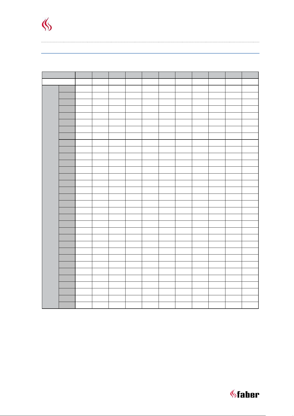
11.1 Restrictor table (100/150) Relaxed M Smart
Start length (STL) Vertical (TVH) and Horizontal (THL)
12 < < < <
Page 14

Installation manual Relaxed M,L Smart
0,2 0,5 1 1 1 1 1
0 1 2 3 4 5 6 7 8 9 10
0 x x x x x x x x x x x
0,5 x x x x x x x x x x x
1 0.00 0.00 0.00 x x x x x x x x
1,5 30.00 30.00 0.00 0.00 x x x x x x x
2 30.00 30.00 30.00 0.00 0.00 0.00 0.00 x x x x
3 40.00 30.00 30.00 30.00 0.00 0.00 0.00 x x x x
4 40.00 40.00 30.00 30.00 30.00 0.00 0.00 x x x x
5 50.00 40.00 40.00 30.00 30.00 30.00 0.00 x x x x
6 50.00 50.00 40.00 40.00 30.00 30.00 0.00 x x x x
7 50.00 50.00 50.00 40.00 40.00 40.00 0.00 x x x x
8 60.00 50.00 50.00 40.00 40.00 40.00 30.00 x x x x
9 60.00 60.00 50.00 50.00 40.00 40.00 30.00 x x x x
10 65.00 60.00 60.00 50.00 40.00 40.00 30.00 x x x x
11 65.00 65.00 60.00 50.00 50.00 40.00 30.00 x x x x
12 65.00 65.00 60.00 50.00 50.00 40.00 30.00 x x x x
13 65.00 65.00 60.00 50.00 50.00 40.00 30.00 x x x x
14 65.00 65.00 60.00 50.00 50.00 40.00 30.00 x x x x
15 65.00 65.00 60.00 50.00 50.00 40.00 30.00 x x x x
16 65.00 65.00 60.00 50.00 50.00 40.00 30.00 x x x x
17 65.00 65.00 60.00 50.00 50.00 40.00 30.00 x x x x
18 65.00 65.00 60.00 50.00 50.00 40.00 30.00 x x x x
19 65.00 65.00 60.00 50.00 50.00 40.00 30.00 x x x x
20 65.00 65.00 60.00 50.00 50.00 40.00 30.00 x x x x
21 65.00 65.00 60.00 50.00 50.00 40.00 30.00 x x x x
22 65.00 65.00 60.00 50.00 50.00 40.00 30.00 x x x x
23 65.00 65.00 60.00 50.00 50.00 40.00 30.00 x x x x
24 65.00 65.00 60.00 50.00 50.00 40.00 30.00 x x x x
25 65.00 65.00 60.00 50.00 50.00 40.00 x x x x x
26 65.00 65.00 60.00 50.00 50.00 x x x x x x
27 65.00 65.00 60.00 50.00 x x x x x x x
28 65.00 65.00 60.00 x x x x x x x x
29 65.00 65.00 x x x x x x x x x
30 65.00 x x x x x x x x x x
STL
THL
TVH
11.2 Restrictor table (100/150) Relaxed L Smart
Start length (STL) Vertical (TVH) and Horizontal (THL)
13 < < < <
Page 15

Installation manual Relaxed M,L Smart
12 Examples flue materials
14 < < < <
Page 16

Installation manual Relaxed M,L Smart
Starter length (STL)
First part on top of the appliance
Value
Value
Flue length from 0,1m till 0,45m
0,2
Flue length from 0,5m till 0,90m
0,5
Flue length from 1m till 1,4m
1
Flue length from 1,5m till 2m
1,5
Flue length 2m or more
2
Bend 90°
0,1
Bend 45°, 30° or 15°
0,2
Roof terminal
1
Wall terminal
0
……………………..
Total Vertical Height (TVH)
measured height
rounded value
…………………………………………………… meter
……………. meter
Total Horizontal Length (THL)
Calculation
Part
number
x
value
result
rounded value
Total Length in meters
………
x 1 ……………..
90° Bend, vertical to
horizontal
………
x
0,4
……………..
45° Bend, vertical to
horizontal
………
x
0,2
……………..
90° Bend in horizontal
direction
………
x
1,5
……………..
45° Bend in horizontal
direction
………
x 1 ……………..
flue pipes at an angle in
meters
………
x
0,7
……………..
Total
……………+
………………….. meter
13 Calculation sheet
15 < < < <
Page 17

Installation manual Relaxed M,L Smart
Search in the table at TVH and THL and enter the value that is found.
found value
………………………………
If the detected value is a number, check whether the completed STL is higher or equal to the value in
the table.
Is the STL value lower as specified in the table then the installation is not possible.
Solution: Start length to low, see for the minimum length in the top row of the table.
Is the found value X, then the installation is not possible.
Solution: Change the TVH or THL.
Results
Restrictor size = Value for the comma
………………….. mm
Extra information = Value behind the comma
mark
Install the air restrictor plate, see installation manual
0,1 Install adapter 100/150 direct on top of the fire
0,2
In case of wall terminal, install adapter 100/150 before the
last bend, in case of roof terminal just before the terminal.
0,3
In case of roof terminal (always size 100/150) install the
100/150 adapter just before the terminal.
Wall terminal 130/200
0,4
From the fire first an adjuster to 130/200 and 1 meter
130/200, after that reduce to 100/150 and everything
100/150.
0,5
16 < < < <
Page 18

Installation manual Relaxed M,L Smart
Symbol Unit
Reference gas/i nlet pressure G20-20 G30-30 G31-37 mbar
Emissi ons in space heati ng NOx 76 80 79 mg/kWh
input
(GVC)
Direct heating output
Nominal heat output P
nom
6,4 6,4 6,0 kW
Mini mum heat output (indic ati ve) P
min
3,4 3,4 3,2 kW
Useful effici ency (NCV)
At nominal heat output ꞃ
th,nom
88,7 88,7 88,7 %
At minimum heat output (i ndi cative) ꞃ
th,min
85,2 85,2 85,2 %
Appli ance input data
Input Hi 7,2 7,2 6,8 kW
0,77 0,215 0,272 m³/h
0,54 0,51 kg/h
Burner pressure at ful l mark 9 19,5 24 mbar
Power requirement for permanent pil ot light
Additional electricity consumption
At nominal heat output el
max
0 0 0 kW
At minimum heat output el
min
0 0 0 kW
In s tandby mode el
SB
0 0 0 kW
Energy-effici ency
Energy-effici ency cla ss B B B
Energy-effici ency i ndex EEI 85 85 85
Type heating output/control room temperature
no
no
nonoyes
no
Glen Dimplex Benelux Saturnus 8 Heerenveen The Netherlands
With mechani ca l control of the room temperature by
thermostat
Control of room temperature, with open
window detection
no
With electroni c control of the room temperature
With electroni c control of the room temperature plus day-
time switch
With optiona l remote control
yes
With electroni c control of the room temperature plus week-
time switch
0,15
0,15
kW
Other control options
One step heat output, no control of room temperature
Control of room temperature, with
presence detection
no
Two or more manuall y adjustable stages, no control of room
temperature
0,15
Gas rate at full mark
Power requirement for permanent pil ot light
(if a pplicable)
P
pilot
Gas connecti on
3/8"
Indi rect heating functiona lity
no
Category
II2H3+
Dia meter outl et/inl et
100/150
Technical data
Type indi cation(s )
Relaxed Smart M
Type appl iance
C11/C31/C91
14 Technical data
14.1 Relaxed M Smart
17 < < < <
Page 19

Installation manual Relaxed M,L Smart
Symbol Unit
Reference gas/i nlet pressure G20-20 G30-30 G31-37 mbar
Emissi ons in space heati ng NOx 49 52 54 mg/kWh
input
(GVC)
Direct heating output
Nominal heat output P
nom
7,1 7,1 7,1 kW
Mini mum heat output (indic ati ve) P
min
3,3 3,3 3,3 kW
Useful effici ency (NCV)
At nominal heat output ꞃ
th,nom
88,3 88,3 88,3 %
At minimum heat output (i ndi cative) ꞃ
th,min
82,7 82,7 82,7 %
Appli ance input data
Input Hi 8 8 8 kW
0,85 0,246 0,315 m³/h
0,62 590 kg/h
Burner pressure at ful l mark 10 23 28,6 mbar
Power requirement for permanent pil ot light
Additional electricity consumption
At nominal heat output el
max
0 0 0 kW
At minimum heat output el
min
0 0 0 kW
In s tandby mode el
SB
0 0 0 kW
Energy-effici ency
Energy-effici ency cla ss B B B
Energy-effici ency i ndex EEI 84 84 84
Type heating output/control room temperature
no
no
nonoyes
no
Dia meter outl et/inl et
100/150
Technical data
Type indi cation(s )
Relaxed Smart L
Type appl iance
C11/C31/C91
Gas connecti on
3/8"
Indi rect heating functiona lity
no
Category
II2H3+
Gas rate at full mark
Power requirement for permanent pil ot light
(if a pplicable)
P
pilot
0,15
0,15
kW
Other control options
One step heat output, no control of room temperature
Control of room temperature, with
presence detection
no
Two or more manuall y adjustable stages, no control of room
temperature
0,15
Glen Dimplex Benelux Saturnus 8 Heerenveen The Netherlands
With mechani ca l control of the room temperature by
thermostat
Control of room temperature, with open
window detection
no
With electroni c control of the room temperature
With electroni c control of the room temperature plus day-
time switch
With optiona l remote control
yes
With electroni c control of the room temperature plus week-
time switch
14.2 Relaxed L Smart
18 < < < <
Page 20

Installation manual Relaxed M,L Smart
Location
Position outlet
Distance mm
D
Under a gutter
500
E
Under a roof edge
500
F
Under a carport or balcony
500
G
Vertical downpipe
300
H
Inside and outside corners
500
J
From wall surface to a wall outlet
1000 K Two gable outlets against over each other
1000
L
Distance between two roof outlets
450
M
Two roof outlets above each other on a pitched roof
1000
N
Two gable outlets next to each other
1000
Short roof terminal.
Extension pipe over roof.
15 Outlet position
Please note!
These rules apply only for the proper functioning of the unit, for ventilation and environmental
protection you need to comply with the applicable rules as defined in the building regulations.
Only for existing
Chimney connection.
19 < < < <
Page 21

Installation manual Relaxed M,L Smart
16 Troubleshooting guide
20 < < < <
Page 22

Installation manual Relaxed M,L Smart
21 < < < <
Page 23

Installation manual Relaxed M,L Smart
17 Dimensional drawings
17.1 Relaxed M Smart
22 < < < <
Page 24

Installation manual Relaxed M,L Smart
17.2 Relaxed L Smart
23 < < < <
Page 25

Installation manual Relaxed M,L Smart
17.3 Remote access door (A9299463)
24 < < < <
Page 26

Installation manual Relaxed M,L Smart
17.4 Ventilation grid (article number A9296400)
25 < < < <
Page 27

Installation manual Relaxed M,L Smart
18 Decoration instruction card
18.1 Log set Relaxed M Smart
26 < < < <
Page 28
Installation manual Relaxed M,L Smart
18.2 Log set Relaxed L Smart
27 < < < <
Page 29

Installation manual Relaxed M,L Smart
28 < < < <
Page 30

www.faberfires.com contact@faberfires.com
Saturnus 8 NL 8448 CC Heerenveen
Postbus 219 NL 8440 AE Heerenveen
 Loading...