

Faber PURE BF80S, SENSE, WHISPER, SILENCE, SPECTRA NOVA Installation Manual And User's Manual
...
PURE (BF80S)
SILENCE
FEELING
SENSE
WHISPER
SPECTRA NOVA
CADRA NOVA
MISTY
Room-sealed built-in gas-fireplace with “Log Burner Technology”
Installation guide and user manual
40010556
39-04

UK/IRL
2 < < < <

UK/IRL
> > > > 3
1 Index:
1 Index: ...................................................................................... 3
2 Introduction .............................................................................. 5
3 Safety and general information ...................................................... 6
3.1 General safety...................................................................6
4 Installation requirements.............................................................. 8
4.1 Builders opening and surround................................................8
4.2 Flue requi r e me n t s............................................................ 10
4.3 Tables for determining the right flue restrictor.......................... 12
4.3.3 Terminal position............................................................................ 15
4.3.4 Using an existing chimney as air inlet.................................................... 17
5 Instructions for installation .......................................................... 18
5.1 Gas Conne c t ion ............................................................... 18
5.2 Preparing the app l i a nces ................................................... 18
5.2.3 Preparing the Sense ......................................................................... 19
5.2.4 Preparing the Widescreen and Whisper .................................................. 19
5.2.5 Preparing the Pure (BF80S)................................................................. 21
5.2.6 Preparing the Misty.......................................................................... 22
5.2.7 Preparing the Spectra Nova and Cadra Nova ............................................ 24
5.3 Placing th e applia n c e ....................................................... 25
5.4 Placing th e log set ........................................................... 27
6 Installation of the flue ................................................................ 29
6.1 Connection with use of concentric duct material........................ 29
6.2 Connection onto an existing chimney...................................... 29
6.3 Remote control................................................................ 31
6.3.1 Installation remote control................................................................. 32
6.3.2 Setting the right transmission code....................................................... 32
7 Commisioning (functional checks) ..................................................33
7.1 Check pilot ignition........................................................... 33
7.2 Functional burner check ..................................................... 33
7.3 Functional balanced flue check............................................. 34
7.4 Check reference pressure and burner pressure .......................... 34
8 Final check and handing over........................................................ 36
9 Servicing ......................................... Fout! Bladwijzer niet gedefinieerd.
8.1 Routine servicing.............................................................. 37
8.1.1 Cleaning the glass ........................................................................... 37
8.1.2 Cleaning the combustion chamber and burner.......................................... 38
8.1.3 Burner tray (dis)assembly .................................................................. 38
8.1.4 Gas control block ............................................................................ 39
8.2 Propane conversion........................................................... 39
8.3 Combustion tests.............................................................. 39
8.4 List of spare parts............................................................. 40
User guide.................................................................... 45
9 Safety instructions for the user .....................................................47
9.1 General safety instructions.................................................. 47
10 Controlling the appliance.............................................................49
10.1 General ......................................................................... 49
10.2 To light ......................................................................... 50
10.3 To extinguish .................................................................. 50
10.3.1 When the pilot extinguishes................................................................ 50
10.4 Remote control versions ..................................................... 51
10.4.1 Using the remote control................................................................... 51

UK/IRL
4 < < < <
10.4.2 Setting the right transmission code....................................................... 51
10.4.3 Changing the batteries...................................................................... 52
11 Cleaning and service instructions................................................... 53
12 Disposal of packaging and appliance ............................................... 54

UK/IRL
> > > > 5
2 Introduction
Note: these instructions should be read carefully and retained for
future reference. Please leave these instructions with the user.
This guide is concerning the following types of appliances:
• Widescreen interior: Types Silence and Feeling
• Roundscreen interior: Type Misty
• MV100/MV200 interior: Type Spectra Nova and Whisper
• MV150 interior: Types and Cadra Nova
Special features:
• Realistic flame and glow effect because of the "Log burner"
technology.
• Room sealed appliance, inlet and outlet are led to the outside using a
natural draught concentric pipe system (100 mm/150 mm) (no power
fan required). No additional ventilation required.
• Air supply and flue-gases go to outside atmosphere through wall or
roof. A maximum horizontal extension of 6 meters is possible.
• Remote Control option on all appliances.
• Meets the essential requirements of the European Gas Appliance
Directive (GAD) and carries the CE mark.

UK/IRL
6 < < < <
3 Safety and general information
• Before installation, ensure that the local distribution conditions
(identification of the type of gas and pressure) and the adjustment of
the appliance are compatible.
• This gas appliance is factory set and shall not be adjusted by the
installer.
• This appliance does not contain any component manufactured from
asbestos or any asbestos related products.
• The pilot and flame sensing device fitted to this fire is also a safet y
device. If for any reason any part of the pilot assembly is to be
replaced the entire assembly including the pilot burner,
thermocouple, electrode and injector must be exchanged complete
for a pilot assembly from the original manufacturer only.
Ventilation
This appliance is room-sealed and doesn't require purpose provided
ventilation.
3.1 General safety
It is the law in the UK that all gas appliances, are installed by a
competent person in accordance with the Gas Safety (Installation and
Use) Regulations (as amended), the relevant British Standards for
Installation work, Building Regulations, Codes of Practice and the
manufacturers instructions.
The installation should also be carried out in accordance with the
following where relevant:
• BS5871 Part1 BS5440 Parts 1 & 2 BS1251.
• Building Regulations Document J (as applicable).
Building Regulations and Standards issued as relevant by the Department
of the Environment or the Scottish Development Department.

UK/IRL
> > > > 7
In the Republic of Ireland installation should be carried out in accordance
with IS813, ICP3, IS327, Building Regulations, Codes of Practice, the
manufacturers instructions and any other rules in force.
Failure to comply with the above could leave the installer liable to
prosecution and invalidate the appliance warranty.
Safety instructions for the user: see chapter 9.

UK/IRL
8 < < < <
4 Installation requirements
Note:
Since the appliance is a source of heat, circulation of air occurs.
Therefore it is of importance that you do not use the appliance shortly
after a renovation of the home. Because of the natural circulation of air,
moist and volatile components from paint, building materials, carpet etc.
will be attracted. These components can settle themselves down onto
cold surfaces in the form of soot.
As on all heat producing appliances, soft furnishings such as blown vinyl
wallpaper placed too near to the appliance may become scorched or
discoloured. This should be born in mind when installing the appliance.
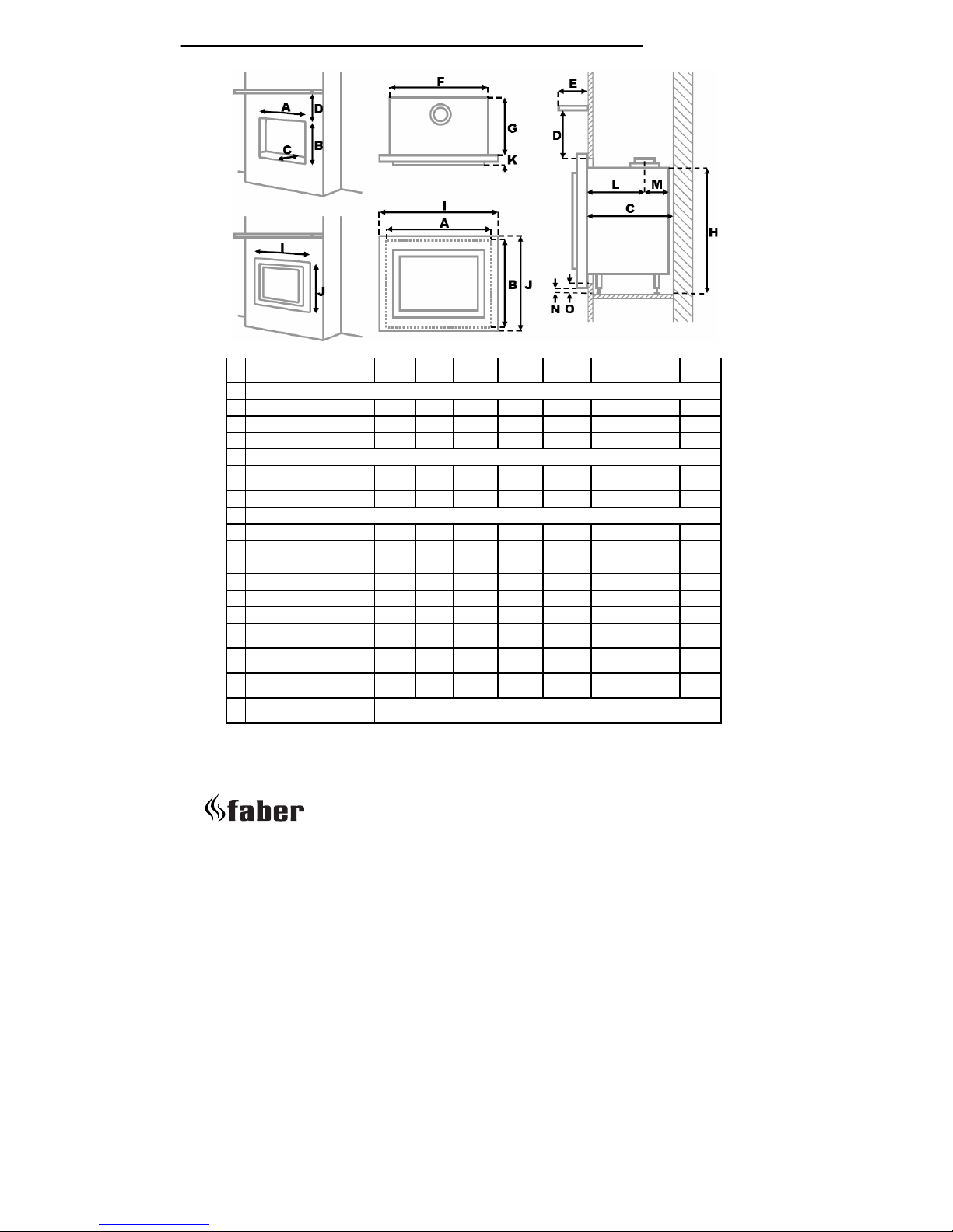
4.1 Builders opening and surround
The appliance can be installed in the following situations:
In a non-combustible fireplace or builders opening. This could be either
an existing builders opening or a new made prefab builders opening. For
the measurements, see figure 1 and index.
Although the appliance is tested for installation without a hearth, the
appliance must not stand on combustible materials or carpets. If the
appliance is placed on a combustible floor then a fibrelux or similar
heatproof board of 12 mm thickness should be placed under it. Any under
floor vents or openings within the builders opening should be sealed off.
Do not place the lintel, surround or marble stone directly onto the
appliance. If possible, apply a lintel made of cement or something similar.
Insulate the appliance with a ceramic blanket (25 mm). See also chapter
4: Installation instructions. Preferred choice for insulation is unbound
insulation wool (at 1000 °C gives no smell).
UK/IRL
> > > > 9
Builders opening (mm) Feeling Sense Silence Pure
(BF80S)
Whisper Spectra
Nova
Cadra
Nova
Misty
Builders opening (mm)
A Opening width
960 960 960 760 780 780 680 710
B Opening height
649 649 649 670 705 698 798 890
C Opening depth (min.)
385 385 385 397 430 430 430 370
Shelf dimensions
D Minimum height shelf
from top frame
350 350 350 350 350 350 350 350
E Depth shelf
150 150 150 150 150 150 150 150
Dimensions of the appliance (mm)
F Box width
880 880 880 750 750 750 650 698
G Box depth
369 366 369 397 397 375 375 338
H Box height
636 636 636 714 714 715 815 879
I Frame width
1064 1136 1064 795 815 794 694 740
J Frame height
678 750 678 795 720 703 803 905
K Frame thickness
47 57 20 35 16 30 30 144
L Position flue collar
measured from frame
255 255 255 255 257 235 235 196
M Position flue collar
measured from back
111 111 111 142 140 140 140 142
N Height underside foot to
underside frame
17 -20 17 -7 8 0 0 ?
O Height underside foot to
builders opening
≥ N (=dimensions in the row above)
tabel 1
*point A to C have a tolerance of -0 mm and +5 mm.

UK/IRL
10 < < < <
If the builders' opening is constructed out of non-combustible composition
board (Fibrelux) and you install the appliance without a mantel then:
• Ventilate the space above the appliance (min. 1000 mm2 ).
• Always fit the DC convection set.
• The plaster of the outside has to be resistant to a high temperature.
Use therefore the plaster materials especially made for this, to
prevent discoloring (min. 100 °C temperature resistant).
• Make sure the plaster dries well: 1 day for every millimetre plaster
applied, e.g. 4 mm plaster should dry for at least 4 days before the
appliance is used.
If the appliance is to be fitted against a wall with combustible cladding,
the cladding must be removed from the area covered by the surround.
The minimum height from the top surface of the fire to the underside of
any shelf made from wood or other combustible materials is as follows:
• For a shelf up to 150 mm deep – Minimum height = 350 mm (fig. 1).
• If the shelf depth is greater than 150 mm add 50 mm to the
upperclearance height for every 25 mm increase in shelf depth.
• Side clearance = Minimum distance from the side of the fire frame to
combustible material = 150 mm.
4.2 Flue requirements
• The appliance is of the type C11/C31. The appliance will need to be
supplied with the approved flue pipes and terminal, it is not possible
to supply your own.
• The minimum effective height of the flue system must be 0.5 or 1
meter, depending on the appliance.
• Terminal locations, through the wall and roof. See fig. 3.
Flue routing;
• a horizontal extension with elbows is allowed for a maximum of 6
meters (depending on the type and situation).
• vertical max. 12 meters.
UK/IRL
> > > > 11
Determine on the base of the table 2 and 3, depending on the type and
terminal position, if the desired situation is possible. To establish this you
will need to calculate:
• The effective height (this is the real difference in height between the
upper side of the appliance and the terminal).
• The total horizontal flue length, where:
à each elbow, which is in the horizontal area, counts for 2 meters.
à each 45°-bend, which is in the horizontal area, counts for 1 m
à elbows and bends at the transition of horizontal to vertically are
not to be counted.
à the wall mounted terminal counts for 1 meter.
Flue restrictor
If applicable, in the table is also stated the size of a flue restrictor. This
restrictor needs to be fitted in the combustion chamber when placing the
appliance (see chapter 4.2). Normally the smallest flue restrictor is fitted.
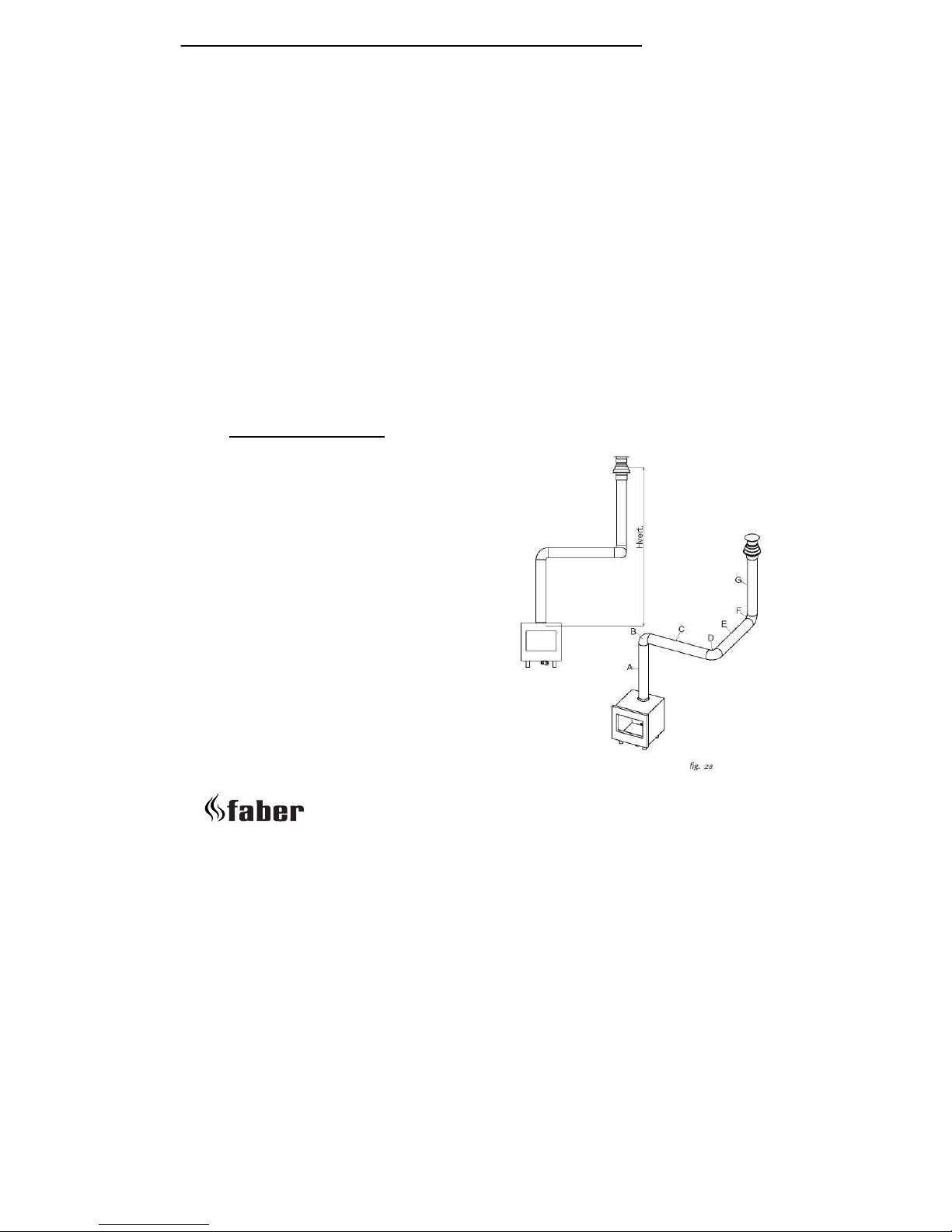
Example calculation 1:
Calculating horizontal extension fig. 2a:
Flue lenght C + E = 1m + 1m 2 m
Elbows D = 2m 2 m
Total horizontal extension 4 m
Measure or calculate effective height
(Hvert)
Flue lenght A 1 m
Roof mounted terinal 1 m
Total effective height 2 m
When calculating on basis of the
Widescreen table nr. 2: It is allowed.
Remove the flue restrictor!
When calculating on basis of the MV100
table nr. 3: Allowed but without flue
UK/IRL
12 < < < <
restrictor. Remove the flue restrictor!
When calculating on basis of theMV150 table nr. 4: Allowed but without
flue restrictor. Remove the flue restrictor!
When calculating on basis of the Roundscreen table nr. 5: Allowed but
without flue restrictor. Remove the flue restrictor!
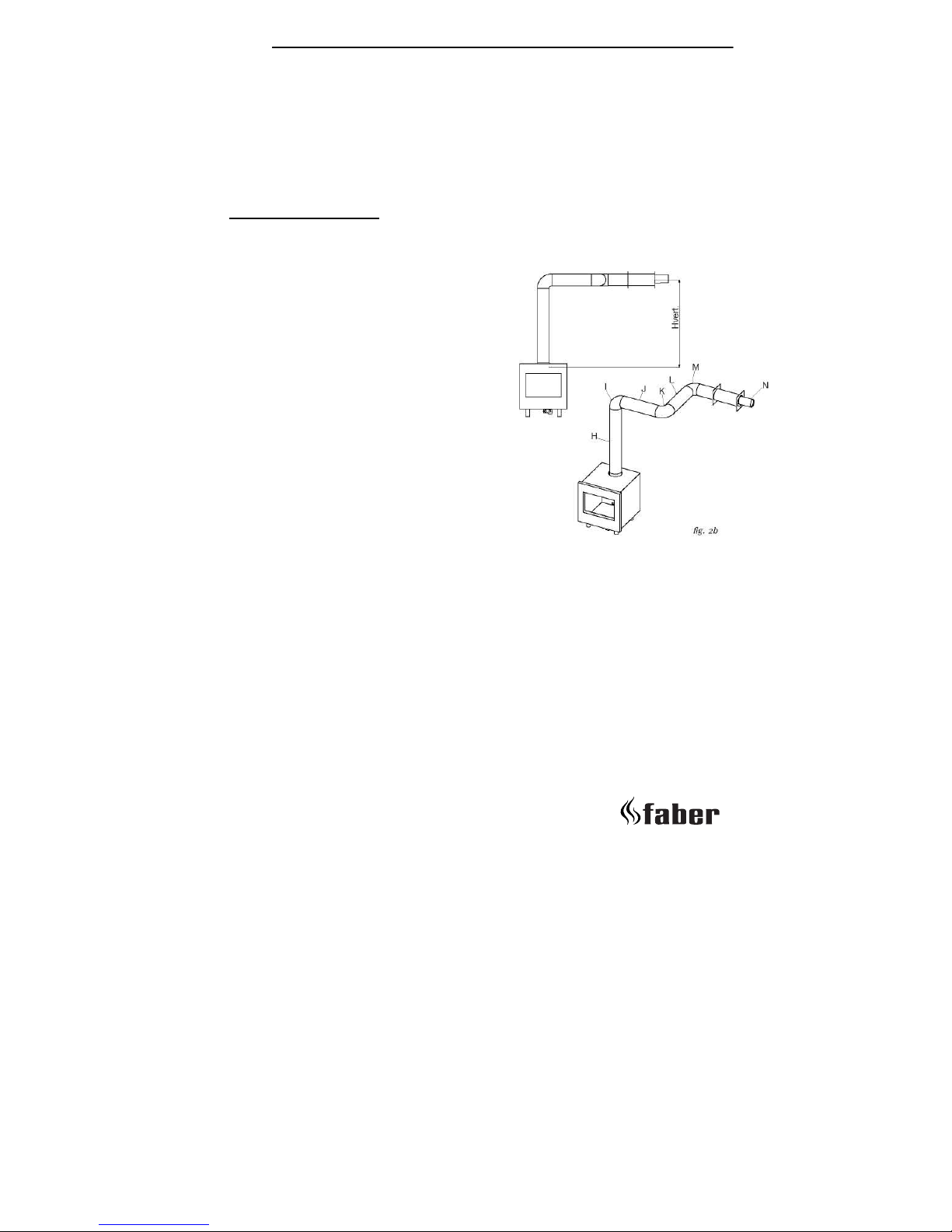
Example calculation 2
Calculation horizontal extension fig. 2b:
Flue lenght J + L = 0,5 + 0,5 1 m
Elbows K + M = 2m + 2m 4 m
Terminal 1 m
Total horizontal extension 6 m
Calculation effective height (Hvert)
Flue lenght H 1 m
When calculating on basis of the
Widescreen table nr. 2: Combination not
allowed.
When calculating on basis of the MV100
table nr. 3: Allowed but without flue
restrictor. Remove the flue restrictor!
When calculating on basis of the MV150
table nr. 4: Combination not allowed.
When calculating on basis of the Roundscreen table nr. 5: Combination
not allowed.
4.3 Tables for determining the right flue restrictor
Calculate the total horizontal- and vertical length of the flue, according
to the calculations displayed above. Determine according to tables 2, 3, 4
and 5 on the following pages the right flue restrictor size. When meeting
an X, and when the values are outside the table, the combination is not
allowed. Normally the 30 mm flue restrictor is preinstalled.
UK/IRL
> > > > 13
0123456
0XXXXXXX
100XXXXX
1,50000XXX
2303000000
3 45453030 0 0 0
4 4545303030 0 0
5 505045303030 0
6 505045303030 0
7 606050454530 X
8 6060605050 X X
9 65656060 X X X
10656565XXXX
116565XXXXX
1265XXXXXX
0123456
0XXXXXXX
130000000/X*
2303000000
3 454530 0 0 0 0
4 454530 0 0 0 0
5 5050454530 0 0
6 5050454530 0 0
7 606060505045 X
8 6060606050 X X
9 65656060 X X X
10656565XXXX
116565XXXXX
1265XXXXXX
Table 2: Widescreen (Feeling, Silence, Sense)
Vertical length in m
Table 3: MV200 (Pure (BF80S), Spectra Nova, Whisper)
Horizontal length in m
Vertical length in m
The numbers in the table
represent the width in mm of the
flue restrictor
X Combination NOT allowed
0 remove flue restrictor
The numbers in the table
represent the width in mm of the
flue restrictor
X Combination NOT allowed
0 remove flue restrictor
Horizontal length in m
UK/IRL
14 < < < <
0123456
0XXXXXXX
0,5X0XXXXX
1X3000000
2403000000
3 404030 0 0 0 0
4 50404030 0 0 0
5 505040403030 0
6 505050404030 0
7 605050404040 X
8 6060505050 X X
9 60606050 X X X
10656060XXXX
116565XXXXX
1265XXXXXX
0123456
0XXXXXXX
0,5X0XXXXX
1X3000000
0,5403000000
2403000000
3404000000
4 50404030 0 0 0
5 505040403030 0
6 505050404030 0
7 605050404040 X
8 6060505050 X X
9 60606050 X X X
10656060XXXX
116565XXXXX
1265XXXXXX
Tabel 4: binnenwerk MV150 (Cadra Nova)
Vertical length in m
Tabel 5: binnenwerk Roundscreen (Misty)
Vertical length in m
Horizontal length in m
Horizontal length in m
The numbers in the table
represent the width in mm of the
flue restrictor
X Combination NOT allowed
0 remove flue restrictor
The numbers in the table
represent the width in mm of the
flue restrictor
X Combination NOT allowed
0 remove flue restrictor

UK/IRL
> > > > 15
4.3.1 Terminal position
Verify if the required terminal position meets the local installation
regulations regarding disturbance, good functioning and ventilation. (Also
see: safety requirements).
Note:
The terminal must be located so that the outlet is not obstructed. If the
flue terminal is located within 2 meters of a footway, path or where
people could come into contact with it then a suitable terminal guard
must be fitted.
Terminals located close to shared walkways, footpaths etc. could be
subject to legal constraints and this should be pointed out to the
customer before installation. If in any doubt about flue location advice
should be sought from local building control, or if appliancerelated, from
the manufacturer including wherever possible a dimensioned sketch.
Avoid locating the terminal in close proximity to plastic materials such as
gutters or other combustibles. If this is unavoidable then a suitable
deflector should be made.
Some important requirements for a good functioning are:
The wall-mounted terminal has to be at least 0,5 m off:
à Corners of the building.
à Below eaves.
à Balcony's etc. unless the duct is dragged to the front side of the
overhanging part.
The roof mounted terminal has to be at a distance of at least 0.5 meters
of the sides of the roof, excluded the ridge.
UK/IRL
16 < < < <
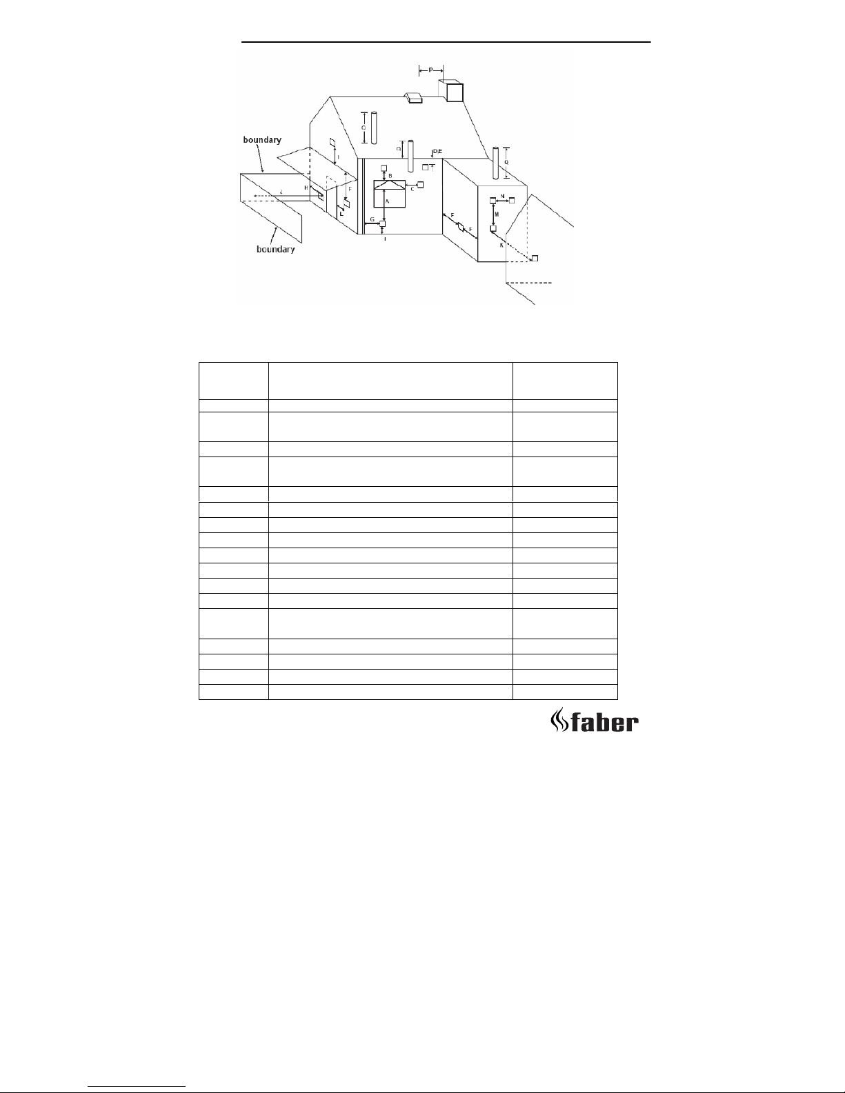
Dimension Terminal position
(kW input 7.5 kW expressed in net)
Balanced flue
room sealed
Natural Draught
A Direct below an opening, airbrick, opening
windows, etc.
300 mm
B Above an opening, airbrick, opening window, etc. 300 mm
C Horizontally to an opening, airbrick, opening
window, etc.
300 mm
D Below gutters, soil pipes or drain pipes 500 mm
E Below eaves 500 mm
F Below balconies or cat port roof 600 mm
G From a vertical drain pipe or soil pipe 300 mm
H Dfrom an internal or external corner 600 mm
I Above ground roof or balcony level 300 mm
J From a surface facing the terminal 600 mm
K From a terminal facing a terminal 600 mm
L From an opening in the carport (e.g. window) into
the dwelling
1200 mm
M Vertically from a terminal on the same wall 1500 mm
N Horizontally from a terminal on the same wall 300 mm
P From a vertical structure on the roof 600 mm
Q Above intersection with roof 500 mm
Flue terminal
Fig. 3
Tabel 6
UK/IRL
> > > > 17
4.3.2 Using an existing chimney as air inlet
You can connect the appliance onto an existing chimney. The existing
chimney then functions as air supply, where a flexible stainless steelliner
(to BS715) of 100 mm performs the flue function.
Requirements:
• Any existing chimney used as an air supply must only service this
appliance.
• A chimney that has previously been used for solid fuel must be swept
before use.
• The existing chimney needs to be airtight.
• The existing chimney needs to have an opening of min. 150 x 150 mm.
• The chimney needs to be intact and well looked after.
• Use the adjustable roof-mounted-terminal especially made for this,
and the chimney connection set.
• The minimum distance between two terminals should be at least 450
mm.
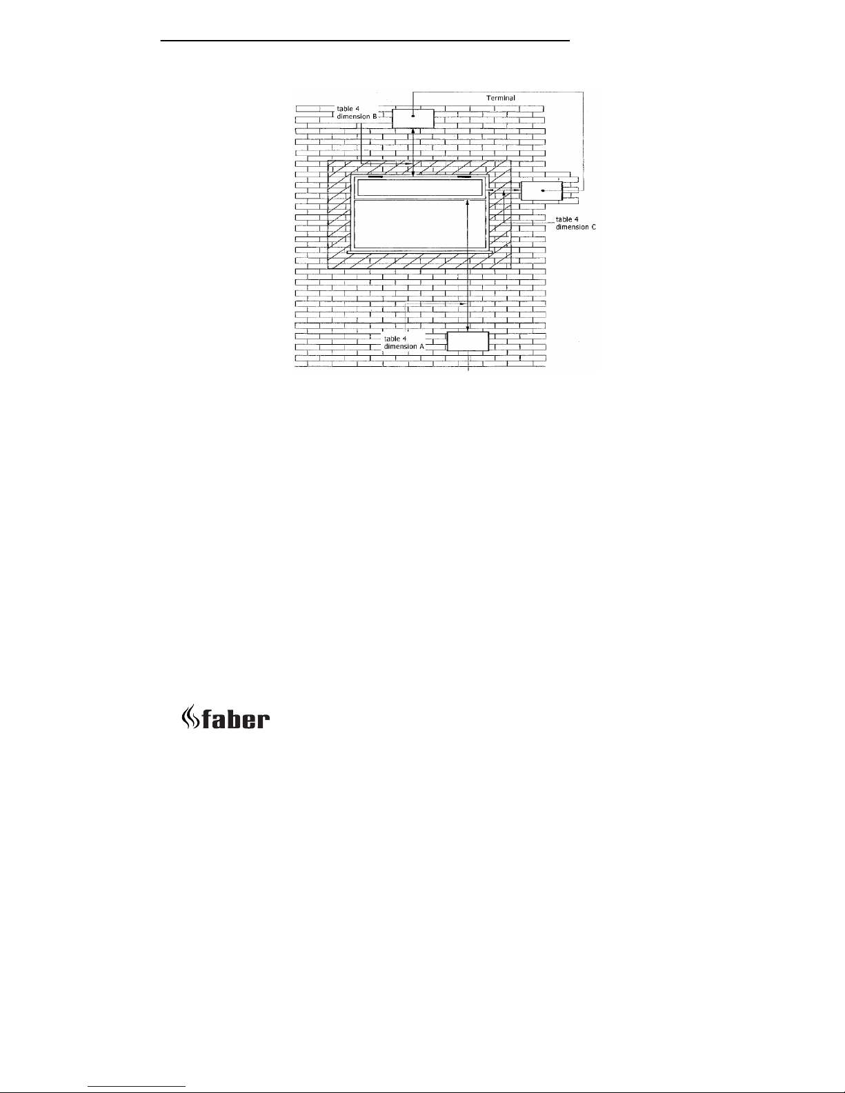
Example of how terminal position is measured
Fig. 4
 Loading...