

Faber SILVA, CADRA, PRISMA, SPECTRA FRONT, SPECTRA PANORAMA Installation Manual And User's Manual
installation guide and user manual
room-sealed built-in gas-fireplace
40 010 516
01 45
SILVA
CADRA
PRISMA
SPECTRA FRONT
SPECTRA PANORAMA
Saturnus 8 NL-8448 CC Heerenveen
Postbus 219 NL-8440 AE Heerenveen
T. +31(0)513 656500
F. +31(0)513 656501
“Flat Fibre Burner Technology”
For use with natural gas only

1
CONTENTS
1. INTRODUCTION 2
2. SAFETY INSTRUCTIONS 3
3. INSTALLATION REQUIREMENTS 5
3.1 Builders opening and surround 5
3.2 Requirements outlet and exhaust 8
4. INSTALLATION-INSTRUCTIONS 16
4.1 Gas connection 16
4.2 Preparation of the appliance 16
4.3 Fitting the firebox 19
4.4 Placing of the wood set 20
5. INSTALLATION OF THE FLUE 22
5.1 Connection of the flue 22
5.2 Placing through existing chimney 23
5.3 Remote control 25
6. COMMISIONING 27
6.1 Check pilot ignition 27
6.2 Functional burner check 27
6.3 Functional balanced flue check 28
6.2 Check reference pressure 28
7. HANDING OVER 29
8. SERVICING 30
8.1 Routine annual servicing 30
UUSSEERR GGUUIIDDEE
38
9. SAFETY INSTRUCTIONS FOR THE USER 39
10. CONTROLING THE APPLIANCE 41
11. CLEANING AND SERVICE INSTRUCTIONS 47
12. DISPOSAL OF THE PACKAGING AND THE APPLIANCE 48
INDEX 1 LIST OF SPARE PARTS 35
INDEX 2 TECHNICAL DATA 36
UK/IRL

UK/IRL
2
UK/IRL
3
1. INTRODUCTION
NNoottee:: tthheessee iinnssttrruuccttiioonnss sshhoouulldd bbee rreeaadd ccaarreeffuullllyy aanndd rreettaaiinneedd ffoorr
ffuuttuurree rreeffeerreennccee..
PPlleeaassee lleeaavvee tthheessee iinnssttrruuccttiioonnss wwiitthh tthhee uusseerr..
This guide is concerning the following types of appliances:
Silva
Cadra
Prisma
Spectra
Spectra Panorama
Special features:
- Realistic flame and glow effect because of the "flat fibre burner"
technology.
- Room sealed room appliance, inlet and outlet are led to the outside
using a natural draught concentric pipe system (100 mm/150 mm)
(no power fan required). No additional ventilation required.
- Air supply and flue-gases go to outside atmosphere through wall or
roof. A maximum horizontal extension of 6 meters is possible.
- Remote Control option on all appliances.
- Meets the essential requirements of the European Gas Appliance
Directive (GAD) and carries the CE mark.
2. SAFETY AND GENERAL
INFORMATION
Before installation, ensure that the local distribution conditions
(identification of the type of gas and pressure) and the adjustment of
the appliance are compatible.
This gas appliance is factory set and shall not be adjusted by the
installer.
This appliance does not contain any component manufactured from
asbestos or any asbestos related products.
The pilot and flame sensing device fitted to this fire is also a safety
device. If for any reason any part of the pilot assembly is to be
replaced the entire assembly including the pilot burner, thermocouple,
electrode and injector must be exchanged complete for a pilot assembly
from the original manufacturer only.
Ventilation
This appliance is room-sealed and doesn't require purpose provided
ventilation.
2.1 General safety
It is the law in the UK that
aallll
gas appliances, are installed by a
competent person in accordance with the Gas Safety (Installation and
Use) Regulations (as amended), the relevant British Standards for
Installation work, Building Regulations, Codes of Practice and the
manufacturers instructions.
The installation should also be carried out in accordance with the
following where relevant:
BS5871 Part1 BS5440 Parts 1 & 2 BS1251.
Building Regulations Document J (as applicable).

UK/IRL
5
UK/IRL
4
Building Regulations and Standards issued as relevant by the
Department of the Environment or the Scottish Development
Department.
In the Republic of Ireland installation should be carried out in
accordance with IS813, ICP3, IS327, Building Regulations, Codes of
Practice, the manufacturers instructions and any other rules in force.
Failure to comply with the above could leave the installer liable to
prosecution and invalidate the appliance warranty.
Safety instructions for the user: see chapter 9.
3. INSTALLATION REQUIREMENTS
Note:
Since the appliance is a source of heat, circulation of air occurs.
Therefore it is of importance that you do not use the appliance
shortly after a renovation of the home. Because of the natural
circulation of air, moist and volatile components from paint, building
materials, carpet etc. will be attracted. These components can settle
themselves down onto cold surfaces in the form of soot.
As on all heat producing appliances, soft furnishings such as blown
vinyl wallpaper placed too near to the appliance may become
scorched or discoloured. This should be born in mind when installing
the appliance.
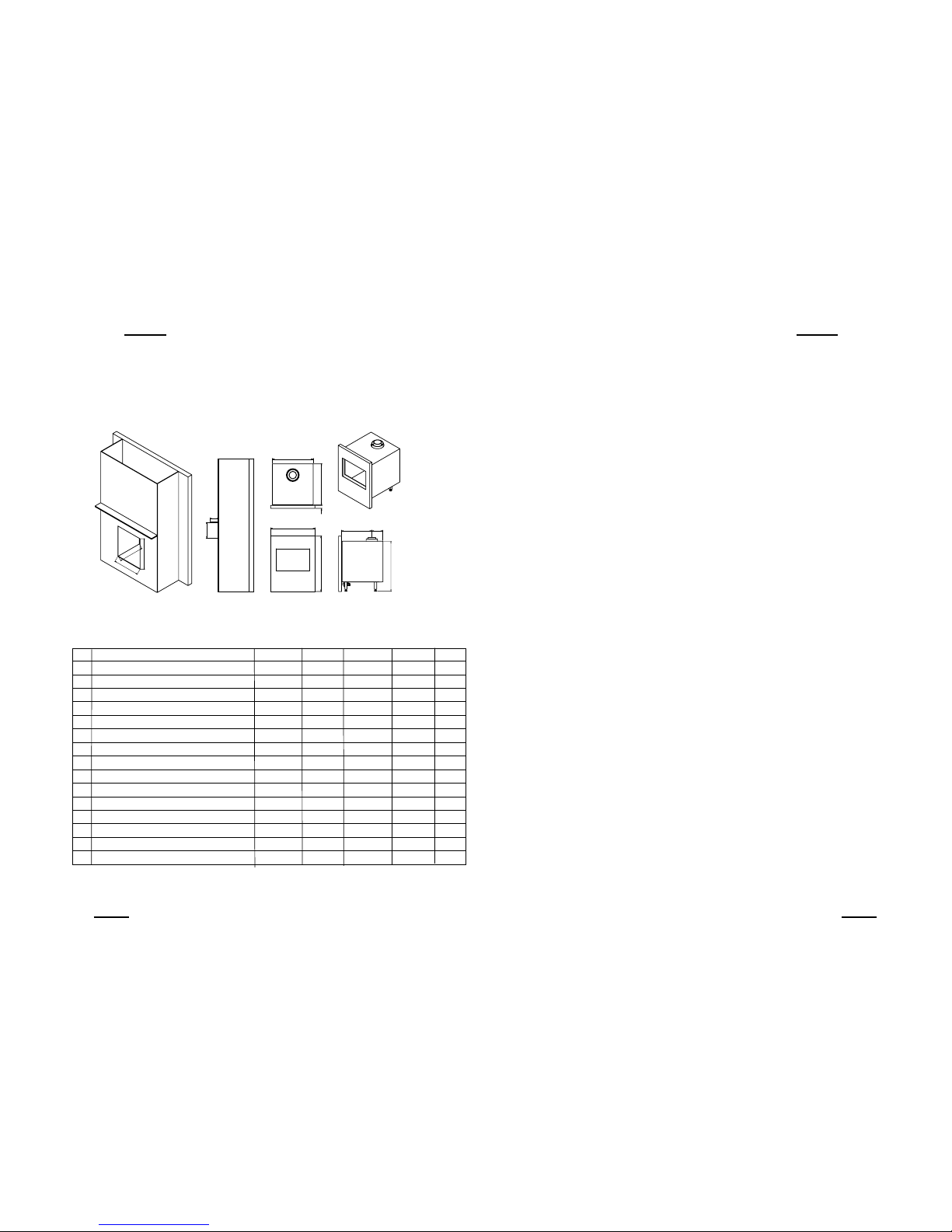
3.1 Builders opening and surround
The appliance can be installed in the following situations:
In a non-combustible fireplace or builders opening. This could be either
an existing builders opening or a new made prefab builders opening.
For the measurements, see figure 1 and index.
Although the appliance is tested for installation without a hearth, the
appliance must not stand on combustible materials or carpets. If the
appliance is placed on a combustible floor then a fibrelux or similar
heatproof board of 12 mm thickness should be placed under it. Any
under floor vents or openings within the builders opening should be
sealed off.
Do not place the lintel, surround or marble stone directly onto the
appliance. If possible, apply a lintel made of cement or something
similar.
Isolate the appliance with a ceramic blanket (25 mm). See also
chapter 4: Installation instructions.
Preferred choice for insulation is unbound insulation wool (at
1000 °C gives no smell).
UK/IRL
7
UK/IRL
6
3.1 Builders opening and surround (continuing)
If the builders' opening is constructed out of non-combustible
composition board (Fibrelux) and you install the appliance without a
mantel then:
- Ventilate the space above the appliance (min. 1000 mm
2
).
- Always fit the DC convection set.
- The plaster of the outside has to be resistant to a high
temperature. Use therefore the plaster materials especially made for
this, to prevent discoloring (min. 100 °C temperature resistant).
If the appliance is to be fitted against a wall with combustible
cladding, the cladding must be removed from the area covered by the
surround.
The minimum height from the top surface of the fire to the underside
of any shelf made from wood or other combustible materials is as
follows:
- For a shelf up to 150 mm deep – Minimum height = 350 mm
(fig. 1).
- If the shelf depth is greater than 150 mm add 50 mm to the upper-
clearance height for every 25 mm increase in shelf depth.
- Side clearance = Minimum distance from the side of the fire frame
to combustible material = 150 mm.
fig. 1
table 1
BBuuiillddeerrss ooppeenniinngg ((mmmm)) SSppeeccttrraa CCaaddrraa PPaannoorraammaa PPrriissmmaa SSiillvvaa
A Opening width 780 680 810 710 600
B Opening height 705 805 710 710 715
C Opening depth (min.) 430 430 430 430 350
SShheellff ddiimmeennssiioonnss ((ccoommbbuussttiibbllee))
D Min. height shelf from top frame 350 350 350 350 350
E Depth shelf max. 150 150 150 150 150
DDiimmeennssiioonnss ((mmmm))
F Box width 752 652 752 652 575
G Box depth 395 395 395 395 309
H Box height 714 814 714 714 693
I Frame width 790 690 875 775 629
J Frame height 720 820 732 732 727
K Frame thickness 22.5 22.5 122 124 15
L Position flue (behind frame) 256.5 256.5 255 255 190
M Position flue (from the back side box) 140 140 140 140 119
L
M
F
I
C
B
A
J
E
D
G
K
H

UK/IRL
9
UK/IRL
8
3.2 Flue requirements
The appliance is of the type C11/C31. The appliance will need to be
supplied with the approved flue pipes and terminal, it is not possible to
supply your own.
The minimum effective height of the flue system must be 1 m.
Terminal locations, through the wall as well as through the roof. See
figure 3.
Flue routing;
- a horizontal extension with elbows is allowed for a maximum of 6
meter (depending on the type and situation).
- vertical max. 12 meter.
Determine on the base of the table 2 and 3, depending on the type
and terminal position, if the desired situation is possible.
To establish this you will need to calculate:
-The effective height (this is the real difference in height between the
upper side of the appliance and the terminal).
- The total horizontal extension. This is the total horizontal flue length
where:
• each elbow, which is in the horizontal area, counts for 2 meters.
• each 45-degree bend, which is in the horizontal area, counts for 1
meter.
• elbows and bends at the transition of horizontal to vertically are
not to be counted.
• the wall mounted terminal counts for 1 meter.
FFlluuee rreessttrriiccttoorr
If applicable, in the table is also stated the size of a flue restrictor.
This restrictor needs to be fitted in the combustion chamber when
placing the appliance ( see chapter 4.2). Normally the smallest flue
restrictor is fitted.
UK/IRL
11
01 2 3 4 56
0
XX X X X XX
XXXXXX
XXXXX
XXXX
XXX
XX
X
000XX
00X
1 0 0
1,5 0 0 0 0
2 52.5 45/52.5 0 0 0 0 0
3 52.5 45/52.5
45/52.5
0 0 0 0
4 52.5 45/52.5
45/52.5
45/52.5 0 0 0
5 52.5 45/52.5
45/52.5
45/52.5 45/52.5 0 0
6 52.5 45/52.5
45/52.5
45/52.5 45/52.5 0 0
7 52.5 45/52.5
45/52.5
45/52.5 45/52.5 45/52.5
8 52.5 45/52.5
45/52.5
45/52.5 45/52.5
9 52.5 45/52.5
45/52.5
45/52.5
10 52.5 45/52.5
45/52.5
11 52.5 45/52.5
12 52.5
Horizontal extension
Effective height
Table Spectra, Spectra Panorama, Prisma and Cadra
Determine according to the table 2 the right total horizontal- and vertical length.
When meeting an X, and when the values are outside the table, the combination
is not allowed.
Table Silva
Determine according to the table 3 the right total horizontal- and vertical length.
When meeting an X, and when the values are outside the table, the combination
is not allowed. The value 45/52.5 means place a flue restrictor of 52.5mm when
using a roof mount terminal or 45 mm when you installing a wall mount terminal.
NNoorr mmaallllyy tthhee 4455 mmmm fflluuee rreessttrriiccttoorr iiss pprreeiinnssttaalllleedd..
0123456
0
XXX XXXX
XXX XXX
XXXXX
XXXX
XXX
XX
X
1 0 0 0 0
0
0
0
2 0 0 0 0 0 0 0
3 0 0 0 0 0 0 0
4 0 0 0 0 0 0 0
5 0 0 0 0
0
0 0
6 0 0 0 0
0
0 0
7 0 0 0 0 0
0
8 0 0 0 0 0
9 0 0 0 0
10 0
0 0
11 0 0
12 0
Horizontal extension
Effective height
table 2
table 3
UK/IRL
10
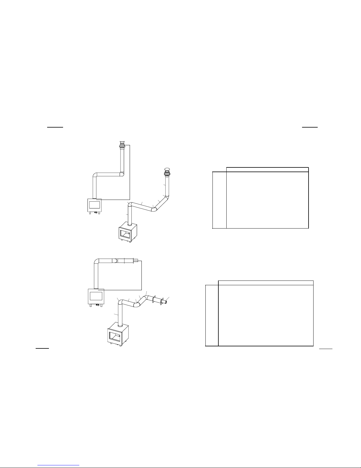
fig. 2a
Hvert.
N
M
L
K
J
I
H
fig. 2b
Hvert.
A
F
G
E
D
C
B
Example calculation 1
Calculati0n horizontal extension fig. 2a:
Flue lenght C + E = 1m + 1m 2 m
Elbows D = 2m 2 m
Total horizontal extension 4 m
Measure or calculate ef fective height
(Hvert)
Flue lenght A 1 m
Roof mounted terminal 1 m
Total effective height 2 m
When calculating on basis of the
Spectra table Nr. 2:
It is allowed.
When calculating on basis of the Silva
table Nr. 3:
Allowed but without flue restrictor.
Remove the flue restrictor!
Example calculation 2
Calculati0n horizontal extension fig. 2b:
Flue lenght J + L = 0,5 + 0,5 1 m
Elbows K + M = 2m + 2m 4 m
Terminal 1 m
Total horizontal extension 6 m
Vertical
Flue lenght H 1 m
When calculating on basis of the
Spectra table Nr. 2:
It is allowed.
When calculating on basis of the Silva
table Nr. 3:
Combination not allowed.
UK/IRL
13
UK/IRL
12
3.2 Flue requirements (continuing)
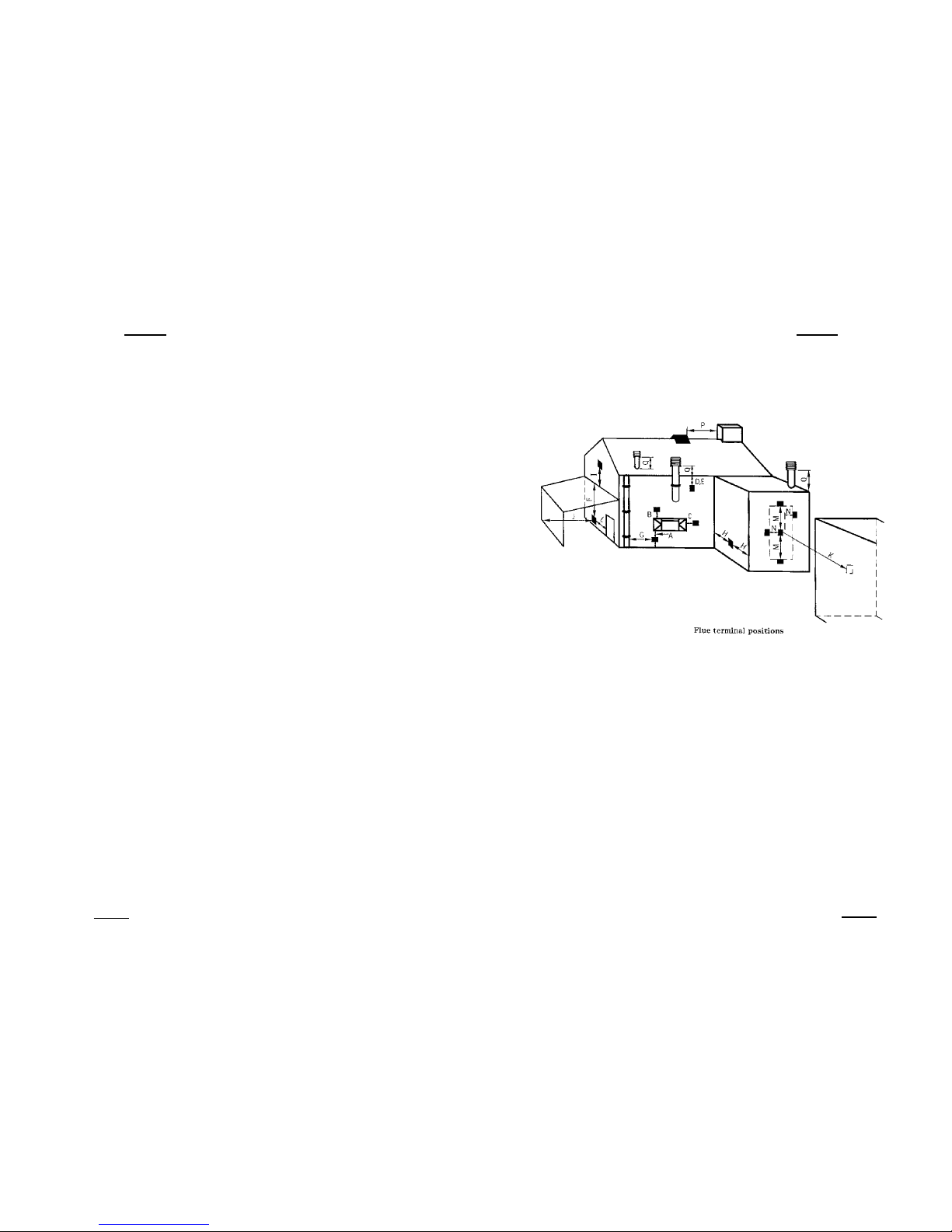
3.2.1 Terminal position
Verify if the required terminal position meets the local installation
regulations regarding disturbance, good functioning and ventilation.
(Also see: safety requirements).
NNoottee::
The terminal must be located so that the outlet is not obstructed. If
the flue terminal is located within 2 meters of a footway, path or
where people could come into contact with it then a suitable
terminal guard must be fitted.
Terminals located close to shared walkways, footpaths etc. could be
subject to legal constraints and this should be pointed out to the
customer before installation. If in any doubt about flue location
advice should be sought from local building control, or if appliancerelated, from the manufacturer including wherever possible a
dimensioned sketch.
Avoid locating the terminal in close proximity to plastic materials
such as gutters or other combustibles. If this is unavoidable then a
suitable deflector should be made.
Some important requirements for a good functioning are:
The wall-mounted terminal has to be at a distance of at least 0,5
meters off:
- Corners of the building.
- Below eaves.
- Balcony's etc. unless the duct is dragged to the front side of the
overhanging part.
The roof mounted terminal has to be at a distance of at least 0,5
meters of the sides of the roof, excluded the ridge.
Flue terminal positions
fig. 3
 Loading...