

Faber NL-8448 CC Heerenveen, Postbus 219, Saturnus 8, NL-8440 AE Heerenveen Installation And Operating Instructions Manual
Page 1
installation and operating instructions
electrical ambience heating
KOLDING
ELECTRIC
Saturnus 8 NL-8448 CC Heerenveen
Postbus 219 NL-8440 AE Heerenveen
T. +31(0)513 656500
F. +31(0)513 656501
40 010 5XX
0138
Page 2

GB GB
GB 1
TABLE OF CONTENTS
1. FOREWORD GB 2
2. INTRODUCTION GB 3
3. SAFETY PRECAUTIONS GB 4
4. INSTALLATION GB 6
4.1 Dimensions
GB 6
4.2 Location and Minimum Free Space
GB 6
5. OPERATION GB 7
5.1 Operation
GB 7
5.2 Flame effect
GB 7
5.3 Heating unit
GB 7
5.4 Thermostat operation
GB 8
5.5 Thermal safety cut-out
GB 8
6. CLEANING AND MAINTENANCE GB 9
6.1 Cleaning
GB 9
6.2 Lamp replacement
GB 9
Page 3

GB
GB 3
GB
GB 2
2. INTRODUCTION
This instruction manual gives you information about the design,
operation and maintenance of your fire, as well as safety
precautions and environmental recommendations.
As you read this manual, you will quickly learn how to operate your
fire. You will also find information about the safety and
maintenance of the equipment.
Read the manual carefully before using your hearth and then keep
the manual in a safe place.
1. FOREWORD
This fire incorporates a flame effect which can be used with or
without heating, so that comforting effect may be enjoyed at any
time of the year. The flame effect is provided by low wattage
motors and three 40 Watt lamps. Using the flame effect on its own,
therefore, requires little electricity.
The controls are concealed behind the 'ashpan' flap, control cover.
A choice of 1000 W or 2000 W thermostatically controlled heat
output is provided by the fan heater, which is concealed behind the
top grille.
Kolding Electric is designed to be free standing and are normally
positioned against a wall.
This appliance complies with the CE directives.
Page 4

GB
GB 5
GB
GB 4
- Do not use the appliance if the stove or connecting cable become
damaged in any way. In this event, the appliance should first be
checked by an approved installer.
- The stove is only suitable for use in dry areas. Do not install the
stove in humid areas, such as a bathroom, scullery or cellar.
- Lay the connecting cable beneath a carpet or rug, in such a manner
that people cannot trip over it.
- Do not locate the heater immediately below a fixed socket outlet
or connection box.
- Do not cover the heater. Do not place material or garments on the
heater, or obstruct the air circulation around the heater, for
instance by curtains or furnitue, as this could cause overheating
and a fire risk
.
- Do not use this heater in series with a thermal control, a
programme controller, a timer or any other device that switches or
the heater automatically, since a fire risk exists when the heater
is accidentally covered or displaced.
- In the event of a fault unplug the heater.
- Remove the connection plug from the socket before cleaning or
carrying out any maintenance of the stove. The stove should also
be disconnected from the power source before any repairs are
carried out.
- Altough this heater complies with safety standards, we do not
recommend its use on deep pile carpets or on long hair type of
rugs.
3. SAFETY PRECAUTIONS
Ensure that all packaging items are removed (read any warning
labels carefully).
Please keep this manual for further reference.
Retain all packaging untill installation is complete.
This product complies with current safety standards. However, as with
any other electrical appliance, the product should be used with due
care and attention to minimise the inherent safety risks.
- Please read this manual carefully before using the stove for the first
time.
- The stove becomes hot during operation. Ensure that furniture,
curtains and other flammable materials are kept at least 100 cm
away from the stove.
- Do not leave young children or the infirm unsupervised in the
vicinity of the heater.
- Connect the stove by means of an earthed electrical socket that
complies with the applicable standards.
- This appliance is suitable for use with a 230 V, 50 Hz connection,
and has a maximum electrical capacity of 1800 W.
- The appliance must be positioned so that the plug is accessible.
- Unplug the heater when not required for long periods.
Page 5
GB
GB 7
GB
GB 6
5. OPERATION
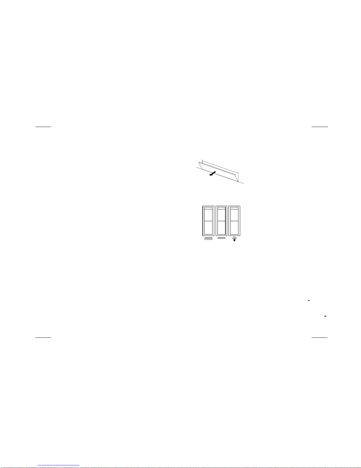
5.1 Operation
The controls are located behind the hinged
'ashpan' flap, control cover (fig. 1).
5.2 Flame ef fect
Press L switch to the 'ON' position (a switch is in
the "ON" position when the red indicator mark on
the switch is visible). The flame effect will now
operate.
5.3
5.3 Heating unit
You have a choice of low heat 900 W or high heat 1800 W output.
Both settings have thermostat temperature control. In order to
operate the heating, switch L must be in the 'ON' position (see fig.
2).
Low Heat Setting
With switch L in the 'ON' position, press switch ' ' to 'ON'.
High Heat Setting
With switches L and ' ' in the 'ON' position, press Switch ' ' to
'ON'. The 1800 W heat output is controlled by the thermostat, which
should be set to maximum (see 'thermostat operation').
4. INSTALLATION
4.1 Dimensions
W x H x D : 620 x 705 x 470 mm
4.2 Location and minimum free space
The stove should be placed at least 10 cm away from walls that are
not heat-resistant.
The electrical plug should only be connected to the power supply
by means of a Faber International earthed socket.
fig. 1
fig. 2
Page 6

GB
GB 8
5.4 Thermostat operation
The thermostat controls the heat output according to the room
temperature. This ensures that the heater will not produce heat
unnecessary when the room is warm.
To set the temperature you require, turn the thermostat knob fully
clockwise to 'max' position. When the room is warm enough, turn
the knob back slowly until the thermostat just clicks off. The
heater will now maintain your selected temperature (fig. 3).
Note: Once the thermostat has switched the appliance off it may
take some time before the heater comes back on. This does not
mean that the appliance is faulty.
5.5 Thermal safety cut-out
A thermal safety cut-out is incorporated in the heater to prevent
damage due to overheating.This can happen if the heat outlet was
restricted in any way. The heater will switch on once the
obstruction has been removed and the heater has cooled.
NNoottee
: If the cut-out continues to operate intermittently, the heater
should be switched off and a service agent contacted.
m
i
n
m
a
x
e
c
o
n
fig. 3
6. CLEANING AND MAINTENANCE
Always disconnect from the power supply before attempting any
maintenance.
6.1 Cleaning
Before commencing cleaning, unplug the heater and allow it to
cool.
The surface of the heater should be given an occasional wipe over
with a soft damp cloth. Do not use detergents abrasive cleaning
powder or polish on the body of the heater. The glass screen
should be cleaned carefully with a chamois leather. Do not use
proprietary glass cleaners
.
6.2 Lamp replacement
To gain acces to the lamps open the ashpan
flap control cover. Lift the flame effect window
upwards and remove.
Remove the fuel assembly by lifting slightly and
sliding out (fig. 4).
Unscrew the defective lamp anti-clockwise (fig.
5).
Replace with a 230 V, 40 W E14 SES lamp, do
not over tighten.
Refit fuel assembly and slide up against the
inner glass. Replace the flame effect window.
Warning:
fig. 4
fig. 5
GB 9
GB
 Loading...