

Page 1

Instructions Manual
Manuel d’Instructions
Bedienungsanleitung
Manual de instrucciones
Εγχειρίδιο οδηγιών
Руководство по эксплуатации
ﺐﻴآﺮﺘﻟا ﻞﻴﻟ
د
Page 2

EN
2
2
Instructions Manual
INDEX
RECOMMENDATIONS AND SUGGESTIONS......................................................................................................................9
CHARACTERISTICS............................................................................................................................................................10
INSTALLATION ....................................................................................................................................................................12
USE.......................................................................................................................................................................................15
MAINTENANCE....................................................................................................................................................................17
Page 3

FR
3
3
Manuel d’Instructions
SOMMAIRE
CONSEILS ET SUGGESTIONS ..........................................................................................................................................20
CARACTERISTIQUES.........................................................................................................................................................21
INSTALLATION ....................................................................................................................................................................23
UTILISATION........................................................................................................................................................................26
ENTRETIEN..........................................................................................................................................................................28
Page 4

DE
4
4
Bedienungsanleitung
INHALTSVERZEICHNIS
EMPFEHLUNGEN UND HINWEISE....................................................................................................................................31
CHARAKTERISTIKEN..........................................................................................................................................................32
MONTAGE............................................................................................................................................................................34
BEDIENUNG.........................................................................................................................................................................37
WARTUNG............................................................................................................................................................................39
Page 5

ES
5
5
Manual de instrucciones
ÍNDICE
CONSEJOS Y SUGERENCIAS...........................................................................................................................................42
CARACTERÍSTICAS............................................................................................................................................................43
INSTALACIÓN......................................................................................................................................................................45
USO......................................................................................................................................................................................48
MANTENIMIENTO................................................................................................................................................................50
Page 6

GR
6
6
Εγχειρίδιο οδηγιών
ΠΕΡΙΕΧΟΜΕΝΑ
ΣΥΜΒΟΥΛΕΣ ΚΑΙ ΣΥΣΤΑΣΕΙΣ.............................................................................................................................................53
ΧΑΡΑΚΤΗΡΙΣΤΙΚΑ................................................................................................................................................................54
ΕΓΚΑΤΑΣΤΑΣΗ.....................................................................................................................................................................56
ΧΡΗΣΗ ..................................................................................................................................................................................59
ΣΥΝΤΗΡΗΣΗ ........................................................................................................................................................................61
Page 7

RU
7
7
Руководство по эксплуатации
УКАЗАТЕЛЬ
СОВЕТЫ И РЕКОМЕНДАЦИИ...........................................................................................................................................64
ХАРАКТЕРИСТИКИ.............................................................................................................................................................65
УСТАНОВКА........................................................................................................................................................................67
ЭКСПЛУАТАЦИЯ.................................................................................................................................................................70
УХОД ....................................................................................................................................................................................72
Page 8

SA
8
8
ﺐﻴآﺮﺘﻟا ﻞﻴﻟد
ﻔﻟا سﺮﻬ
تﺎﺣاﺮﺘﻗا و تادﺎﺷرا........................................................................................................................................75
ﺺﺋﺎﺼﺨﻟا ....................................................................................................................................................76
ﺐﻴآﺮﺘﻟا .......................................................................................................................................................78
ماﺪﺨﺘﺳﻻا .....................................................................................................................................................81
ﺔﻧﺎﻴﺼﻟا ﺔﻴﻠﻤﻋ ................................................................................................................................................84
Page 9

EN
9
9
RECOMMENDATIONS AND SUGGESTIONS
The Instructions for Use apply to seve ral versions of this appliance. Ac-
cordingly, you may find descripti ons of individual features th at do not apply to your specific appliance.
INSTALLATION
• The manufacturer will not be held liable for any dam ages resulting from
incorrect or improper installation.
• Check that the mains voltage corresponds to th at indicated on the rating
plate fixed to the inside of the hood.
• For Class I appliances, check that th e domestic power s upply guarante es
adequate earthing.
• Connect the extractor to the exh aust flue through a pipe of minim um diameter 120 mm. The route of the flue must be as short as possible.
• Do not connect the extractor hood to exhaust ducts carrying combustion
fumes (boilers, fireplaces, etc.).
• If the extract or is used in conjunction with non-electrical appli ances (e.g.
gas burning appliances ), a sufficient degree of aeration must be gu aranteed in the room in order to prevent the backflow of exhaust gas. The
kitchen must have an opening commun icating direc tly with the open air in
order to guarantee the entry of clean air.
USE
• The extractor hood has been designed exclusively for domestic use to
eliminate kitchen smells.
• Never use the hood for purposes other than for which it has ben designed.
• Never leave high naked flames under the hood when it is in operation.
• Adjust the flam e i n tensit y to di rec t i t onto the bottom of the pan only, making sure that it does not engulf the sides.
• Deep fat fryers must b e contin uousl y monitored during us e: overheated oil
can burst into flames.
• Do not flambè under the range hood; risk of fire
• This applianc e is not i ntend ed for use by pe rsons (inclu ding chi ldren) wi th
reduced physical, sensory or mental capabilities, or lack of experience
and knowledge, unless they have been given supervision or instruction
concerning use of the appliance by a person responsible for their safety.
• Children should be supervised to ensure that they do not play with the
appliance.
MAINTENANCE
• Swit ch off or unplug the appliance fro m the mains supply before carrying
out any maintenance work.
• Clean and/or replace the Filters after the specified time period.
• Clean the hood using a damp cloth and a neutral liquid detergent.
Page 10

EN
110
CHARACTERISTICS
Components
Ref. Q.ty Product components
1 1 Cooker hood with contr ol unit, lights, blower unit, filt ers
2.1 1 Upper chimney
2.2 1 Lower chimney
8 1 Air outlet grid
9 1 Reducer f lange Ø 150-1 20
16 1 Cover for recycling version
Ref. Q.ty Installation components
7.2.1 2 Fixing brackets for upper chimney
11 7 Plugs
11a 2 Plugs SB 12/10
12a 7 Screws 4,2 x 44,4
12c 10 Screws 2,9 x 6,5
12e 2 Screws 2,9 x 9,5
Q.ty Documentation
1 Instruction booklet
1
16
12c
12d
8
9
11a
2.1
2.2
12c
12a
7.2.1 11
11
12a
11
12a
Page 11

EN
111
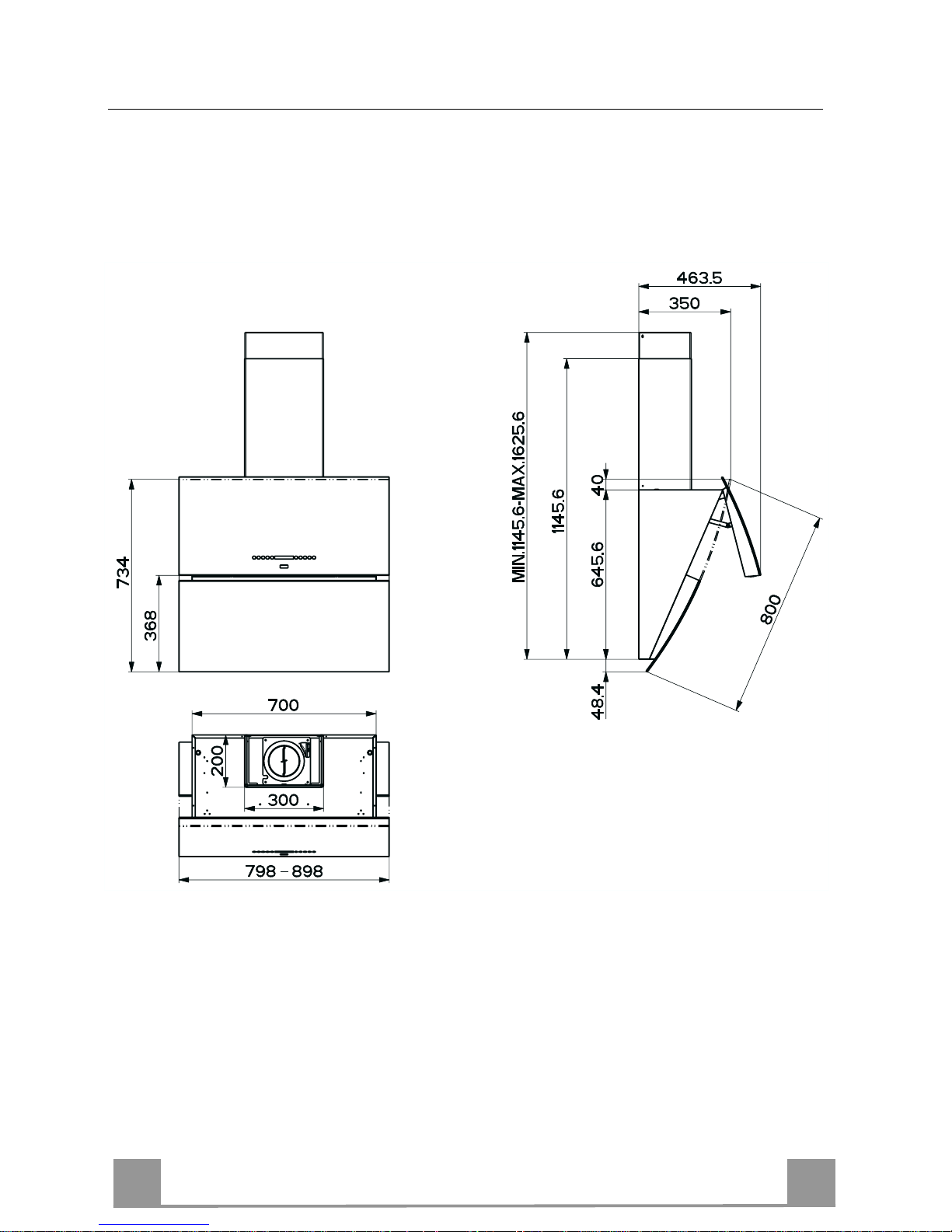
Dimensions
Page 12

EN
112
INSTALLATION
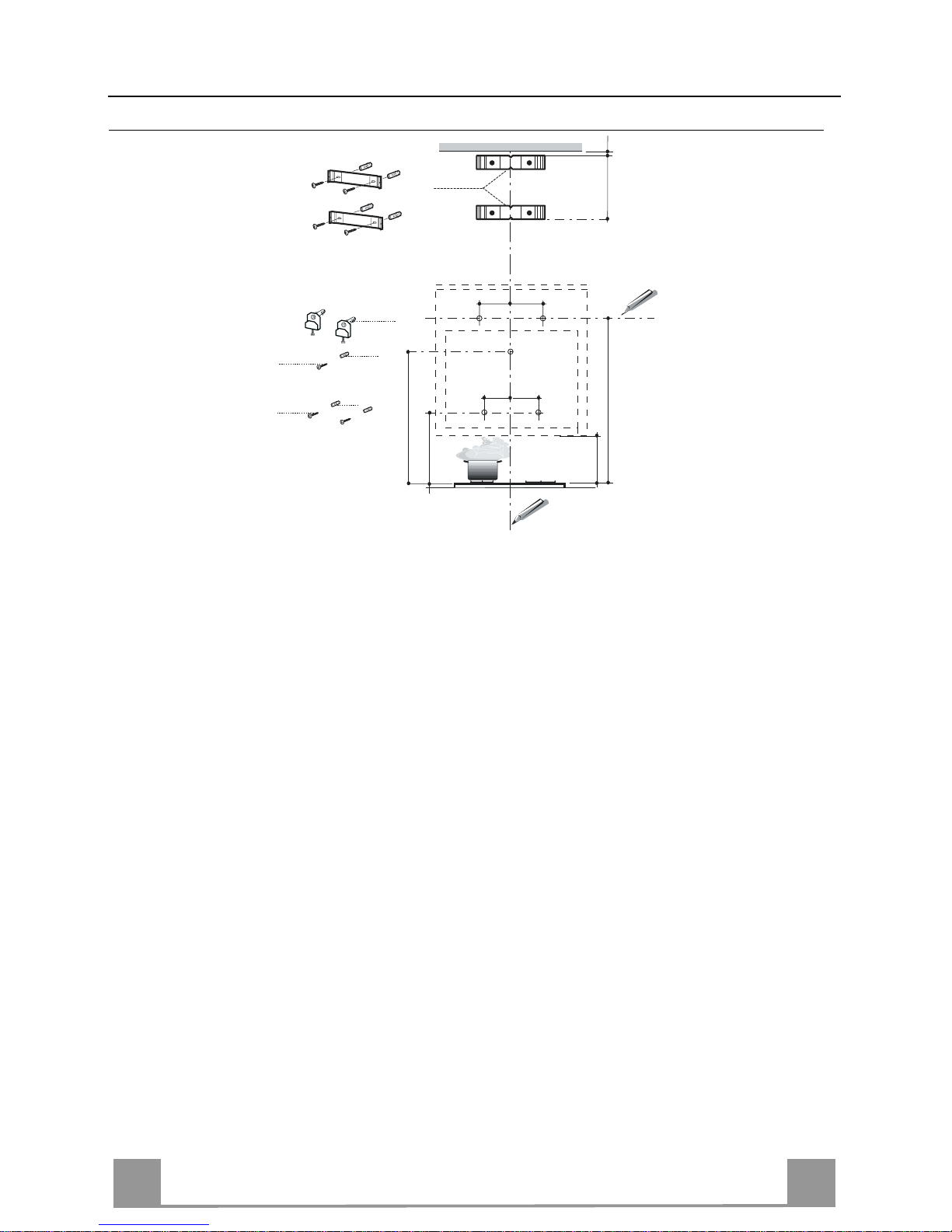
Wall drilling and bracket fixing
As a first step, proceed with the following dr awin gs:
• a vertical line up to the ceiling or up to the upper limit, at the centre of the area in which the
hood is to be fitted;
• a horizontal line at a minimum 960 mm above the cooker top.
• Mark a point (1) on the horizontal line, 292 mm to the right of the vertical reference line.
• Repeat this operation on the other side, checki ng that the two marks are levelled.
• Mark a reference point (2) as indicated at 200 mm from the vertical referenc e line and 458
mm above the cooker t op.
• Repeat this operation on the other side, checki ng that the two marks are levelled.
• Mark a reference point (3) at 743 mm above the cooker top on the vert i cal reference line.
• Drill at the marked points (1), using a ø 12 mm drill bit.
• Drill at the marked points (2) and (3), using a ø 8 mm drill bit.
• Insert the bracket plugs 11a into the holes (1) and tighten the screws.
• Insert plug 11 into holes (2) and (3).
• Place bracket 7.2.1 on the wall, about 1-2 mm from the ceiling or from the upper limit,
aligning the centre (notch) with the vertical reference line.
• Mark the wall at the centres of the bracket holes.
• P lace the br acket 7.2.1 on the wall at X mm below the first br acket (X = h eight of the upp er
chimney section) , aligning the centre (notch) with the vertical line.
• Mark the wall at the centres of the bracket holes.
• Drill ø 8 mm holes at all the marked centre points.
• Insert the wall plugs 11 in the holes.
• Fix the brackets using the 12a screws (4,2 x 44,4) supplied with the hood.
11a
1
1
22
200
11
12a
11
12a
3
292 292
960
458
X
1÷2
7.2.1
368
200
743
Page 13

EN
113
Hood body mounting
• Firstly, it is necessary to adjust the two Vr-scre ws of
the 11a-brackets, at minimun (B).
• Hang the hood body on the two brackets 11a.
• Connect the hood to the mains supply by means of a
bipolar switch with at le as t 3 mm contact gap.
• Press the “A”-key for one second (see Part USE) to
open the upper pa ne l.
• Remove the metal filters.
• In order to align the hood it is necessary to adjust the
Vr-screws from inside the hood.
• Fasten the safety screw 11.
• Fit again the metal filters into th eir seats and clo se the
upper panel by pressing “L”-key for one second (see
Part USE).
• Disconnect the hood f r om the mains s upply.
Attention: the upper panel stops if a ny barri er occ urs in i ts
way during the panel opening or closing. To open the panel
it is enough to remove the barrier and pres s the key once
again.
(B)
L
A
11a
Vr
11
Connections
DUCTED VERSION AIR EXHAUST SYSTEM
When installing t he ducted versi on, conn ect the hood to
the chimney using either a flexible or rigid pipe ø 150
or 120 mm, the choice of which is left to the installer.
• To install a ø 120 mm air exhaust connection, insert
the reducer flange 9 on the hood body outlet.
• Fix the pipe in position using sufficient pipe clamps
(not supplied).
• Remove possible charcoal filters.
ø 150
9
ø 120
Page 14

EN
114
RECYCLING VERSION AIR OUTLET
To install the hood in recycling version, the optional charcoal
filter kit must be purchased.
• Remove the chimney angle bracket.
• Screw the filter cover onto the air outlet, using four screws 12c
(2.9 x 12.5).
• Fix the air outlet grid 8 on the recirculation air outlet using the
2 screws 12d (2,9 x 9,5) provided.
16
12c
12d
8
ELECTRICAL CONNECTION
• Connect the hood to the mains supply.
• Open the upper panel by pressing the A-key (See Part “USE” )
for at least 2 seconds.
• Remove the metal filters (See Part “MAINTENANCE”) and
make sure that the connector piece of the supply cable is correctly inside the hood socket.
Chimney assembly
Upper exhaust Chimney
• Slightly widen the two sides of the upper chimney and hook
them behind the brackets 7.2.1, making sure that they are well
seated.
• Secure the sides to t he brackets using th e 4 screws 12c (2,9 x
9,5) supplied.
Lower exhaust Chimney
• Slightly widen the two sides of the chimney and hook them
between the upper chimney and the wall, making sure that they
are well seated.
• Fix the lower part laterally to the hood body using the 2 screws
12c (2,9 x 9,5) supplied.
12c
2.1
2.2
2
7.2.1
12c
Page 15

EN
115
USE
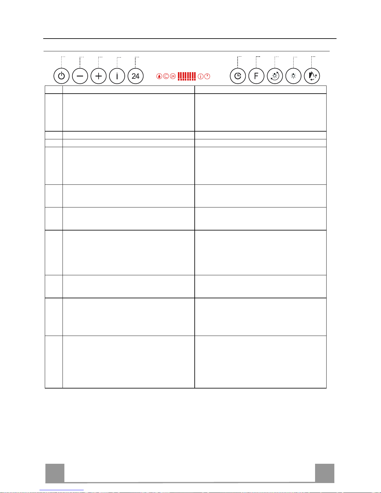
Control panel
Key Function Display
A Upper panel closed: when pressed for about one sec-
ond it opens the upper panel. It switches the motor on
at the latest sele cte d spe ed.
Upper panel open: when shortly pressed it switches
the motor o n/o ff .
Indicates the selected speed.
B Decreases the suction speed. Number of lit LEDS decreases.
C Increases the suction speed. Number of lit LEDS increases.
D Functioning only when the upper panel is open. This
speed h as been tim ed at 10 min utes. After t hat time
the system activates automatically the latest selected
speed. The function is suitable for cooking conditions
when vapour s and s m e lls are of the utm o s t e m is sio n.
I flashes and all the LEDS on th e display
are lit.
By pressing the key the function is deactivated.
E Functioning only when the upper panel is open. By
pressing this key it is possible to set up the motor to a
suction spee d at 1 00 m
3
/h .
24–symbol appears and the LEDS on the
display go o ff cy clically, one by one.
By pressing the key the function is deactivated.
F Functioning only when the motor is on. By pressing
this key it is possible to set the delayed shutdown of
the motor and t he lighting to 30 m in ute s .
A flashing clock symbo l appears.
By pressing the key the function is deactivated.
G By pressing this key for about 2 seconds it is possible
to reset the fil te r sa tur atio n al ar m .
A drop symbol indicates that the metal
grease filters saturation alarm has been
activated, and the filters need to be
washed. The alarm is triggered after 100
working ho ur s.
C indicates that the charcoal filter saturation alarm has been activated, and the filter
has to be replaced. The alarm s triggered
after 200 w o r king ho ur s .
H By pressing this key the intensity of the lighting sys-
tem can be modif ied up to five levels.
I Upper panel closed: when pressed for about 1 second
it opens the upper panel and sets the lights at the
maximum inte nsity.
Upper panel open: when shortly pressed it switches
the lights o n/o ff .
L Upper panel closed: when pressed for about one sec-
ond it opens the upper panel and switches the motor
on at the third speed and the lights at the maximum
intensity.
Upper panel open: when pressed for about 1 second it
switches off motor and lights resetting every activated
function, and cl oses the uppe r panel.
Keyboard lock: it is possible to jam the ke yboard when, for examp le, cleaning the gl ass. The
motor and lights are switched off, and upper panel can be open or closed.
By pressing the F-key (Delay) for about 5 seconds the keyboard block can be activated or deactivated. This function is confirmed by a Beep and by moving motor LEDS on display.
B
A
D
C
E
G
F
I
H
L
Page 16

EN
116
REMOTE CONTROL (OPTIONAL)
The appliance can be controlled using a remote control
powered by a 1.5 V carbon-zinc alkaline batteries of the
standard LR03-AAA type.
• Do not place the remote con trol near to heat sources.
• Used batteries must be disposed of in the proper
manner.
Remote control (control panel)
T1 Lighting Upper panel closed: opens the upper panel and sets the lights at the maximum inten-
sity.
Upper panel open: switches th e lights on/off.
T2 Courtesy light Sets the lights at an intermediate intensity or switches the lights off (only when the
upper panel is open).
T3 Motor Upper panel closed: opens the upper panel, switches on the motor at the latest se-
lected speed.
Upper panel open: switches the motor on/off.
When pressed for about 2 Seconds:
upper panel closed: opens the upper panel and switches on the motor at the third
speed and the lights at the maximum intensity.
Upper panel open: switches off lights and motor and closes the upper panel.
T4 Decreases the speed at every short pressure.
When pressed for about 2 Seconds:
decreases the intensity of lights.
T5 Increases the s peed at ever y short pressure.
When pressed for about 2 Seconds:
Increases the intensity of lights.
T6 Activates/deacti vates the intensive speed.
T7 Delay / 24h Activates / deactivates the Delay-function.
When pressed for 2 seconds :
Activates/deactivates the 24H-funct i on.
T1
T6
T2
T3
T4
T5
T7
Page 17

EN
117
MAINTENANCE
Metal grease filters
Filters can be washed in the dish machine. They need to be
washed when Drop-sign appears on the display or in any case
every 2 months, or even more frequently in case of particularly
intensive use of the hood.
Alarm reset
• Press the G–key for at least 2 seconds.
Cleaning the filters
• Open the upper panel by pressing the A-key for 1 second (see
Part USE).
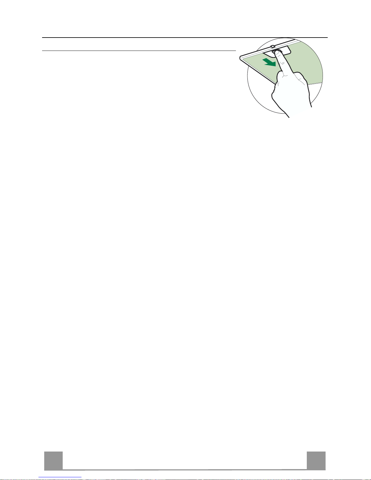
• Remove the filters one by one pushing them towards the back
side of the hood unit and simultaneously pulling downwards.
• Any kind of bending of the filters has to be avoided when
washing them. Before fitting them again into the hood make
sure that they are completely dry. (The colour of the filter surface may change throughout the time but this has no influence
to the filter efficiency).
• When fitting the filters into the hood pay attention that they are
mounted in correct position the handle facing outwards.
Page 18

EN
118
Charcoal filter (recycling version)
This filter cannot be washed or regenerated. It must be replaced when the C appears on the
display or at least once every 4 months. The filter saturation alarm has to be activated already
before.
Activation of the alar m signal
• In the recycling version hoods the filter saturation alarm must be activated during the installation or later.
• Switch off the hood and the lights.
• Press the E-key for about 5 seconds until the last two segments of the motor LEDS are lit on
the display.
• By releasing the E-key the clock ico n starts to flash.
• Within 3 seconds press the D-key to activate/deactivate charco al filter saturation alarm.
• C-symbol lit - charcoal filter saturation alarm ACTIVATED.
• C-symbol unlit - charcoal filter saturation alarm DEACTIVATED.
REPLACING THE CHARCOAL FILTER
Alarm reset
• Press the G-key for at least 2 seconds.
Replacing the filter
• Open the upper panel by pressing the A-key for about a second
(see Part USE).
• Remove the metal filters.
• Remove the saturated charcoal filter as indicated (A).
• Fit the new filters as indicated (B).
• Put the metal grease filters in their seats.
A
B
Lighting
LIGHT REPLACEMENT
20 W halogen light.
• Extract the lamp from the lamp holder by pulling gently.
• Replace with another of the same type, making sure that the
two pins are properly inserted in the lamp holder socket holes.
Page 19

EN
119
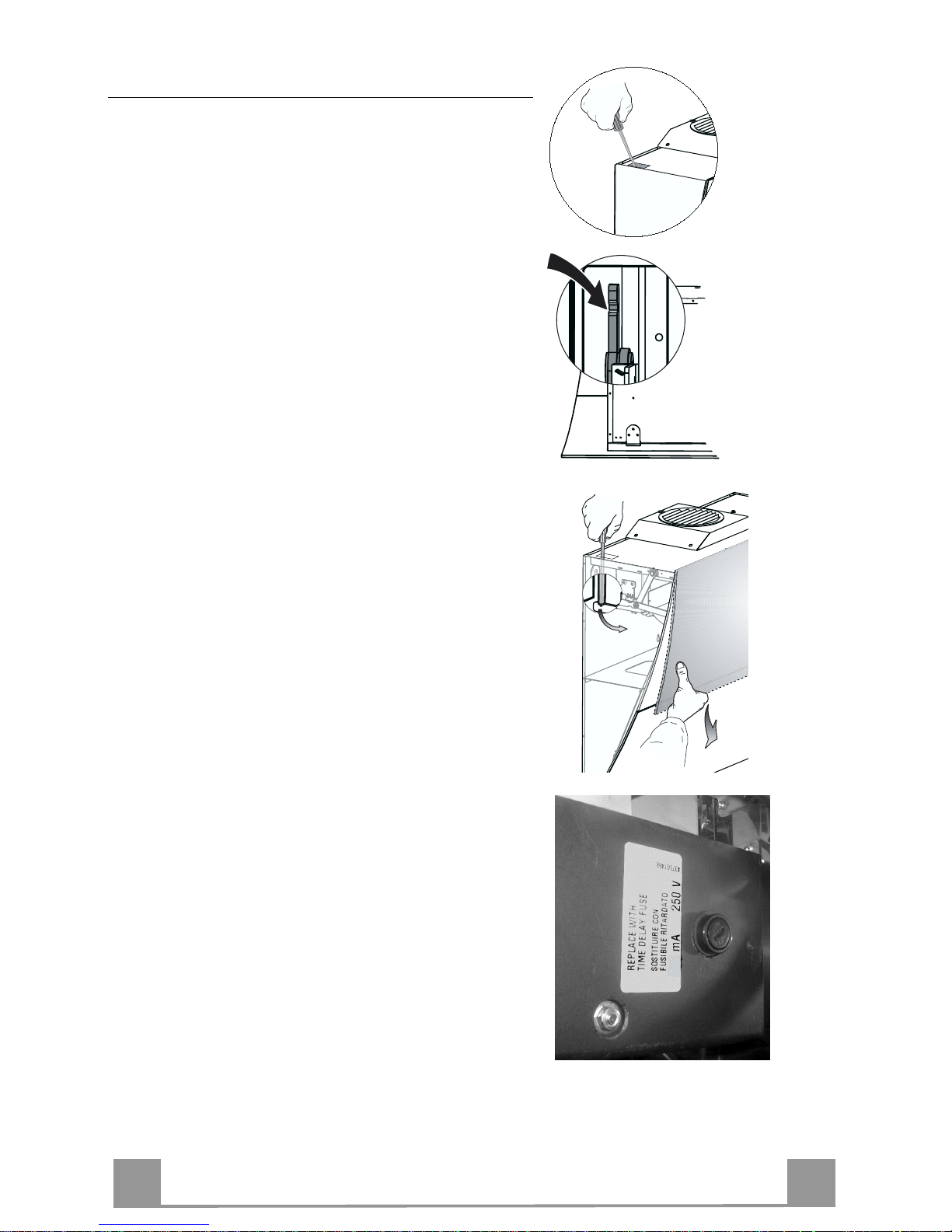
Replacing the fuser
The hood panel opening and closing mechanism is controlled by a starter motor which is activated by a fuser.
This fuser works only on th e starter motor. In case the
fuser gets damaged when the panel is closed it is be
necessary to manually unblock the panel. In this case
proceed as follo ws:
• Remove the cover placed up on the left side.
• Press the releasing lever with the screwdriver as
much as necessary to enable the manual opening of
the panel.
• After having completely opened the panel remove the
metal grease filters, as explained in the part concerning the filter cleaning.
• The fuser is placed up on the right side. Turn the
fuser holder as indi cated. Replace the fuser with o ne
having the same features.
• Put the fuser h older and grease filters i nto their place
again. Make sure that th e hood functi ons co rrectly. In
case the panel doesn ’t work correctly it is necessary
to contact an authorized technician.
If the fuser gets damaged being the panel open, it is sufficient to simply remove the grease filters and replace
the fuser.
Page 20

FR
220
CONSEILS ET SUGGESTIONS
La présente notice d'emploi vaut pour plusieurs versions de l'appareil.
Elle peut contenir des descriptions d'accessoires ne figurant pas dans
votre appareil.
INSTALLATION
• Le fabricant décline toute responsabili té en cas de dommage dû à une
installation non correcte ou non conforme aux règles de l’art.
• V érifier que la t ension du sec teur correspond à la valeur qui figure s ur la
plaquette apposée à l’intérieur de la hotte.
• Pour les Appareils appartenant à la Ière Classe, veiller à ce que lamise à
la terre de l’installation électrique domestique ait été effectuée conformément aux normes en vigueur.
• Connecter la hotte à la sortie d’air aspiré à l’aide d’une tuyauterie d’un
diamètre égal ou supéri eur à 120 mm. Le parcours de la tuy auterie doit
être le plus court possible.
• Eviter de connecter la h otte à des conduites d’évacuation de fumées is sues d’une combustion tel que (Chaudière, cheminée, etc…).
• Si vous utilisez des appareils qui ne fon ctionne nt pas à l’élect ricité da ns la
pièce ou est instal lée l a h otte (p ar exe m pl e: des app arei ls fonctionnant au
gaz), vous devez prévoir une aération suffisante du milieu. Si la cuisine en
est dépourvue, pratiq uez une ouverture qui comm unique avec l’extérieur
pour garantir l’infiltration de l’air pur.
UTILISATION
• La hotte a été conçue exclusivement pour l’usage domestique, dans le but
d’éliminer les odeurs de la cuisine.
• Ne jamais utiliser abusivement la hotte.
• Ne pas laisser les flamm es libres à forte intensité quand la hotte est e n
service.
• Toujours régler les fl ammes de manière à éviter tout e sortie latérale de
ces dernières par rapport au fond des marmites.
• Contrôler les friteuses lors de l’utilisation car l’huile surchauffée pourrait
s’enflammer.
• Ne pas préparer d’aliments flambés sous la hotte de cuisine : risque
d’incendie
• Cet appareil ne doit pas être utilisé par des personnes (y compris les enfants) ayant des capacités psychiq ues, sensorielles ou m entales r éduites,
ni par des personnes n’ayant pas l’ expérience et la connaissance de ce
type d’appareils, à moins d'être sous le con trôle et la formation de personnes responsables de leur sécurité.
• Les enfants doivent être surveillés pour s'assurer qu'ils ne jouent pas
avec l'appareil.
ENTRETIEN
• Avant de procéder à toute opérati on d’entre tien, retirer l a hotte en retirant
la fiche ou en actionnant l’interrupteur général.
• Effectuer un e ntre tien scrupuleux et en tem ps dû des F il tr es, à la cadence
conseillée.
• Pour le nettoyage des surfaces de la hotte, il suffit d’utiliser un chiffon
humide et détersif liquide neutre.
Page 21

FR
221
CARACTERISTIQUES
Composants
Réf. Q.té Composants du produit
1 1 Corps de Hotte comprenant : Commandes, Éclairage,
Groupe Vent ilation, Fil tres
2.1 1 Conduit supérieur
2.2 1 Conduit inf érieur
8 1 Grille orientable Sortie de l’Air
9 1 Buse de réduction 150- -1 20
16 1 Couverture filtrante
Réf. Q.té Composants de l’installation
7.2.1 2 Équerre d e fixation du conduit supérieur
11 7 Chevilles
11a 2 Chevilles SB 12/10
12a 7 Vis 4,2 x 44,4
12c 10 Vis 2,9 x 6,5
12e 2 Vis 2,9 x 9,5
Q.té Documentation
1 Notice d’emploi
1
16
12c
12d
8
9
11a
2.1
2.2
12c
12a
7.2.1 11
11
12a
11
12a
Page 22

FR
222
Encombrement
Page 23

FR
223
INSTALLATION
Perçage du mur et fixation des équerres
Marquer sur le mur :
• une ligne verticale allant jusqu’au plafond ou jusqu’à la limite supérieure, au centre de la
zone prévue pour le montage de la hotte ;
• une ligne horizontale à 960 mm minimum au-dessus du plan de cuisson.
• Marquer un point (1) sur la ligne horizontale à 292 mm à droite de la ligne verticale de référence.
• Répéter cette opération du côté opposé et vérifier l’alignement.
• Marquer comme indiqué, un point de référence (2) à 200 mm de la ligne verticale de référence et à 458 mm au-dessus du plan de cuisson.
• Répéter cette opération du côté opposé et vérifier l’alignement.
• Marquer, comme indiqué, le point de référence (3) à 743 mm au-dessus du plan de cuisson
sur la ligne verticale de référence.
• Percer les points (1) avec une mèche de ø 12 mm.
• Percer les points (2) et (3) avec une mèche de ø 8 mm.
• Mettre les chevilles avec l’équerre 11a dans le s trous (1) et visser.
• Mettre la cheville 11 dans les trous (2) et (3).
• Comme indiqué, poser l’équerre 7.2.1 à 1-2 mm du plafond ou de la limite supérieure, en
alignant le centre (entailles) avec la ligne verticale de référence.
• Marquer les centres des trous de l’équerre.
• Comme indiqué, poser l’équerre 7.2.1 à X mm en dessous de la première équerre (X = hauteur du conduit supérieur fourni avec la hotte), en alignant le centre de l’équerre (entailles)
avec la ligne verticale de référence.
• Marquer les centres des trous de l’équerre.
• Percer les trous avec une mèche d e ø 8 mm.
• Mettre les chevilles 11 dans les trous.
• Fixer l’équerre à l’aide des vis 12a (4,2 x 44,4) fournies avec l’appareil.
11a
1
1
22
200
11
12a
11
12a
3
292 292
960
458
X
1÷2
7.2.1
368
200
743
Page 24

FR
224
Montage du corps de la hotte
• Placer les deux vis Vr, sur les équerres 11a sans les
visser (B).
• Accrocher le corps de la hotte aux 2 éque rr es 11a .
• Brancher la hotte au réseau électrique en interposant
un interrupteur bipolaire ayant une ouverture des
contacts d’au m oins 3 mm.
• Appuyer sur la Touche “A” pendant 1 seconde (Voir
paragraphe EMPLOI) pour ouvrir le panneau supérieur.
• Ret irer le s filtres à graisse au moyen des po ignées pr évues à cet effet.
• Mettre à niveau le corps de la hotte de l’intérieur en
agissant sur les vis Vr.
• Visser la vis de sécurité 11.
• Remonter les filtres à graisse, fermer le panneau supérieur en appuyant pendant 1 seconde sur la touche “L”
(Voir le paragraphe EMPLOI).
• Débrancher la hotte du réseau électrique.
Attention : Si, pendant l’ouverture ou la fermeture, la porte
rencontre un obstacle et se bloque, il suffit de retirer
l’obstacle et d’appuyer à nouveau s ur la touc he pour que la
porte s’ouvre.
(B)
L
A
11a
Vr
11
Branchements
SORTIE AIR VERSION ASPIRANTE
En cas d’installation en version aspirante, brancher la
hotte à la tuyauterie de sortie via un tube ri-gide ou
flexible de ø 150 ou 120 mm, au choix de l’installateur.
• En cas de branchement avec un tube de ø120 mm,
insérer le flasque de réduction 9 sur la sortie du corps
de la hotte.
• Fixer le tube par des colliers appropriés. Le matériau
nécessaire n’est pas fourni.
• Retirer les éventuels filtres anti-odeur au charbon
actif.
ø 150
9
ø 120
Page 25

FR
225
SORTIE AIR VERSION FILTRA NTE
Pour l’installation dans la Version Filtrante, il faut acheter le kit
fourni sur demande Cartouche au charbon actif.
• Enlever la cornière de la cheminée
• Visser le couvercle filtrant sur la sortie de l’air, en utilisant les
quatre vis 12c (2,9 x 6,5).
• Fixer la Grille orientée 8 sur la sortie de l’air rec yclé à l’aide
de 2 Vis 12d (2,9 x 9,5) fournies avec l’appareil.
16
12c
12d
8
BRANCHEMENT ÉLECTRIQUE
• Débrancher la hotte du réseau électrique.
• Appuyer sur la Touche “A” pendant plus de 2 secondes (Voir
le paragraphe EMPLOI) pour ouvrir le panneau supérieur.
• Retirer les filtres à graisse (Voir le paragraphe EMPLOI) et
s’assurer que le conn ecteur du câble électri que est introdu it de
façon correcte dans la prise d’aspiration.
Montage Cheminée
Cheminée supérieure
• Elargir légèrement les deux bords latériau x, et les accrocher
derrières les brides 7.2.1; refermer jusqu’à la butée.
• Fixer latéralement aux brides à l’aide des 4 vis 12c fournies.
Cheminée inférieure
• Elargir légèrement les deux bords latériaux de la Cheminée et
les accrocher entre la Che minée supérieure et la p aroi; refermer
jusqu’à la butée.
• Fixer latéralement la partie inférieure au corps hotte, à l’aide
des deux 2 vis 12c fournies.
12c
2.1
2.2
2
7.2.1
12c
Page 26

FR
226
UTILISATION
Tableau des commandes
Touche
Fonction Afficheur
A
Porte fermée : Une pression d’un e seconde env.
sur cette touche ouvre la porte et met le moteur en
marche à la dernière vitesse réglée.
Porte ouver te : Une brève p ression su r cette touche éteint ou allume le mot eur.
La vitesse choisie s’affiche.
B
La vitesse de service diminue. Les segments allumés diminuent.
C
La vitesse de service augmente. Les segments allumés augmentent.
D
Cette touche s’active uniquement quand la porte
est ouverte ; cette vitesse est programmée pour 10
minutes, après quoi le système retourne à la vitesse régl ée au préalab le. Apte à fair e face à une
quantité maximale de fumées de cuisson.
I clignote et les segments affichés sont tous
allumés.
Appuyer sur la touche pour désactiver.
E
Cette fonction s’active uniquement avec la porte
ouverte ; elle met en marche le moteur à un e vitesse permettant une aspiration de 100 m3/h.
24 s’affiche et les segments affichés qui
étaient tous allumés s’éteignent un à un de
manière cyclique.
Appuyer sur la touche pour désactiver.
F
Cette fonction s’active uniquement quand le moteur est en marche ; elle éteint le moteur automatiquement et l’éclairage après 30' de retard.
Le symbole d’une horloge qui clignote
s’affiche
Appuyer sur la touche pour désactiver.
G
Rétablit l’alarme de saturation des filtres en appuyant sur la touche pendant environ 2 secondes.
Le symb ole Goutte s’affiche après 100 heures de service pour signaler la saturation des
filtres métalliques.
C s’affich e après 200 heu res d e servi ce po ur
signaler la saturation des filtres au charbon
actif.
H
Chaque pression sur cette touche modifie de façon cyclique l’intensité de l’éclairage jusqu’à un
maximum de 5 niveaux.
I
Porte fermée : Appuyer sur cette touche pendant
env. 1 seconde pour ouvrir la porte et allumer les
lumières à l’intensité maximale.
Porte ouverte : Une brève pression allume ou
éteint les lumières .
L
Porte fermée : Appuyer sur cette touche pendant
env. 1 seconde pour ouvrir la porte, mettre en
marche le moteur à la troisième vitesse et allumer
les lumières à l’intensité maximale.
Porte ouverte : Appuyer sur cette touche pendant
env. 1 seconde pour tout éteindre, moteur et lumières, rem ettre t oute fon ction active à l’ état i nitial et fermer la porte.
Commande de blocage du Clavier : Il est possible de bloquer le clavier, par exemple pour nettoyer la vitre, quand l e moteur et les lumières so nt étein ts, avec la p orte au ssi bien ouverte q ue
fermée.
Appuyer sur la touche F (Retard) pendant env. 5 secondes pour activer ou désactiver le blocage du clavier ; cette fonction est toujours confirmée par un bip sonore et une animation qui
s’affiche sur la barre du moteur.
B
A
D
C
E
G
F
I
H
L
Page 27

FR
227
TELECOMMANDE
Il est possible de commander cet appareil au moyen
d’une télécomman de, ali mentée a vec des pil es alcali nes
zinc-charbon 1,5 V du type standard LR03-AAA.
• Ne pas ranger la télécommande à proximité de sources de chaleur.
• Ne pas jeter les piles; il faut les déposer dans les récipients de récol te spécialement prévus à cet effet.
Tableau des commandes à distance
T1 Écl airage Porte fermée : Ouvre l a porte et allume les lumières à l’intensité maximale.
Porte ouverte : Allume ou éteint les lumières.
T2 Éclairage Allume les lumières à l’intensité moyenne ou les ét eint (Uniquement avec
de courtoisie la porte ouverte).
T3
Moteu r Porte fermée : Ouvre la port e, allume le moteur à la dernière vi tesse réglée.
Porte ouverte : Allume ou éteint le moteur.
Touche appuyée pendant 2 secondes :
Porte fermé e : Ouvr e la port e et allu me le mot eur à la trois ième vit esse avec les lu-
mières à l’intensité maximale.
Porte ouverte : Éteint les lumières , le moteur et f erme la porte.
T4 La vitesse de service diminue à chaque pression.
Touche appuyée pendant 2 secondes :
L’intensité des lumières diminue.
T5 La vitesse de service augmente à chaque pression rapide.
Touche appuyée pendant 2 secondes :
L’intensité des lumières augmente.
T6 Intensive Active/Désactive la vitesse intensive.
T7 Retard / 24h Active/Désactive la fonction Retard..
Touche appuyée pendant 2 secondes :
Active/Désactive la fonction 24H.
T1
T6
T2
T3
T4
T5
T7
Page 28

FR
228
ENTRETIEN
Filtres à graisse métalliques
Ils sont lavables même en lave-vaisselle et doivent être lavés
chaque fois qu e le symbo le Goutte s’affiche ou au moins tou s les
2 mois environ ou plus souvent, en cas d’utilisation particulièrement intensive.
Rétablissement du signal d’alarme
• Appuyer sur la touche G pendant au moins 2 secondes.
Nettoyage des filtres
• Si la porte est fermée, appuyer sur la touche A pendant environ
1 seconde pour l’ouvrir (Voir EMPLOI).
• Retirer les filtres, un à un, en les poussant vers l’arrière du
groupe tout en les tirant vers le bas.
• Laver les filtres en évitant de les plier, et les faire sécher avant
de les remonter. (Tout ch ange me nt de co uleu r sur l a surface du
filtre, susceptible de se produire avec le temps, ne nuit en rien
l’efficacité de ce dernier.)
• Remonter les filtres en faisant attention de tenir la poignée vers
la partie externe visible.
Page 29

FR
229
Filtres anti-odeur au charbon actif (version filtrante)
Il ne peut être ni lavé ni récupéré, il faut le changer quand le symbole C s’affiche ou au moins
tous les 4 mois. Il faut tout d’abord activer le signal d’alarme.
Activation du signal d’alarme
• Pour les hottes en version filtrante, l’alarme indiquant la saturation des filtres doit être activée au moment de l’installation ou ultérieurement.
• Éteindre les lumières et le moteur d’aspiration.
• Appuyer sur la touche E pendant 5 sec. environ, jusqu’à ce que les deux derniers segments
et toute la ligne en pointillés de la barre Moteur s’allument sur l’afficheur.
• Relâcher la touche E, l’icône “Horloge” commencera à cli gnoter.
• Appuyer sur la touche D dans les 3 seconde s qui sui vent pour activer/désactiver les filtres
au C.A.
• Le symbole C s’allume : alarme de saturation du filtre au C.A. ACTIVÉE
• Le symbole C s'éteint : alarme de saturation du filtre au C.A. DÉSACTIVÉE
REMPLACEMENT DU FILTRE ANTI-ODEUR AU CHARBON ACTIF
Rétablissement du signal d’alarme
• Appuyer sur la touche G pendant au moins 2 secondes.
Remplacement du Filtre
• Si la porte est fermée, appuyer sur la touche A pendant environ
1 seconde pour l’ouvrir (Voir EMPLOI).
• Retirer les Filtres à graisse.
• Retirer les filtres anti-odeur au charbon actif saturés, selon les
indications (A).
• Placer les nouveaux filtres, selon les indications (B).
• Remonter les Filtres à graisse.
A
B
Eclairage
REMPLACEMENT LAMPES
Lampe halogène de 20 W.
• Sortir la Lampe de la Douille en exerçant une légère traction.
• Re mplacer par u ne nouvelle lampe possédant les mêmes caractéristiques, en veillant à ce que les deux fiches soient correctement insérées dans le logement de la Douille.
Page 30

FR
330
Remplacement du fusible
Le fusible agit uniquement sur le moteur qui gère le
mouvement d’ouverture et de fermeture de la porte.
Ainsi, si le fusible doit être changé quand la porte est
fermée, il faudra la débloquer manuellement, selon la
procédure décrite ci -après :
• Retirer le couvercle situé à l’angle supérieur gauch e.
• Prendre un tourne-vis et exercer une pression sur le
levier de déblocage, jusqu’à ce que la porte s’ouvre
suffisamment pour passer la main et l’ouvrir complètement.
• Une fois la porte ouverte complètement, retirer les
filtres à graisse métalliques selon la procédure décrite
au paragraphe “Nettoyage des filtres à graisse”.
• Le fusible est situé en haut à droite ; tourner le portefusible selon les ind ications fournies et remplacer le
fusible avec un aut re fusible ayant les mêmes caractéristiques.
• Remettre le porte-fusible en place ainsi que les filtres
à graisse, vérifier que la hotte fonctionne bien. Dans
le cas où la porte continue à ne pas fonctionner,
contacter un technicien autorisé.
Si le fusible est à changer quand la porte est déjà ouverte, il suffit de retirer les filtres à graisse et de le remplacer.
Page 31

DE
331
EMPFEHLUNGEN UND HINWEISE
Diese Gebrauchsanleitung gilt für mehrere Geräte-Ausführungen. Es ist
möglich, dass einzelne Ausstattu ngsmerkmal e beschriebe n sind, die nicht
auf Ihr Gerät zutreffen.
MONTAGE
• Der Hersteller haftet nich t für Schäden, die auf eine fehlerhafte und un sachgemäße Montage zurückzuführen sind.
• Prüfen, ob die Netzspannu ng mit dem Wert auf dem im Haubeninnere n
angebrachten Schild übereinstimmt.
• Bei Geräten der Klasse I ist sicherz ustellen, dass die el ektrische Anlage
des Wohnhauses über eine vorschriftsmäßige Erdung verfügt.
• Das Anschlussrohr der Haube zur Luftaustrittsöffnung muss einen
Durchmesser von 120 mm oder darü be r aufweisen . Der Rohrverlauf muss
so kurz wie möglich sein.
• Die Haube darf an k eine Entlüftungsschächte angeschloss en werden, in
die Verbrennungsgase (Heizkessel, Kamine usw.) geleitet werden.
• Werden im Raum außer der Dunstabzugsha ube andere, nicht elektrisc h
betriebene (z.B. ga sbetriebene) Ge räte verwendet, muss f ür eine ausreichende Belüftung gesorgt werden. Sollte die Küche diesbezüglich nicht
entsprechen, ist an einer Aussenwand eine Öffnung anzubringen, die
Frischluftzufuhr gewährleiste t.
BEDIENUNG
• Die Dunstabzugsh aube ist ausschließlich zum E insatz im privaten Haushalt und zur Beseitigung von Küchengerüchen vorgesehen.
• Unsachgemäßer Einsatz der Haube ist zu unterlassen.
• Große Flammen bei eingeschalteter Haube niemals unbedeckt lassen.
• Di e Intensivität der Flamme ist so zu regulieren, dass sie den Topf boden
nicht überragt.
• Frittiergeräte m üssen während des Gebrauc hs stets beaufsichtigt werde n:
überhitztes Öl kann sich entzünden.
• Keine flambierten Spei sen unter der Abzugshaube zubereiten: Brandg efahr.
• Dieses Gerät darf nicht von Personen, auch Kindern, mit verminderten
psychischen, sensorischen und geistigern Fähigkeiten, oder von Personen ohne Erfahru ng und Kenn tnisse benutzt werden, sofern sie nicht von
für ihre Sicherheit verantwortlichen Personen beaufsichtigt und beim
Gebrauch des Geräts angeleitet werden.
• Kinder dürfen sich nicht unbeaufsic htigt in der N ähe des Ge räts auf halte n
und auf keinen Fall mit dem Gerät spielen.
WARTUNG
• Bevor Wartungsa rbeiten durchgeführt werden , muss die Stromzufuhr zur
Haube unterbrochen werden, indem der Stecker gezogen oder der
Hauptschalter abgeschaltet wird.
• Bei der F ilterwartung müssen die vom Hersteller em pfohlenen Zeiträume
zum Austauschen der Filter genauestens eingehalten werden.
• Zur Reinigung der Haub enflächen Wir empfehlen ein feuchtes Tuch un d
ein mildes Flüssigreinigungsmittel.
Page 32

DE
332
CHARAKTERISTIKEN
Komponenten
Bez. Menge Produktkomponenten
1 1 Haubenkörper komplett mit: Steuerungen, Beleuch-
tung, Ventilatorgru ppe, Filter
2.1 1 Oberer Kaminteil
2.2 1 Unterer Kaminteil
8 1 Luftstromrichtungsgitter Luftauslass
9 1 Reduktionsflansch 150-120
16 1 Filterdeckel
Bez. Menge Installationskomponenten
7.2.1 2 Befestigungsbügel oberer Kamin
11 7 Dübel
11a 2 Dübel SB 12/10
12a 7 Schrauben 4,2 x 44,4
12c 10 Schrauben 2,9 x 6,5
12e 2 Schrauben 2,9 x 9,5
Menge Dokumentation
1 Betriebsanleitung
1
16
12c
12d
8
9
11a
2.1
2.2
12c
12a
7.2.1 11
11
12a
11
12a
Page 33

DE
333
Platzbedarf
Page 34
DE
334
MONTAGE
Bohren der Wand und Befestigung der Bügel
An der Wand anze ic hne n:
• eine senkrechte Linie bis zur Decke oder zum oberen Rand in der Mitte des Installationsbereichs der Haube,
• eine waagrec hte Li nie m inde s tens 960 mm oberhalb der Koc hm ulde .
• 292 mm rechts von der senkrechten Bezugslinie einen Punkt (1) auf der waagrechten Linie
kennzeichnen.
• Diesen Vorgang an der gegenüberliegenden Seite wiederholen und die Ausrichtung überprüfen.
• Wie angegeben 200 mm rechts von der senkrechten Bezugslinie und 485 mm oberhalb der
Kochmulde einen Punkt (2) k e nnz e ic hne n.
• Diesen Vorgang an der gegenüberliegenden Seite wiederholen und die Ausrichtung überprüfen.
• Wie angegeben 743 mm oberhalb der Kochmulde einen Punkt (3) auf der waagrechten Bezugslinie kennzeichnen.
• Die gekennze ichne te n Punkte (1) mit ei nem Bohrer ø 12 mm bohr en.
• Die gekennze ichne te n Punkte (2) und (3) mit e i nem Bohrer ø 8 mm bohren.
• Die Dübel mit dem Büge l 11a in die B ohrung e n (1) ei nf üge n und festschrauben.
• Den Dübel 11 in die Bohrung e n (2) und (3) einfügen.
• Den Bügel 7.2.1 wie angegeben 1-2 mm unterhalb der Decke oder der oberen Begrenzung an-
legen und seinen Mittelpunkt (Ein s c hnitte ) an de r senk rec hten Bez ugs linie aus ric hten.
• Die Mitte der Löcher des Bügels kennzeichne n.
• Den Bügel 7.2.1 wie angegeben X mm unterhalb des ersten Bügels (X = Höhe des mitgeliefer-
ten oberen Kaminteils) anlegen und seinen Mittelpunkt (Einschnitte) an der senkrechten Bezugslinie ausrichten.
• Die Mitte der Löcher des Bügels kennzeichne n.
• Die gekennze ichnete n Punkte mit einem Bohrer ø 8 mm bohren.
• Die Dübel 11 in die Bohrungen einfügen.
• Die Bügel mit den mitgelieferten Schrauben 12a (4,2 x 44,4) fix i eren.
11a
1
1
22
200
11
12a
11
12a
3
292 292
960
458
X
1÷2
7.2.1
368
200
743
Page 35

DE
335
Montage des Haubenkörpers
• Die beiden Schrauben Vr der Bügel 11a so regulieren,
dass sie nur bis zum Gewindebeginn (B) eingeschraubt
sind.
• Den Haubenk örpe r be i de n 2 Bügeln 11a einhaken.
• Die Haube an die Stromversorgung anschließen. Einen
Zweipolschalter mit Kontaktöffnungsweite von mindestens 3 mm dazwischensetzen.
• Zum Öffnen des oberen Paneels die Taste “A” (siehe
Abschnitt GEBRAUCH) eine Sekunde lang gedrückt
halten.
• Die Fettfilter mit den entsprechenden Griffen demontieren.
• Vom Haubeninneren her den Haubenkörper mit Hilfe
der Schrauben Vr ausrichten.
• Die Sicherheitsschraube 11 festziehen.
• Die Fettfilter wieder montieren, zum Schließen des
oberen Paneels die Taste “L” (siehe Abschnitt
GEBRAUCH) eine Sekunde lang drücken.
• Die Haube von de r Str om ve r sorg ung tr e nne n.
Achtung: Wird die Tür beim Öffnen oder Schließen durch
ein Hindernis blocki ert, das Hinde rnis entfern en und erneu t
die Taste drücken, damit sich die Tür öffnet.
(B)
L
A
11a
Vr
11
Anschlüss in abluftversion
Bei Abluftbetrieb kann die Haube vom Installateur
wahlweise mittels Rohr oder Schlauch (ø 150 oder 120
mm) an die Außenrohrleitung angeschlossen werden.
• Bei Verwendung eines Anschlussrohres ø 120 den
Reduzierflansch 9 am Haubenaustritt anbringen.
• Das Rohr mit geeigneten Rohrschellen fixi eren. Das
hierzu erforderliche Material wird ni cht mitgeliefert.
• Eventuell vorhandene Aktivkohlefilter entnehmen.
ø 150
9
ø 120
Page 36

DE
336
ANSCHLUSS IN UMLUFTVERSION
Für die Installation in Umluftversion muss das optionale Kit „Aktivkohle-Filtereinsatz“ erworben werden.
• Das Winkelstück der Kaminbefestigung entfernen
• Den Filterdeckel am Luftausgang mit den vier Schrauben 12c
(2,9 x 6,5) fixieren.
• Das Luftleitgitter 8 mit Hilfe von 2 der mitgelieferten Schrau-
ben 12d (2,9 x 9,5) beim Austritt der rückzuführenden Luft fixieren.
16
12c
12d
8
ELEKTROANSCHLUSS
• Die Haube wieder an die Stromversorgung anschließen.
• Z um Öffnen d es ob eren Pan eels di e Taste “A” (siehe Abschnitt
“Gebrauch”) länger als 2 Sekunden gedrückt halten.
• Die Fettfilter entfernen (siehe Abschnitt “Wartung”). Kontrollieren, dass der Verbinder des Stromkabels korrekt in der
Steckdose des Sauggerätes sitzt
Kaminmontage
Oberer Kaminteil
• Die beiden seitlichen Schenkel leicht auseinanderbiegen, hinter
den Bügeln 7.2.1 einhängen und bis zum Anschlag wieder
schließen.
• Bei den Bügeln mit Hilfe der 4 mitgelieferten Schrauben 12c
fixieren.
Unterer Kaminteil
• Die beiden seitlichen Schenkel des Kaminteils leicht auseinanderbiegen, zwischen dem oberen Kaminteil und der Wand einhängen und bis zum Anschlag wieder schließen.
• Den unteren Teil seitlich am Haubenkörper mit 2 der mitgelieferten Schrauben 12c fixieren.
12c
2.1
2.2
2
7.2.1
12c
Page 37

DE
337
BEDIENUNG
Bedienfeld
Taste Funktion Display
A Tür geschlossen: Zum Öffnen der Tür und Ein-
schalten des Motors auf der zuletzt eingestellt en
Gebläsestufe ca. 1 Sekunde lang drücken.
Tür geöffnet: Zum Aus- oder Einschalten des
Motors kurz drücken.
Zeigt die eingest ellte Gebläsestufe a n .
B Verringert die laufende Gebläsestufe. Die leuchtenden Segmente nehmen ab.
C Steigert die laufende Gebläsestufe. Die leuchtenden Segmente nehmen zu.
D Diese Gebläsestufe lässt sich nur bei geöffneter
Tür aktivieren und ist auf 10 Minuten begrenzt.
Danach kehrt d as System zur zuvor eingest ellten
Gebläsestufe zurück. Zum Beseitigen sehr starker
Küchendünste geeignet.
I blinkt u nd alle Segm ente au f dem Disp lay
leuchten.
Lässt sich durch Drücken der Taste ausschalten.
E Lässt sich nur bei geöffneter Tür aktivieren.
Schaltet den Motor auf einer Gebläsestufe ein, die
ein Absaugen von 100 m
3
/h erlaubt.
Zeigt 24 an und alle auf dem Display angezeigten Segmente erlöschen allmählich
nacheinander.
Lässt sich durch Drücken der Taste ausschalten.
F Lässt sich bei eingeschaltetem Motor ak tivieren.
Aktiviert das automatische Abschalten des Motors und der Beleuchtung nach 30 Minuten.
Zeigt das Symbol einer blinkenden Uhr an.
Lässt sich durch Drücken der Taste ausschalten.
G Durch ca. 2 Sekunden langes Drücken der Taste
wird die Filtersättigungsanzeige rückgestellt.
Nach 100 Betriebsstunden zeigt das Symbol
Tropfen die Sättigung der Metallfilter an.
Nach 200 Betri ebsstund en zei gt C die Sättigung der Aktivkohlefilter an.
H Steigert die Intensität der Beleuchtung über max.
5 Stufen zyklisch mit jedem Drücken der Taste.
I Tür geschlossen: Zum Öffnen der Tür und Ein-
schalten der Beleuchtung auf der höchsten Stufe
ca. 1 Sekunde lang drücken.
Tür geöffnet: Zum Aus- oder Einschalten der
Beleucht ung k ur z drücken.
L Tür geschlossen: Zum Öffnen der Tür, Einschal-
ten des Motors auf der dritten Gebläsestufe sowie
der Beleuchtung auf der höchsten Stufe ca. 1 Sekunde lang drücken.
Tür geöffnet: Zum Ausschalten aller aktiven
Funktionen, des Motors und der Beleuchtung und
Schließen der Tür ca. 1 Sekunde lang drücken.
Steuerbefehl Tastatursperre: Die Tastatur lässt sich sowohl bei geschlossener als auch bei geöffneter Tür, z.B. zur Reinigung der Scheiben, sperren, wenn Motor und Beleuchtung der
Haube ausgeschaltet si nd.
Zum Aktivieren oder Deakti vieren der Tastatursp erre die Tast e F (Delay) ca. 5 Sekunden lang
drücken. Der Vorgang wird immer durch einen Piepton und die Motorbalkenanzeige auf dem
Display bestätigt.
B
A
D
C
E
G
F
I
H
L
Page 38

DE
338
FERNBEDIENUNG
Dieses Gerät kann mit einer Fernbedienung gesteuert
werden, welche mit alkalischen Zink-Kohle-Batterien
1,5 V des Standardtyps LR03-AAA versorgt wird.
• Die Fernbedienung nicht in die Nähe von Hitzequellen legen.
• Batterien müssen vorschriftsmäßig entsorgt werden.
Bedienfeld Fernbedienung
T1 Beleuch Tür geschlossen: Öffnet die Tür und schaltet die Beleuchtung auf höchster
tung Stufe ein. Tür geöffnet: Schaltet die Beleuchtung ein oder aus.
T2 Nachtbeleu Schaltet die Beleuchtun g auf mittlerer Stufe ein oder schaltet die Beleuch
Chtung tung
aus (nur bei geöffneter Tür).
T3
Motor Tür geschlossen: Öffnet die Tür und schaltet den Motor auf der zuletzt eingestellten
Gebläsestufe ein.
Tür geöffnet : S chaltet den Motor ein oder aus.
Wird die Taste 2 Sekunden lang gedrückt:
Tür geschlossen: Öffnet die Tür und schaltet den Motor auf der dritten Gebläsestufe
sowie di e Beleuchtung auf der höchsten Stufe ein.
Tü r geöffnet: Schaltet die Beleuc htung und den Mot or aus und schließt die Tür.
T4 Verringert die laufende Gebläsestufe bei jedem kurzen Drücken der Taste.
Wird die Taste 2 Sekunden lang ge drückt:
Verringert die Beleuchtungsstufe.
T5 Steigert die laufende Gebläsestufe bei jedem kurzen Drücken der Taste.
Wird die Taste 2 Sekunden lang ge drückt:
Steigert die Beleuchtungsstufe.
T6 Intensivstufe Aktiviert bzw. deaktiviert die Intensivstufe.
T7 Delay / 24h Aktiviert bzw. deaktiviert die Funktion Delay.
Wird die Taste 2 Sekunden lang ge drückt:
Aktiviert bzw. deaktiviert die Funktion 24h.
T1
T6
T2
T3
T4
T5
T7
Page 39

DE
339
WARTUNG
Metallfettfilter
Die Filter können im Geschirrspüler gereinigt werden und sollten
gereinigt werden, wenn das Symbol Tropfen auf dem Display
erscheint bzw. mindestens ca. alle 2 Monate oder bei sehr intensivem Einsatz auch häufiger.
Rückstellen der Sättigungsanze ige
• Die Taste G mindestens 2 Sekunden lang drücken.
Filterreinigung
• Ist die Tür geschlossen, durch ca. 1 Sekunde langes Drücken
der Taste A (siehe GE B RAUCH) ö ffn e n .
• Die Filter einzeln entnehmen, indem sie zur Rückseite der
Gruppe geschoben und gleichzeitig nach unten gezogen werden.
• Die Filter waschen, darauf achten, sie nicht zu verbiegen und
vor der Remontage trocknen lassen. (Eine eventuell im Lauf
der Zeit auftretende Verfärbung der Filteroberfläche hat
keinerlei Einfluss auf die Wirksamkeit des Filters.)
• Bei der Remontage darauf achten, dass sich der Griff an der
sichtbaren Außensei te befindet.
Page 40

DE
440
Aktivkohle-Geruchsfilter (Umluftversion)
Nicht waschbar und nicht regenerierbar. Ersetzen, wenn das Symbol C auf dem Display erscheint bzw. mindestens alle 4 Monate. Das Alarmsignal ist vorher zu aktivieren.
Aktivierung des Alarmsignal s
• Bei Hauben in Umluftversion muss die Aktivierung der Filtersättigungsanzeige bei der Installation oder danac h erfolgen.
• Die Beleuchtung und den Gebläsemotor abschalten.
• Die Taste E ca. 5 Sekunden lang gedrückt halten, bis die beiden letzten Segmente und die
ganze gepunktete Linie der Motoranzeige auf dem Display aufleuchten.
• Die Taste E loslassen. Das Symbol “Uhr” beginnt zu blinken.
• Innerhal b von 3 Se kun den die Taste D zur Aktivierung / Deaktivierung der Aktivkohlefilter drücken.
• Bei Aufleuchten von Symbol C ist die Aktivkohlefilter-Sättigungsanzeige AKTIVIERT.
• Bei Erlöschen von Symbol C ist die Aktivkohlefilter-Sättigungsanzeige DEAKTIVIERT.
ERSETZEN DES AKTIVKOHLE-GERUCHSFILTERS
Rückstellen der Sättigungsanze ige
• Die Taste G mindestens 2 Sekunden lang drücken.
Ersetzen des Filters
• Ist die Tür geschlossen, durch ca. 1 Sekunde langes Drücken
der Taste A (siehe GEBRAUCH) ö ffnen.
• Die Fettfilter ausbauen.
• Die gesättigten Aktivkohle-Fettfilter wie angegeben (A) ent-
nehmen.
• Die neuen Filter wie angegeben (B) montieren.
• Die Fettfilter wieder montieren.
A
B
Beleuchtung
AUSWECHSELN DER LAMPEN
Halogenlampe 20 W.
• Die Lampe vorsichtig aus d er Lampenfassung ziehen.
• Die Lampe durch eine gleichwertige ersetzen und bei der Remontage darauf achten, daß die beiden Steckerstifte vorschriftsmäßig in die Lampenfassung eingeführt werden.
Page 41
DE
441
Auswechseln der Schmelzsicherung
Die Schmelzsicherung dient nur für den Motor, der das
Öffnen und Schließen der Klappe steuert. Falls die Sicherung also ausfällt, während die Klappe geschlossen
ist, muss sie wie folgt von Hand befreit werden:
• Den Deckel an der oberen linken Ecke ausbauen.
• Mit einem Schlitzschraubendreher auf den Entsicherungshebel drücken, bis die Klappe so weit offen ist,
dass sie von Hand vollends geöffnet werden kann.
• Nach dem vollkommenen Öffnen der Klappe die Metallfettfilter ausbauen, wie im Absatz zur Reinigung
der Fettfilter beschrieben.
• Die Schmelzsicherung befindet sich oben rechts; den
Sicherungshalter wie angegeben ausschrauben und
die Sicherung durch eine neue, gleichwerte Sicherung ersetzen.
• Den Sicherungshalter und die Fettfilter wieder einbauen und die korrekte Funktion der Dunsthaube
kontrollieren. Falls die Klappe weiterhin nicht funktionieren sollte, muss ein zugelassener Techniker
hinzugezogen werden.
Fällt die Schmelzsicherung hingegen aus, während die
Klappe geöffnet ist, einfach die Fettfilter ausbauen und
die Sicherung erset zen.
Page 42

ES
442
CONSEJOS Y SUGERENCIAS
Las presentes instrucciones de servicio son válidas para diferentes modelos
de aparato; por ello puede ser posible que se describan detalles y características de equipamiento que no concuerden íntegramente con las de su aparato
concreto.
INSTALACIÓN
• El fabricante declina cualquier responsabilidad debida a los daños provocados
por una ins talación incorrecta o no conforme con las reglas.
• Comprobar que la tensión de red corresponda a la indicada en la placa situada en el interior de la camp a na.
• Para los aparatos de 1ª clase asegurarse de que la instalación eléctrica doméstica posea una toma de tierra ef icaz.
• Conectar la campana a la salida del aire de aspiración mediante un tubo de
120mm de diámetro como mínimo. El recorrido del tubo debe ser lo más corto
posible.
• No conectar la campana a tubos de descarga de humos producidos por combustión (calderas, chimeneas, etc.).
• En e l caso que en la cocina se utilice de mane ra silmultánea la campana y
otros aparatos no eléctricos (por ejemplo aparatos de gas), debe existir un sistema de ventilación suficiente para todo el ambiente. Si la cocina no posee un
orificio que comunique con el externo, hay que realizarlo para garantizar el recambio del aire.
USO
• La campana ha sido concebida exclusivamente para un uso doméstico, para
eliminar los olores de la cocina. No utilizarla de manera inadecuada.
• No dejar llamas libres de fuerte intensidad mientras la campana esté funcionando.
• Regular siempre las llamas de manera que éstas no sobresalgan lateralmente
con respecto al fondo de las ollas.
• Controlar las freídoras durante su uso: el aceite muy caliente se puede inflamar.
• No preparar alimentos flambè debajo de la campana de la cocina; peligro de
incendio
• Este aparato no tiene que ser utilizado por personas (niños incluídos) con
capacidades psíquicas, sensoriales o me ntales reducidas, o bien por personas
sin experiencia y conocimientos en la materia, a menos que no lo hagan bajo
el control, o instruídos, por personas responsables de su seguri dad.
• Controlar qu e los niños n o jueguen con el aparato.
MANTENIMIENTO
• Antes de efectuar cualquier operación de mantenimiento, desenchufar la campana de la r ed eléctrica o apagar el interruptor general.
• Efectuar un mantenimiento escrupuloso e inmediato de los filtros, según los
intervalos de tiemp o aconsejados.
• Pa ra limpiar la s supe rficies de la campana es suficie nte u tilizar un trap o mojado y detergente líquido neutro.
Page 43

ES
443
CARACTERÍSTICAS
Componentes
Ref. Cant. Componentes del Producto
1 1 Cuerpo Campana con: Mandos, Iluminación, Grupo
Ventilador, Filtros
2.1 1 Chimenea Superior
2.2 1 Chimenea Inferior
8 1 Rejilla direccionada Salida del Aire
9 1 Arandela de reducción 150-120
16 1 Tapa filtrante
Ref. Cant. Componentes de Instalación
7.2.1 2 Bridas sujeción Chimenea Superior
11 7 Tacos
11a 2 Tacos SB 12/10
12a 7 Tornillos 4,2 x 44,4
12c 10 Tornillos 2,9 x 6,5
12e 2 Tornillos 2,9 x 9,5
Cant. Documentación
1 Manual de Instrucciones
1
16
12c
12d
8
9
11a
2.1
2.2
12c
12a
7.2.1 11
11
12a
11
12a
Page 44
ES
444
Dimensiones
Page 45

ES
445
INSTALACIÓN
Como Agujerear la Pared y Sujetar las Bridas
Trazar sobre la Pared:
• Una línea Vertical hasta el techo o límite superior, en el centro de la zona donde se desea
montar la campana;
• Una línea Horizontal a 960 mm como mínimo sobre el plano de cocción.
• Marcar un punto (1) en la línea horizontal a 29 2 mm a la derech a de l a línea vert ical d e refe-
rencia.
• Repetir esta operación en la parte opuesta, controlando la nivelación.
• Marcar como se indica, un punto de referencia (2) a 200 mm de la línea Vertical de referencia, y a 458 mm por encima del Plano de cocción.
• Repetir esta operación en la parte opuesta, controlando la nivelación.
• Marcar como se indica, el punto de referencia (3) a 743 mm por encima del Plano de Cocción sobre la línea Vertical de referencia.
• Agujerear con una punta de ø 12 mm los puntos (1) marcados.
• Agujerear con una punta de ø 8 mm los puntos (2) e (3) marcados.
• Insertar los tacos y la brida 11a en los agujeros (1) y atornillarlos.
• Insertar el taco 11 en los aguj eros (2) y (3).
• Apoyar como se indica la b r i da 7.2.1 a 1-2 mm del techo o límite superior, alineando su centro (dientes) sobre la línea Vertical de referencia.
• Marcar los centros de los agu jeros de la brida.
• Apo yar como se indica l a brida 7.2.1 a X mm por debajo de la primera brida (X = altura
Chimenea Superior en dotación), alineando su centro (dientes) sobre la línea Vertical de referencia.
• Marcar los centros de los agujeros de la Brida.
• Agujerear con una punta de ø 8 mm los puntos marcados.
• Colocar los tacos 11 en los agujeros
• Colocar las bridas usando los tornillos 12a (4,2 x 44,4) en dotación.
11a
1
1
22
200
11
12a
11
12a
3
292 292
960
458
X
1÷2
7.2.1
368
200
743
Page 46

ES
446
Montaje Cuerpo Campana
• Regular los dos tornillos Vr, de las bridas 11a, a principio carrera (B).
• Enganchar el cue rpo de la campana a las2 bridas 11a.
• Enchufar la Ca mpana mediante un enchufe bipolar con
una abertura de los c onta c tos de por lo m e nos 3mm .
• Tener apretada durante 1 segundo la tecla “A” (Ver
Párrafo USO) para abrir el panel superior.
• Quitar los Filtros Antigrasa operando en las manillas.
• Desd e el interior del cuerpo de la campana operar en
los tornillos Vr para nivelar el Cuerpo de la Campana
.
• Atornillar los tornillos de seguridad 11.
• Volver a colocar los Filtros Antigrasa, cerrar el panel
superior apretando durante 1 segundo la Tecla “L”
(Ver Párrafo USO).
• Desenchufar la campana.
Atención: Si el postigo en fase de Apertura o Cierre en-
cuentra un obstáculo se para, quitando el obstáculo y
apretando de nuevo la tecla el postigo se abrirá.
(B)
L
A
11a
Vr
11
Conexiones
SALIDA DEL AIRE VERSIÓN ASPIRANTE
Para la instalación de la versión aspirante, conectar la
campana al tubo de salida mediante un tubo rígido o
flexible de ø150 o 120 mm, a discreción del instalador.
• Para la conexión con el tubo de ø120 mm, introducir la
brida de reducción 9 en la salida del cuerpo de la campana.
• Fijar el tubo con abrazaderas adecuadas. Este material no se proporciona en dotación.
• Quitar los filtros antiolor al carbón activo.
ø 150
9
ø 120
Page 47

ES
447
SALIDA DEL AIRE VERSIÓN FIL TRANT E
En la instalación en Versión Filtrante hay que comprar el kit Cartucho al carbón act ivado.
• Quitar el angular que sujeta la chimenea
• Atornillar la tapa filtrante en la salida del aire, usando cuatro
tornillos 12c (2,9 x 6,5).
• Fijar la rejilla de direcció n 8 en la salida d el aire r eciclado mediante los 2 tornillos 12d (2,9 x 9,5) en dotación.
16
12c
12d
8
CONEXION ELECTRICA
• Conectar la Campana a la red eléctrica.
• Tener apretada durante más de 2 segundos la Tecla “A” ( Ver
Párrafo “Uso” ) para abrir el panel superior.
• Quitar los filtros antigrasa ( Ver Párrafo “Mantenimiento” ) y
asegurarse de qu e el co nect or del cable de acometida esté colo cado correctamente en la t oma del aparato.
Montaje de la chimenea
Chimenea superior
• Ensanchar ligeramente las dos faldas laterales, engancharlas
detrás de las bridas 7.2.1 cerrarlas hasta el tope.
• Fijar a los lados de las bridas con los 4 tornillos 12c (2,9 x 9,5)
en dotación.
Chimenea inferior
• Ensanchar ligeramente las dos faldas laterales de la chimenea,
engancharlas entre la ch imenea superior y la pared y cerrarlas
hasta el tope.
• Fijar lateralmente la parte inferior en el cuerpo de la campana,
con los 2 tornillos 12c (2,9 x 9,5) en dotación.
12c
2.1
2.2
2
7.2.1
12c
Page 48
ES
448
USO
Quadro de mandos
Tecla Función Display
A Postigo Cerrado: Spretando durante 1 Segundo
abre el postigo y pone en marcha el motor a la
última velo cidad pr o g r am ada.
Postigo Abierto: Apretado brevemente Apaga o
Pone en marcha el motor.
Visualiza la ve locidad program ada.
B Disminuy el a velocidad de e jer cicio . Disminuye n lo s se g me nto s encendidos.
C Aumenta la velocidad de e je r cicio . Aumentan los se g me nto s ence ndido s.
D Activable solo con el Postigo abierto, esta velo-
cidad dura 10 minutos, después el sistema vuelve a la velocidad anteriormente programada.
Adecuada para afrontar enfrentar las máximas
emisiones de vapores de co cció n.
Relampague a I y los segmentos sobre el Display
se enciende n .
Se desactiva apr e tando l a Tecla.
Y Activabile solo con el Postigo abierto, activa el
motor a una velocidad que consiente una aspiración de 100 m 3/ h.
Visualiza 24 y los segmentos sobre el Display
encendidos se apag an uno a la vez.
Se desactiva apr e tando l a Tecla.
F Activable con el motor encendido, activa el apa-
gado automático del Motor y la iluminación al
cabo dede 30 m inutos.
Visualiza el símbolo de un Reloj que relampaguea.
Se desactiva apr e tando l a Tecla.
G Efectúa el Reset de la alarma de saturación de
los Filtros apretando la Tecla durante 2 Segundos.
Al cabo de 100 horas de funcionamiento visualiza el símb olo Gota para señalar la saturación de
los Filtros Metálicos.
Al cabo de 200 horas de funcionamiento visualiza C pa ra señalar la sat uración de los Filt ros al
Carbón Activo.
H Modifica la intensidad de Iluminación a cada
presión de la Tecla hasta un máximo de 5 niveles de modo cícl ico.
I Postigo Cerrado: Apretado durante 1 segundo
abre el postigo y enciende la luz a la máxima
intensidad.
Postigo Abierto: Apretado brevemente enciende
o apaga la luz .
L Postigo Cerrado: Apretada durante 1 Segundo
abre el postigo, pone en marcha el motor a la
tercera velocidad y las luces a la máxima intensidad.
Postigo Abierto: Apretada durante 1 segundo
apaga todo, motor y luz, anulando cualquier función activa y cie rra el postigo.
Mando Bloque Teclado: es posible bloquear el teclado, por ejemplo para efectuar la limpieza del
cristal, cuando la Campana tiene el Motor y las Luces apagadas sea con el postigo abierto o cerrado.
Apretando durante 5 segundos la tecla F (Delay) se puede habilitar o inhabilitar el Bloque Teclado que siempre e s confirmado con un Beep y una a nimación sobre la barr a m otor de l dis play.
B
A
D
C
E
G
F
I
H
L
Page 49

ES
449
MANDO A DISTANCIA
El aparato puede comandarse con un mando a distancia
que funciona con pilas alcalinas zinkcarbón de 1,5 V
del tipo standard LR03-AAA.
• No dejar el mando a distancia cerca de una fuente de
calor.
• Tirar las pilas, cuando se hayan agotado, en los contenedores especiales colocados con dicho fin.
Cuadro mandos Mando a distancia
T1 Luz Postigo Cerrado: Abre el postigo y enciende las Luces a la Máxima Inten-
sidad.
Postigo Abiert o: Enciende o Apaga la luces.
T2 Luz Cortesía Programa Las Luces a Intensidad Int ermedia o apaga l as luces (Só lo con el
Postigo abierto).
T3 Motor Postigo Cerrado: Abre el postigo, pone en marcha el Motor a la última ve-
locidad progra mada.
Postigo Abierto: Enciende o Apaga el Motor.
Apretada durante 2 Segundos:
Postigo Cerrado: Abre el postigo y pone en marcha el Motor a la tercera
Velocidad con las Luces a la Máxima Intensidad .
Postigo Abierto : Apaga las Luces, el Motor y cierra el posti go.
T4 Disminuye la velo cidad de ejercicio a cada breve presión.
Apretado durante 2 Segundos:
Disminuye la intensidad de las Luces.
T5 Iumenta la velocidad de ejercicio a cada breve presión.
Apretada durante 2 Segundos:
Iumenta la intensidad de las Luces.
T6 Intensiva Activa / Desactiva la Velocidad Intensiva.
T7 Delay / 24h Activa / Desactiva la función Delay.
Apretada durante 2 Segundos:
Activa / Desactiva la función 24H.
T1
T6
T2
T3
T4
T5
T7
Page 50
ES
550
MANTENIMIENTO
Filtros antigrasa metálicos
Son lavables en el lavavajillas, y es n ecesario lavarlos cu ando en
el display aparece el símbolo Gota o al menos cada 2 meses o
más frecuentemente, t ras un empleo particularmente intenso.
Reset de la señal de alarma
• Apretar la tecla G durante 2 Segundos.
Limpieza Filtros
• Si está cerrado, abrir el postigo apretando durante 1 segundo la
Tecla A. (Ver USO).
• Sacar lo s Filtros uno a la vez, empujándolos hacia la parte posterior del grupo y tirando al mismo tiempo hacia abajo.
• Lavar los Filtros evitando doblarlos, y dejarlos secar antes de
volver colocarlos. (Un eventual cambio d el color de la superficie del filtro, que podría producirse en el tiempo, no perjudica
absolutamente la eficiencia del mismo.)
• Volver a colocarlos teniendo cuidado con que la manilla quede
hacia la parte visib l e externa.
Page 51

ES
551
Filtros antiolor al Carbón activado (Versión Filtrante)
No es lavable y no es regener able, d ebe ser sustituído cu ando en el d isplay aparece el símbolo
C o por lo menos cada 4 meses. Es necesario activar la señal de Ala r ma con anterioridad.
Activación de la señal de alarma
• En las Campanas en Versión Filtrante, la señal de Alarma saturación Filtros debe ser activada al momento de l a in stalación o bien sucesiva ment e.
• Apagar las Luces y el Motor de aspiraci ón.
• Apretar la t ecla E durante unos 5 segundos hasta que se enciendan los últimos dos segmentos y toda la línea de puntos de la barra Motor sobre el Display.
• Soltar la tecla E, el icono “Reloj” inicia a relampaguear.
• Apretar la tecla D durante 3 segundos para habilitar/ deshabilitar los Filtros C.A.
• Encendido del símbolo C Alarma saturación Filtro C.A. ACTIVADO
• Apagado del símbolo C Alarma saturación Filtro C.A. DESACTIVADO
SUSTITUCIÓN FILTRO ANTIOLOR AL CARB ÓN ACTIVAD O
Reset de la señal de alarma
• Apretar la tecla G durante 2 Segundos.
Sustitución Filtro
• Si cerrado, abrir el postigo apretando durante 1 segundo la Tecla A. (Ver USO).
• Sacar los Filtros antigrasa.
• Quitar los Filtros antiolor al Carbón activado saturados, como
se indica (A.).
• Montar los Filtros nuevos, como se indica (B).
• Volver a montar los Filtros antigrasa.
A
B
Iluminación
SUSTITUCIÓN DE LAS LAMPARAS
Lámparas halógenas de 20 W
• Extraer la lámpara desde el soporte.
• Sustituirla con una nueva con las mismas características, poniendo cuid ado en insertar correcta mente los do s enchufes en
el asiento del soporte.
Page 52

ES
552
Sustitución fusible
El fusible sólo actú a sobre el moto r que con trola el movimiento de apert ura y cierre del cristal. S i el fusible se
estropea con el cristal cerrado será necesario desbloquear manualmente el cristal como se indica seguidamente:
• Quitar la tapa situada en el ángulo superior a la izquierda.
• Con el auxilio de un destornillador ejercer una presión sobre la palanca de desbloqueo, hasta obtener
una apertura del cristal tal que nos permita abrirlo
con la mano.
• Después de haber abierto completamente el cristal,
quitar los filtros antigrasa metálicos como se describe
en el párrafo limpieza filtros antigrasa.
• El fusible está colo cado en la parte superior a l a derecha, girar como se indica el portafusible y sustituir
el fusible con uno de características idénticas.
• Volver a colocar el portafusible y los filtros antigrasa, controlar el fun cionamiento correcto d e la campana. Si el cristal sigu e sin fun cion ar cont actar el S ervicio Técnico autorizado.
Si la rotura del fusible se produjera con el cristal abierto
basta quitar los filtros antigrasa y sustituir el fusible.
Page 53

GR
553
ΣΥΜΒΟΥΛΕΣ ΚΑΙ ΣΥΣΤΑΣΕΙΣ
Το παρόν εγχειρίδιο οδηγιών χρήσης αναφέρεται σε πολλά µοντέλα της συ-
σκευής. Είναι δυνατό να περιγράφονται διάφορα εξαρτήµατα του εξοπλισµού,
που δεν αφορούν τη συσκευή σας.
ΕΓΚΑΤΑΣΤΑΣΗ
• Ο κατασκευαστής δεν φέρει καµία ευθύνη για βλάβες που οφείλονται σε λανθασµένη εγκατάσταση ή στη µη τήρηση των κανόνων της τεχνικής.
• Βεβαιωθείτε ότι η τάση του δικτύου αντιστοιχεί στην τιµή που αναγράφεται
στην πινακίδα στο εσωτερικό του απορροφητήρα.
• Για συσκευές κλάσης I βεβαιωθείτε ότι η οικιακή ηλεκτρική εγκατάσταση εξασφαλίζει σωστή γείωση.
• Συνδέστε τον απορροφητήρα στον αγωγό απαγωγής χρησιµοποιώντας σω-
λήνα µε διάµετρο ίση ή µεγαλύτερη από 120 mm. Η διαδροµή του σωλήνα
πρέπει να είναι όσο το δυνατόν συντοµότερη.
• Μη συνδέετε το σωλήνα σε αγωγούς απαγωγής καπναερίων που παράγονται
από καύση (λέβητες, τζάκια κλπ.).
• Σε περίπτωση που στο δωµάτιο εκτός από τον απορροφητήρα χρησιµοποιούνται και συσκευές που δεν καταναλώνουν ηλεκτρική ενέργεια (π.χ. συσκευές καύσης αερίου), θα πρέπει να προβλέπεται επαρκής αερισµός του
χώρου. Εάν η κουζίνα δεν διαθέτει ανοίγµατα, δηµιουργήστε ένα άνοιγµα που
να επικοινωνεί µε το εξωτερικό για να εξασφαλίζεται η είσοδος καθαρού αέρα.
ΧΡΗΣΗ
• Ο απορροφητήρας έχει µελετηθεί αποκλειστικά για οικιακή χρήση και για την
απαγωγή των οσµών της κουζίνας.
• Μη χρησιµοποιείτε ποτέ για άλλες χρήσεις τον απορροφητήρα.
• Μην αφήνετε ελεύθερες φλόγες µεγάλης έντασης κάτω από τον απορροφητήρα όταν λειτουργεί.
• Ρυθµίζετε πάντα τις φλόγες έτσι ώστε να µην προεξέχουν πολύ από τον πάτο
των σκευών.
• Ελέγχετε τις φριτέζες όταν χρησιµοποιούνται: το καυτό λάδι µπορεί να πάρει
φωτιά.
• Μην µαγειρεύετε φαγητά φλαµπέ κάτω από τον απορροφητήρα της κουζίνας.
Υπάρχει κίνδυνος πυρκαγιάς.
• Αυτή η συσκευή δεν πρέπει να χρησιµοποιείται από άτοµα (συµπεριλαµ βα-
νοµένων των παιδιών) µε µειωµένες ψυχικές ή διανοητικές ικανότητες, ή από
άτοµα χωρίς πείρα και γνώση, εκτός εάν ελέγχονται ή εκπαιδεύονται στη
χρήση της συσκευής από άτοµα που ευθύνονται για την ασφάλειά τους.
• Τα παιδιά πρέπει να επιβλέπονται ώστε να εξασφαλιστεί ότι δεν παίζουν µε
τη συσκευή.
ΣΥΝΤΗΡΗΣΗ
• Πριν από οποιαδήποτε επέµβαση συντήρησης, αποσυνδέστε τον απορροφητήρα βγάζοντας το φις από την πρίζα ή γυρνώντας το γενικό διακόπτη.
• Η συντήρηση των φίλτρων πρέπει να εκτελείται σχολαστικά και έγκαιρα στα
ενδεδειγµένα χρονικά διαστήµατα.
• Για τον καθαρισµό των επιφανειών του απορροφητήρα αρκεί να χρησιµοποιήσετε ένα υγρό πανί και ουδέτερο υγρό απορρυπαντικό.
Page 54

GR
554
ΧΑΡΑΚΤΗΡΙΣΤΙΚΑ
Εξαρτήµατα
Αναφ. Ποσ. Εξαρτήµατα της συσκευής
1 1 Σώµα απορροφητήρα µε: Χειριστήρια, Φωτισµό,
Σύστηµα φτερωτής, Φίλτρα
2.1 1 Πάνω καµινάδα
2.2 1 Κάτω καµινάδα
8 1 Ρυθµιζόµενη γρίλια εξόδου αέρα
9 1 Φλάντζα συστολής Φ 150-120
16 1 Καπάκι φίλτρου
Αναφ. Ποσ. Εξαρτήµατα για την εγκατάσταση
7.2.1 2 Στηρίγµατα στερέωσης πάνω καµινάδας
11 7 Ούπα
11a 2 Ούπα SB 12/10
12a 7 Βίδες 4,2 x 44,4
12c 10 Βίδες 2,9 x 6, 5
12e 2 Βίδες 2,9 x 9,5
Ποσ. Έντυπα
1 Εγχειρίδιο οδηγιών
1
16
12c
12d
8
9
11a
2.1
2.2
12c
12a
7.2.1 11
11
12a
11
12a
Page 55

GR
555
∆ιαστάσεις
Page 56

GR
556
ΕΓΚΑΤΑΣΤΑΣΗ
∆ιάτρηση τοίχου και στερέωση στηριγµάτων
Χαράξτε στον τοίχο:
• µία κατακόρυφη γραµµή ως την οροφή ή έως το ανώτερο σηµείο, στο κέντρο της ζώνης που προ-
ορίζεται για την εγκατάσταση του απορροφητήρα.
• µια οριζόντια γραµµή σε απόσταση τουλάχιστον 960 mm πάνω από την επιφάνεια των εστιών.
• Σηµειώστε ένα σηµείο (1) στην οριζόντια γραµµή και σε απόσταση 292 mm στα δεξιά της κατακόρυφης γραµµής αναφοράς.
• Επαναλάβετε αυτή την ενέργεια από την αντίθετη πλευρά και ελέγξτε το αλφάδιασµα.
• Σηµειώστε όπως στην εικόνα ένα σηµείο αναφοράς (2) σε απόσταση 200 mm από την κατακόρυφη γραµµή αναφοράς, και 458 mm πάνω από την επιφάνεια των εστιών.
• Επαναλάβετε αυτή την ενέργεια από την αντίθετη πλευρά και ελέγξτε το αλφάδιασµα.
• Σηµειώστε όπως στην εικόνα, το σηµείο αναφοράς (3) σε απόσταση 743 mm πάνω από την επιφάνεια των εστιών στην κατακόρυφη γραµµή αναφοράς.
• Ανοίξτε οπές Φ 12 mm στα σηµεία (1).
• Ανοίξτε οπές Φ 8 mm στα σηµεία (2) και (3).
• Τοποθετήστε τα ούπα µε το στήριγµα 11a στις οπές (1) και βιδώστε.
• Τοποθετήστε ένα ούπα 11 στις οπές (2) και (3).
• Τοποθετήστε το στήριγµα όπως στην εικ. 7.2.1 σε απόσταση 1-2 mm από την οροφή ή από το
ανώτερο σηµείο, ευθυγραµµίζοντας το κέντρο του (εγκοπές) µε την κατακόρυφη γραµµή αναφοράς.
• Σηµειώστε τα κέντρα των οπών του στηρίγµατος.
• Τοποθετήστε το στήριγµα όπως στην εικ. 7.2.1 σε απόσταση X mm κάτω από το πρώτο στήριγµα
(X = ύψος πάνω καµινάδας του εξοπλισµού), ευθυγραµµίζοντας το κέντρο του (εγκοπές) µε την
κατακόρυφη γραµµή αναφοράς.
• Σηµειώστε τα κέντρα των οπών του στηρίγµατος.
• Ανοίξτε οπές Φ 8 mm στα σηµεία αυτά.
• Τοποθετήστε τα ούπα 11 στις οπές.
•
Στερεώστε τα στηρίγµατα χρησιµοποιώντας τις βίδες 12a (4,2 x 44,4) του εξοπλισµού.
11a
1
1
22
200
11
12a
11
12a
3
292 292
960
458
X
1÷2
7.2.1
368
200
743
Page 57

GR
557
Τοποθέτηση σώµατος απορροφητήρα
• Ρυθµίστε τις δύο βίδες Vr των στηριγµάτων 11a, στην
αρχή της διαδροµής (B).
• Στερεώστε το σώµα του απορροφητήρα στα δύο στηρίγµατα 11a.
• Συνδέστε τον απορροφητήρα στο δίκτυο παρεµβάλλοντας διπολι κό διακόπτη µε άνοιγµα επαφών τουλάχι-
στον 3mm.
• Κρατήστε πιεσµένο για 1 δευτερόλεπτο το πλήκτρο
“A” (Βλ. Παράγραφο ΧΡΗΣΗ) για να ανοίξετε το πά-
νω κάλυµµα.
• Βγάλτε τα φίλτρα για λίπη ελευθερώνοντας τις ειδικές
λαβές.
• Από το εσωτερικό του σώµατος γυρίστε τις δύο βίδες
Vr για να αλφαδιάσετε τον απορροφητήρα.
• Βιδώστε τη βίδα ασφαλείας 11.
• Τοποθετήστε και πάλι τα φίλτρα για λίπη, κλείστε το
πάνω κάλυµµα πιέζοντας για 1 δευτερόλεπτο το πλήκτρο “L” (Βλ. Παράγραφο ΧΡΗΣΗ).
• Αποσυνδέστε τον απορροφητήρα από το ηλεκτρικό
δίκτυο.
Προσοχή: Αν η πόρτα κατά το άνοιγµα ή το κλείσιµο συ-
ναντήσει ένα εµπόδιο και µπλοκάρει, θα ανοίξει αφαιρώντας το εµπόδιο και πιέζοντας και πάλι το πλήκτρο πόρτας.
(B)
L
A
11a
Vr
11
Συνδέσεις
ΕΞΟ∆ΟΣ ΑΕΡΑ ΜΟΝΤΕΛΟΥ ΑΠΑΓΩΓΗΣ
Για την εγκατάσταση του µοντέλου απαγωγής, συνδέστε τον απορροφητήρα στο σωλήνα εξόδου µε έναν
άκαµπτο ή εύκαµπτο σωλήνα o150 ή 120 mm, η επιλογή του οποίου επαφίεται στον εγκαταστάτη.
• Για σύνδεση µε σωλήνα o120 mm, τοποθετήστε τη
φλάντζα συστολής 9 στην έξοδο του σώµατος του
απορροφητήρα.
• Στερεώστε το σωλήνα µε κατάλληλα κολάρα. Τα
αναγκαίο υλικό δεν διατίθεται µε τον εξοπλισµό.
• Αφαιρέστε τυχόν φίλτρο ενεργού άνθρακα.
ø 150
9
ø 120
Page 58

GR
558
Έξοδος αέρα µοντέλου ανακύκλωσης
Για την εγκατάσταση του µοντέλου ανακύκλωσης είναι αναγκαία
η αγορά του προαιρετικού στοιχείου ενεργού άνθρακα.
• Βγάλτε τη γωνία στερέωσης καµινάδας
• Βιδώστε το καπάκι φίλτρου στην έξοδο αέρα, χρησιµοποιώντας τις τέσσερις βίδες 12c (2,9 x 6,5).
• Στερεώστε τη ρυθµιζόµενη γρίλια 8 στην έξοδο του αέρα ανα-
κύκλωσης µε τις 2 βίδες 12d (2,9 x 9,5) του εξοπλισµού.
16
12c
12d
8
ΗΛΕΚΤΡΙΚΗ ΣΥΝ∆ΕΣΗ
• Συνδέστε και πάλι τον απορροφητήρα στο ηλεκτρικό δίκτυο.
• Κρατήστε πιεσµένο για πάνω από 2 δευτερόλεπτα το πλήκτρο “A”
(Βλ. Παράγραφο "Χρήση") για να ανοίξετε το πάνω κάλυµµα.
• Αφαιρέστε τα φίλτρα για λίπη (Βλ. Παράγραφο "Συντήρηση") και βε-
βαιωθείτε ότι ο συνδετήρας του ηλεκτρικού καλωδίου έχει συνδεθεί
σωστά στην υποδοχή της µονάδα αναρρόφησης.
Τοποθέτηση καµινάδας
Πάνω καµινάδα
• Ανοίξτε ελαφρά τα δύο πλευρικά χείλη, συνδέστε τα πίσω από
τα στηρίγµατα 7.2.1 και κλείστε για να ασφαλίσουν.
• Βιδώστε στα πλευρά των στηριγµάτων µε τις 4 βίδες 12c (2,9 x
9,5) του εξοπλισµού.
Κάτω καµινάδα
• Ανοίξτε ελαφρά τα δύο πλευρικά χείλη της καµινάδας, τοποθετήστε τα µεταξύ πάνω καµινάδας και τοίχου και κλείστε τα
για να ασφαλίσουν.
• Στερεώστε από τα πλευρά το κάτω µέρος στο σώµα του απορροφητήρα µε τις 2 βίδες 12c (2,9 x 9,5) του εξοπλισµού.
12c
2.1
2.2
2
7.2.1
12c
Page 59
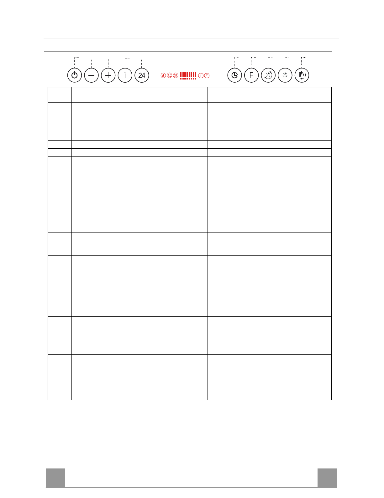
GR
559
ΧΡΗΣΗ
Πίνακας χειριστηρίων
Πλήκτρο
Λειτουργία Οθόνη
A Πόρτα κλειστή: Αν το πιέσετε για περίπου 1 δευτερό-
λεπτο, η πόρτα ανοίγει και το µοτέρ ανάβει στην τελευταία επιλεγµένη ταχύτητα.
Πόρτα ανοιχτή: Αν το πιέσετε για λίγο, ανάβει ή σβήνει το µοτέρ.
Εµφανίζει την επιλεγµένη ταχύτητα.
B Μειώνει την ταχύτητα λειτουργίας. Μειώνονται οι αναµµένες γραµµές.
C Αυξάνει την ταχύτητα λειτουργίας. Αυξάνονται οι αναµµένες γραµµές.
D Ενεργοποιείται µόνο µε την πόρτα ανοιχτή. Η ταχύτη-
τα αυτή ενεργοποιείται µε χρονοδιακόπτη 10 λεπτών.
Μετά την πάροδο του χρόνου αυτού το σύστηµα επα-
νέρχεται στην προηγούµενη επιλεγµένη ταχύτητα.
Κατάλληλη για µεγάλη παραγωγή ατµών από το µαγείρεµα.
Αναβοσβήνει I και οι γραµµές στην οθόνη είναι
όλες αναµµένες.
Απενεργοποιείται πιέζοντας το πλήκτρο.
E Ενεργοποιείται µόνο µε την πόρτα ανοιχτή, ανάβει το
µοτέρ σε µια ταχύτητα που επιτρέπει µια αναρρόφηση
100 m3/h.
Εµφανίζει την ένδειξη I και οι γραµµές στην
οθόνη από όλες αναµµένες αρχίζουν να σ βήνουν
µία µία τη φορά.
Απενεργοποιείται πιέζοντας το πλήκτρο.
F Ενεργοποιείται µε το µοτέρ αναµµένο, ενεργοποιεί το
αυτόµατο σβήσιµο του µοτέρ και του φωτισµού µε
καθυστέρηση 30’.
Εµφανίζει το σύµβολο του Ρολογιού που αναβο-
σβήνει.
Απενεργοποιείται πιέζοντας το πλήκτρο.
G Εκτελεί το Reset του συναγερµού κορεσµού των φίλ-
τρων πιέζοντας το πλήκτρο για περίπου 2 δευτερόλεπτα.
Μετά από 100 ώρες λειτουργίας εµφανίζει το
σύµβολο Σταγόνας επισηµαίνοντας τον κορεσµό
των µεταλλικών φίλτρων.
Μετά από 200 ώρες λειτουργίας εµφανίζει το C
επισηµαίνοντας τον κορεσµό των φίλτρων ενερ-
γού άνθρακα.
H Αλλάξει την ένταση του φωτισµού σε κάθε πίεση του
πλήκτρου το πολύ µέχρι 5 σκάλες κυκλικά.
I Πόρτα κλειστή: Αν το πιέσετε για περίπου 1 δευτερό-
λεπτο, η πόρτα ανοίγει και τα φώτα ανάβουν στη µέγιστη ένταση.
Πόρτα ανοιχτή: Αν το πιέσετε για λίγο, ανάβει ή σβήνει τα φώτα.
L Πόρτα κλειστή: Αν το πιέσετε για περίπου 1 δευτερό-
λεπτο, η πόρτα ανοίγει, το µοτέρ ανάβει στην τρίτη
ταχύτητα και τα φώτα ανάβουν στη µέγιστη ένταση.
Πόρτα ανοιχτή: Αν το πιέσετε για περίπου 1 δευτερόλεπτο, σβήνει τα πάντα, µοτέρ και φώτα, µηδενίζοντας
οποιαδήποτε λειτουργία και κλείνει την πόρτα.
Χειριστήριο κλειδώµατος πλήκτρων: είναι δυνατό να κλειδώσετε τα πλήκτρα, π.χ. για να καθαρίσετε το τζάµι, όταν το µοτέρ και τα φώτα του απορροφητήρα είναι σβηστά τόσο µε την πόρτα
ανοιχτή ή κλειστή.
Πιέζοντας για περίπου 5 δευτερόλεπτα το πλήκτρο F (Delay) µπορείτε να ενεργοποιήσ ετ ε ή απενεργοποιήσετ ε το κλείδωµα πλήκτρων που επιβεβαιώνεται πάντα µε ένα µπιπ και ένα γραφικό
στην µπάρα µοτέρ της οθόνης.
B
A
D
C
E
G
F
I
H
L
Page 60

GR
660
ΤΗΛΕΧΕΙΡΙΣΤΗΡΙΟ
Η συσκευή ελέγχεται και µε τηλεχειριστήριο που δέχεται αλκαλικές µπαταρίες ψευδαργύρου-άνθρακα 1,5 V
στάνταρ τύπου LR03-AAA.
• Μη βάζετε το τηλεχειριστήριο κοντά σε πηγές θερ-
µότητας.
• Μην πετάτε τις µπαταρίες στο περιβάλλον, αλλά µόνο στους ειδικούς κάδους.
Πίνακας χειριστηρίων τηλεχειριστηρίου
T1 Φως Πόρτα κλειστή: Η πόρτα ανοίγει και τα φώτα ανάβουν στη µέγιστη ένταση.
Πόρτα ανοιχτή: Ανάβει ή σβήνει τα φώτα.
T2 Φως Ρυθµίζει τα φώτα σε ενδιά µεση ένταση ή σβήνει τα φώτα (µόν ο µε την
Πλαφονιέρας πόρτα ανοιχτή).
T3 Μοτέρ Πόρτα κλειστή: Η πόρτα ανοίγει και το µοτέρ ανάβει στην τελευταία επι-
λεγµένη ταχύτητα.
Πόρτα ανοιχτή: Ανάβει ή σβήνει το µοτέρ.
Αν το πιέσετε για 2 δευτερόλεπτα:
Πόρτα κλειστή: Η πόρτα ανοίγει και το µοτέρ ανάβει στην τρίτη ταχύτητα
µε τα φώτα στη µέγιστη ένταση.
Πόρτα ανοιχτή: Σβήνει τα φώτα, το µοτέρ και κλείνει την πόρτα .
T4 Μειώ νει την ταχύτητα λειτουργίας σε κάθε σύντοµη πίεση.
Αν το πιέσετε για 2 δευτερόλεπτα:
Μειώνει την ένταση των φώτων.
T5 Αυξάνει την ταχύτητα λειτουργίας σε κάθε σύντοµη πίεση.
Αν το πιέσετε για 2 δευτερόλεπτα:
Αυξάνει την ένταση των φώτων.
T6 Έντονη Ενεργοποιεί / Απενεργοποιεί την έντονη ταχύτητα.
T7 Delay / 24h Ενεργοποιεί / Απενεργοποιεί τη λειτουργία καθυστέρησης.
Αν το πιέσετε για 2 δευτερόλεπτα:
Ενεργοποιεί / Απενεργοποιεί τη λειτουργία 24Η.
T1
T6
T2
T3
T4
T5
T7
Page 61

GR
661
ΣΥΝΤΗΡΗΣΗ
Μεταλλικά φίλτρα για λίπη
Μπορούν να πλυθούν και στο πλυντήριο πιάτων και απαιτούν πλύσιµο
όταν στην οθόνη εµφανίζεται το σύµβολο Σταγόνας ή τουλάχιστον κάθε
2 µήνες χρήσης ή συχνότερα σε περίπτωση ιδιαίτερα συχνής χρήσης.
Μηδενισµός του συναγερµού
• Πιέστε το πλήκτρο G για τουλάχιστον 2 δευτερόλεπτα.
Καθαρισµός φίλτρων
• Αν η πόρτα είναι κλειστή, ανοίξτε την πιέζοντας για περίπου 1
δευτερόλεπτο το πλήκτρο A (Βλ. ΧΡΗΣΗ).
• Βγάλτε τα φίλτρα ένα-ένα πιέζοντας προς το πίσω µέρος και
τραβώντας ταυτόχρονα προς τα κάτω.
• Πλύνετε τα φίλτρα χωρίς να τα στραβώσετε και αφήστε τα να
στεγνώσουν πριν τα τοποθετήσετε στη θέση τους. (Η
ενδεχόµενη αλλαγή χρώµατος της επιφάνειας του φίλτρου µε
την πάροδο του χρόνου, δεν επηρεάζει µε κανένα τρόπο την
απόδοσή τους.)
• Τοποθετήστε τα έτσι ώστε η λαβή να παραµείνει προς το
εξωτερικό µέρος.
Page 62

GR
662
Φίλτρο ενεργού άνθρακα για οσµές (Μοντέλο ανακύκλωσης)
∆εν µπορεί να πλυθεί και να αναγεννηθεί και πρέπει να αντικαθίσταται όταν στην οθόνη εµφανίζεται το σύµβολο C ή τουλάχιστον κάθε 4 µήνες. Η σήµανση του συναγερµού πρέπει να
έχει προηγουµένως ενεργοποιηθεί.
Ενεργοποίηση του συναγερµού
• Στους απορροφητήρες µοντέλο ανακύκλωσης, η σήµανση του συναγερµού κορεσµού φίλτρων ενεργοποιείται κατά την εγκατάσταση ή στη συνέχεια.
• Σβήστε τα φώτα και το µοτέρ αναρρόφησης.
• Πιέστε το πλήκτρο E για περίπου 5 δευτ. µέχρι να ανάψουν οι δύο τελευταίες γραµµές και
όλες οι τελείες της µπάρας µοτέρ στην οθόνη.
• Αφήστε το πλήκτρο E, το εικονίδιο του "Ρολογιού" αρχίζει να αναβοσβήνει.
• Εντός 3 δευτερολέπτων πιέστε το πλήκτρο D για την ενεργοποίηση / απενεργοποίηση των
φίλτρων ενεργού άνθρακα.
• Άναµµα του συµβόλου C - Συναγερµός κορεσµού φίλτρου ενεργού άνθρακα ΕΝΕΡΓΟ-
ΠΟΙΗΜΕΝΟΣ
• Σβήσιµο του συµβόλου C - Συναγερµός κορεσµού φίλτρου εν εργού άνθρακα ΑΠΕ-
ΝΕΡΓΟΠΟΙΗΜΕΝΟΣ
ΑΝΤΙΚΑΤΑΣΤΑΣΗ ΦΙΛΤ ΡΟ Υ ΕΝΕΡΓΟΥ ΑΝΘΡΑΚΑ
Μηδενισµός του συναγερµού
• Πιέστε το πλήκτρο G για τουλάχιστον 2 δευτερόλεπτα.
Αντικατάσταση φίλτρου
• Αν η πόρτα είναι κλειστή, ανοίξτε την πιέζοντας για περίπου 1 δευτερόλεπτο το πλήκτρο A (Βλ. ΧΡΗΣΗ).
• Βγάλτε τα φίλτρα για λίπη.
• Βγάλτε τα κορεσµένα φίλτρα ενεργού άνθρακα όπως στο
σχέδιο (A).
• Τοποθετήστε τα νέα φίλτρα όπως στο σχέδιο (B).
• Τοποθετήστε τα φίλτρα για λίπη.
A
B
Φωτισµός
ΑΝΤΙΚΑΤΑΣΤΑΣΗ ΛΑΜΠΤΗΡΩΝ
Λαµπτήρες αλογόνου των 20 W
• Βγάλτε το λαµπτήρα από τη βάση.
• Αντικαταστήστε τον µε νέο λαµπτήρα ίδιων χαρακτηριστικών,
έτσι ώστε να προσαρµόσουν σωστά τα δύο βύσµατα στις υποδοχές της βάσης.
Page 63

GR
663
Αντικατάσταση ασφάλειας
Η ασφάλεια επεµβαίνει µόνο στο µοτέρ που ελέγχει το
άνοιγµα και το κλείσιµο της πόρτας. Εποµένως σε περίπτωση που η ασφάλεια καεί µε την πόρτα κλειστή, θα
πρέπει να ξεµπλοκάρετε χειροκίνητα την πόρτα όπως
περιγράφεται παρακάτω:
• Βγάλτε το καπάκι που βρίσκεται στη γωνία επάνω
αριστερά.
• Με τη βοήθεια ενός κατσαβιδιού εξασκήστε µια πίεση στο µοχλό απεµπλοκής, έως ότου ανοίξει λίγο η
πόρτα επιτρέποντάς σας να την ανοίξετε χειροκίνητα.
• Αφού ανοίξετε εντελώς την πόρτα, αφαιρέστε τα µεταλλικά φίλτρα για λίπη όπως περιγράφεται στην
παράγραφο Καθαρισµός φίλτρων για λίπη.
• Η ασφάλεια βρίσκεται επάνω δεξιά, περιστρέψτε την
ασφαλειοθήκη όπως δείχνει η εικόνα και αντικαταστήστε την ασφάλεια µε µία ίδιων χαρακτηριστικών.
• Τοποθετήστε και πάλι την ασφαλειοθήκη και τα φίλτρα για λίπη και ελέγξτε αν λειτουργεί σωστά ο απορροφητήρας. Σε περίπτωση που ο απορροφητήρας
συνεχίσει να µη λειτουργεί, απευθυνθείτε στο εξουσιοδοτηµένο Σέρβις.
Αν η ασφάλεια καεί µε την πόρτα ανοικτή, αρκεί να
αφαιρέσετε τα φίλτρα για λίπη και να αντικαταστήσετε
την ασφάλεια.
Page 64

RU
664
СОВЕТЫ И РЕКОМЕНДАЦИИ
Настоящее руководство по эксплуатации составлено для разных моделей
прибора. Возможно, вы встретите в нем описание отдельных комплектующих, не относящихся к модели Вашего прибора.
УСТАНОВКА
• Производитель отклоняет всякую ответственность за повреждения, вызванные неправильной и несоответствующей правилам установкой.
• Проверить соответствие напряжения сети указанному на табличке, закрепленной внутри вытяжки.
• Для приборов класса I проверить, чтобы электрическая проводка в доме
обеспечивала правильное заземление.
• Соединить вытяжку с дымоходом трубкой диаметром, равным или больше 120 мм. Длина трубки должна быть как можно меньше.
• Не соединять вытяжку с выпускными трубами дымов от процессов горения (котлы, камины и проч.).
• В случае если в помещении используются как вытяжка, так и приборы, не
работающие на электроэнергии (например, газовые приборы), необходимо должным образом проветривать помещение. Если на кухне нет окна,
сделать отверстие наружу из помещения, чтобы через него поступал
свежий воздух.
ЭКСПЛУАТАЦИЯ
• Вытяжка спроектирована исключительно для бытового применения для
уничтожения запахов от готовки.
• Никогда не допускать несоответствующего пользования вытяжкой.
• Не оставлять открытое и сильное пламя под находящейся в работе вытяжкой.
• Обязательно регулировать пламя, чтобы оно не выходило за дно каст-
рюль.
• Следить за работой фритюрниц: сильно нагретое масло может воспла-
мениться.
• Не готовьте блюда фламбе под кухонной вытяжкой; опасность возникновения пожара.
• Запрещается пользоваться прибором людям (и детям) с ограниченными
психическими, сенсорными и умственными способностями, а также лицам, не обладающим опытом и необходимыми знаниями, без контроля и
предварительного обучения пользованием прибора со стороны ответственных за их безопасность лиц.
• Дети должны находиться под надзором взрослых и не играть с прибором.
УХОД
• Прежде чем приступать к любой операции по уходу, отсоединить вытяжку
от сети, вынув электрическую вилку или выключив главный выключатель.
• Производить тщательный и своевременный уход за фильтрами в рекомендуемые интервалы времени.
• Для уборки поверхностей вытяжки пользоваться влажной тряпкой и жидким нейтральным мылом.
Page 65

RU
665
ХАРАКТЕРИСТИКИ
Составные части
Поз. К-во Составные части изделия
1 1 Корпус вытяжки в комплекте с устройствами управ-
ления, системой освещения, вентилятором, фильтрами.
2.1 1 Верхняя часть дымохода
2.2 1 Нижняя часть дымохода
8 1 Регулируемая решетка выпуска воздуха
9 1 Переходный фланец 150-120
16 1 Фильтрующая крышка
Поз. К-во Детали для установки
7.2.1 2 Скобы крепления верхней части дымохода
11 7 Дюбели
11а 2 Дюбели SB 12/10
12а 7 Винты 4,2 х 44,4
12с 10 Винты 2,9 x 6,5
12e 2 Винты 2,9 х 9, 5
К-во Документация
1 Руководство по эксплуатации
1
16
12c
12d
8
9
11a
2.1
2.2
12c
12a
7.2.1 11
11
12a
11
12a
Page 66

RU
666
Габариты
Page 67

RU
667
УСТАНОВКА
Сверление отверстий в стене и крепление скоб
Провести на стене:
• вертикальную линию до потолка или до верхнего предела по центру участка, предназначенного для установки вытяжки;
• горизонтальную линию на высоте не менее 960 мм от варочной панели.
• Справа от базовой вертикальной линии и на расстоянии 292 мм от нее, отметить на горизонтальн ой линии точку (1).
• Повторить эту операцию с противоположенной стороны вертикальной линии и проверить, чтобы точки были на одн ом уровне.
• Аналогичным способом отметить базовую точку (2) на расстоянии 200 мм от вертикальной линии и на высоте 458 мм от варочной панели.
• Повторить эту операцию с противоположенной стороны вертикальной линии и проверить, чтобы точки были на одн ом уровне.
• Аналогичным способом отметить базовую точку (3) на вертикальной линии на высоте
743 мм от варочной панели.
• Высверлить отверстия ø 12 мм в обозначен ны х точках (1).
• Высверлить отверстия ø 8 мм в обозначенных точках (2) и (3).
• Вставить дюбели со скобой 11a в отверстия (1) и за тянуть винты.
• Вставить дюбель 11 в (2) и (3).
• Приложить скобу 7.2.1 к стене на расстоянии 1–2 мм от потолка или верхнего предела и
выровнять ее центр (пазы) по вертикальн ой линии.
• Отметить на стене центральную точку отверс тий скобы.
• Приложить скобу 7.2.1 к стене на расстоянии Х мм от предыдущей скобы (Х = высота
верхней части дымохода) и выровнять ее центр (пазы) по вертикальной линии.
• Отметить на стене центральную точку отверс тий скобы.
• Высверлить отверстия ø 8 мм в обозначенных точках.
• Вставить дюбели 11 в соответствующие отверстия.
• Закрепить скобы с помощью винтов 12а (4,2 x 44,4), поставляемых в комплекте с изделием.
11a
1
1
22
200
11
12a
11
12a
3
292 292
960
458
X
1÷2
7.2.1
368
200
743
Page 68

RU
668
Установка корпуса вытяжки
• Вставить два винта Vr скоб 11a в исходное положение (B).
• Повесить корпус вытяжки на 2 скобы 11a.
• Подключить вытяжку к сети электропитания через
двухполюсный выключатель с расстоянием между
разомкнутыми контактами не менее 3 мм.
• Нажать в течение 1 секунды клавишу "А" (См. параграф ИНСТРУКЦИИ ПО ЭКСПЛУАТАЦИИ),
чтобы открыть в ерхнюю панель.
• Снять жировые фильтры путем поворота соответствующих ручек.
• Изнутри корпуса вытяжки отрегулирова ть затяжку
винтов Vr, чтобы выставить его по уровню.
• Затянуть предохранительный винт 11.
• Установить жировые фильтры и закрыть верхнюю
панель, поддерживая клавишу "L" нажатой в течение 1 секунды (См. параграф ИНСТРУКЦИИ ПО
ЭКСПЛУАТАЦИИ).
• Отсоединить вытяжку от сети электропитания.
Внимание: Если створка, во время открытия или за-
крытия, встречает какое-нибудь препятствие, то она
останавливается. После удаления препятствия и нажатия клавиши створка открывается.
(B)
L
A
11a
Vr
11
Соединения
ВЫПУСК ВОЗДУХА ИЗ ВСАСЫВАЮЩЕЙ ВЫТЯЖКИ
Для установки всасывающей вытяжки соединить ее
с выпускной трубой жесткой или гибкой трубкой
диаметром 150 или 120 мм, тип которой может выбрать монтажник.
• Для соединения трубкой Ø 120 мм вставить переходный
фланец 9 в выпускное отверстие корпуса вытяжки.
• Закрепить трубку соответствующими трубными
зажимами. Необходимый крепежный материал не
входит в комплект.
• Вынуть фильтры от запахов на активном угле.
ø 150
9
ø 120
Page 69
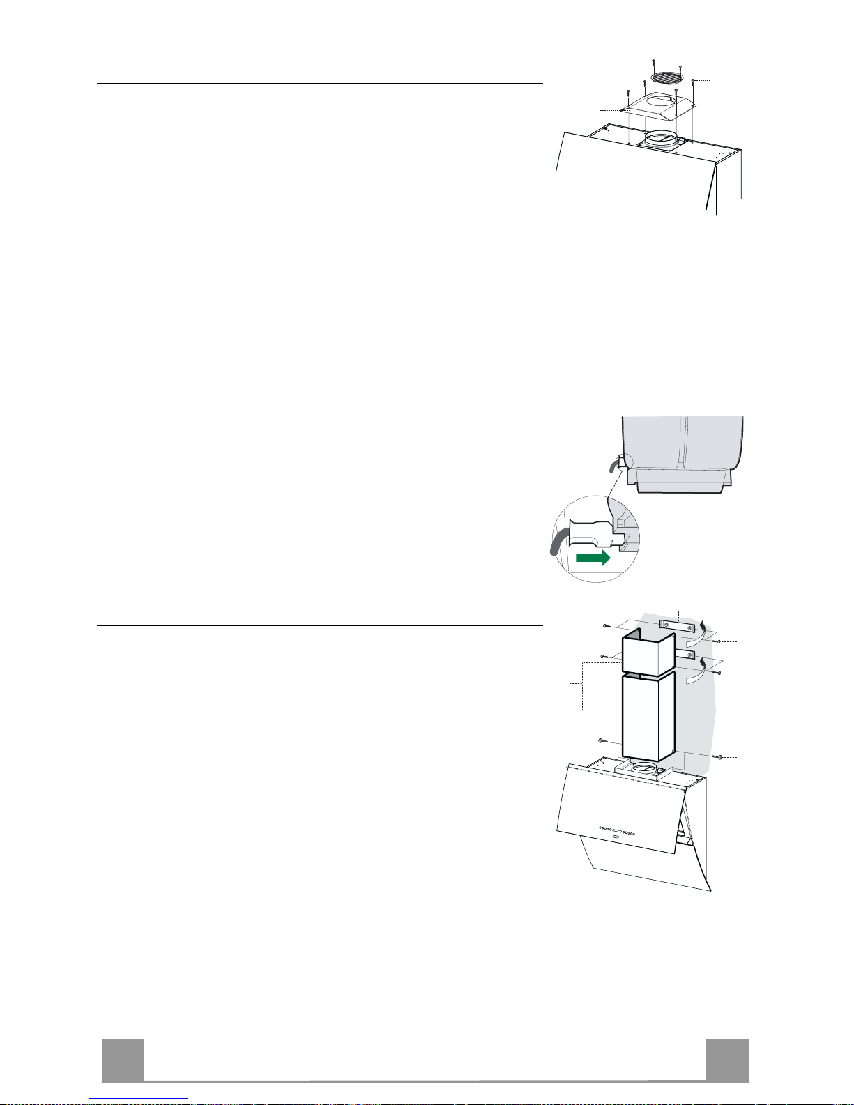
RU
669
ВЫПУСК ВОЗДУХА ИЗ ФИЛЬТРУЮЩЕЙ ВЫТЯЖКИ
Для установки исполнения с режимом рециркуляции (с
фильтрацией) необходимо установить дополнительный комплект картриджа с угольным фильтром.
• Снимите крепежный уголок дымохода
• Закрепите над отверстием для выпуска воздуха фильтрующее покрытие, пользуясь 4 винтами 12c (2,9 x 6,5).
• Закрепите направленную решетку 8 над отверстием для
выпуска очищенного воздуха 2 прилагаемыми винтами
12d (2,9 x 9,5).
16
12c
12d
8
ПОДКЛЮЧЕНИЕ ВЫТЯЖКИ К ЭЛЕКТРИЧЕСКОЙ СЕТИ
• Вновь подключить вытяжку к сети электропитания.
• Нажать в течение 2 секунды клавишу "А" (См. параграф
Инструкции по эксплуатации), чтобы открыть верхнюю
панель.
• Снять жировые фильтры (См. параграф "Уход") и убедиться, что разъем шнура питания правильно вставлен в розетку вытяжного вентилятора.
Установка дымохода
Верхний дымоход
• Слегка развести две боковые кромки дымохода, зацепить
их за скобы 7.2.1 и вновь свести их до упора.
• Закрепить дымоход сбоку 4 входящими в комплект винтами 12c (2,9 x 9,5).
Нижний дымоход
• Слегка развести две боковые кромки дымохода, зацепить
их между верхним дымоходом и стеной и вновь свести их
до упора.
• Закрепить нижнюю часть дымохода сбоку к корпусу вытяжки входящими в комплект 2 винтами 12c (2,9 x 9,5).
12c
2.1
2.2
2
7.2.1
12c
Page 70
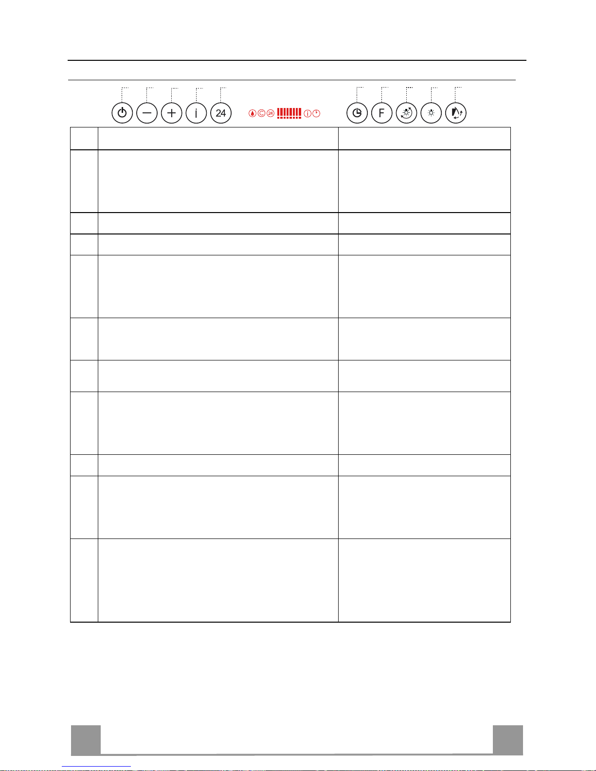
RU
770
ЭКСПЛУАТАЦИЯ
Панель управления
Клав
иша
Функция Показание дисплея
A
При закрытой створке: Нажатие клавиши в течение 1
секунды вызывает открытие створки и включение
двигателя на последнюю заданную скорость.
При открытой створке: Кратковременное нажатие
клавиши вызывае т включение или выключение двигателя.
Заданная скорость двигателя
B
Понижение рабо чей скорости Уменьшение числа отображенных
сегментов.
C
Повышение раб очей скорости Увеличение числа отображенных
сегментов.
D
Включается только при открытой створке. При выбранной с помощью этой кл авиши скорости вытяжка
работает в течение 10 минут, по истечении которых
она переключается на ранее заданную скорость. Используется при особенно сильном выделении дыма
во время приготовления пищи.
Мигает I; на дисплее отображены
все сегме нт ы.
Выключается нажат ие м клавиши.
Е
Включается только при открытой створке. Вызывает
включение двигателя на скорость, обеспечивающую
всасывание 100 куб.м/час воздуха.
Высвечивается цифра 24; на дисплее
отображены все сегменты, которые
по очереди исчезают.
Выключается нажат ие м клавиши.
F
Используется при включенном двигателе для выбора
автоматического выключения двигателя и освещения
с выдерж кой времени на 30 минут.
Мигает симво л часов
Выключается нажат ие м клавиши.
G
Нажатием этой клавиши в течение около 2 секунд
осуществляется сброс аварийной сигнализации по
насыщению фильтров.
После 100 часов работы появляется
символ капли, предупреждающий о
насыщении металлических фильтров
После 200 часов работы появляется
буква С, предупреждающая о насыщении угольных фильтров
Н
Изменение интенсивности освещения при каждом
нажатии клавиши до макс. 5 уровней.
I
При закрытой створке: Нажатие клавиши в течение 1
секунды вызывает открытие створки и включение
освещения при максимальной интенсивности.
При открытой створке: Кратковременное нажатие
клавиши вызывает включение или выключение освещения.
L
При закрытой створке: Нажатие клавиши в течение 1
секунды вызывает открытие створки, включение
двигателя на 3-ю скорость и освещения при максимальной интенсивности.
При открытой створке: Нажатие клавиши в течение 1
секунды вызывает выключение двигателя и освещения, закрытие створки, а также аннулирование любой активной функции.
Блокир овк а клавиатуры: Система позвол яет блоки рова ть клавиатуру (например, при очистке
стекла) при открытой или закрытой створке, если двигатель и освещение вытяжки находятся в
выключенном состоянии.
Блокир овк а или разблокировка клавиатуры выполняются нажатием клавиши F (Выдержка времени) в течение 5 секунд и подтверждаются зв у ковы м сигналом и движением полосы дисплея.
B
A
D
C
E
G
F
I
H
L
Page 71

RU
771
ПУЛЬТ ДИСТАНЦИОННОГО УПРАВЛЕНИЯ
Данным прибором можно управлять пультом дистанционного управления на щелочных батарейках с угольным элементом 1,5 В стандартного типа LR 03-AAA .
• Не оставлять пульт вблизи от источников тепла.
• Не выбрасывать батарейки вместе с обычным му-
сором, складывать их в специальные сборные емкости.
Переносный пульт управления
T1 Рабочее При закрытой створке: Открытие створки и включение освещения
освещение при максимальной интенсивности.
При открытой створке: Включение или выключе ние освещения.
T2 Вспомог ате льное Включение осве щения при средней интенсивности или выкл ючение
освещение освещения (только при открытой створке).
T3 Двигатель При закрытой створке: Открытие створки и включение двигателя на послед-
нюю заданную скорость.
При открытой створке: Включение или выключе ние двигателя.
Нажатие клавиши в течение 2 секунд:
При закрытой створке: Открытие створки, включение двигателя на третью
скорость и освещения при максимальной интенсивности.
При открытой створке: Выключение освещения, двигателя и закрытие створ-
ки.
T4 Понижение рабо чей скорости при каждом кратковременном нажатии.
Нажатие клавиши в течение 2 секунд:
Уменьшение интенсивности освещения.
T5 Повышение раб очей скорости при каждом кратковременном нажатии.
Нажатие клавиши в течение 2 секунд:
Увеличение интенсивно сти освещения.
T6 Повыше нная Включение/выключение повышенной скорости.
скорость
T7 Выдержка / 24 ч Активация/дезактивация функции выдержки времени.
Нажатие клавиши в течение 2 секунд:
Активация/дезактивация функции 24 Ч.
T1
T6
T2
T3
T4
T5
T7
Page 72

RU
772
УХОД
Металлические жировые фильтры
Фильтры можно мыть в посудомоечной машине. Мойка необходимо осуществлять не реже раза в два месяца работы
или чаще в случае особенно интенсивного их применения.
Сброс аварийной сигнализации
• Нажать клавишу G в течение не менее 2 секунд.
Очистка фильтров
• Если створка закрыта, откройте ее нажатием клавиши А в
течение около 1 секунды (См. руководство по эксплуатации).
• Вынуть фильтры по очереди. Для этого прижать их к задней стороне вытяжки и одновременно потянуть вниз.
• Осторожно помыть фильтры, чтобы они не согнулись, и
перед установкой дать им просохнуть. (Появляющееся со
временем изменение цвета поверхности фильтра никоим
образом влияет на эффективность фильтрации)
• Поставить фильтры на место так, чтобы ручка находилась
с видной наружной стороны.
Page 73

RU
773
Угольные фильтры, предотвращающие появление запахов (исполнение с режи-
мом рециркуляции)
Эти фильтры не допускают мойки и не могут быть восстановлены. Необходимо выполнять их замену при появлении на дисплее символа С или не реже одного раза в 4 месяца. Соответствующая сигнализация включается заранее.
Включение сигнализации
• В вытяжках исполнения с режимом рециркуляции включение сигнализации насыщения фильтров выполняется в момент установки или после этого.
• Выключите освещение и двигатель, обеспечивающий вытяжку.
• Нажмите кнопку Е примерно на 5 секунд, до тех пор пока на дисплее не загорятся
два последних сегмента, а также вся пунктирная линия на полоске двигателя.
• Освободите кнопку Е, при этом начнет мигать значок часов.
• В течение 3 секунд нажмите кнопку D для включения/выключения сигнализации насыщения угольных фильтров, предотвращающих появление запахов.
• Символ С включен – Сигнализация насыщения фильтра ВКЛЮЧЕНА
• Символ С выключен – Сигнализация насыщения фильтра ВЫКЛЮЧЕНА
ЗАМЕНА ФИЛЬТРА ОТ ЗАПАХОВ НА АКТИВНОМ УГЛЕ
Сброс аварийной сигнализации
• Нажать клавишу G в течение не менее 2 секунд.
Замена фильтра
• Если створка закрыта, откройте ее нажатием клавиши А в
течение около 1 секунды (См. руководство по эксплуатации).
• Снять жировые фильтры.
• Вынуть насыщенные фильтры на активированном угле,
как указано на рисунке (А).
• Установить новые фильтры, как указано на рисунке (В).
• Поставить на место жировые фильтры.
A
B
Освещение
ЗАМЕНА ЛАМП
Галогенные лампы 20 Вт.
• Вынуть из патрона лампу.
• Заменить ее на новую с такими же характеристиками; пра-
вильно вставить два штыревых контакта в гнездо лампового патрона.
Page 74

RU
774
Замена предохранителя
Предохранитель воздействует только на движок,
управляющий раскрытием и закрытием створки
.
Поэтому в случае его повреждения при закрытой
створке необходимо разблокировать ее, как описано
ниже:
• Снимите крышку в верхнем левом углу.
• Прямой отверткой нажмите на блокирующий ры-
чаг, чтобы створка приоткрылась, и можно было
полностью открыть ее рукой.
• Снимите металлические противожировые фильтры в соответствии с указаниями раздела об очистке противожировых фильтров.
• Предохранитель находится вверху справа; поверните, как показано, плавкую вставку и замените
предохранитель на новый с такими же характеристиками.
• Поставьте на место плавкую вставку, противожировые фильтры и проверьте действие вытяжки.
Если створка все еще не открывается, обратитесь
к уполномоченному техническому специалисту.
При обнаружении поломки предохранителя при открытой створке достаточно просто снять противожировые фильтры и заменить предохранитель.
Page 75

SA
775
تﺎﺣاﺮﺘﻗا و تادﺎﺷرا
تﻼﻳدﻮﻣ ةﺪﻋ ﻊﻣ ﻪﻟﺎﻤﻌﺘﺳﻻ ﻢﻤﺻ ﺪﻗ اﺬه تادﺎﺷرﻹا ﺐﻴﺘآ نإ.
تاﺰﻴﻤﻣو ﻞﻴﺻﺎﻔﺗ ﻪﻴﻓ ﺪﺠﺗ ﺪﻗو ﻪﺋاﺮﺸﺑ ﺖﻤﻗ يﺬﻟا زﺎﻬﺠﻟا ﺺﺨﺗﻻ.
ﺐﻴآﺮﺘﻟا:-
• وا رﺮﺿ يا ﻦﻋ لﻮﺌﺴﻣ ﺮﻴﻏ ﻊﻨﺼﻤﻟا تﺎﻤﻴﻠﻌﺗ عﺎﺒﺗا مﺪﻋ ﻦﻋ ﺞﺗﺎﻧ ﻒﻠﺗ
ﺐﻴآﺮﺘﻟا .
• ةدﻮﺟﻮﻤﻟا تاﺪﺣﻮﻟا دﺪﻌﻟ ﺔﻘﺑﺎﻄﻣ ﺔﻴﺴﻴﺋﺮﻟا ﺖﻟﻮﻔﻟا تاﺪﺣو دﺪﻋ نا ﻦﻣ ﺪآﺎﺗ
طﺎﻔﺸﻟا ﻞﺧاد ﺔﻴﺳﺎﻴﻘﻟا تﺎﻔﺻاﻮﻤﻟا ﺔﺣﻮﻟ ﻲﻠﻋ .
• يﻮﺘﺴﻤﻟا ةﺰﻬﺟﻼﻟ ﺔﺒﺴﻨﻟﺎﺑ)I ( ﺔﻴﺴﻴﺋﺮﻟا ﺔﻗﺎﻄﻟا تاﺪﺣو ﻊﻴﻤﺟ ﺔﻴﻄﻐﺗ ﻦﻣ ﺪآﺎﺗ
ﻂﺋﺎﺤﻟا ﻞﺧاد .
• ﻤﻟﺎﺑ طﺎﻔﺸﻟا ﻞﻴﺻﻮﺘﺑ ﻢﻗ لﻮﻄﺑ ةرﻮﺳﺎﻣ لﻼﺧ ﻦﻣ ﺔﻨﺧﺪ120 نﻮﻜﺗ نا ﻲﻠﻋ ﻢﺳ
ﺔﻨﻜﻤﻣ ﺔﺟرد ﻲﺼﻗﻻ ةرﻮﺳﺎﻤﻟا لﻮﻃ ﻞﻴﻠﻘﺗ ةﺎﻋاﺮﻣ ﻊﻣ .
• ﻊﻣ مﺪﺨﺘﺴﺗ ﻲﺘﻟا ﻞﺜﻣ يﺮﺧا ﻦﺧاﺪﻣ يﺎﺑ طﺎﻔﺸﻟا ﻞﻴﺻﻮﺗ ﺐﺠﻳ ﻻ ) نﺎﺨﺳ
ﺔﺌﻓﺪﻤﻟا وا ﻩﺎﻴﻤﻟا ..... ﺦﻟا . (
• ﻞﺜﻣ ﺔﻴﺋﺎﺑاﺮﻬآ ﺮﻴﻏ يﺮﺧا ةﺰﻬﺣا دﻮﺟو ﻲﻓ ﻞﻤﻌﻳ طﺎﻔﺸﻟا نﺎآ اذا ) ةﺰﻬﺟا
ﺗﻮﺒﻟا زﺎﻐﻟﺎﺑ ﻞﻤﻌﺗ ﻲﺘﻟا زﺎﺟﺎ ( ﺔﻳﻮﻬﺘﻟا ﻦﻣ ﺔﻴﻓﺎآ ﺔﺟرد دﻮﺟو نﺎﻤﺿ ﺐﺠﻳ
زﺎﻐﻟا ﺔﺤﺋار رﺎﺸﺘﻧا ﻊﻨﻤﻟ ﻚﻟذو ﺔﻓﺮﻐﻟا ﻞﺧاد . ﺔﻓﺮﻐﻟا ﻞﺧاد نﻮﻜﻳ نا ﺐﺠﻳ اﺬﻟ
ﻒﻴﻈﻧ ءاﻮه لﻮﺧد نﺎﻤﻀﻟ ﺮﺷﺎﺒﻣ ﺔﻳﻮﻬﺗ ﺬﻔﻨﻣ .
ماﺪﺨﺘﺳﻻا:-
• ﺦﺒﻄﻤﻟا ﻦﻣ ﻲﻬﻄﻟا ةﺮﺨﺑا و ﺢﺋاور دﺮﻄﻟ ﻲﻟﺰﻨﻤﻟا ماﺪﺨﺘﺳﻼﻟا ﻢﻤﺼﻣ طﺎﻔﺸﻟا .
• ﺪﻋ ﺎﻬﻠﺟا ﻦﻣ ﻢﻤﺻ ﻲﺘﻟا ﺮﻴﻏ يﺮﺧا ضاﺮﻏا يﻻ طﺎﻔﺸﻟا ماﺪﺨﺘﺳا م .
• ﻲﻬﻄﻟا ﺔﻴﻠﻤﻋ ءﺎﻨﺛا طﺎﻔﺸﻟا ﻞﻔﺳا ﺔﻳرﺎﻋ زﺎﺟﺎﺗﻮﺒﻟا ﺔﻠﻌﺷ كﺮﺗ مﺪﻋ .
• ﺪآﺎﺘﻟا ﻊﻣ ءﺎﻧﻻا ةﺪﻋﺎﻗ ﻒﺼﺘﻨﻤﻟ ةﺮﺷﺎﺒﻣ ﻪﺟﻮﻣ نﻮﻜﺗ ﻲآ ﺔﻠﻌﺸﻟا ﻂﺒﺿ ةﺎﻋﺮﻣ
ءﺎﻧﻻا ةﺪﻋﺎﻗ فاﻮﺣ ﻲﻟا رﺎﻨﻟا لﻮﺻو مﺪﻋ ﻦﻣ .
• ﻊﺿو ﺐﺠﻳ ﺔﻴﻨهد داﻮﻣ ﻲﻬﻃ ﺪﻨﻋ ءﺎﻨﺛا ةﺮﻤﺘﺴﻤﻟا ﺔﺒﻗاﺮﻤﻟا ﺖﺤﺗ ﻲﻬﻄﻟا ءﺎﻧا
ﻲﻋ ﺖﻳﺰﻟا تاﺮﺘﻗ ﻖﻓﺪﺗ ﻦﻜﻤﻤﻟا ﻦﻣ ﺚﻴﺣ ﺔﻴﻟﺎﻋ ةراﺮﺣ ﺔﺟرد ﺖﺤﺗ ﻲﻠﻘﻟا
ﺔﻠﻌﺸﻟا .
• ﺔﻘﻳﺮﻄﺑ تﻻﻮآﺄﻤﻟا ﺮﻴﻀﺤﺘﺑ مﻮﻘﺗ ﻻ)ﻪﻴﺒﻣﻼﻔﻟا ( ﺪﻘﻓ ؛ﺦﺒﻄﻤﻟا ﺔﻨﺧﺪﻣ ﻞﻔﺳأ
ﻖﻳﺮﺣ ثﺪﺤﻳ
،ﺔﻴﺴﻔﻧ ﻞآﺎﺸﻣ نﻮﻜﻠﻤﻳ صﺎﺨﺷأ ﻞﺒﻗ ﻦﻣ زﺎﻬﺠﻟا اﺬه لﺎﻤﻌﺘﺳا مﺪﻋ ﺐﺠﻳ
ﻘﻋ ﻦﻳﺮﺻﺎﻗ ﻦﻴﻗﺎﻌﻣ وأ ًﺎ ﻴ ﻠ)لﺎﻔﻃﻷا ﻢﻬﻴﻓ ﺎﻤﺑ( نﻮﻜﻠﺘﻤﻳ ﻻ صﺎﺨﺷأ ﻞﺒﻗ ﻦﻣ وأ ،
صﺎﺨﺷأ ﻞﺒﻗ ﻦﻣ فاﺮﺷإ ﺎﻬﻴﻓ نﻮﻜﻳ ﻲﺘﻟا تﻻﺎﺤﻟا ﻲﻓ ﻻإ ،كاردﻹا وأ ةﺮﺒﺨﻟا
ﻢﻬﺘﻣﻼﺳ ﻰﻠﻋ ﻦﻴﺼﻳﺮﺣو ﻦﻴآرﺪﻣ.
• ﻢﻬﻠﺒﻗ ﻦﻣ ﺚﺒﻌﻟا وأ ﺐﻌﻠﻟا مﺪﻋ ﻦﻣ ﺪآﺄﺘﻟاو لﺎﻔﻃﻷا ﻰﻠﻋ فاﺮﺷﻹا ﺐﺠﻳ
زﺎﻬﺠﻟﺎﺑ.
ﺔﻧﺎﻴﺼﻟا:-
• ﻬﺠﻟا ﺔﺸﻴﻓ عﺰﻧا ﺔﻴﻠﻤﻋ ﻦﻣ عﻮﻧ يا ءاﺮﺟا ﻞﺒﻗ ﻲﺑﺮﻬﻜﻟا رﺎﻴﺘﻟا رﺪﺼﻣ ﻦﻣ زﺎ
ﺔﻧﺎﻴﺼﻟا .
• ماﺪﺨﺘﺳﻻا ﺔﻴﺣﻼﺻ ةﺮﺘﻓ ءﺎﻬﺘﻧا ﺪﻌﺑ ﺮﺗﻼﻔﻟا لﺪﺒﺘﺳا وا ﻒﻈﻧ .
• ﻲﻟﺰﻨﻤﻟا ﻒﻴﻈﻨﺘﻟا ﻞﺋﺎﺳ ﻊﻣ ﺔﺒﻃﺮﻣ شﺎﻤﻗ ﺔﻌﻄﻘﺑ طﺎﻔﺸﻟا ﻒﻴﻈﻨﺗ ﻢﺘﻳ .
Page 76
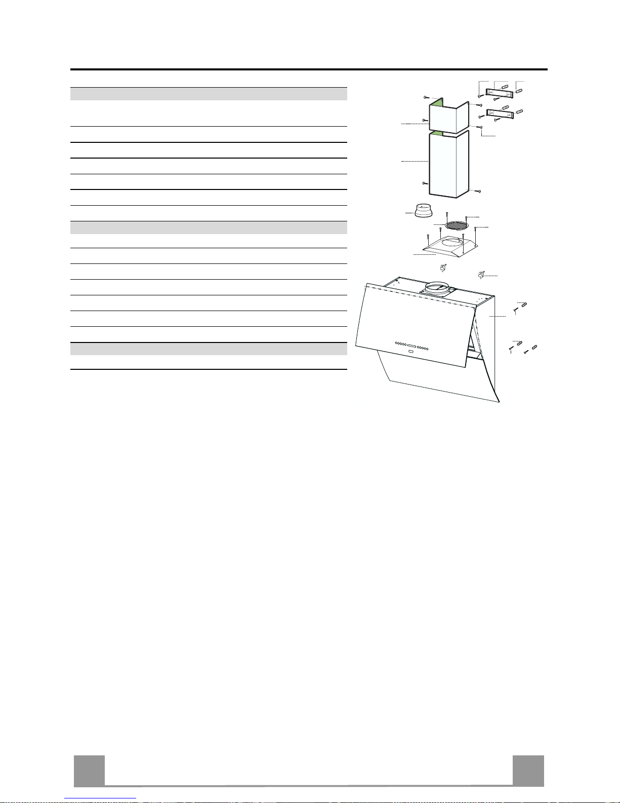
SA
776
ﺺﺋﺎﺼﺨﻟا
تﺎﻧﻮﻜﻤﻟا
دﻮﻜﻟا دﺪﻌﻟا ﺞﺘﻨﻤﻟا تﺎﻧﻮﻜﻣ
1 1 و ةءﺎﺿﻻا و ﻢﻜﺤﺘﻟا ةﺪﺣو ﻊﻣ طﺎﻔﺸﻟا زﺎﻬﺟ
ﺮﺗﻼﻔﻟا و ﺔﺣوﺮﻤﻟا ةﺪﺣ
1.2 1 يﻮﻠﻌﻟا ﺔﻨﺧﺪﻤﻟا ءﺰﺟ
2.2 1 ﻲﻠﻔﺴﻟا ﺔﻨﺧﺪﻤﻟا ءﺰﺟ
8 1 ءاﻮﻬﻟا جﺮﺨﻣ ﺔﻜﺒﺷ
9 1 يﺮﻐﺼﻟا ﺔﻓﺎﺤﻟاØ 120-150
16 1 ﻊﻳزﻮﺘﻟا ةدﺎﻋا جﺮﺨﻣ ءﺎﻄﻏ
دﻮﻜﻟا دﺪﻌﻟا ﺐﻴآﺮﺘﻟا تﺎﻧﻮﻜﻣ
1.2.7 2 ا ءﺰﺠﻟا ﺐﻴآﺮﺗ ﻞﻣﺎﺣ ﺔﻨﺧﺪﻤﻟا ﻦﻣ يﻮﻠﻌﻟ
11 7 ﺔﺒﻃ
11a 2 ﺔﺒﻃ12/10
12a 7 ﺮﻴﻣﺎﺴﻣ4.2 × 44.4
12c 10 ﺮﻴﻣﺎﺴﻣ2.9 × 6.5
12e 2 ﺮﻴﻣﺎﺴﻣ2.9 × 9.5
دﺪﻌﻟا تاﺪﻨﺘﺴﻤﻟا
1 تادﺎﺷرﻻا ﺐﻴﺘآ
1
16
12c
12d
8
9
11a
2.1
2.2
12c
12a
7.2.1 11
11
12a
11
12a
Page 77

SA
777
ﺔﻴﺳﺎﻴﻘﻟا دﺎﻌﺑﻻا
Page 78
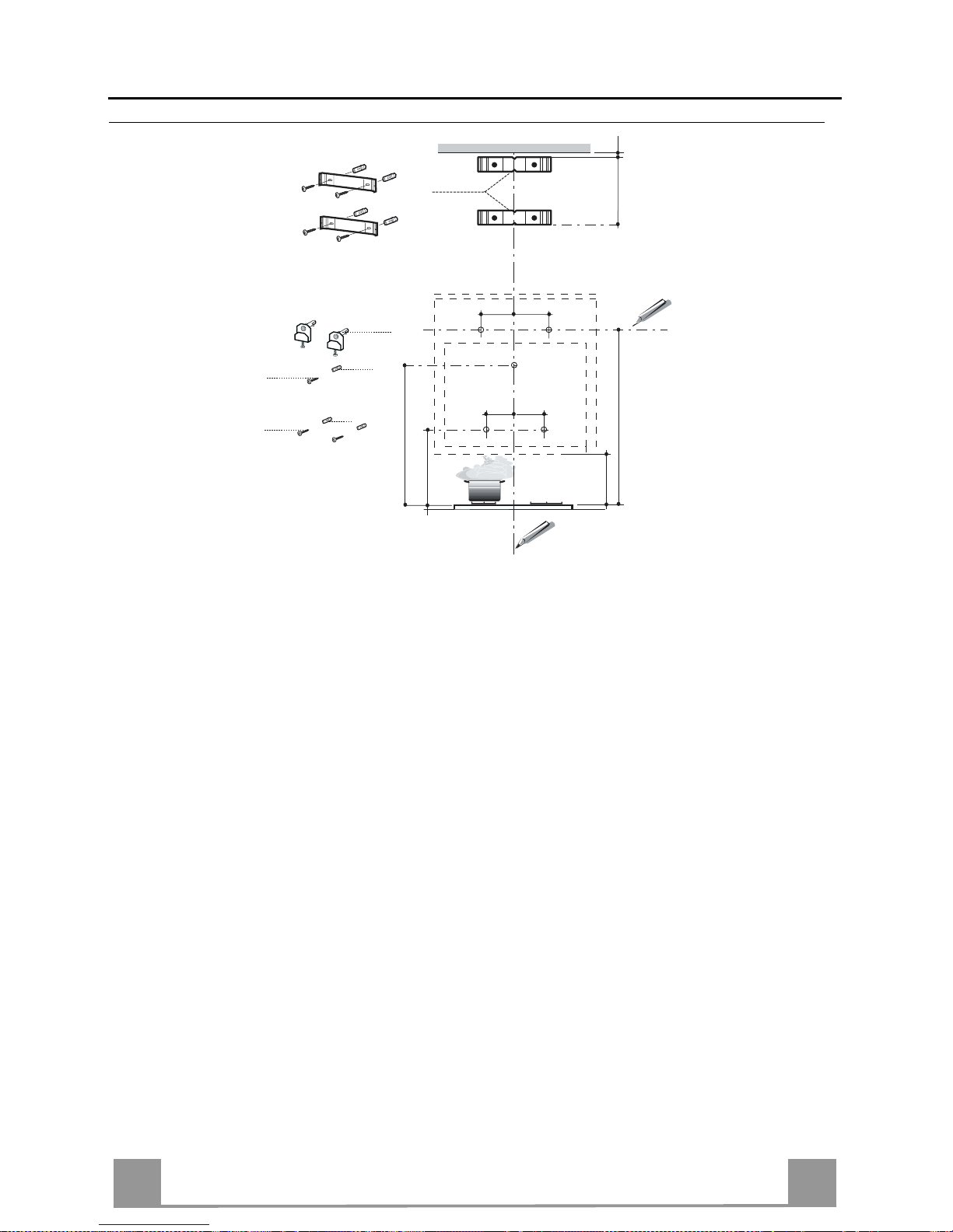
SA
778
ﺐﻴآﺮﺘﻟا
ﻞﻣﺎﺤﻟا ﺐﻴآﺮﺗو ﻂﺋﺎﺤﻟا ﺐﻘﺛ
ﺔﻤﺳﺮﻟا ﺮﻴﺸﺗ ﺎﻤآ ﺔﻴﻟﺎﺘﻟا تاﻮﻄﺨﻟا ﻊﺒﺗا ﻲﻟوﻻا ةﻮﻄﺨﻟا:-
• طﺎﻔﺸﻟا ﺐﻴآﺮﺗ ﺔﻘﻄﻨﻣ ﻒﺼﺘﻨﻤﺑ ﻢﻟذو يﻮﻠﻌﻟا ﺪﺤﻟا ﻲﻟا وا ﻒﻘﺴﻟا ﻲﺘﺣ ﻲﺳار ﻂﺧ ﻞﻤﻌﺑ ﻢﻗ
• ﺔﻓﺎﺴﻣ ﻲﻠﻋ ﻲﻘﻓا ﻂﺨﺑ ﻢﻗ60 ﻲﻬﻄﻟا زﺎﻬﺟ ﺢﻄﺳ قﻮﻓ ﻲﻧدا ﺪﺤآ ﻢﻣ
• ﻢﻗر ﺔﻄﻘﻨﻟا ﺪﻨﻋ ﺔﻣﻼﻋ ﻊﺿﻮﺑ ﻢﻗ)1 ( ﺪﻌﺑ ﻲﻠﻋو ﻲﻘﻓﻻا ﻂﺨﻟا ﻲﻠﻋ292 ﻲﺳاﺮﻟا ﻂﺨﻟا ﻦﻴﻤﻳ ﻦﻣ ﻢﻣ
• ﺪﺣاو يﻮﺘﺴﻣ ﻲﻓ ﻦﻴﺘﻣﻼﻌﻟا ﻼآ نا ﻦﻣ ﺪآﺎﺗو ﺮﺧﻻا ﺐﻧﺎﺠﻟا ﻲﻠﻋ يﺮﺧا ةﺮﻣ ﺔﻴﻠﻤﻌﻟا ﺲﻔﻧ رﺮآ
• ﻢﻗر ﺔﻄﻘﻨﻟا ﺪﻨﻋ ﺔﻣﻼﻋ ﻊﺿﻮﺑ ﻢﻗ)2 ( ﺔﻓﺎﺴﻣ ﻲﻠﻋ ﻢﺳﺮﻟﺎﺑ رﺎﺸﻣ ﻮه ﺎﻤآ200 و ﻲﺳاﺮﻟا ﻂﺨﻟا ﻦﻣ ﻢﻣ458 ﺢﻄﺳ قﻮﻓ ﻢﻣ
ﻲﻬﻄﻟا زﺎﻬﺟ
• ﻲﻠﻋ يﺮﺧا ةﺮﻣ ﺔﻴﻠﻤﻌﻟا ﺲﻔﻧ رﺮآ ﺪﺣاو يﻮﺘﺴﻣ ﻲﻓ ﻦﻴﺘﻣﻼﻌﻟا ﻼآ نا ﺪﻜﺗو ﺮﺧﻻا ﺐﻧﺎﺠﻟا .
• ﻢﻗر ﺔﻄﻘﻨﻟا ﺪﻨﻋ ﺔﻣﻼﻋ ﻊﺿ)3 ( ﺔﻓﺎﺴﻣ ﻲﻠﻋ743 ﻲﺳاﺮﻟا ﻂﺨﻟا ﻲﻠﻋو ﻲﻬﻄﻟا زﺎﻬﺟ ﺢﻄﺳ قﻮﻓ ﻢﻣ .
• ﻢﻗر ﺔﻄﻘﻨﻟا نﺎﻜﻣ ﺐﻘﺗا)1 ( راﺪﺟ ﺔﺸﻳر ماﺪﺨﺘﺳﺎﺑ ﻞﺒﻗ ﻦﻣ ﺎﻬﻳﺪﺤﺗ ﻢﺗ ﻲﺘﻟاØ 12 ﻢﻣ
• ﻢﻗر ﺔﻄﻘﻨﻟا ﻦﻣ ﻼآ نﺎﻜﻣ ﺐﻘﺛا)2 ( ﻢﻗرو)3 ( راﺪﺟ ﺔﺸﻳر ماﺪﺨﺘﺳﺎﺑØ 8 ﻢﻣ
• ﻞﻣﺎﺤﻟا ﺔﺒﻃ ﻞﺧدا11a ﻢﻗر ﺔﺤﺘﻔﻟا ﻞﺧاد )1 ( ﺮﻴﻣﺎﺴﻤﻟا ﻂﺑﺮﺑ ﻢﻗ ﻢﺛ .
• ﺔﺒﻄﻟا ﻞﺧدا11 ﻢﻗر ﺔﺤﺘﻔﻟا ﻦﻣ ﻼآ ﻞﺧاد )2 ( ﻢﻗرو)3 (
• ﻞﻣﺎﺤﻟا ﻊﺿ1.2.7 ﺔﻓﺎﺴﻣ ﻲﻠﻋ ﻂﺋﺎﺤﻟا ﻲﻠﻋ 1-2 ﻲﺳاﺮﻟا ﻂﺨﻟا ﻒﺼﺘﻨﻤﺑ ﻚﻟذو يﻮﻠﻌﻟا ﺪﺤﻟا ﻦﻣ وا ﻒﻘﺴﻟا ﻦﻣ ﻢﻣ
• ﺔﻣﻼﻋ ﻊﺿﻮﺑ ﻢﻗ ﻂﺋﺎﺤﻟا ﻲﻠﻋ ﻞﻣﺎﺤﻟا ﺐﻴآﺮﺗ تﺎﺤﺘﻓ ﻒﺼﺘﻨﻤﺑ ﻲﻠﻋ
• ﻞﻣﺎﺤﻟا ﻊﺿ1.2.7 ﺔﻓﺎﺴﻣ ﻲﻠﻋ ﻂﺋﺎﺤﻟا ﻲﻠﻋ X لوﻻا ﻞﻣﺎﺤﻟا ﺪﻌﺑ ﻢﻣ )X = ﺔﻨﺧﺪﻤﻟا ﻦﻣ يﻮﻠﻌﻟا ءﺰﺠﻟا عﺎﻔﺗرا ( ﻚﻟذو
ﻲﺳاﺮﻟا ﻂﺨﻟا ﻒﺼﺘﻨﻤﺑ
• ﻂﺋﺎﺤﻟا ﻲﻠﻋ ﻞﻣﺎﺤﻟا ﺐﻴآﺮﺗ تﺎﺤﺘﻓ ﻒﺼﺘﻨﻤﺑ ﺔﻣﻼﻋ ﻊﺿﻮﺑ ﻢﻗ .
• ﻳﺪﺤﺗ ﻢﺗ ﻲﺘﻟا تﺎﺤﺘﻔﻟا نﺎﻜﻣ ﺐﻘﺛا راﺪﺟ ﺔﺸﻳر ماﺪﺨﺘﺳﺎﺑ ﻞﺒﻗ ﻦﻣ ﺎهﺪØ 8 ﻢﻣ
• ﻂﺋﺎﺤﻟا ﺔﺒﻃ ﻞﺧدا11 تﺎﺤﺘﻔﻟا ﻞﺧاد
• ﺮﻴﻣﺎﺴﻣ ماﺪﺨﺘﺳﺎﺑ ﻞﻣﺎﺤﻟا ﺐﻴآﺮﺘﺑ ﻢﻗ12a) 4.2 × 44.4 ( طﺎﻔﺸﻟا ﻊﻣ ةدﻮﺟﻮﻤﻟا
11a
1
1
22
200
11
12a
11
12a
3
292 292
960
458
X
1÷2
7.2.1
368
200
743
Page 79

SA
779
طﺎﻔﺸﻟا ﻢﺴﺟ ﻖﻴﻠﻌﺗ
• ﻦﻳرﺎﻤﺴﻤﻟا ﻞﻳﺪﻌﺗ يروﺮﻀﻟا ﻦﻣ ﻻواVr ﻞﻣﺎﺤﻠﻟ 11a ﺪﺤﻟا ﻲﻠﻋ
ﻲﻧدﻻا)
B (
• ﻟا ﻲﻠﻋ طﺎﻔﺸﻟا ﻢﺴﺟ ﻊﺿ ﻦﻴﻠﻣﺎﺤ11a
• ﻲﺋﺎﻨﺛ حﺎﺘﻔﻣ ﻖﻳﺮﻃ ﻦﻋ ﻲﺴﻴﺋﺮﻟا ءﺎﺑﺮﻬﻜﻟا رﺪﺼﻤﺑ طﺎﻔﺸﻟا ﻞﻴﺻﻮﺘﺑ ﻢﻗ
وذ3 ﻞﻗﻻا ﻲﻠﻋ تﺎﺤﺘﻓ .
• حﺎﺘﻔﻤﻟا ﻂﻐﺿاA ةﺪﺣاو ﺔﻴﻧﺎﺜﻟ ) ﺔﻘﻳﺮﻄﺑ صﺎﺨﻟا ءﺰﺠﻟا ﻲﻟا ﺮﻈﻧا
ماﺪﺨﺘﺳﻻا ( ﺔﻳﻮﻠﻌﻟا ﺔﺣﻮﻠﻟا ﺢﺘﻔﻟ
• ﺔﻴﻧﺪﻌﻤﻟا ﺮﺗﻼﻔﻟا عﺰﻧا
• يروﺮﻀﻟا ﻦﻣ طﺎﻔﺸﻟا يﻮﺘﺴﻣ ﻂﺒﺿ ﻚﻨﻜﻤﻳ ﻲﻜﻟ ﺮﻴﻣﺎﺴﻣ ﻂﺒﺿVr
طﺎﻔﺸﻟا ﻞﺧاد ﻦﻣ .
• نﺎﻣﻻا ﺮﻴﻣﺎﺴﻣ ﻚﻓ11
• ﺔﻳﻮﻠﻌﻟا ﺔﺣﻮﻠﻟا ﻖﻠﻏا ﻢﺛ ﺎﻬﻨآﺎﻣا ﻲﻓ ﺔﻴﻧﺪﻌﻤﻟا ﺮﺗﻼﻔﻟا ﺐﻴآﺮﺗ ﺪﻋا
حﺎﺘﻔﻤﻟا ﻲﻠﻋ ﻂﻐﻀﻟﺎﺑ
L ةﺪﺣاو ﺔﻴﻧﺎﺜﻟ ) صﺎﺨﻟا ءﺰﺠﻟا ﻲﻟا ﺮﻈﻧا
ماﺪﺨﺘﺳﻻا ﺔﻘﻳﺮﻄﺑ (
• ﻲﺑﺮﻬﻜﻟا رﺎﻴﺘﻟا ﻦﻋ طﺎﻔﺸﻟا ﻞﺼﻓا .
ﻪﻴﺒﻨﺗ :ﺎﺒﺘﻧﻻا ةﺎﻋاﺮﻣ ﻲﺟﺮﻳ وا ﻖﻠﻏ ءﺎﻨﺛا ﻖﺋﺎﻋ يا دﻮﺟو مﺪﻋ ﻦﻣ ﻩ
ةداﺪﺳ عﺰﻧ ﻲﻔﻜﻴﻓ ﺔﺣﻮﻠﻟا ﺢﺘﻓ ﻲﻓ ﺔﺒﻏﺮﻟا ﺪﻨﻋو ﺔﻳﻮﻠﻌﻟا ﺔﺣﻮﻠﻟا ﺢﺘﻗ
يﺮﺧا ةﺮﻣ حﺎﺘﻔﻤﻟا ﻲﻠﻋ ﻂﻐﻀﻟا وا ﻖﻠﻐﻟا .
(B)
L
A
11a
Vr
11
تﻼﻴﺻﻮﺘﻟا
بﻮﺒﻧا لﻼﺧ ﻦﻣ دﺮﻄﻟا مﺎﻈﻧ
- ماﺪﺨﺘﺳﺎﺑ ﺔﻨﺧﺪﻤﻟﺎﺑ طﺎﻔﺸﻟا ﻞﻴﺻﻮﺘﺑ ﻢﻗ دﺮﻄﻟا ﺔﻨﺧﺪﻣ ﺐﻴآﺮﺗ ﺪﻨﻋ
ﺔﻧﺮﻣ وا ﻮﺒﻠﺻ ةرﻮﺳﺎﻣ )ﻄﻘﺑ ﺮ =120-150 ﻢﻣ ( رﺎﻴﺘﺧﻻا
ﺐﻴآﺮﺘﻟا ﻲﻨﻔﻟ كوﺮﺘﻣ .
- ءاﻮﻬﻟا مدﺎﻌﻟ ﺔﺻﺎﺨﻟا دﺮﻄﻟا ﺔﻠﺻو ﺐﻴآﺮﺘﻟ )ﺮﻄﻘﺑ =120 ﻢﻣ (
ﺔﻴﻠﻔﺴﻟا ﺔﻓﺎﺤﻟا ﻞﺧدا)9 ( طﺎﻔﺸﻟا ﻢﺴﺟ جﺮﺨﻣ ﻲﻠﻋ .
- ﻚﺑﺎﺸﻣ ماﺪﺨﺘﺳﺎﺑ ﺺﺼﺨﻤﻟا نﺎﻜﻤﻟا ﻲﻓ ةرﻮﺳﺎﻤﻟا ﺐﻴآﺮﺘﺑ ﻢﻗ
ةرﻮﺳﺎﻤﻟا ﺖﻴﺒﺜﺗا
- طﺎﻔﺸﻟا ﻞﺧاد دﻮﺟﻮﻣ نﻮﺑﺮآ ﺮﺘﻠﻓ يا عﺰﻧ ﺐﺠﻳ.
ø 150
9
ø 120
Page 80
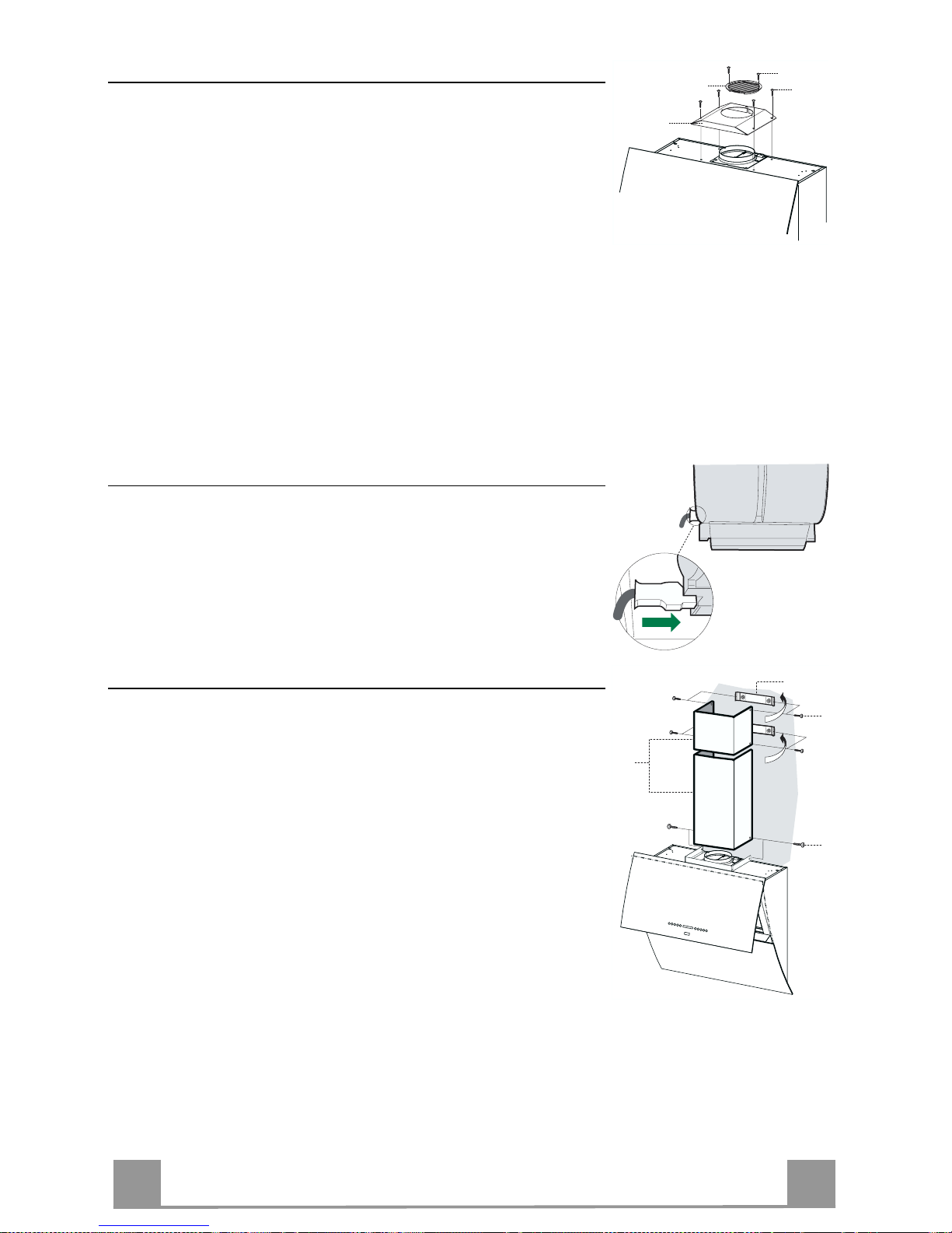
SA
880
ﻊﻳزﻮﺘﻟا ةدﺎﻋا مﺎﻈﻧ
نﻮﺑﺮﻜﻟا ﺮﺗﻼﻓ ﻢﻘﻃ ءاﺮﺷ ﻦﻣ ﺪﺑﻻ ﻊﻳزﻮﺘﻟا ةدﺎﻋا مﺎﻈﻧ ﻲﻓ طﺎﻔﺸﻟا ﺐﻴآﺮﺗ ﺪﻨﻋ .
• ﺔﻨﺧﺪﻤﻟا ﺔﻳواز ﻞﻣﺎﺣ عﺰﻧا
• ﺮﻴﻣﺎﺴﻣ ﺔﻌﺑرا ماﺪﺨﺘﺳﺎﺑ ءاﻮﻬﻟا جﺮﺨﻤﺑ ﺮﺘﻠﻔﻟا ءﺎﻄﻏ ﻂﺑﺮﺑ ﻢﻗ12c ) 2.9 × 12.5
5
(
• ءاﻮﻬﻟا جﺮﺨﻣ ﺔﻜﺒﺷ ﺐﻴآﺮﺘﺑ ﻢﻗ8ﻟا ﻊﻳزﻮﺗ ةدﺎﻋا جﺮﺨﻣ ﻲﻓ ماﺪﺨﺘﺳﺎﺑ ءاﻮﻬ
ﻦﻳرﺎﻤﺴﻣ12d) 2.9 × 9.5 ( طﺎﻔﺸﻟا ﻊﻣ ةدﻮﺟﻮﻤﻟا .
16
12c
12d
8
ءﺎﺑﺮﻬﻜﻟا ﻞﻴﺻﻮﺗ
• ﻲﺑﺮﻬﻜﻟا رﺎﻴﺘﻟا رﺪﺼﺑ طﺎﻔﺸﻟا ﻞﻴﺻﻮﺘﺑ ﻢﻗ
• حﺎﺘﻔﻤﻟا ﻲﻠﻋ ﻂﻐﻀﻟﺎﺑ ﺔﻳﻮﻠﻌﻟا ﺔﺣﻮﻠﻟا ﺢﺘﻔﺑ ﻢﻗA ) ﺔﻘﻳﺮﻄﺑ صﺎﺨﻟا ءﺰﺠﻟا ﻲﻟا ﺮﻈﻧا
ماﺪﺨﺘﺳﻻا ( ﻦﻴﺘﻴﻧﺎﺛ ةﺪﻤﻟ .
• ﺔﻴﻧﺪﻌﻤﻟا ﺮﺗﻼﻔﻟا عﺰﻧا )ﺠﻟا ﺮﻈﻧاﺔﻧﺎﻴﺼﻟا ﺔﻴﻠﻤﻌﺑ صﺎﺨﻟا ءﺰ ( ﻚﻠﺳ ﺔﻠﺻو نا ﺪآﺎﺗو
طﺎﻔﺸﻟا ﺔﺸﻴﻓ ﻞﺧاد ﺢﻴﺤﺻ ﻞﻜﺸﺑ ﺎﻬﺒﻴآﺮﺗ ﻢﺗ ءﺎﺑﺮﻬﻜﻟا.
ﺔﻨﺧﺪﻤﻟا ءاﺰﺟا
يﻮﻠﻌﻟا ءﺰﺠﻟا:-
- ﻒﻠﺧ ﻢﻬﻌﺿو عﺎﻄﺘﺴﻤﻟا رﺪﻘﺑ يﻮﻠﻌﻟا ءﺰﺠﻟا ﻲﺒﻧﺎﺟ ﻊﻴﺳﻮﺘﺑ ﻢﻗ ﻞﻣاﻮﺤﻟا )7/2/1 (
ﺪﻴﺟ ﻞﻜﺸﺑ ﺎﻤهزﺎﻜﺗرا ﻦﻣ ﺪآﺎﺗو .
- ﺪﺨﺘﺳﺎﺑ ﻞﻣاﻮﺤﻟا ﻲﺒﻧﺎﺟ ﺖﻴﺒﺜﺘﺑ ﻢﻗ ما4 ﺮﻴﻣﺎﺴﻣ )12C ) (2.9x9.5 . (
ﻲﻠﻔﺴﻟا ءﺰﺠﻟا:-
- و يﻮﻠﻌﻟا ءﺰﺠﻟا ﻦﻴﺑ ﻢﻬﻌﺿو عﺎﻄﺘﺴﻤﻟا رﺪﻗ ﻲﻠﻔﺴﻟا ءﺰﺠﻟا ﻲﺒﻧﺎﺟ ﺖﻴﺒﺜﺘﺑ ﻢﻗ
ﺪﻴﺟ ﻞﻜﺸﺑ ﺎﻤهزﺎﻜﺗرا ﻦﻣ ﺪآﺎﺗ و ﻂﺋﺎﺤﻟا.
12c
2.1
2.2
2
7.2.1
12c
Page 81

SA
881
ماﺪﺨﺘﺳﻻا
ﻢﻜﺤﺘﻟا ﺔﺣﻮﻟ
ضﺮﻌﻟا ﺔﻔﻴﻇﻮﻟا حﺎﺘﻔﻤﻟا
هرﺎﻴﺘﺧا ﻲﺘﻟا ﺔﻋﺮﺴﻟا ﻲﻟا ﺮﻴﺸﻳ ﺎ ﺔﻘﻠﻐﻣ ﺔﻳﻮﻠﻌﻟا ﺔﺣﻮﻠﻟا ﺖﻧﺎآ اذا : اﺬه ﻲﻠﻋ ﻂﻐﻀﻟا ﺪﻨﻌﻓ
ﺔﻳﻮﻠﻌﻟا ﺔﺣﻮﻠﻟا ﺢﺘﻓ ﻢﺘﻳ ةﺪﺣاو ﺔﻴﻧﺎﺜﻟ حﺎﺘﻔﻤﻟا . ﻞﻴﻐﺸﺗو
ﻞﺒﻗ ﻦﻣ ﺎهرﺎﻴﺘﺧا ﻢﺗ ﻲﺘﻟا ﺔﻋﺮﺴﻟا ﻲﻠﻋ رﻮﺗﻮﻤﻟا
ﺔﺣﻮﺘﻔﻣ ﺔﻳﻮﻠﻌﻟا ﺔﺣﻮﻠﻟا ﺖﻧﺎآ اذا : ﻲﻠﻋ ﻂﻐﻀﻟا ﺪﻨﻌﻓ
رﻮﺗﻮﻤﻟا ﻖﻠﻏو ﺢﺘﻔﺑ مﻮﻘﻳ ﻪﻧﺎﻓ ﺔﻄﻴﺴﺑ ﺔﻄﻐﺿ حﺎﺘﻔﻤﻟا
on/off
A
ﺔﻋﺮﺴﻟا ﺾﻔﺧ ﺮﺷﺆﻣ ﺊﻀﻳ- ﻂﻔﺸﻟا ﺔﻋﺮﺳ ﺾﻔﺨﺑ B
ﺔﻋﺮﺴﻟا ةدﺎﻳز ﺮﺷﺆﻣ ﺊﻀﻳ+ ﻂﻔﺸﻟا ﺔﻋﺮﺳ ﺪﻳﺰﻳ C
ﺮﺷﺆﻤﻟا ﺾﻣﻮﻳI تاﺮﺷﺆﻤﻟا ﻊﻴﻤﺟ ﺊﻀﺗ ﺎﻤﻨﻴﺑ
ﻞﻤﻌﻟا ﻦﻋ ﺔﻴﺻﺎﺨﻟا ﻩﺬه ﻒﻗﻮﺘﺗ حﺎﺘﻔﻤﻟا ﻲﻠﻋ ﻂﻐﻀﻟا ﺪﻨﻋ
.
ﻂﻘﻓ ﺔﺣﻮﻠﻟا ﺢﺘﻓ ﺪﻨﻋ ﻞﻤﻌﻳ . ةﺪﻤﻟ ﻞﻤﻌﺗ ﺔﻋﺮﺴﻟا ﻩﺬﻬﻓ10
ا مﺎﻈﻧ دﻮﻌﻳ ﻚﻟذ ﺪﻌﺑ ﻖﺋﺎﻗد ﻢﺗ ﻲﺘﻟا ﺔﻋﺮﺴﻟا ﻲﻟا ﻞﻴﻐﺸﺘﻟ
ﺎﻴﻜﻴﺗﺎﻣﻮﺗوا ﺎهرﺎﻴﺘﺧا . تﻻﺎﺤﻟ ﺔﺒﺳﺎﻨﻣ ﺔﻔﻴﻇﻮﻟا ﻩﺬهو
ةﺮﻴﺜآ ﺢﺋارو ةﺮﺨﺑا ﺎﻬﻨﻋ ﺔﺠﺗﺎﻨﻟا ﻲﻬﻄﻟا
D
ﺔﻣﻼﻋ ﺊﻀﺗ24 ﺮﺧﻻا ﻮﻠﺗ ﺪﺣاو ﺮﺷﺆﻤﻟا ﻒﻗﻮﺘﻳ ﻢﺛ
ﻞﻤﻌﻟا ﻦﻋ ﺔﻴﺻﺎﺨﻟا ﻩﺬه ﻒﻗﻮﺘﺗ حﺎﺘﻔﻤﻟا ﻲﻠﻋ ﻂﻐﻀﻟا ﺪﻨﻋ
.
ﻂﻘﻓ ﺔﻳﻮﻠﻌﻟا ﺔﺣﻮﻟا ﺢﺘﻓ ﺪﻨﻋ ﻞﻤﻌﻳ . ﻂﻐﻀﻟا ﺪﻨﻋ اﺬه ﻲﻠﻋ
ﻂﻔﺷ ﺔﻋﺮﺳ ﻲﻠﻋ رﻮﺗﻮﻤﻟا ﻂﺒﺿ ﻦﻜﻤﻳ حﺎﺘﻔﻤﻟا100م 3
ﺔﻋﺎﺴﻟا ﻲﻓ
E
ﺰﻣر ﺾﻣﻮﻳ!
ﻦﻋ ﺔﻴﺻﺎﺨﻟا ﻩﺬه ﻒﻗﻮﺘﺗ حﺎﺘﻔﻤﻟا اﺬه ﻲﻠﻋ ﻂﻐﻀﻟا ﺪﻨﻋ
ﻞﻤﻌﻟا .
اﺬه ﻲﻠﻋ ﻂﻐﻀﻟا ﺪﻨﻌﻓ ﻂﻘﻓ رﻮﺗﻮﻤﻟا ﻞﻴﻐﺸﺗ ﺪﻨﻋ ﻞﻤﻌﻳ
و رﻮﺗﻮﻤﻠﻟ ﻞﺟﺆﻤﻟا ﻖﻠﻌﻟا ﺔﻴﺻﺎﺧ ﻂﺒﺿ ﻦﻜﻤﻳ حﺎﺘﻔﻤﻟا
ﺪﻌﺑ ةءﺎﺿﻻا30 ﺔﻘﻴﻗد
F
ﺔﻣﻼﻋ " ﺐﺠﻳ ﻲﻟﺎﺘﻟﺎﺑو نﻮهﺪﻟا ﺮﺗﻼﻓ ﻊﺒﺸﺗ ﻲﻟا ﺮﻴﺸﺗ
ﺮﺗﻼﻔﻟا ﻞﺴﻏ . ﺪﻌﺑ ﺮﺷﺆﻤﻟا ﺊﻀﻳو100 ﻞﻤﻋ ﺔﻋﺎﺳ .
ﺎﻣا
C ﺐﺠﻳ ﻲﻟﺎﺘﻟﺎﺑو نﻮﺑﺮﻜﻟا ﺮﺗﻼﻓ ﻊﺒﺸﺗ ﻲﻟا ﺮﻴﺸﺘﻓ
ﺎﻬﻟاﺪﺒﺘﺳا . ﺪﻌﺑ ﺮﺷﺆﻤﻟا ﺊﻀﻳو200 ﻞﻤﻋ ﺔﻋﺎﺳ
ةدﺎﻋا ﻦﻜﻤﻳ ﻦﻴﺘﻴﻧﺎﺛ ةﺪﻤﻟ حﺎﺘﻔﻤﻟا اﺬه ﻲﻠﻋ ﻂﻐﻀﻟا ﺪﻨﻋ
ﻔﻟا ﻊﺒﺸﺗ ﺔﺟرد سﺎﻴﻗ ﺮﺷﺆﻣ ﻂﺒﺿ ﺮﺗﻼ
G
ةءﺎﺿﻻا ةﻮﻗ ﻦﻣ ﺪﻳﺰﻳ ﻪﻧﺎﻓ حﺎﺘﻔﻤﻟا اﺬه ﻲﻠﻋ ﻂﻐﻀﻟا ﺪﻨﻋ
تﺎﻳﻮﺘﺴﻣ ﺲﻤﺧ ﻲﺘﺣ ﺎﻬﻠﻳﺪﻌﺗ ﻦﻜﻤﻳ ﻲﺘﻟاو
H
ﺔﻘﻠﻐﻣ ﺔﻳﻮﻠﻌﻟا ﺔﺣﻮﻠﻟا ﺖﻧﺎآ اذا : ﻲﻠﻋ ﻂﻌﻀﻟا ﺪﻨﻌﻓ
ﻂﺒﺿو ﺔﻴﻣﺎﻣﻻا ﺔﺣﻮﻠﻟا ﻞﻴﻐﺸﺘﺑ ﻪﻧﺎﻓ ةﺪﺣاو ﺔﻴﻧﺎﺜﻟ حﺎﺘﻔﻤﻟا
ﺔﺟرد ﻲﻠﻋا ﻲﻠﻋ ةءﺎﺿﻻا . ﺔﻳﻮﻠﻌﻟا ﺔﺣﻮﻠﻟا ﺖﻧﺎآ اذا
ﺣﻮﺘﻔﻣ ﺔ : ﻞﻴﻐﺸﺗ ﻢﺘﻳ حﺎﺘﻔﻤﻟا ﻲﻠﻋ ﻂﻐﻀﻟا ﺪﻨﻋ ﻪﻧﺎﻓ
ةءﺎﺿﻻا
on/off
I
ﺔﻘﻠﻐﻣ ﺔﻳﻮﻠﻌﻟا ﺔﺣﻮﻠﻟا اذا : حﺎﺘﻔﻤﻟا ﻲﻠﻋ ﻂﻐﻀﻟا ﺪﻨﻋ ﻪﻧﺎﻓ
رﻮﺗﻮﻨﻟا ﻞﻴﻐﺸﺗ و ﺔﻳﻮﻠﻌﻟا ﺔﺣﻮﻠﻟا ﻞﻴﻐﺸﺗ ﻢﺘﻳ ةﺪﺣاو ﺔﻴﻧﺎﺜﻟ
ﺔﺟرد ﻲﻠﻋا ﻲﻠﻋ ةءﺎﺿﻻا و ﺔﺜﻟﺎﺜﻟا ﺔﻋﺮﺴﻟا ﻲﻠﻋ .
ﺔﺣﻮﺘﻔﻣ ﺔﻳﻮﻠﻌﻟا ﺔﺣﻮﻠﻟا اذا :ﻂﻐﻀﻟا ﺪﻨﻋ ﻪﻧﺎﻓ ﻲﻠﻋ
ﻖﻠﻏو ةءﺎﺿﻻا و رﻮﺗﻮﻤﻟا ﻖﻠﻏ ﻢﺘﻳ ةﺪﺣاو ﺔﻴﻧﺎﺜﻟ حﺎﺘﻔﻤﻟا
ﺔﻳﻮﻠﻌﻟا ﺔﺣﻮﻠﻟا
L
ﺢﻴﺗﺎﻔﻤﻟا ﺔﺣﻮﻟ ﻖﻠﻏ : ﺢﺘﻓ ﻦﻜﻤﻳ نا ﺎﻤآ ةءﺎﺿﻻا و رﻮﺗﻮﻤﻟا ﻖﻠﻏ ﻢﺘﻳ جﺎﺟﺰﻟا ﻒﻴﻈﻨﺗ ﺪﻨﻋ لﺎﺜﻤﻟا ﻞﻴﺒﺳ ﻲﻠﻌﻓ ﺢﻴﺗﺎﻔﻤﻟا ﺔﺣﻮﻟ ﺐﻨﺤﺗ ﻦﻜﻤﻳ
ﺔﻳﻮﻠﻌﻟا ﺔﺣﻮﻠﻟا ﻖﻠﻏو
حﺎﺘﻔﻤﻟا ﻲﻠﻋ ﻂﻐﻀﻟا ﺪﻨﻋ
F ﻲﻧاﻮﺛ ﺲﻤﺧ ةﺪﻤﻟ ﻪﻔﻴﻗﻮﺗ وا ﻪﻠﻴﻐﺸﺗ ﻦﻜﻤﻳ ﺢﻴﺗﺎﻔﻤﻟا ﺔﺣﻮﻟ ﻖﻠﻏ مﺎﻤﺻ ﻪﻧﺎﻓ . ﺪﻨﻋ ﻚﻟذ ﻦﻣ ﺪآﺎﺘﻟا ﻦﻜﻤﻳو
ضﺮﻌﻟا ﻲﻓ تاﺮﺷﺆﻤﻟا ﻦﻣ رﻮﺗﻮﻤﻟا ﻞﻴﻐﺸﺗ
B
A
D
C
E
G
F
I
H
L
Page 82

SA
882
لوﺮﺘﻨآ تﻮﻤﻳﺮﻟا
ﻞﻤﻌﻳ يﺬﻟا و لوﺮﺘﻨآ تﻮﻤﻳﺮﻟا ﺔﻄﺳاﻮﺑ ﺪﻌﺑ ﻦﻋ زﺎﻬﺠﻟا ﻲﻓ ﻢﻜﺤﺘﻟا ﻦﻜﻤﻳ
ﺔﻳرﺎﻄﺑ ﺔﻄﺳاﻮﺑ)1.5 ﺖﻟﻮﻗ ) (LR-AAA . (
- لوﺮﺘﻨآ تﻮﻤﻳر ﻊﺿو مﺪﻋ ﻲﺟﺮﻳ رﺪﺼﻣ يا ﻦﻣ بﺮﻘﻟﺎﺑ
ةراﺮﺤﻠﻟ.
- ﺔﺤﻴﺤﺼﻟا ﺔﻘﻳﺮﻄﻟﺎﺑ ﺔﻜﻠﻬﺘﺴﻤﻟا تﺎﻳرﺎﻄﺒﻟا ﻦﻣ ﺺﻠﺨﺘﻟا ﺐﺠﻳ .
لوﺮﺘﻨآ تﻮﻤﻳﺮﻟا ) ﻢﻜﺤﺘﻟا ﺔﺣﻮﻟ(
T1 ةءﺎﺿﻻا ﺔﻘﻠﻐﻣ ﺔﻳﻮﻠﻌﻟا ﺔﺣﻮﻠﻟا ﺖﻧﺎآ اذا : ﺔﺟرد ﻲﻠﻋ ةءﺎﺿﻻا ﻂﺒﺿاو ﺔﻳ ﻮﻠﻌﻟا ﺔﺣﻮﻠﻟا ﻞﻴﻐﺸﺘﺑ ﻢﻗ
ﺔﺣﻮﺘﻔﻣ ﺔﺣﻮﻠﻟا ﺖﻧﺎآ اذا :ﻐﺸﺘﺑ ﻢﻗ ةءﺎﺿﻻا ﻞﻴon/off
T2 ةءﺎﺿﻻا ﻖﻠﻓا وا ﺔﻄﺳﻮﺘﻤﻟا ﺔﺟرﺪﻟا ﻲﻠﻋ ةءﺎﺿﻻا ﻂﺒﺿا ﺔﺘﻓﺎﺨﻟا ةءﺎﺿﻻا )ﺔﺣﻮﺘﻔﻣ ﺔﻳﻮﻠﻌﻟا ﺔﺣﻮﻠﻟا ﺖﻧﺎآ اذا (
T3رﻮﺗﻮﻤﻟا ﺔﻘﻠﻐﻣ ﺔﻳﻮﻠﻌﻟا ﺔﺣﻮﻠﻟ ا ﺖﻧﺎآ اذا : ﺔﻳﻮﻠﻌﻟا ﺔﺣﻮﻠﻟا ﻞﻴﻐﺸﺘﺑ ﻢﻗ , ﺎهرﺎﻴﺘﺧا ﻢﺗ ﺔﻋﺮﺳ ﺮﺧا ﻲﻠﻋ رﻮﺗﻮﻤﻟا ﻞﻴﻐﺸﺘﺑ ﻢﻗ ﻢﺛ
ﻟا ﺖﻧﺎآ اذا ﺔﺣﻮﺘﻔﻣ ﺔﻳﻮﻠﻌﻟا ﺔﺣﻮﻠ : رﻮﺗﻮﻤﻟا ﻞﻴﻐﺸﺘﺑ ﻢﻗon/off
ﻦﻴﺘﻴﻧﺎﺛ ةﺪﻤﻟ حﺎﺘﻔﻤﻟا ﻲﻠﻋ ﻂﻐﻀﻟا ﺪﻨﻋ :
ﺔﻗﺎﻐﻣ ﺔﻳﻮﻠﻌﻟا ﺔﺣﻮﻠﻟا ﺖﻧﺎآ اذا : ةءﺎﺿﻻا و ﺔﺜﻟﺎﺜﻟا ﺔﻋﺮﺴﻟا ﻲﻠﻋ رﻮﺗﻮﻤﻟا ﻞﻴﻐﺸﺘﺑ ﻢﻗ ﻢﺛ ﺔﻳﻮﻠﻌﻟا ﺔﺣﻮﻠﻟا ﻞﻴﻐﺸﺘﺑ ﻢﻗ
ﺔﺟرد ﻲﻠﻋا ﻲﻠﻋ
ﺔﺣﻮﺘﻔﻣ ﺔﻳﻮﻠﻌﻟا ﺔﺣﻮﻠﻟا اذا : ﻖﻠﻋا ﺔﻳﻮﻠﻌﻟا ﺔﺣﻮﻠﻟا ﻖﻠﻏاو رﻮﺗﻮﻤﻟا و ةءﺎﺿﻻا .
T4 ﺔﻄﻐﺿ ﻞآ ﺪﻨﻋ ﺔﻋﺮﺴﻟا ﺾﻔﺧ
ﻦﻴﺘﻴﻧﺎﺛ ةﺪﻤﻟ ﻂﻐﻀﻟا ﺪﻨﻋ :
ةءﺎﺿﻻا ةﻮﻗ ﺾﻔﺨﻟ
T5 ﺔﻄﻐﺿ ﻞآ ﺪﻨﻋ ﺔﻋﺮﺴﻟا ﺪﻳ ﺰﺗ
ﻦﻴﺘﻴﻧﺎﺛ ةﺪﻤﻟ ﻂﻐﻀﻟا ﺪﻨﻋ :
ةءﺎﺿﻻا ةﻮﻗ ﺪﻳﺰﺗ
T6 ﺔﻔﺜﻜﻤﻟا ﺔﻋﺮﺴﻟا ءﺎﻐﻟا وا ﻞﻴﻌﻔﺘﻟ
T7ﺮﻴﺧﺎﺘﻟا /24 وا ﻞﻴﻌﻔﺘﻟ ﺔﻋﺎﺳ ﻞﻴﺟﺎﺘﻟا ﺔﻴﺻﺎﺧ ءﺎﻐﻟا
ﻦﻴﺘﻴﻧﺎﺛ ةﺪﻤﻟ ﻂﻐﻀﻟا ﺪﻨﻋ:
ﺔﻴﺻﺎﺧ ءﺎﻐﻟا وا ﻞﻴﻌﻔﺘﻟ24 ﺔﻋﺎﺳ
T1
T6
T2
T3
T4
T5
T7
Page 83
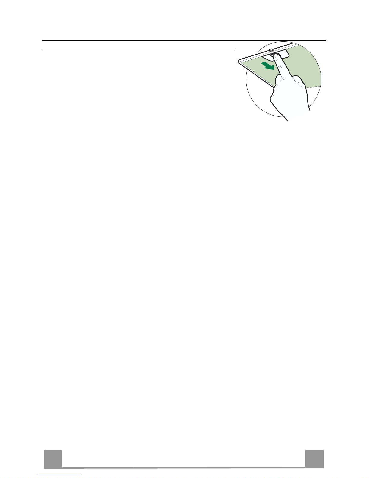
SA
883
ﺔﻧﺎﻴﺼﻟا ﺔﻴﻠﻤﻋ
ﺔﻴﻧﺪﻌﻤﻟا نﻮهﺪﻟا ﺮﺗﻼﻓ
ﺔﻣﻼﻋ رﻮﻬﻇ ﺪﻨﻋ ﺎﻬﻠﺴﻏ ﻢﺘﻳ و قﺎﺒﻃﻻا ﺔﻟﺎﺴﻏ ﻲﻓ ﺮﺗﻼﻔﻟا ﻞﺴﻏ ﻦﻜﻤﻳ" ﻞآ وا ضﺮﻌﻟا ﻲﻓ
ﺔﻟﺎﺣ ﻲﻓ ﺮﺗﻼﻔﻟا ﻞﺴﻏ ﺔﻴﻠﻤﻋ رﺮﻜﺗو ﻦﻳﺮﻬﺷ طﺎﻔﺸﻠﻟ قﺎﺸﻟا ماﺪﺨﺘﺳﻻا .
ﻪﻴﺒﻨﺘﻟا ﺮﺷﺆﻣ ﻂﺒﺿ
• حﺎﺗﺎﻔﻤﻟا ﻂﻐﺿاG ﻞﻗﻻا ﻲﻠﻋ ﻦﻴﺘﻴﻧﺎﺛ ةﺪﻤﻟ
ﺮﺗﻼﻔﻟا ﻒﻴﻈﻨﺗ
• حﺎﺘﻔﻤﻟا ﻲﻠﻋ ﻂﻐﻀﻟﺎﺑ ﺔﻳﻮﻠﻌﻟا ﺔﺣﻮﻠﻟا ﺢﺘﻔﺑ ﻢﻗA ةﺪﺣاو ﺔﻴ ﻧﺎﺜﻟ ) صﺎﺨﻟا ءﺰﺠﻟا ﺮﻈﻧا
ماﺪﺨﺘﺳﻻﺎﺑ (
• ﺖﻗﻮﻟا ﺲﻔﻧ و ﻒﻠﺨﻟا ﻲﻟا ﺎﻤﻬﻌﻓﺪﺑ ﺮﺧﻻا ﻮﻠﺗ ﺪﺣاﻮﻟا ﺮﺗﻼﻔﻟا عﺰﻧا ﻞﻔﺳﻻا ﻲﻟ ا ﻢﻬﺒﺤﺴﺑ ﻢﻗ .
• ﻒ ﻴ ﻈﻨﺘﻟ ا ﺔﻴﻠﻤﻋ ءﺎﻨﺛا ﺮﺗﻼﻔﻠﻟ ﻲﻃ يا ثوﺪﺣ ﺐﻨﺠﺗ ﺐﺠﻳ . ﻞﺧاد ﺮﺗﻼﻔﻟا ﺐﻴ آﺮﺗ ةدﺎﻋا ﻞﺒﻗ
ﺎﻣﺎﻤﺗ ﺔﻓﺎﺟ ﺮﺗﻼﻔﻟا نا ﺪآﺎﺗ طﺎﻔﺸﻟا ) . ﻻ ﻪﻨﻜﻟو ﺖﻗﻮﻟا ﻊﻣ ﺮﺗﻼﻔﻟا ﺢﻄﺳ نﻮﻟ ﺮﻴﻐﺘﻳ ﺎﻤﺑر
ﺮﺗﻼﻔﻟا ةءﺎﻔآ ﻲﻠﻋ ﺮﺛﺆﻳ (
• ﺟﺮﻳ طﺎﻔﺸﻟا ﻞﺧاد ﺮﺗﻼﻔﻟا ﺐﻴ آﺮﺗ ةدﺎﻋا ﺪﻨﻋ ﺢﻴﺤﺻ ﻞﻜﺸﺑ ﻢﻬﺒﻴآﺮﺗ ﻢﺗ ﻪﻧ ا ﻦﻣ ﻩﺎﺒﺘﻧﻻا ﻲ.
Page 84

SA
884
نﻮﺑﺮﻜﻟا ﺮﺘﻠﻓ )ﻊﻳزﻮﺘﻟا ةدﺎﻋا مﺎﻈﻧ(
ﻩﺪﻳﺪﺠﺗ وا ﻪﻠﺴﻏ ﻦﻜﻤﻳﻻ ﺮﺘﻠﻔﻟا اﺬه . ﺮﺷﺆﻤﻟا ﺊﻀﻳ ﺎﻣﺪﻨﻋ ﻪﻟاﺪﺒﺘﺳا ﻦﻣ ﺪﺑﻻ ﻞﺑC ﻞآ وا 4 ﻞﻗﻻا ﻲﻠﻋ رﻮﻬﺷ . ﺔﻴﺻﺎﺧ ﻞﻴﻌﻔﺗ ﺐﺠﻳ
ﻞﺒﻗ ﻦﻣ ﺮﺗﻼﻔﻟا ﻊﺒﺸﺗ ﺔﺟرﺪﺑ ﺔﺻﺎﺨﻟا ﻪﻴﺒﺘﻟا
ا تارﺎﺷا ﻞﻴﻌﻔﺗ ﻪﻴﺒﻨﺘﻟ
• وا ﺐﻴ آﺮﺘﻟا ءﺎﻨﺛا ﻚﻟذو ﺮﺗ ﻼﻔﻟا ﻊﺒ ﺸﺗ ﺔﺟرد سﺎﻴﻘﺑ ﺔﺻﺎﺨﻟا ﻪﻴﺒﺘﻟا ﺔﻴﺻﺎﺧ ﻞﻴﻌﻔﺗ ﻦﻣ ﺪﺑﻻ ﻊﻳزﻮﺘﻟا ةدﺎﻋا ﻊﺿو ﻲﻓ طﺎﻔﺸﻟا ﻂﺒﺿ ﺪﻨﻋ
ﺪﻌﺑ ﺎﻤﻴﻓ
• ةءﺎﺿﻻا و طﺎﻔﺸﻟا ﻖﻠﻏا
• حﺎﺘﻔﻤﻟا ﻂﻐﺿاE ةﺪﻤﻟ 5 ضﺮﻌﻟا ﻲﻓ رﻮﺗﻮﻤﻟا تاﺮﺷﺆﻣ ﻦﻣ ﻦﻳﺮﺷﺆﻣ ﺮﺧا ﺊﻀﺗ ﻲﺘﺣ ﻲﻧاﻮﺛ
• حﺎﺘﻔﻤﻟا كﺮﺗ ﺪﻌﺑE ﺾﻴﻣﻮﻟا ﻲﻓ ﺔﻋﺎﺴﻟا ﺔﻧﻮﻘﻳا اﺪﺒﺗ
• حﺎﺘﻔﻤﻟا ﻂﻐﺿاD ةﺪﻤﻟ 3 ﺮﺗﻼﻔﻟا ﻊﺒﺸﺗ ﻪﻴﺒﻨﺗ تارﺎﺷا فﺎﻘ ﻳ ا وا ﻞﻴﻌﻔﺘﻟ ﻲﻧاﻮﺛ
• ﺔﻣﻼﻌﻟا ﺊﻀﺗ ﺎﻣﺪﻨﻋC ﺮﺗﻼﻔﻟا ﻊﺒﺸﺗ ﻪﻴﺒﺘﻟا تارﺎﺷا ﻞﻴ ﻌﻔﺗ ﻲﻟا ﺮﻴﺸﻳ
• ﺔﻣﻼﻌﻟا ةءﺎﺿا مﺪﻋCﺔﻠﻌﻔﻣ ﺮﻴﻏ ﺮﺗﻼﻔﻟا ﻊﺸﺒﺗ ﻪﻴﺒ ﻨﺘﻟا تارﺎﺷا نا ﻲﻟا ﺮﻴﺸﻳ
نﻮﺑﺮﻜﻟا ﺮﺗﻼﻓ لاﺪﺒﺘﺳا
ﻪﻴﺒﺘﻟا ﺮﺷ ﺆﻣ ﻂﺒﺻ
• حﺎﺘﻔﻤﻟا ﻲﻠﻋ ﻂﻐﺿاG ﻞﻗﻻا ﻲﻠﻋ ﻦﻴﺘﻴﻧﺎ ﺛ ةﺪﻤﻟ
ﺮﺘﻠﻔﻟا لاﺪﺒﺘﺳا
• حﺎﺘﻔﻤﻟا ﻲﻠﻋ ﻂﻐﻀﻟﺎﺑ ﺔﻳﻮﻠﻌﻟا ﺔﺣﻮﻠﻟا ﺢﺘﻔﺑ ﻢﻗA ﺔﻴﻧﺎﺜﻟ ) ماﺪﺨﺘﺳﻻﺎﺑ صﺎﺨﻟا ءﺰﺠﻟا ﺮﻈﻧا
(
• ﺔﻴﻧﺪﻌﻤﻟا ﺮﺗﻼﻔﻟا عﺰﻧ ا
• ﻲﻓ رﺎﺸﻣ ﻮه ﺎﻤآ ﺔﻌﺒﺸﻤﻟا نﻮﺑﺮﻜﻟا ﺮﺗﻼﻓ عﺰﻧ ا ةﺮﻘﻔﻟاA
• ةﺮﻘﻔﻟا ﻲﻓ رﺎﺸﻣ ﻮه ﺎﻤآ ةﺪﻳﺪﺠﻟا ﺮﺗﻼﻔﻟا ﺐﻴآﺮﺗ ﺪﻋاB
• ﺎﻬﻧﺎﻜﻣ ﻲﻓ ﺔﻴﻧﺪﻌﻤﻟا نﻮهﺪﻟا ﺮﺗﻼﻓ ﻊﺿ
A
B
ةءﺎﺿﻻا
ةءﺎﺿﻻا لاﺪﺒﺘﺳا
ﻦﻴﺟﻮﻠﻴه ﺔﺒﻤﻟ20 تاو
• ﻖﻓﺮﺑ ﺔﺒﻤﻠﻟا ﻚﺳﺎﻣ ﺐﺤﺴﺑ ﺎﻬﻧﺎﻜﻣ ﻦﻣ ﺔﺒﻤﻠﻟا عﺰﻧا
• ﺟ ﻞﻜﺸﺑ ﺎﻬﻄﺑر ﻦﻣ ﺪآﺎﺗو عﻮﻨﻟا ﺲﻔﻧ ﻦﻣ يﺮﺧا ﺔﺒﻤﻟ ﺐﻴآﺮﺗ ﺪﻋا ﻲﻓ ﺪﻴ
ﺎﻬﻧﺎﻜﻣ
Page 85

SA
885
ﺮﻬﺼﻤﻟا لاﺪﺒﺘﺳا
ﺔﻄﺳاﻮﺑ ﻞﻤﻌﻳ يﺬﻟا رﻮﺗﻮﻤﻟا ﻞﻐﺸﻣ لﻼﺧ ﻦﻣ ﻢﺘﺗ طﺎﻔﺸﻟا ﺢﺘﻓو ﻖﻠﻏ مﺎﻈﻧ
ﺮﻬﺼﻣ . ﻂﻘﻓ رﻮﺗﻮﻤﻟا ﻞﻴﻐﺸﺗ ﺪﻨﻋ ﻞﻤﻌﻳ ﻮهو . ﺮﻬﺼﻤﻟا اﺬه ضﺮﻌﺗ اذاو
عﺎﺒﺗاو ﺎﻳوﺪﻳ طﺎﻔﺸﻟا ﺢﺘﻓ ﻦﻣ ﺪﺑﻻ ﺔﻟﺎﺤﻟا ﻩﺬه ﻲﻓو ﺔﺣﻮﻠﻟا ﻖﻠﻏ ﺪﻨﻋ ﻒﻠﺘﻠﻟ
ﺔﻴﻟﺎﺘﻟا تاﻮﻄﺨﻟا :
• ا عﺰﻧا ﺮﺴﻳﻻا ﺐﻧﺎﺠﻟا ﻲﻠﻋ دﻮﺟﻮﻤﻟا ءﺎﻄﻐﻟ
• ﺢﺘﻓ ﻚﻟ ﺢﻴﺘﻳ يﺬﻟا مزﻼﻟﻻا رﺪﻘﻟﺎ ﺑ ﻚﻔﻤﻟﺎﺑ ﺔﻌﻓاﺮﻟا ﺾﺒﻘﻣ ﻲﻠﻋ ﻂﻐﺿا
طﺎﻔﺸﻟا
• عﺎﺒﺗا لﻼﺧ ﻦﻣ ﺔﻴﻧﺪﻌﻤﻟا نﻮهﺪﻟا ﺮﺗﻼﻓ عﺰﻧا ﺔﺣﻮﻠﻟا ﺢﺘﻓ ﻢﺘﻳ نا ﺪﻌﺑ
ﺮﺗﻼﻔﻟا ﻒﻴﻈﻨﺗ ﺔﻴﻠﻤﻌﺑ صﺎﺨﻟا ءﺰﺠﻟا ﻲﻓ ﺎﻬﻟ ةرﺎﺷﻻا ﻖﺒﺳ ﻲﺘﻟا تﺎﻤﻴﻠﻌﺘﻟا .
• ﻠﻋ ﺮﻬﺼﻤﻟا ﺪﺟﻮﻳ ﻦﻤﻳﻻا ﺐﻧﺎﺠﻟا ﻲ . ﻮه ﺎﻤآ ﺮﻬﺼﻤﻟا ﻞﻣﺎﺣ ﻚﻔﺑ ﺎﻤآ
رﺎﺸﻣ . تﺎﻔﺻاﻮﻤﻟا ﺲﻔﻨﺑ ﺪﻳﺪﺟ ﺮﺧﺎﺑ ﻪﻟاﺪﺒ ﺘﺳاو .
• يﺮﺧا ةﺮﻣ ﺎﻬﻨآﺎﻣا ﻲﻓ نﻮهﺪﻟا ﺮﺗﻼﻓ و ﺮﻬﺼﻤﻟا ﻞﻣﺎﺣ ﻊﺿ . نا ﺪآ ﺎ ﺗ و
ﺪﻴﺟ ﻞﻜﺸﺑ ﻞﻤﻌﻳ طﺎﻔﺸﻟا . ﻦﻣ ﺪﺑﻼﻓ ﺪﻴﺟ ﻞﻜﺸﺑ ﻞﻤﻌﻳ ﻻ طﺎﻔﺸﻟا نﺎآ اذا
ﺪﻤﺘﻌﻤﻟا ﺔﻧﺎﻴﺼﻟا لﻮﺌﺴﻤﺑ لﺎﺼﺗﻻا.
ﺣ ﻲﻓ و نﻮهﺪﻟا ﺮﺗﻼﻓ عﺰﻧ ﻲﻔﻜﻴﻓ طﺎﻔﺸﻟا ﻞﻴﻐﺸﺗ ﺔﻳاﺪﺑ ﻲﻓ ﺮﻬﺼﻤﻟا ﻒﻠﺗ ﺔﻟﺎ
ﺮﻬﺼﻤﻟا لاﺪﺒﺘﺳا .
Page 86

Page 87

Page 88

436003307_ver6
The symbol on the product or on it s pac kaging indi cates that this pr o d uc t m ay n ot b e tr e ated as house hol d w as te. Instead it shall
be handed ov er to the applicable c ollectio n point for the recyc ling of elec trical and electroni c equipm ent. By ensur ing this product is
disposed of correctly, you will help prevent potential negative consequences for the environment and human health, which could otherwise be caus ed by in appr opr iat e wast e han dli ng of this produc t. F or mor e detai led infor mati o n about recyc li ng of this produc t , ple ase
contact your local city office, your household waste disposal service or the shop where you purchased the product.
Le symbole s ur le pr odui t ou so n em ball age i ndi que q ue c e prod uit ne pe ut êtr e trai té com m e déc het m éna ger. Il d oit plut ôt êtr e
remis au point de ramassage concerné, se chargeant du recyclage du matériel électrique et électronique. En vous assurant que ce
produit est él imi né correc temen t, vous favori sez l a préve ntion des conséq uenc es nég atives p our l’ envir onnem ent et la sa nté hum aine
qui, sinon, s er ai e nt l e r ésultat d’u n trai tement inap pr o pr i é d es d éc h ets d e c e produit. Pour o bt enir plus de détails sur l e rec yclage de ce
produit, veuillez prendre contact avec le bureau municipal de votre région, votre service d’élimination des déchets ménagers ou le
magasin où vo us av ez acheté le produi t.
Das Symbol auf dem Pro dukt o der sei ner Ver packu ng weis t dar auf hin, dass di eses Pr oduk t nicht al s norm aler H aushal tsabfal l
zu behand eln ist, s on der n an ein em S am mel pu nkt f ür das Recy cl ing v on elek tri sche n und elek troni sc he n Ger äte n ab geg ebe n w erde n
muss. Durc h Ihren Beitra g zum korr ekten Entsorgen dieses Produkts schützen Si e die Umwelt un d die Gesund h ei t I hr er M i tm e ns chen.
Umwelt und Gesundheit werden durch falsches Entsorgen gefährdet. Weitere Informationen über das Recycling dieses Produkts
erhalten Sie von Ihrem Rathaus, Ihrer Müllabfuhr oder dem Geschäft, in dem Sie das Produkt gekauft haben.
El símbol o en el pr o ducto o en su embalaj e indica q ue es te produc t o n o se puede tr a t ar como desperdici os nor males del ho gar.
Este produc to s e de be e ntre gar al p unto de r ec olecc ió n de e qui pos eléc tri cos y el ectró nic os p ar a reci cl aje. Al as egur ars e de q u e est e
producto se desec he corr ect ament e, uste d ayu dará a ev itar p osibles cons ecuenc ias negati vas par a el am bien te y la sal ud pú blic a, lo
cual podrí a ocurr ir si este produc to no s e mani pula de f orma a decuad a. Par a obtener inform aci ón más de talla da sobr e el reci claj e de
este produc t o, pó ngas e e n cont ac to c on l a a dm ini strac ión de s u ci ud ad, co n su ser vic io d e des ec hos d el hog ar o c on l a ti end a do nde
compró el producto.
Το σύµβολο στο προϊόν ή επάνω στη συσκευασία του υποδεικνύει ότι δεν πρέπει να µ εταχειρίζεστε το προϊόν αυτό ως οικιακό
απόρριµµα . Αντιθέτως θα πρέπει να παραδίδεται στο κατάλληλο σηµείο συλλογής για την ανακύκλωση ηλεκτρικού και ηλεκτρονικού εξοπλισµού. Εξασφαλίζοντας ότι το προϊόν αυτό διατίθεται σωστά, συµβάλλετε στην αποτροπή ενδεχόµενων αρνητικών συνεπειών για το περιβάλλον και την ανθρώπινη υγεία, οι οποίες θα µ πορούσαν διαφορετικά να προκληθούν από ακατάλληλο χειρισµό
απόρριψης του προϊόντος αυτού. Για λεπτοµερέστερες πληροφορίες σχετικά µ ε την ανακύκλωση του προϊόντος αυτού, επικοινωνήστε µε το δηµαρχείο της περιοχής σας, την τοπική σας υπηρεσία αποκοµιδής οικιακών απορριµµάτων ή µε το κατάστηµα όπου
αγοράσατε το προϊόν.
Символ на изделии или на его упаковке указывает, что оно не подлежит утилизации в качестве бытовых отходов.
Вместо этого его следует сдать в соответствующий пункт приемки электронного и электрооборудования для последующей
утилизации. Соблюдая правила утилизации изделия, Вы поможете предотвратить причинение окружающей среде и здоровью
людей потенциального ущерба, кот орый возможен, в противном случае, вследствие неподобающего обращения с подобными
отходами. За более подробной информацией об утилизации этого изделия просьба обращаться к местным властям, в службу
по вывозу и утилизации отходов или в магазин, в котором Вы приобрели изделие.
 Loading...