

Page 1
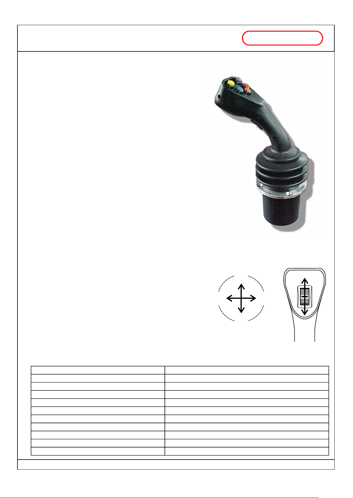
2 / 3 axis joystick
JP
DESCRIPTION
JP is a 2 or 3 axis electronic joystick with power outputs, able to
directly control up to 6 proportional solenoid valves with PWM
outputs proportional to joystick movements.
Joystick movements are derived from the measurement of the
magnetic field produced by permanent ferromagnets; the
measurement is taken through redundant Hall effect probes. This
kind of probes are not subject to usury.
JP contains a microprocessor electronic card; this makes the
joystick very reliable and highly customizable.
Also the push button panel is customizable.
Main characteristics:
- you can control two or three proportional indipendent axis (4 or
6 PWM outputs) or just one proportional output (PWM) with 4 or
6 ON/OFF outputs
- optional "virtual cross" to forbid diagonal movements
- linear or parabolic output curve
- up to 3 speed set selectionable by two input
- straight BYPASS output, with delayed turn off
- FAULT output
- standard or capacitive dead man switch
- indipendent regulation (for each semiaxis) of
l minimum current
l maximum current
l rise timeramp
l fall timeramp
- PWM frequency adjustable from 50 to 300 Hz
- power supply voltage from 10Vdc to 30Vdc
- completely resinated electronic card
- third proportional axis THUMBWHEEL ready to mount
- provided with a 50 cm long unpluggable cable
with power outputs (PWM)
FABER -
two principal axis
YA
YB
COM
third axis
THUMBWHEEL
(optional)
ZA
XAXB
ZB
Joystick
movements
TECHNICAL SPECIFICATIONS
Power Supply Voltage
Current absorption
Working temperature range
PWM output minimum current
PWM output maximum current
Available PWM frequency
ON/OFF output maximum current
Maximum number of manoeuvres
Connections
Under panel size
Programming Device
FABER-COM srl - Via Romana 36/1 - 42028 Poviglio (RE) - Italy Tel. +39-0522-960428 Fax. +39-0522-969644 - www.fabercom.itFABER-COM srl - Via Romana 36/1 - 42028 Poviglio (RE) - Italy Tel. +39-0522-960428 Fax. +39-0522-969644 - www.fabercom.it
FABER-COM srl - Via Romana 36/1 - 42028 Poviglio (RE) - Italy Tel. +39-0522-960428 Fax. +39-0522-969644 - www.fabercom.it
Tecnico\Prodotti\Manipolatore\Jp\Documenti\SM#Manuale JP_v102_ie.cdr - 11/01/07
10Vdc ÷ 30Vdc
200 mA + output load (max 10A)
-20 ÷ 70 °C
from 100 to 2500 mA (with 10 mA resolution)
from 100 to 2500 mA (with 10 mA resolution)
50-60-70-85-100-125-150-200-250-300 Hz
2500 mA
3 PWM outputs at the same time
14 poles Molex minifit Jr. conn. with a 50 cm cable included
diameter 80 - width 90 mm
PRG2 serial keyboard
Page 1 / 8
Page 2
2 / 3 axis joystick
JP
WORKING MODE
The FAULT output in normal operating conditions supplies a positive output (max 2,5A).
In faulty conditions the FAULT output is turned off.
Connecting this signal to a system that puts the installation in safety conditions it is possible to stop the machine
operations in case of joystick fault.
The BYPASS output is turned on (positive output max 2,5 mA) every time the joystick is moved from the zero position.
When the joystick is released the output is turned off with a 0,4 seconds delay (programmable).
SIGNALS
The red and the green LEDs under the joystick are used to show different working conditions.
In normal operating conditions, the red LED is used as a power supply LED; it is turned on when the power
supply is present.
Red LED is turned off for a little while when bypass output is turned on or off.
with power outputs (PWM)
FABER -
COM
In case of faulty operations the two LEDs flash in various modes depending on the fault type:
RED LED
Two flash: system turned on with the joystick not at zero position. Outputs will stay turned off. It is necessary
to turn off the joystick and turn it on again releasing the lever.
Four flash: Internal error on the magnetic sensors (excessive signal difference between the two probes of
the same channel) or movement of the lever too fast. It remains blocked until it is turned off.
Five flash: Internal error on the magnetic sensors or on the third axis input (signal out of range). It remains
blocked until it is turned off.
Seven flash: Calibrating parameters not valid. It remains blocked until it is turned off.
GREEN LED
When you move the joystick, the green led is turned on proportional to the greater current supplied. If joystick
is not plugged or a wired is broken, the green LED will stay turned off because no current will be supplied.
RED and GREEN LED at the same time
One flash at second: joystick has to be calibrated. Follow the appropriate procedure (reserved).
VIRTUAL CROSS
PWM outputs are turned on to regulate the current that flows in the load proportional to the movements of the
joystick. If you activate the "virtual cross" function, you will be able to move joystick in just one direction at a time:
the first manoeuvre done forbids all the other manoeuvres until the joystick will return at rest position.
Otherwise, if the "virtual cross" function is not activated, you will be able to do two manovreus at the same time,
by moving the joystick in diagonal direction.
The "virtual cross" fuction, if activated, is referred only to the two principal axis; the third axis, if present, will
continue to work indipendently to the two other axis.
FABER-COM srl - Via Romana 36/1 - 42028 Poviglio (RE) - Italy Tel. +39-0522-960428 Fax. +39-0522-969644 - www.fabercom.itFABER-COM srl - Via Romana 36/1 - 42028 Poviglio (RE) - Italy Tel. +39-0522-960428 Fax. +39-0522-969644 - www.fabercom.it
FABER-COM srl - Via Romana 36/1 - 42028 Poviglio (RE) - Italy Tel. +39-0522-960428 Fax. +39-0522-969644 - www.fabercom.it
Tecnico\Prodotti\Manipolatore\Jp\Documenti\SM#Manuale JP_v102_ie.cdr - 11/01/07
Page 2 / 8
Page 3
2 / 3 axis joystick
JP
PROGRAMMING MODE
To adjust JP working parameters, it is necessary to plug the PRG2 programming keyboard into the appropriate
connector. JP automatically recognise PRG2 connected and modify his working way to allow current calibration as
described below
Adjustable parameters:
The number of flashes of the programming keyboard LED indicates the programming step in which you are.
As PRG2 is connected You are in step no. 1.
By the pressure of "PREV" and "NEXT" push buttons you are able to navigate through the programming steps;
otherwise, by the pressure of "+" "-" push buttons you are able to increase and decrease the parameter
corresponding to the actual programming step.
At the end of the programming procedure, you have to push "PREV" and "NEXT" push buttons at the same time
to save in memory the new parameters value. If You do not give the SAVE command all modification will be loose
when JP is turned off.
Step 1: minimum current regulation (manoeuvres start up speed)
Step 2: maximum current regulation (manoeuvres max speed)
Step 3: rise timeramp regulation (manoeuvres acceleration speed)
Step 4: fall timeramp regulation (manoeuvres deceleration speed)
Step 5: bypass delay regulation (bypass delay time when all the manoeuvres stop)
Step 6: PWM frequency regulation (to reduce the solenoid valves histeresis)
with power outputs (PWM)
.
FABER -
COM
For the programming steps from 1 to 4 it is necessary move the joystick to choose the manoeuvre which has to
be regulated. Actually, it is possible to set different values of min/max currents, rise/fall timeramp for each
movement (semi-axis).
During the programming mode, joystick continues to work normally to give you a real time feedback of the
changes done.
The only programming step which modifies joystick behaviour is step number 1, in which you regulate the
manoeuvres start up speeds. When the joystick is into this programming step, when you move the joystick the
manoeuvres will be turned on only at their start up speed; You have to adjust start speed until all manoeuvres will
start to move very slowly or are near to start.
When You move into programming step number 2, to tune maximum speed, You can verify the complete range of
the output currents from the minimum speed (regulated in the programming step number 2) to the maximum
speed (regulated here).
While the programming steps for 1 to 5 give you a real time feedback of the modifications, the programming step
number 6 (PWM frequency regulation) does not. If you cannot estimate the effects of the modifications, you have
to do a "blind" regulation.
So you have to know the right frequency value for the solenoid valve that you are using (usually indicated by
manufacturer). Find in the following table the index that correspond to the requested frequency.
When you are in programming step number 6, press for at least 2 seconds the "'-" button (in this way you reach
the 0 value of the frequency parameter). Then push the "+" button a number of times equal to the desired
frequency corresponding number.
NOTE: Remember to save parameters before turning off the joystick.
Table of available frequences for PWM
PWM freq.
Index
FABER-COM srl - Via Romana 36/1 - 42028 Poviglio (RE) - Italy Tel. +39-0522-960428 Fax. +39-0522-969644 - www.fabercom.itFABER-COM srl - Via Romana 36/1 - 42028 Poviglio (RE) - Italy Tel. +39-0522-960428 Fax. +39-0522-969644 - www.fabercom.it
FABER-COM srl - Via Romana 36/1 - 42028 Poviglio (RE) - Italy Tel. +39-0522-960428 Fax. +39-0522-969644 - www.fabercom.it
Tecnico\Prodotti\Manipolatore\Jp\Documenti\SM#Manuale JP_v102_ie.cdr - 11/01/07
50 Hz 60 Hz 70 Hz 85 Hz 100 Hz 125 Hz 150 Hz 200 Hz 250 Hz 300 Hz
0 1 2 3 4 5 6 7 8 9
Page 3 / 8
Page 4
JP
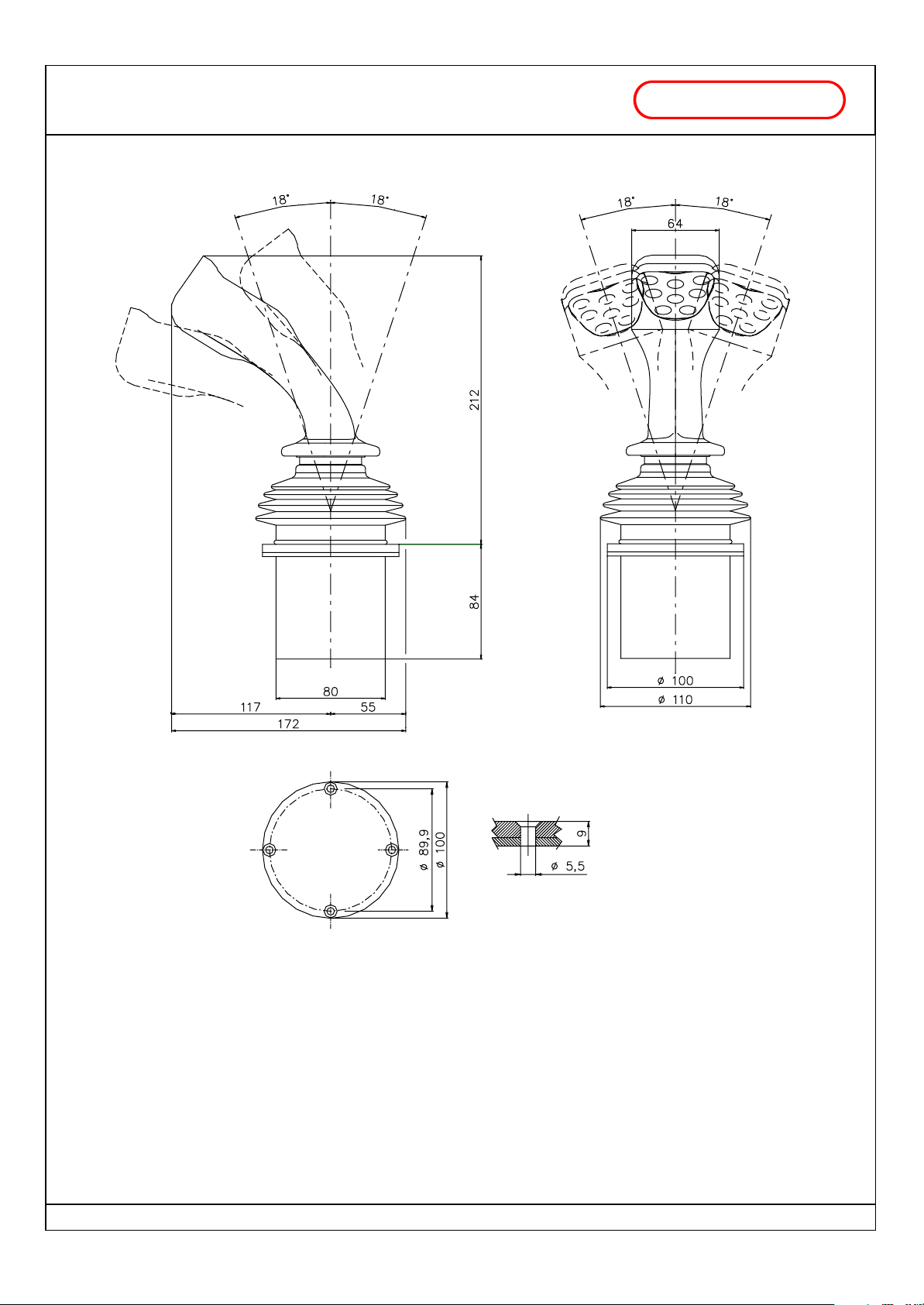
SIZE
2 / 3 axis joystick
with power outputs (PWM)
FABER -
COM
FABER-COM srl - Via Romana 36/1 - 42028 Poviglio (RE) - Italy Tel. +39-0522-960428 Fax. +39-0522-969644 - www.fabercom.itFABER-COM srl - Via Romana 36/1 - 42028 Poviglio (RE) - Italy Tel. +39-0522-960428 Fax. +39-0522-969644 - www.fabercom.it
FABER-COM srl - Via Romana 36/1 - 42028 Poviglio (RE) - Italy Tel. +39-0522-960428 Fax. +39-0522-969644 - www.fabercom.it
Tecnico\Prodotti\Manipolatore\Jp\Documenti\SM#Manuale JP_v102_ie.cdr - 11/01/07
Page 4 / 8
Page 5
JP
2 / 3 axis joystick
with power outputs (PWM)
FABER -
COM
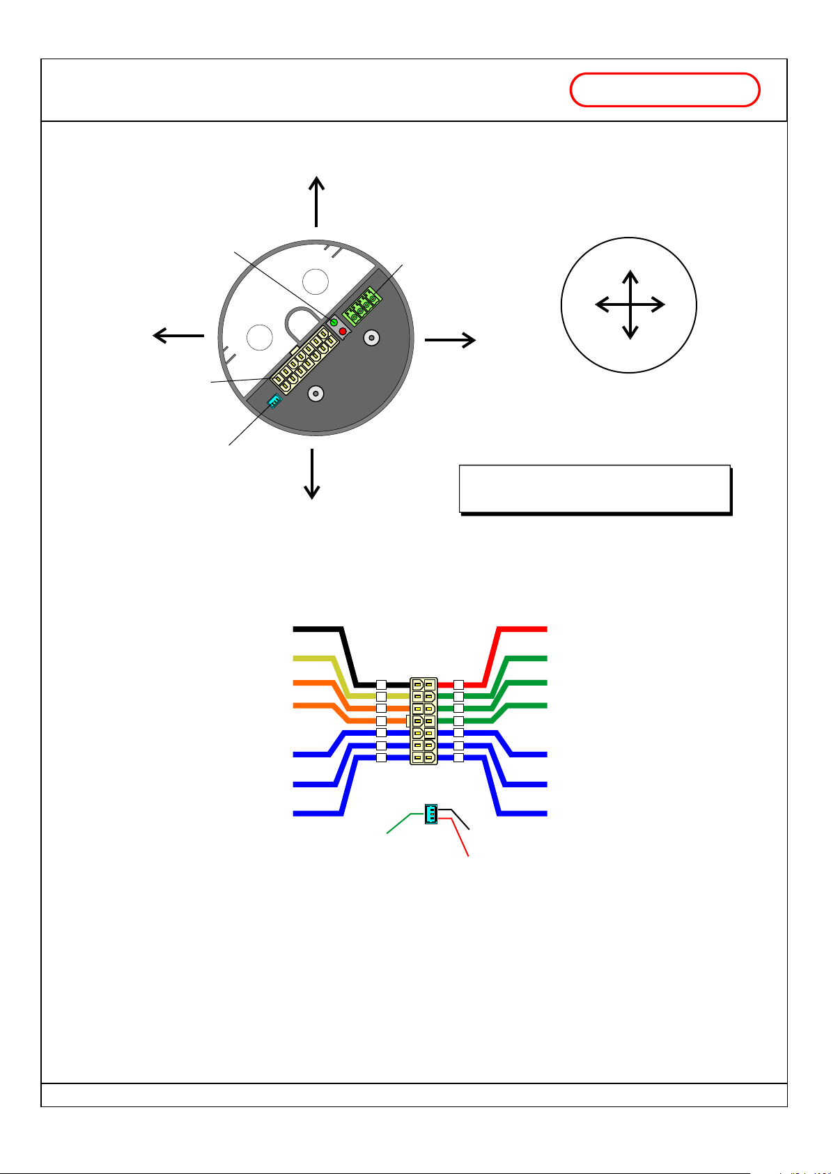
Bottom view
YB
AXIS
Serial Port
2 diagnostic
LED
for PRG2 programming
keyboard
XB
AXIS
14 poles
connector for supply voltage
MOLEX Minifit jr.
inputs and outputs
Thumbwheel
connector
(Z axis)
YA
AXIS
Joystick will be provided with a 50 cm unpluggable cable
Upper view
YA
XA
AXIS
YB
IN1 = Set2 selection input (Fast/ Slow)
IO2 = OUT (Fault / Aux / Prop. section) - IN (Set3 selection)
IO3 = OUT (Bypass) - IN (Set3 selection)
NOTE: In each specific version of JP joystick signals
IN1, IO2 and IO3 can have different meanings.
Please refer to the sheet of the specific JP versions.
XAXB
Negativo
alimentazione
IN1 (input)
IO2 (input/output)
IO3 (input/output)
XB axis PWM positive pole
YB axis PWM positive pole
ZB axis PWM positive pole
BLAK
YELLOW
ORANGE
ORANGE
BLUE
BLUE
BLUE
Thumbwheel
signal
0.5V - 4.5V
RED
Positive supply
voltage
GREEN
X axis negative pole
8
9
10
11
12
13
14
1
1
2
3
4
5
6
7
Negative
Positive
GREEN
Y axis negative pole
GREEN
Z axis negative pole
BLUE
XA axis PWM positive pole
BLUE
YA axis PWM positive pole
BLUE
ZA axis PWM positive pole
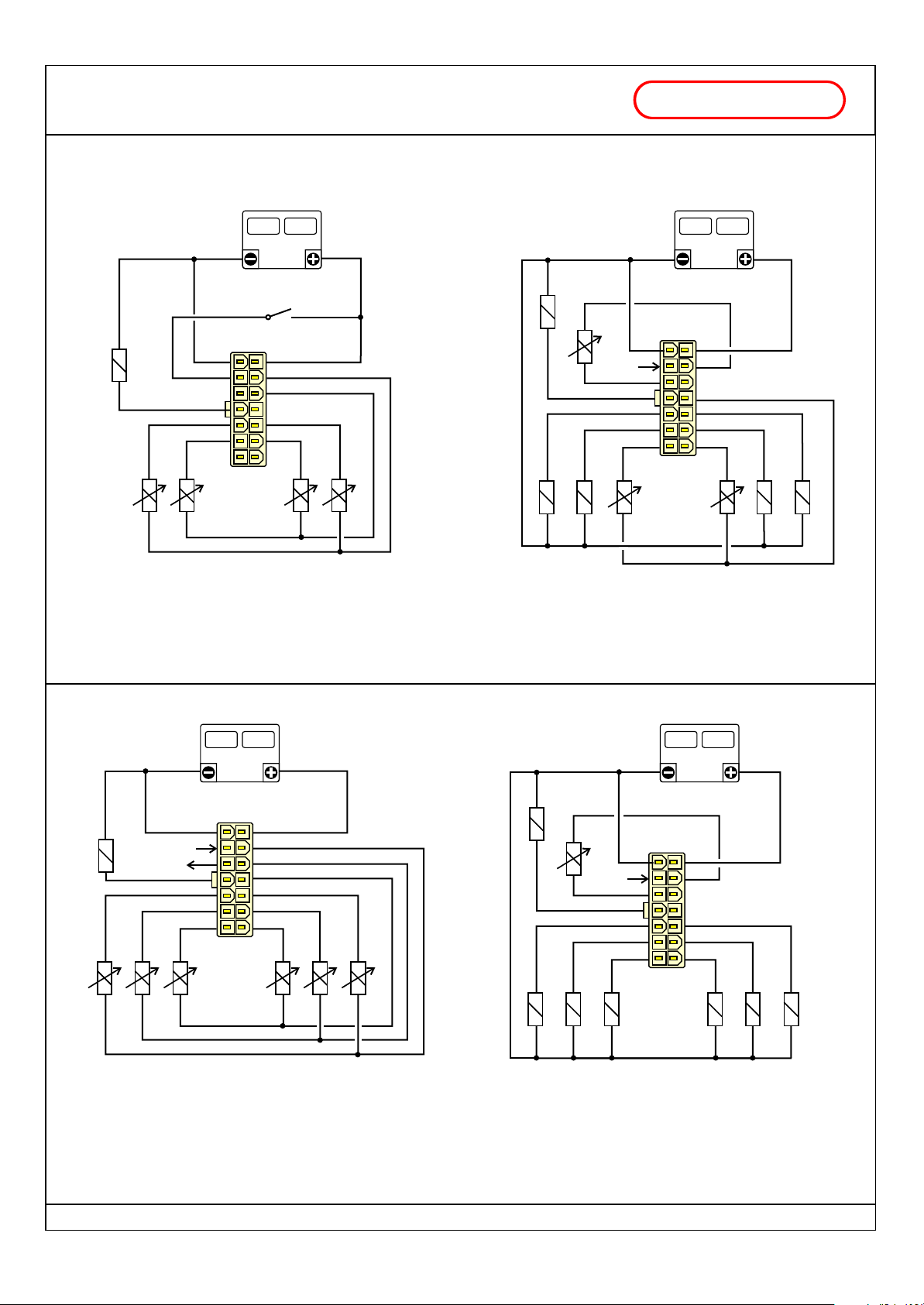
Connection examples in the following page show some possible configurations that can be realized with JP.
Each example can require a specific configuration of JP joystick.
FABER-COM srl - Via Romana 36/1 - 42028 Poviglio (RE) - Italy Tel. +39-0522-960428 Fax. +39-0522-969644 - www.fabercom.itFABER-COM srl - Via Romana 36/1 - 42028 Poviglio (RE) - Italy Tel. +39-0522-960428 Fax. +39-0522-969644 - www.fabercom.it
FABER-COM srl - Via Romana 36/1 - 42028 Poviglio (RE) - Italy Tel. +39-0522-960428 Fax. +39-0522-969644 - www.fabercom.it
Tecnico\Prodotti\Manipolatore\Jp\Documenti\SM#Manuale JP_v102_ie.cdr - 11/01/07
Page 5 / 8
Page 6
2 / 3 axis joystick
JP
CONFIGURATION EXAMPLES
with power outputs (PWM)
FABER -
COM
BATTERY
12V / 24V
Bypass
Fast/Slow
1
Ya XaXb Yb
- 2 proportional indipendent PWM sections (A+B)
- bypass output
- speed selection input (Fast/Slow)
BATTERY
12V / 24V
Bypass
PWM
unico
1
Fast/Slow
Za Ya XaXb Yb Zb
- 1 proportional PWM output + 4 ON/OFF directional outputs
- 1 proportional PWM section (A+B)
- bypass output
- speed selection input (Fast/Slow)
BATTERY
12V / 24V
1
Fast/Slow
Fault
Bypass
Za Ya XaXb Yb Zb
- 3 proportional PWM sections
- bypass output
- fault output
- speed selection input (Fast/Slow)
BATTERY
12V / 24V
Bypass
PWM
unico
1
Fast/Slow
Za Ya XaXb Yb Zb
- 1 proportional PWM output + 6 ON/OFF directional outputs
- bypass output
- speed selection input (Fast/Slow)
FABER-COM srl - Via Romana 36/1 - 42028 Poviglio (RE) - Italy Tel. +39-0522-960428 Fax. +39-0522-969644 - www.fabercom.itFABER-COM srl - Via Romana 36/1 - 42028 Poviglio (RE) - Italy Tel. +39-0522-960428 Fax. +39-0522-969644 - www.fabercom.it
FABER-COM srl - Via Romana 36/1 - 42028 Poviglio (RE) - Italy Tel. +39-0522-960428 Fax. +39-0522-969644 - www.fabercom.it
Tecnico\Prodotti\Manipolatore\Jp\Documenti\SM#Manuale JP_v102_ie.cdr - 11/01/07
Page 6 / 8
Page 7
2 / 3 axis joystick
JP
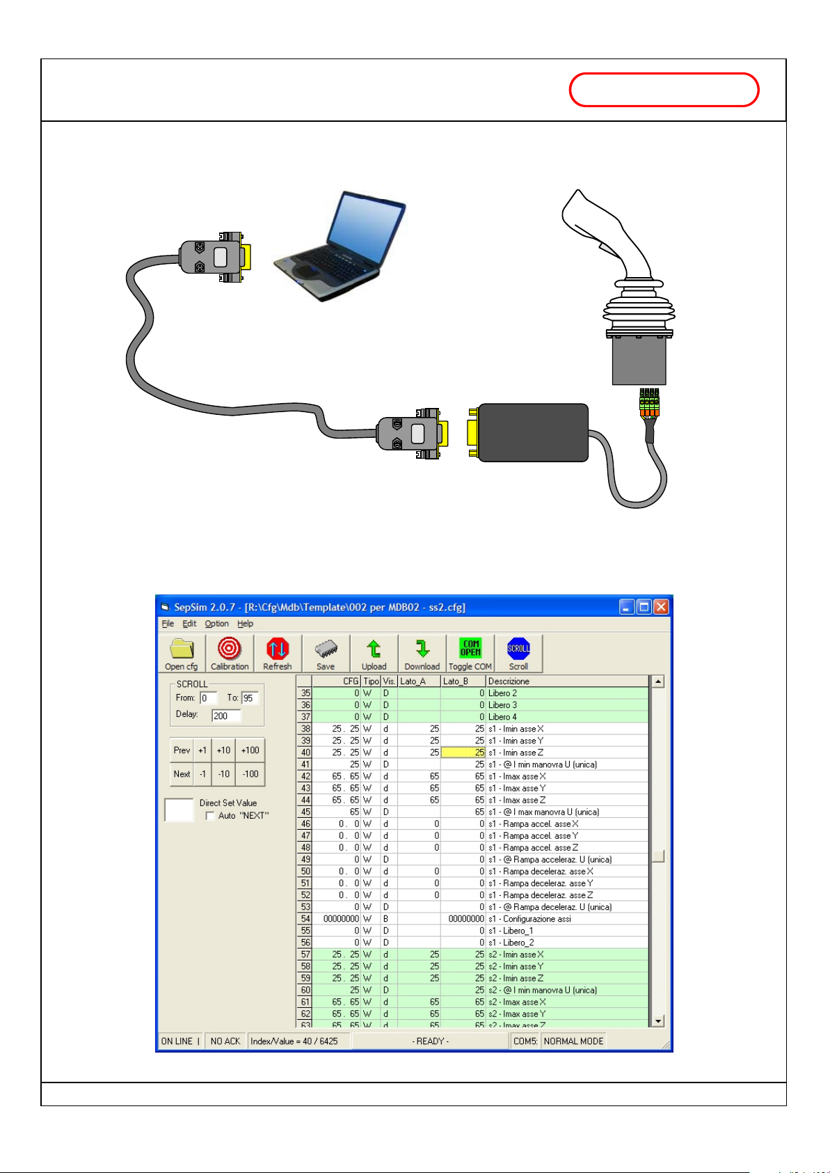
EXAMPLE OF CONNECTION TO PERSONAL COMPUTER BY SERIAL ADAPTER
with power outputs (PWM)
to the PC serial port
(or USB to RS232 adapter)
Serial cable
Serial Adapter
FABER -
JP joystick
COM
PC INTERFACE PROGRAM MAIN PAGE
FABER-COM srl - Via Romana 36/1 - 42028 Poviglio (RE) - Italy Tel. +39-0522-960428 Fax. +39-0522-969644 - www.fabercom.itFABER-COM srl - Via Romana 36/1 - 42028 Poviglio (RE) - Italy Tel. +39-0522-960428 Fax. +39-0522-969644 - www.fabercom.it
FABER-COM srl - Via Romana 36/1 - 42028 Poviglio (RE) - Italy Tel. +39-0522-960428 Fax. +39-0522-969644 - www.fabercom.it
Tecnico\Prodotti\Manipolatore\Jp\Documenti\SM#Manuale JP_v102_ie.cdr - 11/01/07
Page 7 / 8
Page 8
PRG2PRG2
Serial Programming Keyboard
FABER -
COM
DESCRIPTION
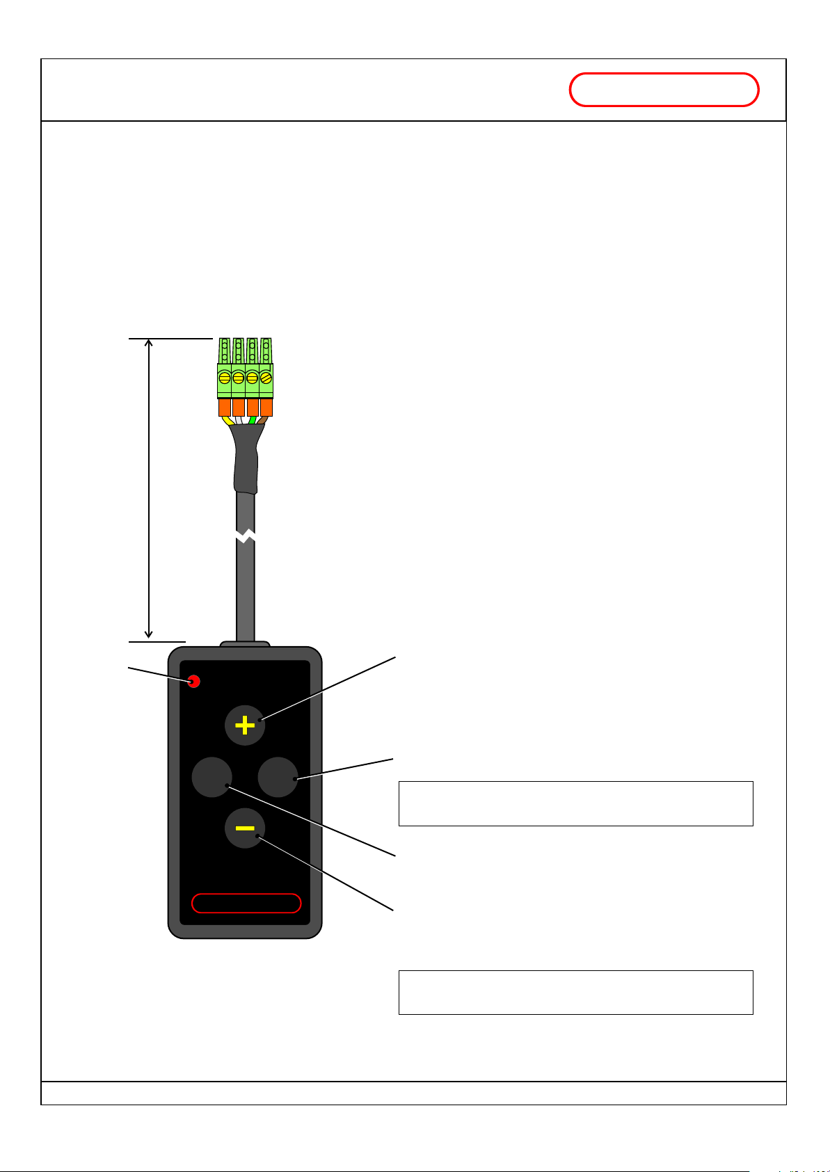
The PRG2 keyboard is the simplest device that can be used to tune working parameters of FABER-COM
microcontroller electronic cards.
With PRG2 keyboard and the help of the flashing LED on it, you will be able to scroll the working parameters and
tune them
at will.
At the end of the programming phase, it is necessary to save
parameters in memory by pushing contemporaneously the
PREV and the NEXT buttons, otherwise all the modifications
will be lost when the device will be turned off.
PRG2 keyboard connector can be plugged in and pulled out
from his socket on the electronic card even with the system
turned on.
The presence of the programming keyboard will be
automatically detected and the device will go in programming
mode.
LED
L = 50 cm
PRG2
FABER -
NEXTNEXTPREVPREV
COM
The LED shows, with a series of flashes, the current
programming step.
WORKING SPECIFICATIONS
Increase the value of the current parameter.
Go to the next parameter.
(once reached the last parameter, restart from the first)
Push PREV and NEXT together to send a SAVE
command
Go to the previous parameter.
(once reached the first parameter, stay there)
Decrease the value of the current parameter.
ACTUAL SIZE
"+", "-", "Prev" and "Next" keys have the AUTOREPEAT
function that starts 1/2 sec. after they have been pressed.
FABER-COM srl - Via Romana 36/1 - 42028 Poviglio (RE) - Italy Tel. +39-0522-960428 Fax. +39-0522-969644 - www.fabercom.itFABER-COM srl - Via Romana 36/1 - 42028 Poviglio (RE) - Italy Tel. +39-0522-960428 Fax. +39-0522-969644 - www.fabercom.it
FABER-COM srl - Via Romana 36/1 - 42028 Poviglio (RE) - Italy Tel. +39-0522-960428 Fax. +39-0522-969644 - www.fabercom.it
Tecnico\Prodotti\Manipolatore\Jp\Documenti\SM#Manuale JP_v102_ie.cdr - 11/01/07
Page 8 / 8
 Loading...