

Page 1
Manual e-MatriX 800
40011677-1742 Manual e-MatriX ENG
Page 2
Manual e-MatriX 800
--------------------------------------------------------------------------------------------------------------------------------------
2 < < < <
Registration plate:
Page 3
Manual e-MatriX 800
--------------------------------------------------------------------------------------------------------------------------------------
3 < < < <
1.0
1.1
1.2a
1.2b
Page 4
Manual e-MatriX 800
--------------------------------------------------------------------------------------------------------------------------------------
4 < < < <
2.0a 2.0c
2.0b
2.1a
2.1b
Page 5
Manual e-MatriX 800
--------------------------------------------------------------------------------------------------------------------------------------
5 < < < <
2.1c
2.2
3.0
3.1
4.0
4.1
4.2
Page 6
Manual e-MatriX 800
--------------------------------------------------------------------------------------------------------------------------------------
6 < < < <
5.0
Page 7
Manual e-MatriX 800
--------------------------------------------------------------------------------------------------------------------------------------
7 < < < <
6.0
7.0
7.1
7.2
7.3
7.4
8.0
Page 8

Manual e-MatriX 800
--------------------------------------------------------------------------------------------------------------------------------------
8 < < < <
1 General
1.1 Introduction
Only have the fire installed by a qualified installer according to the water and electric safety
regulations. Read this installation manual properly.
1.2 Check
Before installation, check the fire for transport damage and report immediately to your
supplier.
Check whether all of the parts below are included:
o Control box
o Remote
o Decoration material
o Suction cups (2x)
o Service door
o Spare transducers (2x) and absorption pill
1.3 CE declaration
Product: electric fire Opti-myst
Model: e-MatriX 800/650-I/II/III
The product complies with the European Safety Standards EN60335-2-30 and the European
Standard Electromagnetic Compatibility (EMC) EN55014, EN60555-2 and EN60555-3 these cover
the essential requirements of EEC Directives 2006/95/EC and 2004/108/EC.
!! This declaration is invalid if changes are made to the fire.
2 Safety instructions
Do not use outdoors.
Do not use in the immediate surroundings of a bath, shower or swimming pool.
Do not use without the glass installed in place.
The fire must be installed according this manual.
3 Installation requirements
3.1 Water supply
Water connection ½” or ¾” placed at an accessible location.
Water pressure on the fire between 0,5 and 8Bar. Where required, use a pressure reducing
valve.
3.2 Power supply
Electric connection -230VAC/50Hz earthed and placed at an accessible location.
Page 9

Manual e-MatriX 800
--------------------------------------------------------------------------------------------------------------------------------------
9 < < < <
4 Installation instructions
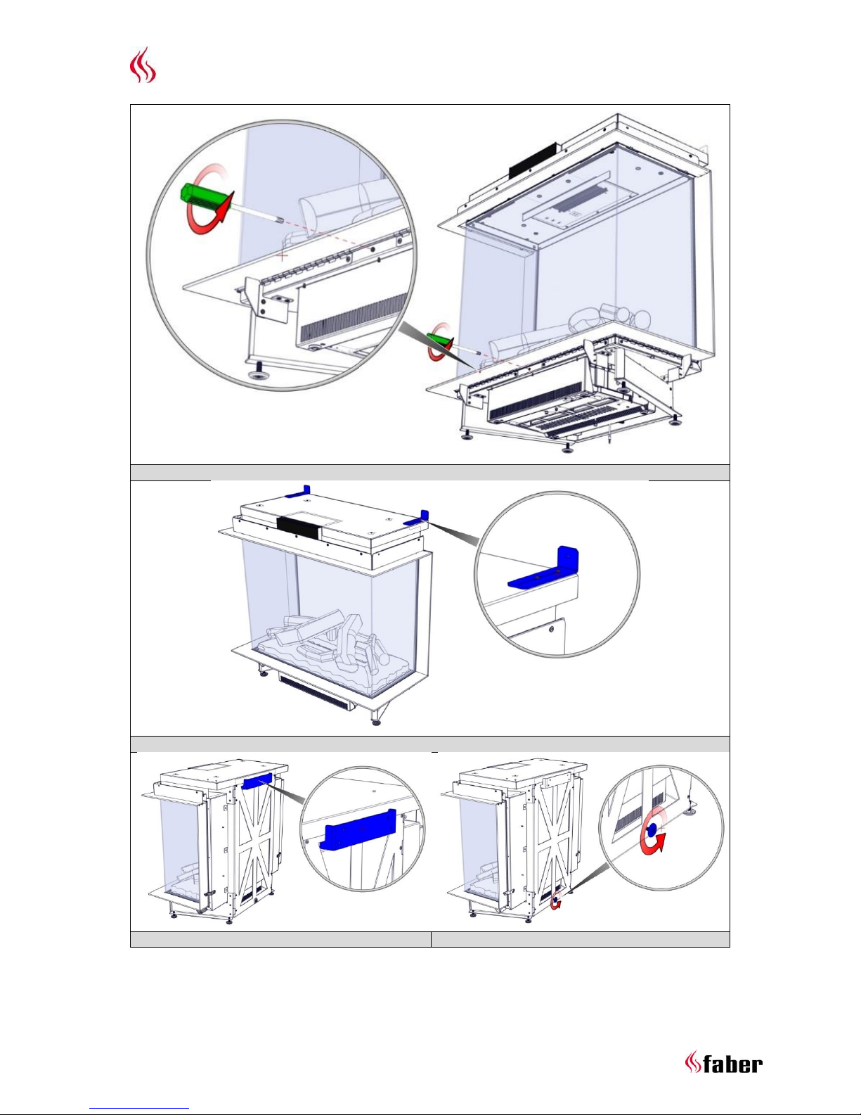
4.1 Preparing the fire
Ensure that all packing items are removed.
Remove the transport screw on the front see fig. 1.0.
Remove the front glass and store it at a safe place see Chapter 5.
Remove the fuel bed and store it at a safe place see Chapter 6.
4.2 Placing the fire
For a proper functioning of the fire, always ensure that the fire is levelled.
4.1.1 Floor standing
Place the fire at the right position and fix it on the wall see fig. 1.1.
4.1.2 Hanging on the wall
The fire can be hanging on the wall with the optional wall bracket see fig. 1.2a, 1.2b and
dimensional drawing in Chapter 13.6.
4.3 Control box
!! Place the Control box at an accessible location behind the service door.
See Chapter 13.5 and 13.7.
4.1.1 Electric connection
Use the supplied extension cable to connect the Control box to the Engine.
Lead the DC cable, inside the Engine, to the Control box and connect it.
- Max. cable length from the center of the fire to the left 1,5m.
- Max. cable length from the center of the fire to the right 1,0m.
Connect the supplied mains lead.
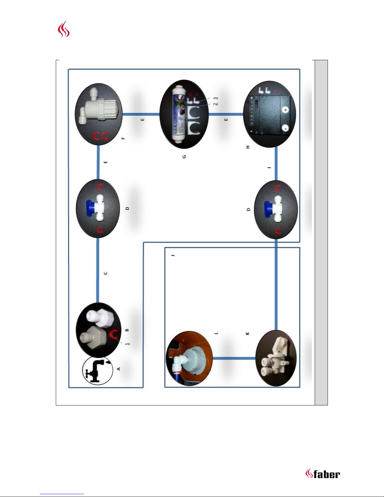
4.1.2 Water connection
This appliance is equipped with the following overflow protections:
o Electromechanical valve in the Control box which is sent by an overflow sensor in the
water tank.
o Absorption valve in the Engine that kicks in when the water sump has an
unexpectedly overflow see fig. 5.0-K.
Connect all parts according flow diagram see fig. 5.0.
A = mains water F = mesh filter 1 = safety clips (11x)
B = ½ or ¾” connector G = in-line filter 2 = in-line filter brackets (2x)
C = ¼” 1m pipe H = control box 3 = elbows (4x)
D = ball valve I = ¼” 1,5m pipe
E = to be cut from ¼” 1m pipe J = e-MatriX engine
Place the water filters at an accessible location in correct alignment, there’s a “flow”
direction marking on both filters and Control box.
!! Carry out a performance test see Chapter 9 and check all connections for water leakage before
placing the fuel bed and front glass.
Page 10

Manual e-MatriX 800
--------------------------------------------------------------------------------------------------------------------------------------
10 < < < <
4.4 Build-in structure
The e-MatriX needs a minimum ventilation of 50cm² above and 210cm² underneath the fire.
The construction may not rest on the fire.
The e-MatriX needs a minimum free space of 50mm above the fire.
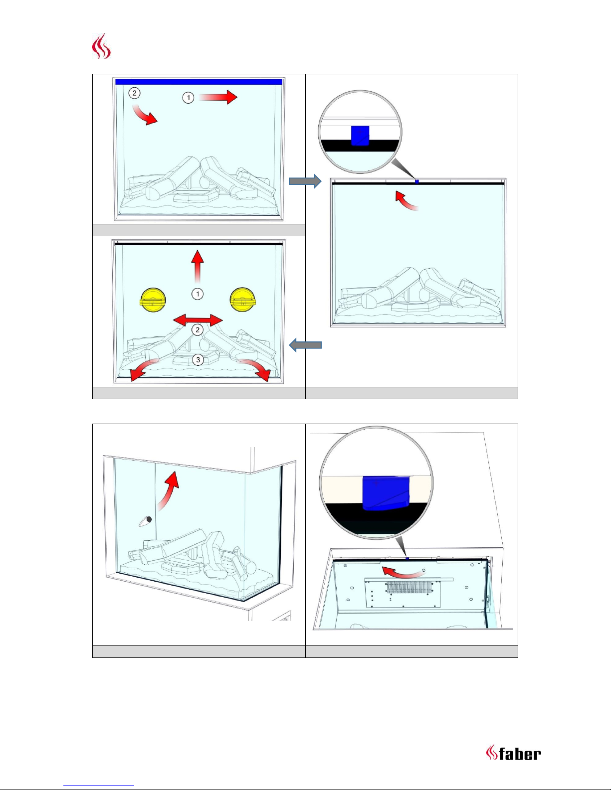
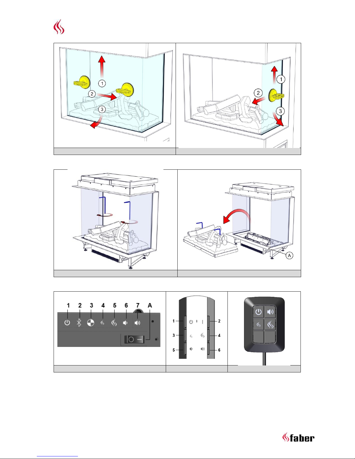
5 Removing glass
5.1 Front glass (e-MatriX front glass only)
Remove the cover strip see fig. 2.0a.
Rotate the glass clamp clockwise see fig. 2.0b.
Place suction cups and remove the front glass see fig. 2.0c.
5.2 Front glass (e-MatriX 2 or 3 sided glass)
Rotate the glass clamp clockwise see fig. 2.1a and 2.1b.
Place suction cups and remove the front glass see fig. 2.1c.
For replacing the front glass repeat the steps in reverse order.
5.3 Side glass
For cleaning only it’s not necessary to remove the side glass.
First remove the front glass see Chapter 5.1 or 5.2.
Place a suction cup and remove the side glass see fig. 2.2.
For replacing the glasses repeat the steps in reverse order.
6 Removing fuel bed
!! Never lift up the fuel bed without using the supplied handles.
!! Keep these handles for future use.
Remove the front glass see Chapter 5.1 or 5.2.
Cover the frame to avoid scratches see fig. 3.1-A.
Screw the handles in the fuel bed see fig. 3.0.
Lift up the fuel bed carefully, disconnect the plug and store it at a safe place see fig. 3.1.
For replacing the fuel bed repeat the steps in reverse order!
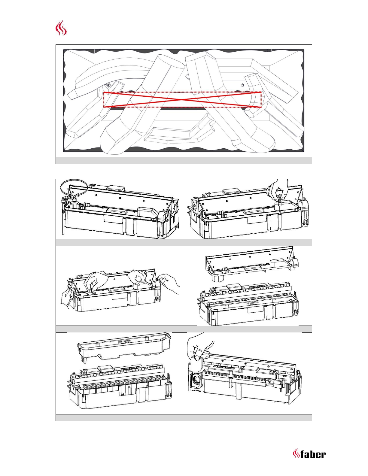
7 Placing decoration material
!! Keep decoration material away from children, persons with reduced physical or mental
capabilities and animals.
!! Don’t place decoration material in the center area see fig. 6.0.
The supplied artificial ash and chips can be used to personalize your fire!
Page 11

Manual e-MatriX 800
--------------------------------------------------------------------------------------------------------------------------------------
11 < < < <
8 Using the fire
8.1 Manual control - behind access door (see fig. 4.0)
A = main switch
1 = ON/OFF
2 = pairing
3 = only for maintenance (service engineer)
4 = reduce flame
5 = increase flame
6 = reduce fire crackling sound
7 = increase fire crackling sound
8.2 Remote control (see fig. 4.1)
1 = OFF
2 = press once for ON/press twice for glow effect only
3 = reduce flame
4 = increase flame
5 = reduce fire crackling sound
6 = increase fire crackling sound
8.1.1 Pairing the Bluetooth remote
At the Control box see fig. 4.0:
Turn the main switch in the ON position, 1 beep.
Press the button, 1 beep and the fire will begin to start.
Press the button, the fire starts to beep and the LED’s will start to blink on and off.
Press a button on the remote control. The fire will switch off. Now the remote control is paired
to the fire.
8.3 First time water fill
Ensure that all ball valves are open and turn on the water supply.
Switch the fire on by pressing the mains switch to the ON position and pressing the button
see Chapter 8.1 and 8.2.
o If the water level is high enough the flames will automatically start after 45 seconds.
o If the water level isn’t high enough the LED’s continuously to blink twice after 45
seconds. Press the mains switch to the OFF position, wait 5 seconds and repeat the
second step above (this process can be needed several times).
8.4 Getting the desired flame effect
The fire always starts with minimum flame setting. When desired press the button for
higher flames. Please give the flame generator time to react to the changes you make.
!! Increasing the flame height can lead to condensation on the glass.
Press the and button for the volume of the crackling sound to your desired level.
The minimum volume of this sound is off.
If the fire is either turned to standby or switched off entirely, it will always revert to the
minimum flame setting. The sound level will remain the same as the last sound level as set by the
user.
Page 12

Manual e-MatriX 800
--------------------------------------------------------------------------------------------------------------------------------------
12 < < < <
9 Performance test
First time water fill, see Chapter 8.3.
Check all connections for water leakage.
Check if the fan, mounted at the top inside the fire, is running.
Check if the remote control is functioning at the desired distance (max. 8m)
o If needed, move the receiver to a different position in- or outside the construction
(see fig. 4.2).
The receiver is placed at the back inside the Engine and has a cable length of 1,4m.
Replace fuel bed see Chapter 6.
Replace front glass see Chapter 5.1 or 5.2.
Perform a final functional check.
10 Maintenance
10.1 Maintenance frequency
Cleaning water sump, air filter and replacing transducers.
Commercial use: every three months.
Domestic use: once a year.
Cleaning mesh filter and replacing in-line filter.
Commercial use: once a year.
Domestic use: every second year.
!! The maintenance interval depends on the water quality and/or the running hours and therefore
can differ from the above mentioned.
10.1.1 Cleaning water sump
!! Always press the mains switch to the OFF position and disconnect the power supply see fig. 4.0.
!! Never use abrasive cleaners.
Remove the front glass see Chapter 5.1 or 5.2.
Remove the fuel bed see Chapter 6.
Disconnect the ‘fill cap’ by turning it clockwise see fig. 5.0-L and 7.0.
Disconnect the 2 connectors, located on the right side of the water sump see fig. 7.1.
Release the 2 clips on both sides and remove the nozzle see fig. 7.2 and 7.3.
Gently lift up the water sump without spilling any water see fig. 7.4.
Remove the transducers and empty the water sump.
Put a small amount of washing up liquid into the sump, and using a soft brush to clean the
sump. Also clean the transducers, including the discs underneath the cone. Remove the cone
by turning it clockwise.
When cleaned, thoroughly rinse the water sump with clean water to remove all traces of
washing up liquid.
Clean the nozzle with the a soft brush and flush out thoroughly with water.
Reverse the steps above to reassemble.
Page 13

Manual e-MatriX 800
--------------------------------------------------------------------------------------------------------------------------------------
13 < < < <
10.1.2 Cleaning air filter
Gently slide the air filter upwards out of its plastic holder see fig. 8.0.
Gently rinse with water in the sink and dry with fabric towel before returning.
Replace the filter making sure that the coarse black filter is facing the front of the fire.
Place the fuel bed see Chapter 6.
Place the front glass see Chapter 5.1 or 5.2.
10.1.3 Replacing transducers
!! Always press the mains switch of the Control box to the OFF position (see fig. 4.0) and disconnect
the power supply.
The transducers are fixed in the water sump with plastic clips.
Follow the first 5 steps in Chapter 10.1.1 to gain access to the transducers.
Press the clip back and lift the transducer upwards out of its holder.
Place the new transducers and repeat the steps above in reverse order.
10.1.4 Cleaning mesh filter
Turn off the water supply.
Close the ball valves.
Unscrew the base and clean the filter inside.
10.1.5 Replacing in-line filter
Turn off the water supply.
Close the ball valves.
Replace the in-line filter.
(Place it in correct alignment, there’s a “flow” direction marking on the filter).
10.2 Resetting absorption valve (see fig. 5.0-K)
The absorption valve is located on the right front side at the bottom of the Engine.
Take out the activated absorption pill.
Fix the cause of the water leakage and remove any water at the bottom of the Engine.
Place the new pill and open the absorption valve by pressing down the white clamp.
11 Technical data
Watts
W
250
Volts
V
230-240
Batteries remote
V
(2x) 1,5 AA
Water consumption
l/h
0,15
Inlet water pressure
Bar
0,5-8
Water connection
Inch
½ or ¾
Page 14

Manual e-MatriX 800
--------------------------------------------------------------------------------------------------------------------------------------
14 < < < <
12 Trouble shooting
Symptom
Cause
Action
The flame effect will not start.
Mains plug is not plugged in.
Low water level.
The transducers) are not connected
properly.
Check plug is connected to wall
socket correctly.
See Chapter 8.3.
Check that the connector(s) is
inserted correctly see fig. 7.0.
e-MatriX will not start or stopped
working and the LED’s continuously
to blink twice.
Low water level.
The absorption valve is activated
See Chapter 8.3.
Switch the mains switch of the
Control box to the OFF position.
Check all connections on water
leakage.
Check that the ball valves are open.
See Chapter 10.3.
e-MatriX will not operate, the LED’s
continuously to blink once every
eight seconds.
Water level too high.
Check the electromechanical valve
in the Control box.
e-MatriX will not operate, the LED’s
continuously to blink four times.
Water filling time is too long.
Switch the mains switch of the
Control box to the OFF position and
heck all connections on water
leakage.
Close the ball valves and check the
mesh filter, by unscrewing the base
of it to see that it is not clogged with
dirt and debris.
The flame effect is too low on the
highest setting.
The transducers and/or air filter are
dirty.
Call for maintenance.
The flame effect is too high and
there is too much smoke.
The extract fan doesn’t work
anymore.
Check if the fan, mounted at the top
inside the fire, is running.
Remote is not working.
Low batteries.
Remote isn’t paired to receiver.
Distance to fire too big
Place new batteries.
See Chapter 8.2.1.
See Chapter 9 (remote control).
Page 15

Manual e-MatriX 800
--------------------------------------------------------------------------------------------------------------------------------------
15 < < < <
13 Dimensional Drawings
13.1 e-MatriX 800/650-I
13.2 e-MatriX 800/650-IIL
Page 16

Manual e-MatriX 800
--------------------------------------------------------------------------------------------------------------------------------------
16 < < < <
Page 17

Manual e-MatriX 800
--------------------------------------------------------------------------------------------------------------------------------------
17 < < < <
13.3 e-MatriX 800/650-IIR
Page 18

Manual e-MatriX 800
--------------------------------------------------------------------------------------------------------------------------------------
18 < < < <
13.4 e-MatriX 800/650-III
Page 19

Manual e-MatriX 800
--------------------------------------------------------------------------------------------------------------------------------------
19 < < < <
13.5 Control box
Page 20

Manual e-MatriX 800
--------------------------------------------------------------------------------------------------------------------------------------
20 < < < <
13.6 Wall bracket
Page 21

Manual e-MatriX 800
--------------------------------------------------------------------------------------------------------------------------------------
21 < < < <
13.7 Remote access door
Page 22

Manual e-MatriX 800
--------------------------------------------------------------------------------------------------------------------------------------
22 < < < <
Page 23

Manual e-MatriX 800
--------------------------------------------------------------------------------------------------------------------------------------
23 < < < <
Page 24

www.faber.nl - info@faber.nl
Saturnus 8 NL - 8448 CC Heerenveen
Postbus 219 NL - 8440 AE Heerenveen
T. +31(0)513 656500
F. +31(0)513 656501
 Loading...