

FAB Defense GIS User Manual
Glock Scope Mount - GIS
Installation Instructions
WARNING!
Make sure your Weapon is unloaded before you begin any
assembly or disassembly procedures.
4
3
2
1
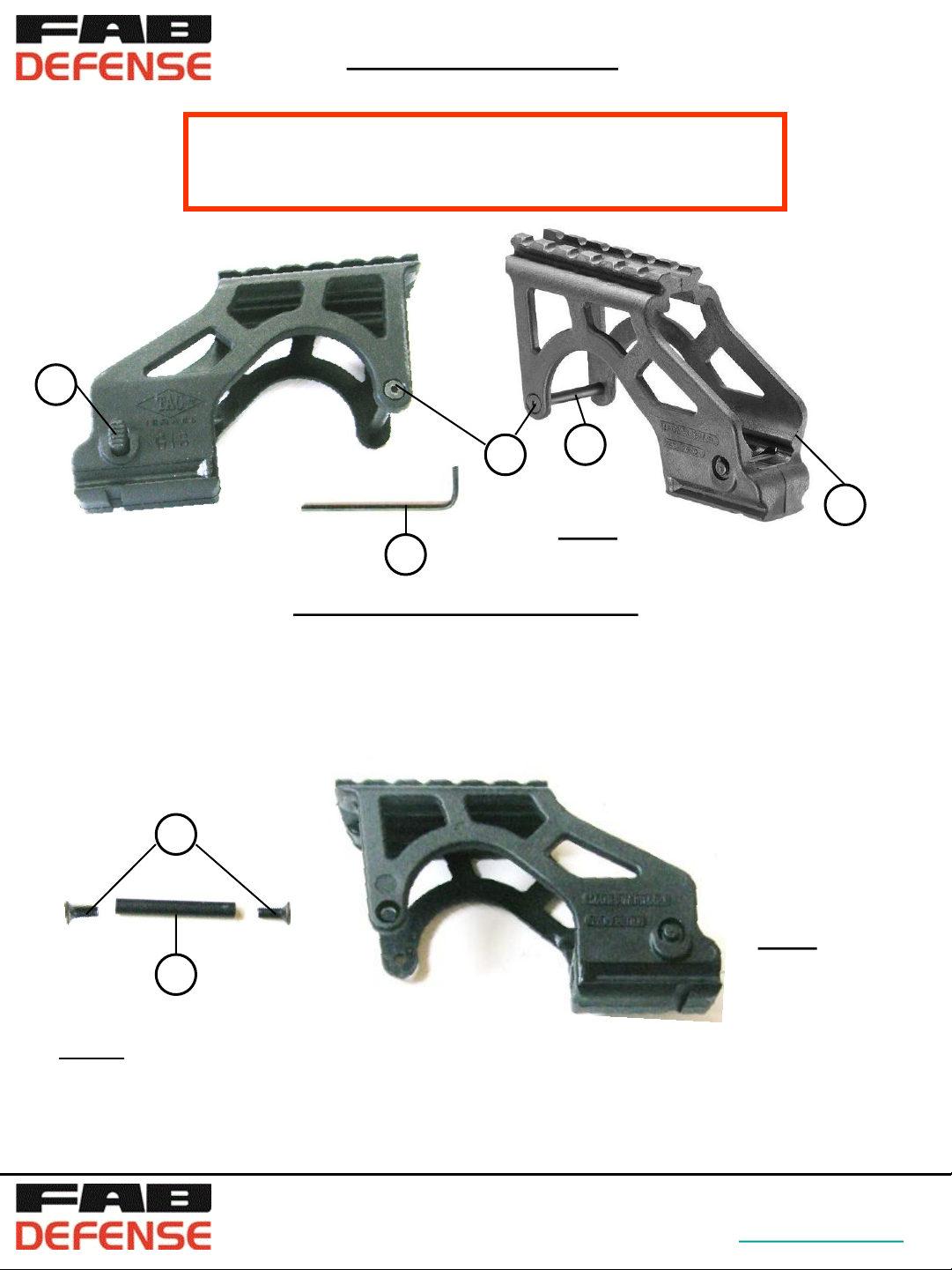
Fig. 1
5
Parts and Supplied Accessories (Fig 1)
1. Mount Assy
2. Trigger Pin
3. Securing Screws
4. Position Setting Bar
5. 2 mm Alen Key (attached)
3
Fig. 2
2
Step 1. Using the 2 mm Alen Key (5) remove from Your GIS the Securing Screws (3)
and the Trigger Pin (2) (Fig. 2).
43, Yakov Olamy St.
Mishmar Hashiva
ISRAEL 50297
Tel: +972 3 960 3399
Fax: +972 3 960 3312
defense.com-www.fabWebsite:
6
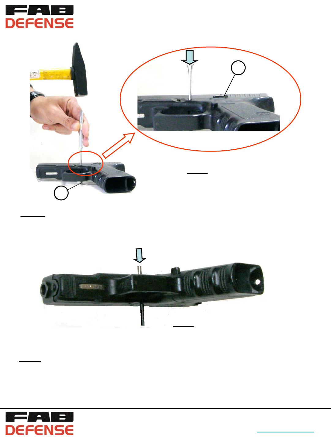
Fig. 3
7
Step 2. Put your Glock on the right side so that the Slide Stop Lever (6) is facing upwards.
Using a 3 mm Punch push slightly the Trigger Pin (7) half way out from the Slide (Fig 3).
Fig. 4
Step 3. Remove the 3 mm Punch and insert instead the GIS Trigger Pin (2) (Fig. 4).
Push the GIS Trigger Pin (2) until it is fully placed in the Receiver, replacing the original one.
43, Yakov Olamy St.
Mishmar Hashiva
ISRAEL 50297
Tel: +972 3 960 3399
Fax: +972 3 960 3312
defense.com-www.fabWebsite:
 Loading...