

Page 1

Page 2

Page 3

INTRODUCTION
This operator is intended to be installed on vehicular Class I, II, III or IV gates as defined by UL 325.
Maximum gate load not to exceed 400 pounds and 13 feet in length.
PLEASE READ THIS ENTIRE MANUAL CAREFULLY PRIOR TO INSTALLATION.
The Ranger control board was designed with a current sense safety feature and we strongly recommend other
safety devices such as photo eyes to make each particular installation as safe as possible and reduce the risk of
personal injury and/or property damage.
Please read carefully and understand the Safety Section of this manual.
Cautions - Very Important
¾ Do not attempt to enter the gate area while the gate is moving. Wait until the gate comes
to a complete stop.
¾ Operate the gate only when it is fully visible, free of persons or obstructions, and
properly adjusted.
¾ Do not allow children to play in the area of the gate. Do not allow anyone to ride on the
gate.
¾ Do not allow children to play with the remote control or any other activation device.
¾ Do not attempt to "beat the gate" while the gate is opening or closing. This is extremely
dangerous.
¾ Test the current sense feature and all safe ty devices regularly to insure correct operation.
¾ Study the entire Safety Section (page 23-24), paying particularly close attention to the
Entrapment zones on page 24 and be aware of these areas no t only during use but also
during any adjustments to the unit.
¾ The USAutomatic battery charger is designed to operate with a +12 vd c battery, sealed
maintenance free type Group U-1 battery recommended. 33 amp hour minimum.
¾ All control stat ions should be located at least 6 feet from any mo ving part of the gate o r
operator.
¾ Do not ever install any control device where a user will be tempted to reach through the
gate or fence to activate a gate.
¾ Do not attempt to completely seal the control box.
BATTERY REQUIRED FOR OPERATION (Battery not included)
Recommended battery type
Battery 12-volt, Group U-1; sealed (maintenance free); 33 amp hour minimum.
The Plug N Go harness has two 1/4” ring terminals to connect to bolt type battery post.
CAUTION: Do not install wet cell battery into control box; this type of battery usually
has removable caps used for service and will vent into control box.
© USAutomatic, LTD, 2008 rev. N/C
All rights reserved. No part of this may be reproduced by any means
without the expressed written consent of the publisher.
USAutomatic Part Number 720104
1
Page 4

Table of Contents
Page
Introduction and Recommended Battery Type ...................................................................... 1
Table of Contents ............................................................................................................. 2
Importance of a Properly Designed Gate / General Requirements ........................................... 3
Parts Included .................................................................................................................. 4
Gate Qualifications / Applications ...................................................................................... 5
Ranger Gate Opener General Information and Special Features .............................................. 5
Ranger Gate Opener Information Solar Charged ................................................................... 5
Understanding AC Charged System / Solar Charged System ................................................... 5
Gate Cycles per Day AC charged / Solar Charged / Solar Region Map .................................... 6
Mounting Site Review / Ranger Installed Photo ................................................................... 6
Installing Actuator Support Bracket / Installing Actuator Bracket .......................................... 7
Installing Actuator to Actuator Bracket ............................................................................... 7
Installing Gate Bracket to Actuator .................................................................................... 8
Attaching for Push to Open Installation .............................................................................. 8
Installing Gate Bracket to Gate (Pull to Open) and (Push to Open) ......................................... 8
Preparing Ranger Control Box for Installation ..................................................................... 8
Installing Ranger Control Box ........................................................................................... 9
Splicing for Ranger 500 S Linear Actuator Cable if Needed .................................................. 9
Ranger Quick Connect Harness Initial Installation ............................................................... 9
Ranger Battery Installation ................................................................................................ 10
Determining Charger Location (AC or Solar) / Solar Panel Installation ................................... 10
Optimizing Solar Panel Location ........................................................................................ 11
Transformer Installation / Connecting Charge device to Charge Controller .............................. 11
Charge Controller Operation Check .................................................................................... 11
Charge Controller / Transformer Manufacturer Information ................................................... 12
Linear Actuator Cable Connection ...................................................................................... 13
Ranger Quick Connect Harness Final Installation ................................................................. 13
Understanding Sensitivity Adjustments and Entrapment Alarm .............................................. 14
Adjusting Gate 1 and Gate 2 Sensitivity .............................................................................. 14
Understanding Close and Ope
Operating Gate for the First Time / Making Final Adjustments .............................................. 14
Installing Safety Signs ...................................................................................................... 15
Adjusting Close Limit Utilizing Nudge Technique ................................................................ 15
Ranger Control Board / J2 Terminal / Control Switches Function ........................................... 15
Ranger 500 D Gate 2 Kit Installation .................................................................................. 16
Installing Gate 2 Linear Actuator and Junction Box ........................................................... 16-17
Connecting Gate 2 Actuator to Control Board ...................................................................... 17
Operating Gate 2 for the First Time and Final Adjustments ................................................... 17
Programming Transmitter and Receiver ............................................................................... 18
Programming Wireless Keypad ........................................................................................ 19-20
Optional accessory information, Garage receiver, Push to operate button, 7 day timer .............. 21
Optional accessory information, Photo Eye Installation / Wiring ............................................ 22
Safety Section .............................................................................................................. 23-24
Periodic Service ............................................................................................................... 24
Troubleshooting Guide ................................................................................................... 25-27
Accessory Wiring Information ........................................................................................... 28
Warranty Statement .......................................................................................................... 29
n Limit Adjustments ............................................................... 14
2
Page 5

IMPORTANCE OF A PROPERLY DESIGNED GATE.
USAutomatic, LTD is not responsible for any damage to a gate in which the gate operator is installed. A
poorly installed or misadjusted gate could be damaged. It is the responsibility of the installer to verify proper
gate installation prior to operator installation.
As a general rule a gate which is to be automatically operated must be stronger and smoother than one which
will be manually operated. Since the gate is a major component of the system, great care and concern must be
given to the gate design.
NOTE: A GATE OPERATOR CANNOT OVERCOME A POORLY DESIGNED GATE.
A. Does the gate swing smoothly without binds or excessive resistance? Swing gates should swing level and
plumb to prevent the operator from having to lift the gate open or closed. Swing gates should not require
a wheel to support them. Wheels create drag, which will cause operator problems. A wheel is generally a
sign of a weak hinge system or a weak gate frame.
B. Is the gate frame of substantial strength without excessive weight? Will the frame withstand normal wind
load conditions without sway or vibration? Will the gate close correctly without being hand-guided or
lifted to close?
C. Are the hinges suited for an automatic gate operator? We recommend bearing type hinges to reduce
friction drag.
D. Will a reinforcement brace be required to attach the linear actuator to the gate or does a suitable cross
member exist in the gate design?
If any of these problems exist, they must be corrected to achieve a reliable automatic gate system.
GENERAL REQUIREMENTS
Tools required for most installations:
Wrenches & Socket – 9/16
Drill
Level and tape measure
Drill adapter for socket attachment
Pliers
Hack saw
Welding is the recommended method of securing the linear actuator mounts to the gate and hinge post. Bolt on
brackets are optional, but may require frequent service to keep tight. They must be very securely attached (i.e.
carriage bolts with lock nuts and washers). Lag type bolts are not recommended. Loose or unstable linear
actuator mounts will result in improper operation.
IMPORTANT CAUTIONS:
1. Do not perform any welding with the actuator cable plugged into the control board or the battery
connected. Serious damage to the control board and/or battery may occur if attempted.
2. Use control box as a template to determine mounting screw locations and then attach screws and slide on
control box. Do not attempt to hold control box and drill mounting holes this could damage the preinstalled
components.
3. Always disconnect the battery power from the control board using the Quick connect harness prior to
wiring any devices to the control board.
3
Page 6
PARTS INCLUDED Ranger 500 S part number 020510
Ranger Actuator
Bracket Pro
Part # 610420
Ranger Actuator
Support Bracket Pro
Part # 610425
3/8 x 16 serrated hex nut
Part # 610518
1 per
3/8 SAE flat washer
Part # 610516
2 per
#12 Self tap hex screw
Part # 610532
4 per
Bronze Bushing
Part # 610530
2 per
Manual release pin
Part # 610534
1 per
Manual release clip
Part # 610535
1 per
Transmitter
Part # 030210
2 per
Quick Connect harness
Part # 630040
1 per
Transformer
Part # 520008
1 per
LCR Receiver Part # 030200
Charge Controller Part # 520007
Ranger Charge cable Extension
Part #
Ranger External Reset Cable
Part # 630060
4
Linear Actuator
Part # 510300
1 per
Control Board Part # 500500
Gate Bracket
Part # 610110
1 per
3/8 x 2 ½” shoulder bolt
Part # 610512
1 per
Nylon washer
Part # 610528
2 per
Entrapment Siren
Part # 530015
1 per
½” Cable gland
Part # 620022
1 per
Safety Sign
Part # 601027
2 per
Ranger Control Box Assy
Part # 020570
Page 7

GATE QUALIFICATIONS/APPLICATIONS
The Ranger gate operator is designed and rated for vehicular class I, II, III or IV swing gates up to 13 feet in
length. Recommended for Gates that meet the following descriptions:
The Ranger gate operator is designed and supplied with weld on mounting brackets to fit most types of gate
installations. If desired, optional bolt on brackets are available (part # 620151) for hinge post from 2 3/8” to
6” round or square.
Ranger Gate Operator General Information and Special Features
The Ranger gate operator is powered by a 12 VDC battery (not included). This battery is charged by the
supplied transformer which requires AC power (120 VAC) to be either at the gate area or within 1000 feet of
the gate area. If the AC power is more than 10 feet from the gate operator control box then additional
extension cable is required (see page 10 for Ranger charge cable extension kit information).
If preferred with the optional Ranger Solar Panel kit, you may use a solar panel to charge the battery.
Typically only one panel will be required. The Ranger gate operator is capable of a high number of cycles
per day. For information on what you can expect from a solar charged system see page 6. Accessories that
are added to your gate operator must be solar friendly accessories and they will be identified as such.
Visit www.usautomatic.com for more information and design assistance.
The Ranger gate operator features Quick connect wiring harness that eliminates the need for any complicated
wiring. The only wiring required consists of two wires from the harness that must be connected to the battery
positive (red wire) and negative terminals (black wire). All components have been pre-installed so that
installation can typically be completed in less than one hour.
The Ranger control board features high quality components and industry leading ideas such as auto resetting
fuses for motor protection. The old auto type fuse that blows and must be replaced has been designed out of
this control board to avoid the unnecessary expense of buying fuses. Patent pending on board limit
adjustments are a first in the industry and make limit adjustments easy if needed.
The standard LCR transmitter and receiver package offer the customer many advantages. The solar friendly
receiver design, two output channels, excellent operational range and the ability to store up to 42 individual
transmitter dip switch settings make this product superior. The wireless keypad design allows for 2 to 5 digit
access codes and memory is retained, if battery is removed. USAutomatic strongly recommends this package
to reduce the possibility of premature battery drain that may be caused by other receiver packages.
Garage door compatibility is possible using “Garage Door Receiver” (part # 030214). It is easily installed by
connecting 2 wires.
Understanding AC Charged System
The Ranger gate operator comes with a low voltage transformer which plugs into the charge controller and
can easily provide 575 cycles of operation a day without decreasing the battery charge. In the event AC power
goes out the operator will operate for weeks on the battery (if cycles per day are below 20) before needing
service. Again, accessories connected to the operator are critical. Always use Solar Friendly accessories to
help avoid premature battery failure in cases of power outages.
Understanding Solar Charged System
The Ranger gate operator is designed to provide enough cycles a day for most installations without needing
more than one solar panel. Care must be taken to ensure the solar panel has full sun throughout the day; partial
sun will give partial results. If no sun is present then a solar system is not practical no matter how many
panels might be installed. Solar Panel must be kept clean and in full sunlight.
The design of the system must pay particular attention to any accessories that might be added, use
only Solar Friendly accessories to help avoid premature battery failure. For a complete list of
accessories please visit www.usautomatic.com.
5
Page 8

GATE CYCLES PER DAY AC CHARGED SYSTEM (TRANSFORMER INCLUDED)
AC charged systems should not exceed 575 cycles per day.
GATE CYCLES PER DAY SOLAR CHARGED SYSTEM (OPTIONAL SOLAR KIT)
Solar charged systems should not exceed the cycles listed in the chart below. These numbers are based on a
single 6 watt solar panel installation. If additional panels are installed additional cycles will be available.
Model Type
Ranger 500 S single gate
Ranger 500 D dual gate
REGION 1 REGION 2 REGION 3
10 cycles per day 40 cycles per day 60 cycles per day
5 cycles per day 20 cycles per day 40 cycles per day
Region 1 covers the area of the country receiving the least amount of solar radiation. On average the amount
of charge time is 1.5 hours in region 1, 3 hours in region 2 and 5 hours in region 3.
Figure 1
Region 1
Hours of Solar Radiation 1.5
Region 3
Hours of Solar Radiation 5
Region 2
Hours of Solar Radiation 3
These are conservative numbers and the Ranger gate operator should have no problem performing as stated in
the chart above. See Region Map (figure 1) to determine cycles that can be expected. These numbers are
based on a basic system with the standard 6 watt solar panel and adding solar friendly accessories will not
have any great affect on the numbers stated. Using other accessories can cause premature battery failure. Look
for the solar friendly logo when considering accessories for your gate opener.
MOUNTING SITE REVIEW
Review the items below prior to installation and predetermine the solution to any problems which may exist.
A. Does sufficient space exist for mounting and future servicing of the operator and control box?
B. Which direction will the gate swing?
Will the gate operator pull the gate open to the inside (Pull to Open)?
Will the gate operator push the gate open to the outside (Push to Open)?
C. Where will the actuator bracket and gate bracket be secured at the hinge post and to the gate ?
D. Where will the control box be mounted to support the weight of the battery and can it be located within
8 feet to prevent splicing of the actuator cable?
E. How far away is the 110 VAC receptacles for the transformer? Transformer is supplied with 12 feet of
cable, if extension is needed use Charge Cable Extension pig tails included. See page 10 for charge
extension information and recommended wire size chart for extension distance needed.
F. Where will the solar panel mount if solar charged so that optimum sunlight is received? Solar panel in
most cases needs to face a south west direction. Solar panel comes with 15’ of cable if extension is
needed use Charge Cable Extension pig tails included. See page 10 for charge extension information
and recommended wire size chart for extension distance needed.
G. How will accessory control wiring, if any, be brought to the control box? Knock outs are provided in
control box bottom for conduit.
H. Have all safety concerns been addressed? (See Safety Section Page 23-24)
6
Page 9
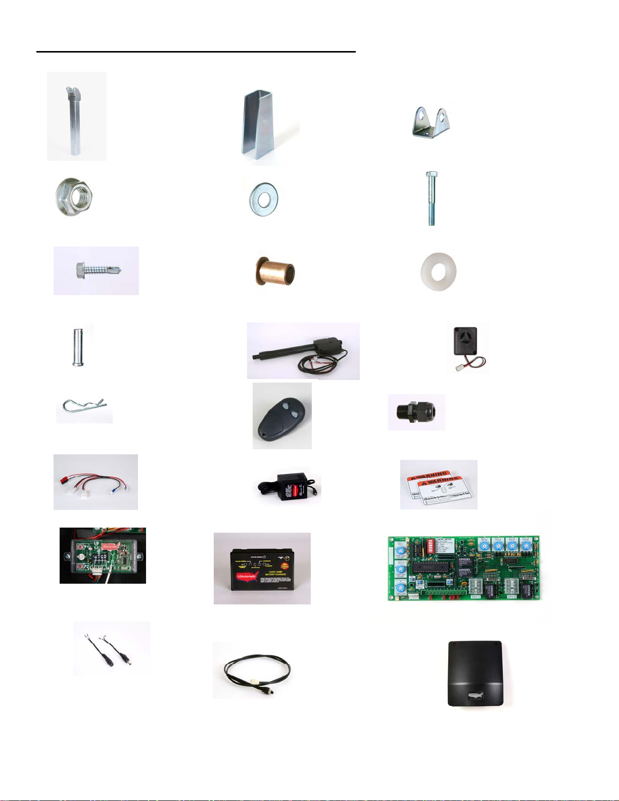
Installing Actuator Support Bracket & Actuator Bracket (Pull To Open)
*Bolt on brackets shown optional
The picture in figure 2 is a Pull to Open installation. When
determining the location of the actuator pivot point all
measurements should be made from the center of the hinge.
The dimensions for a typical 90 degree ope ning are 5” behind the
7”
hinge center and 7” toward the inside of the property.
Measurements are from hinge center, there are many types of hinges available.
Make measurements from the hinge center.
Actuator pivot point
5”
Actuator pivot point
Ranger actuator support bracket and actuator
bracket are standard and require welding to install
Figure 2
Gate shown in the full open position
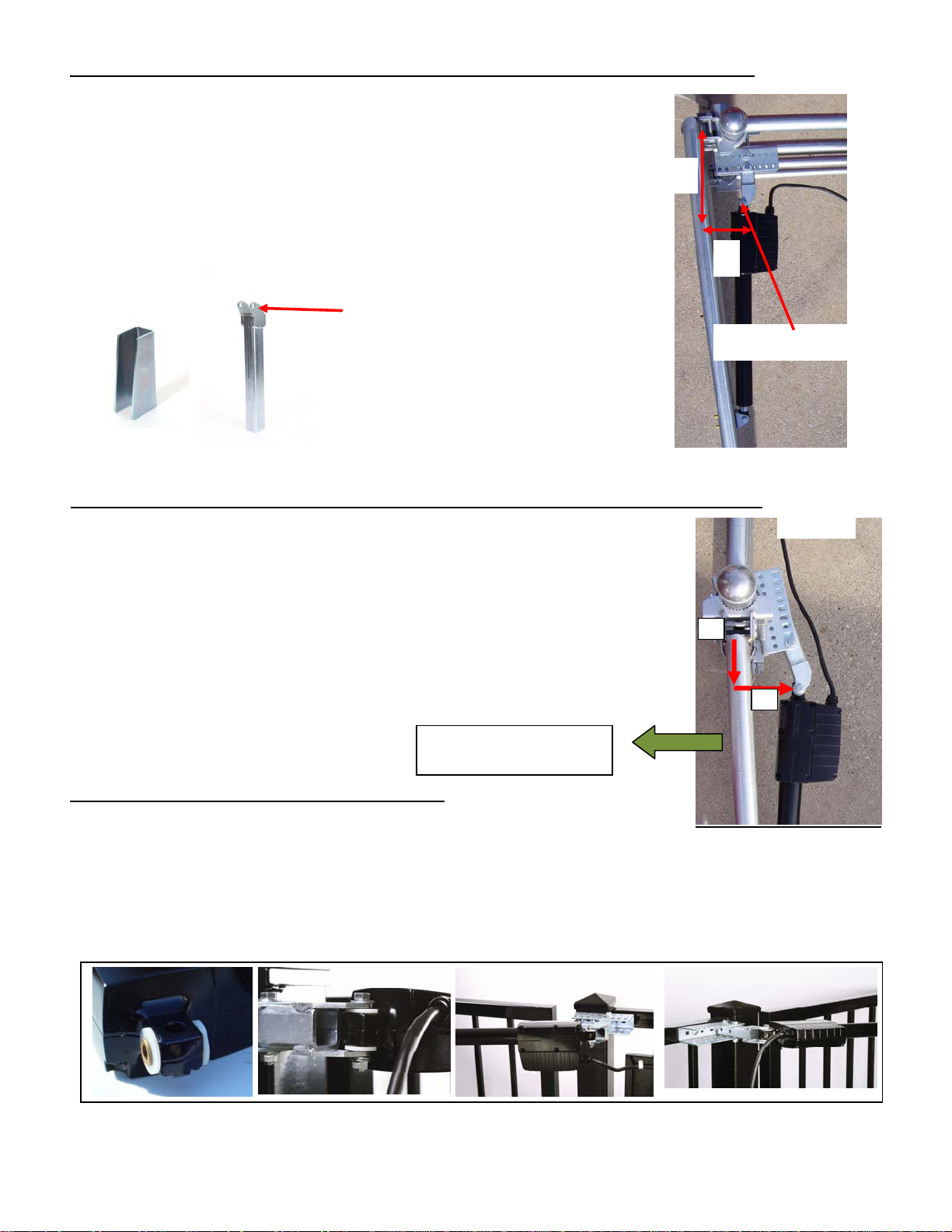
Installing Actuator Support Bracket & Actuator Bracket (Push To Open)
*Bolt on brackets shown optional
The picture in figure 2A is a Push to Open installation. When determining
the location of the actuator pivot point all measurements should
be made from the center of the hinge.
The dimensions for a typical 90 degree ope ning are 4” behind the
hinge center and 7” toward the driveway from hinge center. This
7”
type of installation places the bracket out slightly toward the
drive.
Shown in Closed position
Direction of gate
movement when opening
Installing Linear Actuator to Actuator Bracket
See figure 3 (Bolt on brackets shown are optional)
1. Install nylon washers and bronze bushings into rear of linear actuator.
2. Install into actuator bracket
3. Secure in place using 3/8 x 2 ½” shoulder bolt and two 3/8 SAE washers.
4. Use 3/8 serrated hex nut to secure, tighten firmly. Do not over tighten.
Important: Actuator should swing freely, Do not over tighten.
Figure 3
Figure 2A
4”
7
Page 10
d
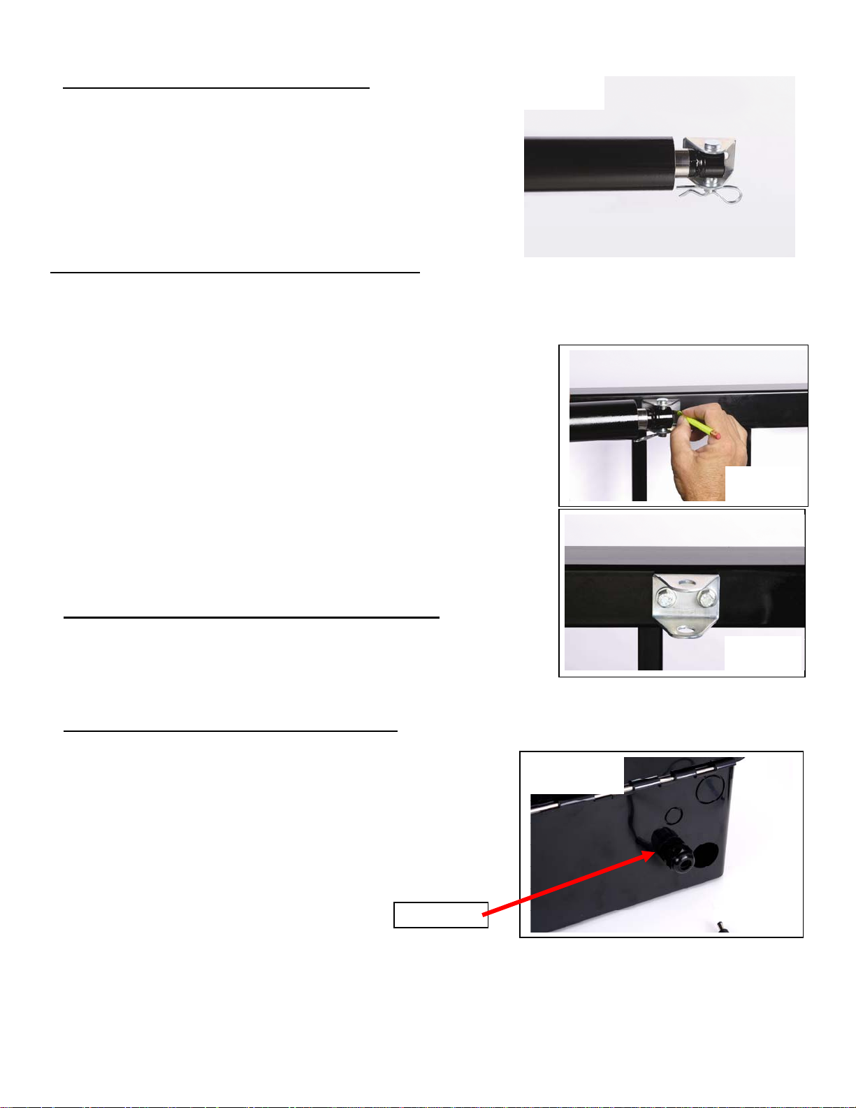
Installing Gate Bracket to Linear Actuator
Figure 4
See figure 4
Install manual release pin, gate bracket and manual release clip
to linear actuator extension rod end.
Installing Gate Bracket to Gate (Pull to Open Only)
Important: The linear actuator was shipped from the factory set to the fully retracted position. To determine
where the gate bracket will be installed follow the steps below:
The linear actuator should be connected to the actuator bracket at this point.
1. Swing gate to the fully open position.
2. Now open gate another couple of inches (the gate will never open
more than this position). The gate can be adjusted later to open a
little less if needed.
3. Swing linear actuator around (should swing freely) in a level
position to meet the fully open gate. This is where the gate bracket
should be installed on the gate.
4. There are 2 - ¼” holes in the bracket. They can be used to screw the
Figure 5
bracket to the gate before welding if desired (see figure 5 & 6).
5. The gate should now be installed in the fully open position. Verify
that linear actuator is level and all pieces have been installed
correctly.
Installing Gate Bracket to Gate (Push to Open Only)
Procedure is identical to the steps for Pull to Open except the gate will
be in the fully closed position.
Preparing Ranger Control Box for Installation
The control box has two holes in the bottom of the box providing
access to the wire compartment. The large hole is for the actuator
cable and the smaller hole is for the charge device cable.
Install the provided cable gland into the small hole as shown in
figure 7.
Cable Glan
Figure 6
Figure 7
8
Page 11

Installing Ranger Control Box
The control box should be installed in a location that will not require the eight foot linear actuator cable to be
spliced. If the cable must be spliced refer to splicing instructions below.
Avoid placing the control box behind solid metal objects that might interfere with the receiver reception. The
antenna for the receiver is located inside the control box and this could reduce the operating range.
The control box has 4 mounting holes shown in figure 8, use 4 #12 hex head self tapping metal screws to
securely mount the control box. Verify the structure control box is mounted
on is sufficient to hold the control box and battery securely.
Figure 8
Install control box at this time.
Mounting Holes
4 Places
Splicing for Ranger 500 S Linear Actuator Cable (if needed)
The Ranger linear actuator comes with 8 feet of cable. Avoid splicing this cable if
possible. If the control box must be located in such a way that splicing is required
follow the guidelines below to avoid problems.
1. Locate the linear actuator 8 pin connector. Measure 18” from connector and mark.
2. Cut cable at the 18” mark. This will allow enough cable to be spliced and placed in the wire compartment.
3. Bring extension cable into control box and splice 5 wires using wire nuts.
4. Use approved weather tight electrical junction box for the splice located outside the control box.
5. Conduit should be used between junction box and control box. Control box knock out is for ½” conduit.
6. The extension cable must consist of 5 wires, 2 fourteen gauge wires and 3 eighteen gauge wires.
¾ Red wire with white stripe – 14 gauge (distance added is greater than 50 feet use 12 gauge)
¾ Black wire with white stripe – 14 gauge (distance added is greater than 50 feet use 12 gauge)
¾ Orange wire – 18 gauge (distance added is greater than 50 feet use 16 gauge)
¾ Green wire – 18 gauge (distance added is greater than 50 feet use 16 gauge)
¾ White wire – 18 gauge (distance added is greater than 50 feet use 16 gauge)
7. With extension cable now in the junction box strip and prepare to splice to linear actuator cable.
8. Route linear actuator cable into junction box and splice using wire nuts.
NOTE: Cable splice must be water tight to keep moisture away from splices and prevent problems.
Ranger Quick Connect Harness Initial Installation
Attach the quick connect harness to the charge controller prior to installing
the battery. Plug the charge controller connector into the bottom of the
charge controller (see figure 9). Plug is color coded. Once connected place
harness into wire compartment to prepare for battery installation.
Charge controller connector
Figure 9
Figure 10
¼”Ring terminal for battery
Black connects to negative battery post
Red connects to positive battery post
Gate 1 and Gate 2 linear actuator power plugs
9
Page 12

Ranger Battery Installation
Battery recommended is a sealed, group U-1 12 VDC battery.
This battery is sometimes described as a lawn tractor battery.
Battery physical size must not exceed 9” wide, 7” tall and 5 ¾” deep.
Install the battery into the battery compartment.
Connect harness as shown in figure 11.
Connect ¼” ring terminals from harness to the battery.
NOTE: Red wire to positive post of battery
Black wire to negative post of battery
Tighten the bolts securely (bolts normally are supplied with the battery)
Figure 11
Determining Charge Device Location (AC or Solar)
The USAutomatic charge device being used is equipped with a DC plug for easy connection to the charge
controller. Loosen cable gland nut and route the cable from the charge device into the control box (see figure
14). Ensure that DC plug can reach the charge controller “Power In” connector.
Tighten cable gland nut to hold cable in place.
NOTE: If charge device cable needs to be extended to reach the charge controller use the charge cable
pig tails included (see figure 12). If splice is outside use junction box, DC plug pigtails and wire
nuts. Use charts below to determine wire size needed for the distance to be extended. The cable
must be a 2 conductor cable, stranded wire recommended.
Do not modify the transformer or solar panel cable, this will void the product warranty.
Splice mate for the charge controller to cable end located in control box.
Figure 12
Splice mate for the charge device to cable end that connects to charge device.
Junction box should be used to keep external connections dry. (see figure 12).
Charge Cable Extension Cable Selection Chart
Transformer Extension Wire Size Chart
0 to 100 feet 101 to 250 feet 251 to 500 feet 501 to 750 feet 750 to 1000 feet
18 gauge wire 16 gauge wire 14 gauge wire 12 gauge wire 10 gauge wire
Solar Extension Wire Size Chart
15 to 100 feet 100 to 250 feet 250 to 500 feet
16 gauge wire 14 gauge wire 12 gauge wire
Solar Panel Installation: Optional Solar Panel Kit Part Number 520021
The location of the solar panel is critical for proper battery charging. The panel needs to face a Southwest
direction and be installed at the angle of the supplied solar panel bracket. For proper operation the panel must
have unobstructed sun.
Figure 13
Linear actuator cable
Cable Gland for charge device cable
Figure 14
10
Page 13

Optimizing Solar Panel Location:
The charge controller determines the charge method installed (AC or Solar) and charges the battery at the
optimum charge rate. The solar panel outputs voltage and current to charge the battery. This output voltage
will vary slightly as the sun passes over throughout the day. The charge controller can be used to optimize this
output voltage.
¾ To use this feature identify time of day for the maximum solar radiation (typically around 2 pm).
¾ Face the panel toward the sun and observe the “External Power” light on the charge controller, adjust the
panel until light comes on and secure in that position.
NOTE: Depending on the time of year and your exact location the output voltage required to illuminate
“External Power” light may not be possible. This does not indicate a problem. In this case set
panel to face a Southwest position and verify “Solar Power” light is on. Battery is being charged.
Transformer Installation: (supplied with operator)
The transformer supplied is a low voltage UL approved transformer for this type of application.
If replacement becomes necessary replace with USAutomatic part # 520008
Failure to use the proper transformer can damage the charge controller.
Connect the transformer to an approved electrical receptacle.
NOTE: T
he 110 VAC receptacles should be installed by a qualified electrician, per local building codes.
Do not modify the transformer cable, this will void the warranty.
Connecting Charge Device to Charge Controller: (Transformer or Solar Panel Kit)
The Ranger gate operator charge controller accepts inputs from either the supplied AC transformer or the
optional solar panel. The transformer and solar panel come with a DC plug for easy installation. Once the
charge device is selected and installed connect the DC plug into the charge controller “Power In” located in
the upper right corner of the charge controller (see figure 15).
Charge device plugs in here
Figure 15
Charge Controller Operation Check
Once the charge device is plugged into the charge controller identify your installation below. Verify proper
operation by observing lights on charge controller as stated on page 12.
NOTE: Most batteries will not be completely charged when first connected and the charge light should
come on when charge controller is first connected. The fully charged light will come on once battery is
fully charged.
The charge controller is designed to only charge the battery when there is enough sun to do so. If there is no sun
then the lights on the charge controller should be “OFF”. If transformer is installed lights are operational all the
time. This feature reduces the drain on the battery in solar installations.
11
Page 14

1. L.E.D. DISPLAY
First 3 seconds upon Charger/Controller powered from Battery or Supplied
Power Supply, the Battery Status Light Emitting Diode (L.E.D.) Flashes.
1.1. L.E.D. Description
EXTERNAL Illuminates continuously while power from A.C. Power
POWER Supply Adaptor is sensed.
ADAPTOR
SOLAR Illuminates continuously while power from Solar Panel
PANEL is sensed.
DETECTION If illuminated for longer than 2 seconds check connection
on battery.
CHARGING Continuous or flashing indicates charging – refer to Charge
Algorithm Section, for further details.
CHARGED On continuously when AC present and battery fully
charged. Flashes when battery capacity is low.
SYSTEM ERROR If flashing, the charger has entered Failure Mode.
Disconnecting power will reset charger, but if source of
failure is not corrected, Failure Mode will occur again.- refer
1
to the following Table to Decode the Error Type:
L.E.D.s (First 4 L.E.D.s from Left)
st
2nd 3rd 4th
Wrong Battery Voltage Off Off Off Flash
Reverse Battery Connection Off Off Flash Off
Thermal Runaway Condition Off Flash Off Off
Charge Time Monitor - 1 Off Flash Flash Off
Charge Time Monitor - 2 Off Flash Flash Flash
Excessive Battery Drain Flash Off Off Off
Failed Pre-Qualification Test -1 Flash Off Off Flash
Failed Pre-Qualification Test -2 Flash Off Flash Off
2. POSSIBLE REMEDIES TO FIX ‘FAILURES’
WRONG BATTERY VOLTAGE
Example: Charger connected to a 24v battery. Reconnect to a battery
rated at 12Vdc.
REVERSE BATTERY CONNECTION
Check and correct any reverse battery.
THERMAL RUNAWAY CONDITION
Old Battery - cells, inside battery, age differently. During charging, and
over the course of many years of operation, OR, many battery
discharges to levels beyond 100% discharged, this error may occur
and the battery(s) may have to be replaced.
CHARGE TIME MONITOR – 1 and 2
Battery pack took too long to complete its charge. Possible causes
include a load (gate cycling repeatedly for a long period of time) during
charging or the battery pack is too large (Many batteries connected in
a parallel circuit). Apply the following formula to determine if the Timer
may run out due to a large battery:
Charge Time = Battery Capacity (AH)
x 1.25
2
Calculated Charge Time must be less than approximately 108hrs.
Output Amps and Battery Capacity (AH - Ampere-hour) are listed on
your battery or contact your battery purchasing source.
Example: Charge time to for a fully discharged 36 AH battery:
36AH / 2 Amps x 1.25 = 22.5 Hrs - ok to use.
EXCESSIVE BATTERY DRAIN
Excessively high number of cycles discharging the battery beyond
point of no return. Stop gate, and allow battery time to recharge.
PRE-QUALIFICATION TEST - 1 and 2
During Battery testing, if a battery was previously allowed to discharge
to a very low voltage, such as 1 or 2Vdc, the charger puts a low current
through the battery to try to get the battery to come back to life. The
battery may be taking too long to come back.
OTHER POSSIBLE PROBLEMS
No Power on Charger – Check the transformer Supply Adaptor
Plug-in, or the Solar Panel for proper connection.
3. CHARGE ALGORITHM
3.1. PRE-QUALIFICATION TEST STAGE ONE
Charging L.E.D. flashes and applies three battery tests. Further
charging is prohibited if a fault is discovered. If a faulty battery is
suspect, test with a Load Tester (not supplied). Duration of this
stage is dependent on the condition and state of charge of battery
and is approximately 45 seconds to 8hrs.
3.2. CONSTANT CURRENT CHARGE STAGE TWO
Charging L.E.D. illuminates constantly indicating that the charger is
charging the battery at its full rated output.
3.3. CONSTANT VOLTAGE CHARGE STAGE THREE
Charging L.E.D. illuminates constantly indicating that the charger is
charging the battery at a regulated voltage level to top off battery.
3.4. FL O AT CHARGE STAGE FOUR
Charged L.E.D. illuminates constantly. Charger will maintain
battery until AC Power is disconnected and can be left connected
indefinitely.
3.5. RECYCLE CHARGE STAGE FIVE
While left connected to AC Power and Battery, a new charge cycle
is automatically initiated, every 84
th
day.
4. MAINTENANCE
Your new charger requires only a little maintenance. Store in a
clean, dry place and occasionally clean the case and cords (while
the charger is unplugged) with a slightly damp cloth.
10. SOLAR PANEL INPUT
10.1 The Solar Panel produces a lower powered output than the AC
Power Supply Adaptor, which causes the Solar Panel L.E.D. to
illuminate when it is connected.
10.2 The Solar Panel needs to be mounted so that it receives full
sunlight. Even a small amount of shade or blockage will cause the
Solar Panel to Cease charging. Something as tiny as a fingertip
shadow will affect the Solar Panel.
11. RECOMMENDED WIRE GAUGE OVER
LONG DISTANCE BETWEEN CHARGE
DEVICE AND CHARGE CONTROLLER
WIRE DISTANCE AND GAUGE TABLE
See page 16
The wire used must be rated for Direct Burial use, unless in conduit.
Wire ran in conduit must be rated for outdoor use. The above Table lists
the recommended wire gauge per application length. Using a smaller
gauge may impede performance or cause system to malfunction.
12
Page 15

Linear Actuator Cable installation
With the control box installed route the linear actuator cable into the bottom of the control box using the 1 ¼”
hole in the rear bottom. Slide the hole plug that is installed on the linear actuator cable into the control box hole
and snap in place (see page 10 figure 14).
If cable length is excessive, coil up and place in the wire compartment of control box (see figure 19).
Ensure the length allows for connection to the Ranger control board Gate 1 connector (see figure 17).
Ranger Quick Connect Harness Final Installation
Figure 16
At this point verify the following items have been completed:
¾ Linear actuator installation is complete.
¾ Control box is securely installed.
¾ Quick connect harness is connected to the charge controller.
¾ Quick connect harness is connected to the battery.
Gate 1 and Gate 2
Linear actuator power plugs
¾ Battery is installed in the battery compartment of control box.
¾ Charge device cable is routed into control box and connected to the charge controller.
¾ Linear actuator cable is routed into control box.
NOTE: Verify above before continuing. If necessary, correct before proceeding.
1. Locate the power connector attached to the linear actuator cable (red and black wires).
2. Connect it to one of the Quick connect harness linear actuator power plugs. These connectors are
designed so that incorrect connection is not possible and it does not matter which connector is used (see
figure 18).
3. Locate the linear actuator cable 8 pin plug.
4. Connect it to the Gate 1 connector located on the Ranger Control board (see figure 17).
5. Securely snap in place.
6. Once all connections are made place wires in wire compartment as shown in figure 19.
Figure 18
Figure 19
Figure 17
This completes all cable connections and cable routing into the control box.
NOTE: In case of an emergency at anytime the Gate 1 or Gate 2 connector can be removed from control
board to stop gate from moving.
13
Page 16

Understanding Sensitivity Adjustments and Entrapment Alarm
Gate 1 and Gate 2 sensitivity adjustments are located on the left edge of the control
Figure 20
board (see figure 20).
Sensitivity is the primary safety control designed into the control board. The
adjustment dials control the amount of pressure the gate can apply to an object,
before the gate will stop and reverse direction. If the gate senses an obstruction it
will reverse direction. If it senses a second obstruction before reaching the fully
open or closed position the gate will shut down. The entrapment alarm which is
preinstalled in the control box will sound.
Entrapment alarm will continue for 5 minutes then shut off. The entrapment alarm
can be reset by pressing the “Reset” button on the control board (see figure 21).
If two obstructions were detected and control board has shut down the “Reset”
button will have to be pressed to re-activate the opener.
NOTE: Press Reset button on control board to turn off Entrapment Alarm.
Adjusting Gate 1 and Gate 2 Sensitivity
Sensitivity factory setting is on position 10. Adjust the sensitivity by turning the dial to the desired level.
If gate stops and reverses for no obvious reason then increase pressure by slightly adjusting clockwise.
NOTE: If sensitivity is set too sensitive false sensing may be observed.
Important: If adjusting for a single gate once adjustment for that gate is set also set the other sensitivity
adjustment to the same setting.
Adjusting both Gate 1 and Gate 2 sensitivity adjustments to the same setting for a single gate installation will
prevent the possibility of false trigger and gate reversal.
NOTE: If operator is installed to auto close and the gate current senses when closing, the gate will
return to the open position and not auto close. This is a designed in safety feature required by
UL325. Transmitter can be used to close the gate and return operator back to normal operation.
Operating Gate for the First Time
Figure 21
Before operating gate verify that the gate path is clear and free of obstructions.
Be aware to stop the gate in case of an emergency simply disconnect the linear
actuator cable 8 pin plug from the control board.
Gate should be in the open position at this point.
Press the “Open/Close Command” push button (see figure 21). The gate should
begin to close. Allow the gate to travel to the factory preset stop position.
Understanding Close and Open Limit Adjustments:
(Gate open and close stop position)
Ranger control board limit adjustments are simple and easy to use.
Control board has 4 adjustment dials for adjusting the desired stop
positions (see figure 22).
If operator was installed correctly with the gate in the open position the
open limit is already set. You will have to adjust the close position by
turning the “Gate 1 Close Limit More or Less” adjustment until the gate
reaches the desired close position.
14
Figure 22
Page 17

Adjusting Close Limit Utilizing Nudge Technique
Nudge adjustment: (only applies when adjusting close limit)
1. Turn on control dip switches 3 and 4
2. Connect linear actuator cable to Gate 1 on control board
3. Press the Open/Close Command button
4. Gate will go to the pre set close position
5. If ga te needs to close more turn the gate 1 close li mit dial clockwise until desired
close position is achieved.
*Can also be nudged on the gate 2 connector in the same manner (use gate 2 adjustment)
Dual Gate Nudge: Adjustment must be done one gate at a time. Adjust first gate as stated
above. Then disconnect the actuator cable and connect second gate to Gate 2 on control
board. Follow same procedure for Gate 2 aligni ng it with Gate 1 in the closed position.
Connect both Gate 1 and Gate 2 at this time to verify correct positions.
NOTE: If nudge is not used simply turn limit dial and cycle gate to see affect.
Installing Safety Signs
Mount safety signs on inside and outside of the gate area so they are clearly visible. Two signs are provided.
Ranger Control Board Information
The Ranger control board is capable of operating two gates. If your installation is a single gate you can operate
the gate on the Gate 1 or Gate 2 connector. Set control switch “ON” for the connector being used.
The Ranger gate operator was shipped with the receiver and entrapment siren already connected to the control
board; these connections are plugs that can easily be disconnected. External reset cable connects to J4.
J2 Terminal: (Accessory Wiring)
Accessories wire to the J2 connector. Insert wire and tighten screw. J2 pin functions are listed below.
Figure 23
Factory default positions.
Switch 3 shown in the “ON” position.
All others shown in the “OFF” position.
Figure 24
J2 pin 1 +12 VDC output for any accessory power needed (100 ma max).
J2 pin 2 Ground connection for any accessory item.
J2 pin 3 Receiver input (connect N/O from device here) (Logic is move, stop, reverse)
J2 pin 4 Solenoid Lock Power output (+12 VDC only) connect solenoid lock power lead here. (750 ma)
J2 pin 5 Photo Eye Power output (+12 VDC only) connect photo eye power lead here.
J2 pin 6 Mag lock power +12 vdc lock only (750 ma max)
J2 pin 7 Secondary entrapment device input (N/O connection).
J2 pin 8 Optional relay N/O normally open
J2 pin 9 Open / Free Exit sensor input for opening the gate only (N/O connection)
J2 pin 10 Under gate loop / Shadow loop (Connect N/O from device here)
J2 pin 11 Safety reversing input (Photo eye, loop connect N/O from device here)
J2 pin 12 Optional relay common
J2 pin 13 Optional relay N/C normally closed contact
15
Page 18

Control Switches Functions
Switch 1
Switch 2
Switch 3
Switch 4
Switch 5
Switch 6
Switch 7
Switch 8
Auto close enable – Turns on the auto close feature. Gate will close from any position.
Do not turn this feature on unless safety devices are installed (see page 22) for details.
Operating direction reverse – Turn “ON” for Push to Open installation only.
Gate 1 enable – Turns on Gate 1 connector
Gate 2 enable – Turns on Gate 2 connector
Solenoid Lock Enable –Turn “ON” if lock power (+12 vdc) is wired to control board.
Photo Eye Enable – Turn “ON” if photo eye power (+12 vdc) is wired to J2.6. Do not connect photo
eye to battery or premature battery failure will occur.
Mag Lock Enable – Turn “ON” if magnetic lock is installed (*must be 12 vdc lock)
Optional Relay = Turn “ON” if optional relay is being used. Relay is N/O and will be energized
when gate is not fully closed. N/C, Common & N/O contacts available.
Ranger 500 D Gate 2 Kit Installation
The Gate 2 kit contains linear actuator with 1 ¼” hole plug, 35 feet of 5
conductor cable, wire nuts and mounting hardware. The Ranger control box
is equipped with two knock outs for the gate 2 linear actuator cable. One
knock out is 1 ¼” and is intended for non conduit installation (not advised).
The other knock out is ¾” and designed for ½” conduit fitting for conduit
installation (recommended): see figure 25.
If conduit is being installed knock out ¾” hole. If conduit is not being
installed knock out 1 ¼” hole.
Figure 25
Remove the knock out that is right for your installation.
Installing Gate 2 Linear Actuator
Install Gate 2 linear actuator using the procedure described on pages 7 - 9.
The linear actuator for Gate 2 comes with an 8’ cable that must be cut and spliced in
the following manner once linear actuator is installed.
Locate the linear actuator cable connector and measure 18” from connector end and
cut (see figure 26). Save this 8 pin connector and pigtail for step 15 on next page.
Install junction box on Gate 2 hinge post below linear actuator using the 2 self
tapping metal screws.
NOTE: Ranger 500 D Gate 2 kit includes 35’ of extension cable, if distance
between control box and junction box exceeds this distance it is
recommended to purchase a cable that will not require additional splices in
the cable.
1. If conduit is being installed attach ½” conduit adapter to the control box ¾”
knock out.
2. Route linear actuator cable to junction box and determine length needed
(see figure 27).
3. Cut cable longer than needed for future considerations (see figure 28).
Remove 2” of cable insulation to expose the 5 wires.
Caution: Do not damage internal wires.
4. Remove approximately ½” of insulation from each wire.
18 inches
Figure 26
Figure 27
Figure 28
Figure 29
16
Page 19

5. If installing conduit attach ½” adapter to junction box. If not, cut rubber knock out (supplied) to fit cable.
6. Install Gate 2 extension cable into the junction box (see figure 28).
7. Using supplied wire nuts connect the 5 wires matching the wire colors (see figure 29).
8. Do not install junction box cover until all connections have been completed
9. With extension cable now installed in junction box, route the other end of the extension cable to the
control box.
Figure 30
10. Install wires into control box wire compartment.
11. Snap 1 ¼” hole plug into control box if conduit was not used.
12. Cut extension cable to length allowing for future considerations.
13. Remove 2” of cable insulation to expose the 5 wires.
Caution: do not damage internal wires.
14. Remove approximately ½” of insulation from each wire.
15. Locate 8 pin connector and pigtail previously cut from Gate 2 linear actuator
cable. Prepare wires for the splice.
16. Connect the 5 wires from extension cable to the 5 wires from the pigtail by
matching the wire colors. Then secure with supplied wire nuts.
17. Roll cable as shown in figure 31 and place in wire compartment.
18. Install junction box cover and securely snap in place as shown in figure 30.
Connecting Gate 2 linear actuator to control board
Locate the power connector attached to the linear actuator cable (red and black
Figure 31
wires).
Connect it to the remaining Quick connect harness linear actuator power plug. These connectors are designed
so that incorrect connection is not possible and it does not matter which connector is used (see page 13 figure
18).
Locate the linear actuator cable 8 pin plug. Connect it to the Gate 2 connector located on the Ranger Control
board (see page 13 figure 17 - Gate 2 connector adjacent to Gate 1). Securely snap in place. Once all
connections are made place wires in wire compartment as shown on page 17 figure 31.
Preparing to Operate Gate 2 for the First Time
Using the “Open/Close Command” button on the control board open Gate 1. This is done because Gate 2 was
just installed in the open position and now both gates should be in the open position.
Operating Gate 2 for the first time and final adjustments
NOTE: See page 15 to adjust close limit utilizing nudge technique.
1. Locate the control switches and turn on switch 4 (press down on the right side).
2. Gate 1 and Gate 2 should be in the open position if installed correctly.
3. Press the “Open/Close Command” button to close Gate 1 and Gate 2.
4. Gate 2 limit adjustment has not been made so it should stop short of fully closed.
5. Turn “OFF” control switch 3, disabling Gate 1.
6. Now use the “Open/Close Command” button to cycle Gate 2 and adjust Gate 2 close limit to match
Gate 1 close position.
7. With both gates now closed, turn “ON” control switch 3 enabling Gate 1.
8. Press “Open/Close Command” to open both gates and then close, adjust limit positions if necessary.
To reduce the risk of injury, USAutomatic strongly recommends the installation of additional
safety devices such as Photo Eye Sensors and Safety Edges. Consul t an authorized installing dealer
or see the Safety Section of this manual on pages 23 & 24.
CAUTION:
17
Page 20

r
Programming Transmitter and Receiver (model 433DSR2LC): Operating frequency 433 MHz.
Receiver can store up to 42 unique transmitter dipswitch code settings.
P1 Button
P2 Button
Figure 32
Receiver
Battery
Compartment
Doo
Transmitter Setup: (It is recommended that the dipswitch code be changed from the default factory setting)
Open the battery compartment door and locate the dipswitches.
Change the dipswitches to the settings you prefer, record for future reference in the table below.
Switch
position
+
0
-
Switch 1 Switch 2 Switch 3 Switch 4 Switch 5 Switch 6 Switch 7 Switch 8 Switch
9
Transmitter Left Button to Receiver Programming: (standard Open/Stop/Close function)
1. Press and hold the left transmitter button down. Red light on transmitter should be on.
2. On the receiver, push the P1 push-button until the green LD light comes on.
3. Release both buttons. Transmitter left button to receiver programming is complete.
Transmitter Right Button to Receiver Programming: (Hold-Gate-Open) (Only if auto close timer is enabled)
1. The 2-channel receiver allows for programming the P2 relay from momentary mode (default) to latching mode.
Transmitter right button can be programmed to hold gate open, over-riding the auto-close feature if activated.
2. Press and hold the right transmitter button down. Red light on transmitter should be on.
3. Press the P2 push-button until the green LD light comes on.
4. Release both buttons. Transmitter right button to receiver programming is complete.
Receiver Programming: Relay P2 programming from momentary to latching mode (to hold gate open)
1. Press the P2 push-button until the green LD light comes on, then release. Green LD light should be steady.
2. While the green LD light is on, push the P1 push-button down and release. Green LD light should be flashing.
Latching mode is set.
Verifying Receiver P2 relay is programmed to latching mode:
1. Press the P2 push-button until the green LD light comes on, then release.
2. Green LD light should be flashing. If green LD light is steady, redo the Receiver Programming section above.
Resetting receiver P2 relay to momentary mode:
1. Press the P2 push-button until the green LD light comes on, then release. Green LD light should be flashing.
2. While the LD light is flashing, push the P1 push-button down and release. Green LD light should be steady.
Momentary mode is set.
The transmitters provided with the Ranger gate operator contain 2 buttons. Designate one or
all buttons for gate operation, if desired. The additional button may be programmed to other
devices such as a garage door if frequency is compatible. If frequency is not compatible with
existing product, optional garage door receiver may be installed (see page 21).
18
Page 21

Erasing Single Transmitter from Receiver Memory:
The dipswitch settings of the transmitter to be deleted must be known. If known follow the steps below.
1. Set the dipswitches in a transmitter to match the switch settings of the transmitter code to delete.
2. Press and hold the left transmitter button.
3. On the receiver, push the P1 push-button until the green LD light comes on. Then release both.
4. Press and hold the right transmitter button.
5. On the receiver, push the P2 push-button until the green LD light comes on. Then release both.
6. Transmitter is now erased from receiver memory.
Erasing all Transmitters from Receiver Memory:
1. Press the P2 button on the receiver until the green LD light comes on. Then release P2 button.
2. While LD light is on press the P1 and P2 buttons simultaneously and hold until the green LD light begins to
blink slowly. It should blink 4 times then all transmitter codes are erased.
Programming Wireless Keypad (model 433 KPD) PUK code__________
Terms to understand:
¾ Master Password – The 5-digit code used to access programming features. Factory default
is “11111”. This should be changed for security reasons.
¾ Access Code – The 2 to 5-digit code used to open the gate (24 unique codes are possible).
If access code is less than 5 digits it requires the # sign after code is entered. Example: “2
#.” If code is 5 digits the # sign is not required.
¾ Relay 1 – The receiver has 2 relays. P1 (relay 1) is pre-wired to the J1 connector.
¾ Relay 2 – The receiver has 2 relays. P2 (relay 2) is pre-wired to the “Open/Free Exit” on J1 connector.
¾ Keypad Security Code (Dip Switch Code) – This code makes your keypad unique to your installation. Keypad does
not have dip switches like the transmitter; instead it has virtual dip switches which must be programmed.
¾ PUK Code – “Password Unblocking Key.” The PUK code is located inside the keypad and is needed when the master
password has been lost. Record in space above for future reference. Must be 5 digits long.
¾ “ * ” Key – located on the keypad is used to cancel last command entered.
¾ Red Light Blinks – When blinking, the keypad is sending a signal to the receiver. Valid access code was entered.
Note: Do not install keypad until “Learning Access Codes in Receiver” has been completed.
Programming New Master Password: Once created record here for reference __________
1. Enter the Master Password “11111”.
2. Enter “8” If correct, 2 short beeps (if 1 long beep is heard, start over with step 1).
3. Enter the Master Password (up to 5 digits), if less than 5 digits, “#” is required.
4. Enter “8”
5. Enter the Master Password again to verify.
6. Press “8” If correct, 2 short beeps - New Master Password is set (If 1 long beep is heard, start over with step 1).
Programming Master Password Back to Factory Default: (11111)
1. Enter “11111”.
2. Press “8” (long beep).
3. Enter PUK code. (PUK must be 5 digits).
4. Press “8”.
5. Enter PUK code to confirm.
6. Press “8” (2 beeps) Master password reset complete.
Programming the Keypad for Operation
Create Access Code: (Code you use to operate the gate)
1. Enter the Master Password “11111”.
2. Enter “9” If correct, 2 short beeps (if 1 long beep is heard, start over with step 1).
3. Enter the new Access Code (up to 5 digits), if less than 5 digits, “#” is required.
4. Enter “9”
5. Enter the new Access Code again to verify.
6. Enter “1” or “2” representing the relay (relay 1 or 2 in the receiver) you want to control.
7. If correct, 2 short beeps (if 1 long beep is heard, start over with step 1).
8. Now carry keypad to receiver and go to “creating communication with relay 1” below to complete programming.
19
Page 22

Changing Keypad Security Code:
This keypad has a virtual dipswitch used to create your Security Code. The virtual dipswitch contains nine
3-position switches. To ensure neighboring keypads do not interfere with each other, the virtual switches should be
positioned in a random pattern, using the following procedure.
Example of random positioning of the virtual dipswitches to create a Security Code is shown below.
To enter the Security Code, enter the dipswitch number, followed by the dipswitch position character.
The Security Code would be entered as: 1# 20 3* 4* 5# 6* 7# 80 9*
Dipswitch
Position
#
0
*
Switch 1 Switch 2 Switch 3 Switch 4 Switch 5 Switch 6 Switch 7 Switch 8 Switch
9
X
X X
X X X X
X X
Use table below to create your random security code and follow steps below to program your keypad.
Dipswitch
Switch 1 Switch 2 Switch 3 Switch 4 Switch 5 Switch 6 Switch 7 Switch 8 Switch
Position
#
0
*
1. Enter the Master Password.
2. Enter “6” If correct, 2 short beeps (if 1 long beep is heard, start over with step 1).
3. Enter the Security Code created in the previous table. If correct, 2 short beeps after each switch number and
switch position combination is entered.
4. Enter “#”
5. Enter “6”
6. If correct, 2 short beeps (if 1 long beep is heard, start over with step 1).
Learning Access Codes in Receiver:
Create Communication with Receiver Relay 1: (Security Code/Dip Switches)
1. Carry keypad to receiver location for programming.
2. Enter the Access Code for relay 1 on the keypad and continue to press the last key entered (red light blinks).
3. Press P1 (learn button) on the receiver until LD (green light) comes on and relay clicks.
Create Communication with Receiver Relay 2: (Security Code/Dip Switches)
1. Carry keypad to receiver location for programming.
2. Enter the Access Code for relay 2 on the keypad and continue to press the last key entered (red light blinks).
3. Press P2 (learn button) on the receiver until LD (green light) comes on and relay clicks.
Deleting Single Access Code:
1. Enter the Master Password.
2. Press the “7” key. If correct, 2 short beeps (if 1 long beep is heard, start over with step 1).
3. Enter the Access Code to be deleted.
4. Press the “7” key.
5. Reenter the Access Code to be deleted.
6. Press the “7” key . If correct, 2 short beeps (if 1 long beep is heard, start over with step 1).
Deleting All Access Codes:
1. Enter the Master Password.
2. Press the “7” key. If correct, 2 short beeps (if 1 long beep is heard, start over with step 1).
3. Reenter the Master Password.
4. Press the “7” key.
5. Reenter the Master Password.
6. Press the “7” key. If correct, 2 short beeps (if 1 long beep is heard, start over with step 1).
20
9
Page 23

Accessory Information
Garage Door Receiver Information: Part number 030214
The receiver provided with the Ranger gate operator operates at 433 MHZ and might or might not be
compatible with your garage door. If receiver frequency is not compatible the optional “Garage Door Receiver
kit” can be easily installed in the garage.
The kit contains receiver, transformer and a wire harness that easily installs to
the existing garage door. One receiver will be needed for each garage door.
All existing transmitters used for garage door may continue to operate if not
disconnected. Mounting hardware included.
To program, open receiver box cover. Place small screw driver in slot to open.
Press the learn button. Then press the transmitter button that will be used to
open the garage. See garage opener for connecting the 2 wires supplied.
If needed 4 button transmitters are available.
Exit Sensor: (Solar friendly device) Preferred Technologies CP-2
The driveway exit sensor is a magnetic device that installs below ground beside the drive. A magnetic field is
established which when interrupted by a metal object will send a signal to open the gate. This sensor is
typically installed inside the property beside the drive to automatically open the gate when a car passes. This
type of sensor is not a safety device.
Sensor can be ordered with cable lengths that fit the installation.
It is recommended to install this sensor and cable in PVC conduit.
Wire as follows: Red wire – connect to J2 pin 1
Shield (braided wire) – connect to J2 pin 2
Black wire – connect to J2 pin 9
Push to Operate Wireless Button Information: (Solar friendly device) Part number 030215
The Push to Operate transmitter is designed for outdoor installation. Install to allow
operation of the gate or garage by simply pressing the pad. The button is a pressure
sensitive pad. Press the pad an audible tone is generated. Programming is identical to
transmitter programming. Installation hardware is included.
7 Day Timer Information: (Solar friendly device) Part number 550015
The optional 7 day timer can be used to open the gate at a preset time and if the auto
close feature of the gate opener is being used the gate can then close automatically at a
preset time. The timer is supplied with a 3 wire harness that easily wires to the control
board. Connect wires from timer to control board J2 connector as follows:
¾ Red wire connect to J2 pin 1
¾ Black wire connect to J2 pin 2
¾ Blue wire connect to J2 pin 9
21
Page 24

y
y
Photo Eye: (Send and receive) Part number 550010
The photo eye is a secondary safety device. It produces a beam between the 2 units. When the beam is broken
it will keep the gate from closing. It requires wires to be connected to both units (20 gauge) for operation.
Typically a swing gate needs two sets of photo eyes for the best area protection (see figure 33).
One set of photo eyes pointing across the drive on the outside of the hinge post (A). The second set mounted
across the drive at the point where the gate is fully opened (B). The photo eye must be installed where the gate
does not break the beam.
The primary unit (Receiver) should be installed close to the control box.
It requires 4 wires to be installed from the unit to the control box.
The second unit (Transmitter) should be installed on the opposite side of the drive.
It requires 2 wires to be installed from the unit to the control box.
The two units must face each other to establish the beam (maximum distance 50 feet).
Figure 33
A. Photo E
Gate Close Position
Gate Open Position
B. Photo E
e Beam
e Beam
Control
box
location
Installation / Wiring
Select a proper installation site, where the transmitter and the receiver can be along the same line and at the
same height. Remove the cover from both units. Attach back plate to the installation site using mounting holes
in back plate.
If conduit is being used (recommended) knockouts are provided in the unit for ½”conduit fitting. Install wires
into unit and strip ¼” of insulation to prepare for wiring connections.
Connect both conduits to a weather tight junction box. Then connect an additional conduit between the
junction box and Ranger control box. The Ranger control box has knockouts for the conduit. Verify which
knockout is available for the photo eye conduit. Pull wire into Ranger control box wire compartment.
Transmitter wiring – 2 wires will be connected to the transmitter.
First wire connects to ground (“GND”) terminal and the second wire connects to “+12V” terminal.
Receiver wiring – 4 wires will be connected to the receiver.
First wire connects to “+12V” terminal, second wire connects to “NO” terminal, third wire connects to the
“GND” terminal and the fourth wire connects to the “COM” terminal.
Connect these wires to the Ranger Control board as follows:
+12V – J2 pin 6 (2 wires one from each unit)
GND – J2 pin 2 (2 wires one from each unit)
COM – J2 pin 2 (1 wire from receiver unit)
NO – J2 pin 11 (1 wire from receiver unit)
NOTE: Ranger control board switch # 6 must be turned “ON”.
22
Page 25

SAFETY SECTION
USAutomatic gate operators are certified to UL325 Vehicular Class I, II, III and IV swing gate standards.
UL325 identifies four different classes of gate operators these classes are listed below:
Class I: Residential vehicular gate operator- vehicular gate operator (or system) intended for use in a home of one to four single
family dwellings or a garage or parking area associated therewith.
Class II: Commercial/General access vehicular gate operator- vehicular gate operator (or system) intended for use in a commercial
location or building such as multi-family housing unit (five or more single family units), hotel garages, retail, or other
buildings servicing the general public.
Class III: Industrial/Limited access vehicular gate operator- vehicular gate operator (or system) intended for use in an industrial
location or building such as a factory or loading dock area or other locations not intended to serve the general public.
Class IV: Restricted Access vehicular gate operator- vehicular gate operator (or system) intended for use in a guarded industrial
location or building such as an airport security area or other restricted access locations not servicing the general public, in
which unauthorized access is prevented via supervision by security personnel.
INSTALLATION
¾ Install the ga te operator when:
¾ Operator is appropr iate for the construction of the gate and usage cla ss is correct for the installation.
¾ All exposed pinch points are eliminated or guarded.
¾ Only install on vehicle gates, pedestrians must be supplied with a separate access opening.
¾ The gate is installed in a location where enough space is supplied b etween adjacent structures and the
gate that when opening or closing the chance of entrapment is reduced.
¾ Swing gates shall not open into public access areas.
¾ The gate is properly installed and sw ings freely in both directions. Do not over adjust the sensitivity
adjustment to compensate for an improper gate installation.
¾ Locate all controls at least six feet away from the gate to eliminate the chance of the person operating
the gate from coming in contact with the moving gate. Do not install external buttons, wh ich can be
used to operate the gate within the reach of children.
¾ All placards must be installed one on each side of the gate visible in the gate area.
¾ Contact sensors used for secondary entrapment safety devices and their wiring must be installed in a
manner which protects them from mechanical damage.
¾ Non-Contact sensors used for secondary entrapment safety devices must be located so that the signal
from the transmitter to the receiver is not interfered with by adjacent structures. All exposed wiring
must also be protected from mechanical damage.
SECONDARY ENTRAPMENT DEVICES
USAutomatic designs all control boards with secondary entrapment inputs and secondary safety dev ices
must be installed with all installations. USAutomatic recommends the use of UL325 listed safety devices.
NOTE: USAutomatic recommends that these devices be connected after proper gate installation and operation
has been verified. Then connect one device and verify proper operation before installing the next device.
Ensure that power is disconnected from the control board prior to wiring any accessory.
WARNING: TO REDUCE THE RISK OF INJURY OR D EATH
1. READ AND FOLLOW ALL INSTRUCTIONS
2. Never let children operate or play with gate controls. Keep remote control away from children.
3. Always keep people and objects away from the gate.
4. NO ONE SHOULD CROSS THE PATH OF A MOVING GATE.
5. Test gate operator monthly. The gate must stop and reverse directions upon contacting a rigid object or when the
secondary entrapment device is activated.
6. After all adjustments have been made to the sensitivity (current sense) circuit, secondary entrapment devices and
all other external devices installed the safety devices must be checked again. Failure to adjust and retest the gate
operator can increase the risk of injury or death.
7. Verify that the emergency release (manual release) pin can be easily removed.
8. KEEP GATES PROPERLY MAINTAINED. Tighten all bolts and grease hinges and pivot points.
9. THE ENTRANCE IS TO BE USED BY VEHICLES ONLY. Pedestrians must use a separate entrance.
10. SAVE THESE INSTRUCTIONS
23
Page 26

All safety features required by UL 325 are incorporated in the capabilities of all USAutomatic Control boards and should
be utilized, including but not limited to, safety edges, photo electric eyes, reverse sensing.
Cautions - Very Important
¾ Do not attempt to enter the gate area while the gate is moving. Wait until the gate comes to a complete stop.
¾ Operate the gate only when it is fully visible, free of persons or obstructions, and properly adjusted.
¾ Do not allow children to play in the area of the gate. Do not allow anyone to ride on the gate.
¾ Do not allow children to play with the remote control or any other activation device. Do not attempt to "beat the
gate" while the gate is opening or closing. This is extremely dangerous.
¾ Test the current sense feature and all safety devices regularly to insure correct operation.
Study this entire Safety Section paying particularly close attention to the entrapment zones shown below and be aware of
these areas not only during use but also during any adjustments to the unit.
ENTRAPMENT ZONES
Zone 1 The leading edge of the gate & catch post.
Zone 2 Area between the gate and hinge post.
Zone 3 The arc of the gate or gate path.
Zone 4 The space between the gate when open and any obstruction such as fence, wall, landscaping, etc.
Zone 5 The point where two bi-parting gates come together when closing. (Not shown above)
Every installation is unique and it is the installer's responsibility to recognize and remedy all safety concerns. Please
consult a qualified dealer or the factory for a complete explanation of the remedies and additional tips pertaining to your
installation.
ZONE 1 ZONE 2
ZONE 3 ZONE 4
Periodic Service
All gate operators require periodic checking and adjustments of the control mechanism for force (load),
speed and sensitivity. All accessories and secondary safety devices must be checked. Secondary safety
devices need to be checked at least once a month for proper operation.
Periodic checking is also advised for the following:
1. Battery terminals for corrosion, clean with baking soda solution.
2. Hinges and pivot points need to be greased.
3. Mounting bolts if used for correct tightness.
4. Inspect weld points for cracks or other defects.
5. Inspect wiring for cuts, nicks or other defects.
6. Inspect hinge post to ensure it is not moving or twisting.
7. Charge device verify proper operation, refer to charge controller operation check.
8. Verify monthly that the inside of the control cabinet remains clean and free of insects. Do not spray
control board with bug spray or oil based products.
24
Page 27

Troubleshooting Guide Outline
NOTE: Gate 2 is defined as the gate on the other side of the drive from the control box.
1. Gate 1 or Gate 2 will not operate. Single gate installation.
2. Gate 1 or Gate 2 will not operate. Dual gate installation.
3. Gate 1 and Gate 2 will not operate. Dual gate installation.
4. Single or Dual gate installation opens or closes very slow.
5. Single or Dual gate installation will not automatically close.
6. Single or Dual gate installation automatically opens instead of automatically closing.
7. Gate begins to open or close, but stops and reverses after a couple of seconds.
8. Transmitter (Remote control) will not operate the gate.
9. Photo eye or other safety accessory will not reverse the gate when closing.
10. Pressing the “RESET” button only, causes the gate to operate (open, close or stop) like a transmitter.
11. Transmitter operating range seems short.
Terms and Definitions
Control board -
See page 15, figure 23.
Receiver -
See page 18, figure 32
Transmitter -
Hand held unit with 2 buttons, used to operate the gate, sends signal to receiver when button is pressed see
page 18 figure 32.
Linear Actuator -
Connected to gate and hinge post, contains the motor, gearbox.
Connector -
Control board has Six, two white 8-pin connectors (X1 and X2) are used to connect linear actuator to control
board and one 13-pin connector (J2) (located bottom center of control board) for accessory wiring, two 2 pin
header (J3, J4) for entrapment siren & external “Reset” and one four pin header (J1) for receiver.
Push Button -
Three are located on the control board. “Open/Close command” used to operate the gate, “Reset” used to
reset the control board after current sensing twice before a limit is reached see page 14 figure 21 and the
“LED Indicator” must be pressed and held to activate troubleshooting lights.
Control Switches -
Used to turn “ON” or “OFF” specific control board functions see page 15 figure 24.
Sensitivity adjustments-
Located on the control board see page 14 figure 20. These adjustments are the primary safety feature. If the
gate comes in contact with an object it will stop and reverse. These adjustments control the amount of
pressure applied to an object before reversing the gate.
Charge Controller -
Located inside the control box see page 11 figure 15. This is the battery charger. The input power for this
device can be either from a transformer (supplied) or from a solar panel.
Transformer -
This device connects to a 110 VAC electrical outlet and converts it to a low AC voltage that can be
connected to the charge controller to provide continuous charging of the battery.
Open and Close Limit -
Refers to fully open or closed gate position. Adjustments are on the control board see page 14, figure 22.
Entrapment Siren -
If the control board sensitivity circuit senses an obstruction it will reverse the gate and if a second obstruction
is detected before the gate reaches a fully open or close limit the control board will shut down the opener and
sound the entrapment alarm for five minutes or until the “Reset” button is pressed.
Page 28

1. My single gate will not operate: (connected to Gate I or Gate II)
STEP 1 Open control box cover and locate the “Open/Close Command” push button and press it to operate the gate.
STEP 2 Press the “Reset” push button located above the open close command, then push the “open/close command” push
button to operate the gate.
STEP 3 When pressing the “open/close command” push button, listen for a clicking sound, if click is heard then verify:
A. Verify the correct control switch is “ON” corresp on din g to the Gate 1 or Ga te 2 connector the linear actuator is
connected to.
B. If step A above check good, then press the “Open/Close Command” push button on the control board. If a clicking
sound is heard coming from the control board then the problem is most likely low power.
C. Low power can be cau s ed by two things – Low battery voltage or a bad connection at the battery. Battery will need to
be load tested to verify it is good. Replace battery or correct connection problem at battery.
STEP 4 Remove the receiver connector that is plugged into the J1 connector. Press the “Open/Close Command” button
and verify gate operates.
STEP 5 Disconnect linear actuator connector from the control board and connect it to the other (Gate 1 or Gate 2)
connector on the control board. Then set the corresponding control switch to the “ON” position. Press the
“Open/Close Command” button and verify gate operates. If gate operates on the other connector that is
acceptable.
STEP 6 If gate still does not operate please call USAutomatic for more information.
2. Gate 1 or Gate 2 will not operate. Dual gate Installation
STEP 1 These instructions are for the failure of one gate to operate in a dual gate installation.
STEP 2 Identify the gate that will not work and check the control switch for that gate and verify that it is turned “ON”.
STEP 3 Swap the Gate 1 and Gate 2 linear actuator connectors on the control board. If problem moves to other gate then
the control board is bad.
STEP 4 If problem remains in the same gate then the problem is either a wire problem or linear actuator problem. Since it
is a possible wire problem we need to check the following:
A. Wire harness for cuts, nicks or bad splices if splice exist.
B. If gate with problem is the gate located on the other side of drive from control box (Gate 2) the cable under the drive
needs to be verified good. This is done by using a voltmeter and going to the junction box located below the Gate 2
linear actuator. Locate the red wire with white stripe and the black wire with white stripe and then operate the gate and
check voltage on these two wires (expect 12 VDC).
C. If voltage is present when gate should be operating then the problem is most likely the linear actuator.
D. If voltage is not present when gate should be operating then move back to the control box side and check voltage on
same two wires located in the wire compartment.
E. If voltage is present on the control box side of drive then the cable in the ground must be damaged.
F. If voltage is not present in the control box then we have missed something in steps 2 or 3, recheck.
3. Gate 1 and Gate 2 will not operate. Dual gate installation
STEP 1 These instructions are for the failure of both gates to operate in a dual gate installation.
STEP 2 Verify that control switches 3 and 4 are turned “ON”.
STEP 3 Verify the red and black wires on the Quick Connect harness are connected to the battery correctly. Red connects
to positive and black connects to negative post on the battery.
STEP 4 Verify that the battery is charged, press the “Open/Close Command” push button, if a clicking sound is heard
from the control board then most likely the battery is dead. Have the battery load tested to verify it is bad.
STEP 5 If battery checks good (passed the load test) then the control board is most likely the problem. To think that 2
motors have gone bad would not make sense but is also a possibility.
4. Gate 1 or Gate 2 (Gate 1 and Gate 2 if dual gate) operating speed has slowed down
NOTE: When the gate is running slow the reason is low power, two things need to be considered. Battery
condition (replace or charge) and the ¼” ring terminals located on the Quick Connect harness which are
connected to the battery. The ring terminals can become corroded and need replacing over time.
STEP 1 Determine which situation your operator falls into below:
26
Page 29

NOTE: The Ranger charge controller does not output any voltage or current when disconnected from the battery, you
cannot check the charge controller by disconnecting from battery and measuring output voltage. To check charge
controller output, disconnect from battery, measure battery voltage and note. Reconnect charger and monitor
battery voltage it should rise above the battery voltage noted above.
STEP 2 The charge controller has LED indicators (lights) on the faceplate, observe the LED’s that are on or not and refer
to the troubleshooting directions for c harge controller on page 12.
STEP 3 If none of the above check bad then remove battery and have it load tested at a battery shop. Replace if bad.
5. Single or Dual gate installation will not automatically close
NOTE: If control switch number 1 is turned “ON” then the gate will only auto close from the fully open position.
STEP 1 Locate the “Open/Close Command “push button; press the button to verify that the gate will close. If gate closes
correctly then proceed to the steps below. If gate will not close go to step 5.
STEP 2 Verify that control switch number 1 is turned “ON”. Gate must be cycled once switch is turned “ON” for control
board to recognize switch setting.
STEP 3 If your installation is a single gate verify which linear actuator connector (Gate 1 or Gate 2) on control board you
are using. Then verify that the control switch for that Gate is turned “ON” and the other is turned “OFF”.
STEP 4 If photo eye or other safety accessory is connected to J2 then we need to verify correct operation of the accessory.
To determine if this might be the problem disconnect the wire that is connected to J2 pin 11 and cycle gate to see
if problem persists. If gate auto closes, accessory disconnected is holding gate open verify wiring and operation of
device.
STEP 5 The receiver P2 relay could be set for latch open mode verify as follows:
A. Press the transmitter button 2 one time, then press the transmitter button 1 one time and see if gate closes. If gate
closes then the hold open mode was enabled. To understand this feature see page 18.
6. Single or dual gate installation gate auto opens instead of auto closing
STEP 1 In this condition the open time can be controlled by adjusting the auto close timer adjustment.
STEP 2 If installed in the pull to open configuration then control switch number 2 should be turned “OFF” verify it is. If
installed in the push to open configuration verify switch is turned “ON”.
STEP 3 Gate is trying to close too far. Readjust close limit adjust for gate 1 or gate 2 to the correct stop position.
STEP 4 If time before auto opening cannot be adjusted and occurs in a couple of seconds after closing then the close limit
adjustment of one or both gates is misadjusted. The feature that is causing the gate to open is the current sense
circuit on the control board. The gate is trying to close farther than possible and it has traveled to the full extent of
the linear actuator. Verify that linear actuator harnes s has no cuts or nic ks.
STEP 5 Verify correct installation of the universal actuator bracket. Possible cause is incorrect installation of the gate
bracket or linear actuator bracket. Verify and correct as required.
7. Gate begins to open or close and stops and reverses after a couple of seconds
STEP 1 This occurs when the sensitivity circuit on the control board senses an obstruction. Verify that the gate is not
obstructed by some object at the point where it reverses. Could also be due to hinges binding or gate contacting
ground.
STEP 2 This is an adjustable feature and the cause could simply be an adjustment of the Gate 1 or Gate 2 sensitivity. Turn
the sensitivity adjustment toward a minimum setting and always set the Gate 1 and Gate 2 adjustment to the same
setting on a single gate installation. In dual gate installation adjust both as necessary.
8. Transmitter (remote control) will not operate the gate
STEP 1 Remove the J1 connector from the control board and then reconnect, press transmitter button to verify operation.
STEP 2 Open the control box and press the transmitter button to operate the gate, listen closely for a clicking sound
coming from the receiver. Click should be heard when the transmitter button is pressed if transmitter and receiver
programming is correct and they are working correctly a sound should be heard.
STEP 3 If click was not heard verify that “Programming transmitter and Receiver” steps on page 18 have been completed.
STEP 4 If clicking sound was not heard, verify that transmitter battery is good, replace if necessary.
STEP 5 If click was not heard verify that transmitter dip switches were not changed after initial programming on page 18,
if so then reprogram transmitter to receiver following steps on page 18 or set back to original setting recorded on
page 18.
27
Page 30

STEP 6 If click was not heard verify that receiver has power applied to it by pressing the P1 button on receiver and
holding down until green light comes “ON” then release P1. If light comes “ON” then power to unit is correct. If
light does not come “ON” verify that connector J1 is connected to control board correctly. If light does not come
“ON” and power to receiver is good then receiver is possibly bad.
STEP 7 If clicking sound was heard then the problem might possibly be the control board. Verify control board is not the
problem. Perform the following steps:
A. Remove the J1 connector from the control board
B. With J1 removed use a small screw drive to short the center 2 pins on J1 together. When these 2 pins are connected
the gate should operate. If not the control board has a problem perform the next step to determine the extent of the
problem.
C. Connect a short wire to the J2 connector pin 2 (J2 pin 1 is located on the left end of J2) and then touch J2 pin 3
with the other end of the wire gate should operate, if not control board is bad.
D. If gate operates then remove the wire from J1 pin 2 on the receiver connector and connect it to J2 pin 2, verify
operation.
9. Photo-eye or other safety accessory will not reverse the gate when closing or hold the gate open
STEP 1 The first thing to check is the accessory wiring. See accessory wiring information on page 21, 22 or 28.
STEP 2 Accessory being used should be wired with the N/O wire connected to J2 pin 5 on the Ranger control board.
STEP 3 Verify the control switch “Operating Direction Reverse” switch is set in the correct position, Pull to Open switch
is OFF.
STEP 4 Connect a wire to J2.11 then start the gate closing and then touch the free end of this wire to J2.2. Gate should
stop and reverse. If gate reverses then the control board is working correctly. If not the accessory is the problem.
10. Pressing the “RESET” button only, causes the gate to operate (open, close and stop) acts like transmitter.
STEP 1 This problem is probably due to a bad receiver.
STEP 2 To isolate this disconnect the J3 connector from the control board.
STEP 3 With J3 disconnected see if Reset button causes gate to operate. If gate no longer operates when Reset is pressed
then the receiver was the cause.
STEP 4 Connect J3 back to Ranger control board and see if problem returns. If problem returns then the receiver is bad.
11. Transmitter operating range seems short.
STEP 1 Replace the batteries in the transmitter.
STEP 2 Verify that the receiver antenna (short wire connected to the receiver) is not twisted or rolled up. It should be
pointing toward the control box cover.
STEP 3 Some type of radio frequency interference is obstructing signal from transmitter to receiver. Possible causes are
electric fence, high voltage electric lines in ground or overhead. Radio towers in the area, military bases etc.. In
some cases this might not be avoided or possibly a different frequency receiver needs to be installed.
All accessories must be 12 VDC compatible and have less than a 10ma current draw in stand by mode.
Solar Friendly accessories recommended will have less than a 2ma current draw in stand by mode.
1. +12 VDC power will connect to J2 pin 1
2. Accessory ground will connect to J2 pin 2
3. The common for the accessory relay common is a ground connection connect to J2 pin 2
4. The accessory relay N/O is the command line and will connect to the input of the control board
that provides the function desired from the accessory being installed. For example if a photo eye
is being wired for safety (keep gate from closing on a car) then it connects to J2 pin 5. If this
ACCESSORY WIRING INFORMATION
These devices will typically all wire as described below:
device was being installed to Open the gate when activated it would wire to J2 pin 9.
28
Page 31

Ranger 500 S and 500 D
Limited Warranty
USAutomatic, LTD warrants this product to be free of defects in materials for a period of 3 YEARS
following purchase USAUTOMATIC, LTD will repair or replace the product free of charge, including parts,
shop labor, return shipping and handling.
CONSUMER AFTER INSTALL: Return the enclosed warranty registration or register online at
www.usautomatic.com
our Product Support department by email at usautomatic.com
issue is not resolvable, a manufacturer’s warranty repair order may be issued. To have the product(s) sent
for warranty service, a Return Authorization number (RA#) will be issued which must be written on the
outside of the package. Packages without an RA# may not be accepted. Packages for warranty service
may be sent to the address below.
All repairs or replacements are at the discretion of the Manufacturer. This warranty excludes items that
have been abused, altered, incorrectly installed, and damaged by weather or other acts of God. Changes
or modifications not expressly approved by the Manufacturer could void the warranty. This warranty is
limited to the product only. No consequential damages are covered.
Model: ________________________ Serial Number*: ______________
Date of Purchase: _______________ Purchased from: ______________
*Serial number can be found by opening cover and looking on the control board.
. If you have operation questions or are in need of warranty service, please contact
or call 888-204-0174 Monday-Friday. If the
USAutomatic, LTD
118 Hillside Drive
Lewisville, Tx 75057
1-888-204-0174
Keep this information for your records
29
 Loading...