

Page 1
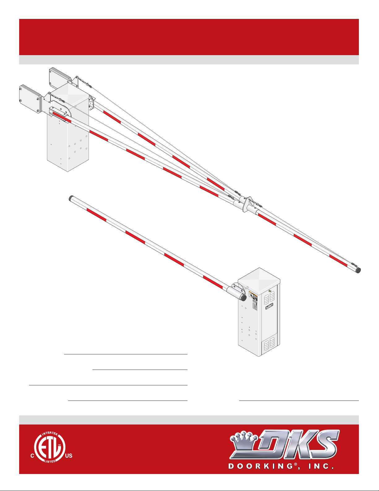
Installation/Owner’s Manual
1601 / 1602
1601 / 1602
1601 / 1602
Barrier Gate Operator
Use this manual for circuit board 1601-010 Revision V or higher.
1602
1601-065-G-6-12
Date Installed:
Installer/Company Name:
Phone Number:
Leave Manual with Owner
UL 325 Compliant
Circuit Board
Serial Number
and Revision Letter:
Copyright 2012 DoorKing, Inc. All rights reserved.
CO
N
F
O
AN
R
M
S
I
S
/
U
T
L
O
-
3
C
C
2
AN
E
5
R
/
T
C
I
F
SA
IE
D
C
V
2
T
2.
E
O
H
2
I
N
C
O
U
5
3
.
CL
3
L
8
2
2
A
ASS
4
R
7
G
AT
E
M
O
O
D
P
E
E
L
R
A
T
S
O
E
H
R
R
P
I
AL
V
O
L
T
S
AMPS
MAX
PH
G
ASE
A
T
E
L
O
Do
A
60
D
o
H
r
K
z
in
g
,
In
c
.
,
I
n
g
l
e
w
o
o
d
,
C
A
1601
Copyright 2009 DoorKing, Inc. All rights reserved.
TM
Page 2

Page 3

TABLE OF CONTENTS
SPECIFICATIONS 2-3
UL325 Entrapment Protection
Safety Information for Vertical Barrier Arm
SECTION 1 - INSTALLATION 6
1.1 Underground Conduit Requirements
1.2 New Concrete Pad
1.3 Trenching Existing Concrete
SECTION 2 - WIRING 8
2.1 High Voltage Wire Runs
2.2 High Voltage Terminal Connections
2.3 Dual Gate Operators (Primary/Secondary)
2.4 Main Terminal Description
2.5 Control Wiring
2.6 P.A.M.S. Multiple Gate Operator Sequencing
10
11
12
4
5
6
7
7
8
8
9
SECTION 3 - LOOP DETECTOR LANE SETUPS
3.1 Entry Lane Only
3.2 Exit Lane Only
3.3 2-Way Traffic Lane
3.4 Ticket Spitter Entry Lane
3.5 Operator Timer ON Entry Lane (No Down Loop)
13
13
14
15
16
SECTION 4 - ARM INSTALLATION 18
4.1 Mounting Hub(s)
4.2 Mounting Arm(s)
4.3 1602 3-Piece Arm Assemblies
18
19
19
SECTION 5 - ADJUSTMENTS 20
5.1 1601 Circuit Board Description and Adjustments
5.2 DIP-Switch SW 1 and SW 2 Settings
5.3 Reverse Arm UP and DOWN Positions
5.4 Magnetic Limit Adjustment
5.5 Reverse Sensor Adjustment
5.6 Manual Operation of the Arm
20
21-23
24
25
25
26
SECTION 6 - OPTIONAL CONVENIENCE OPEN SYSTEM 27
6.1 Operating Mode
6.2 DC System Description
6.3 DIP-Switch Settings
27
28
28
17
SECTION 7 - OPTIONAL ACCESSORIES INSTALLATION 29
7.1 Contact Sensor (Reversing Edge)
7.2 Fan Kit
7.3 Heater Kit
SECTION 8 - TECHNICAL INSTRUCTIONS 32
8.1 Maintenance Schedule
8.2 Diagnostics Check
8.3 Troubleshooting
8.4 Accessories Parts List
Wiring Schematics
1601-065-G-6-12
29
30
31
32
33
33-34
35
36-39
1
Page 4
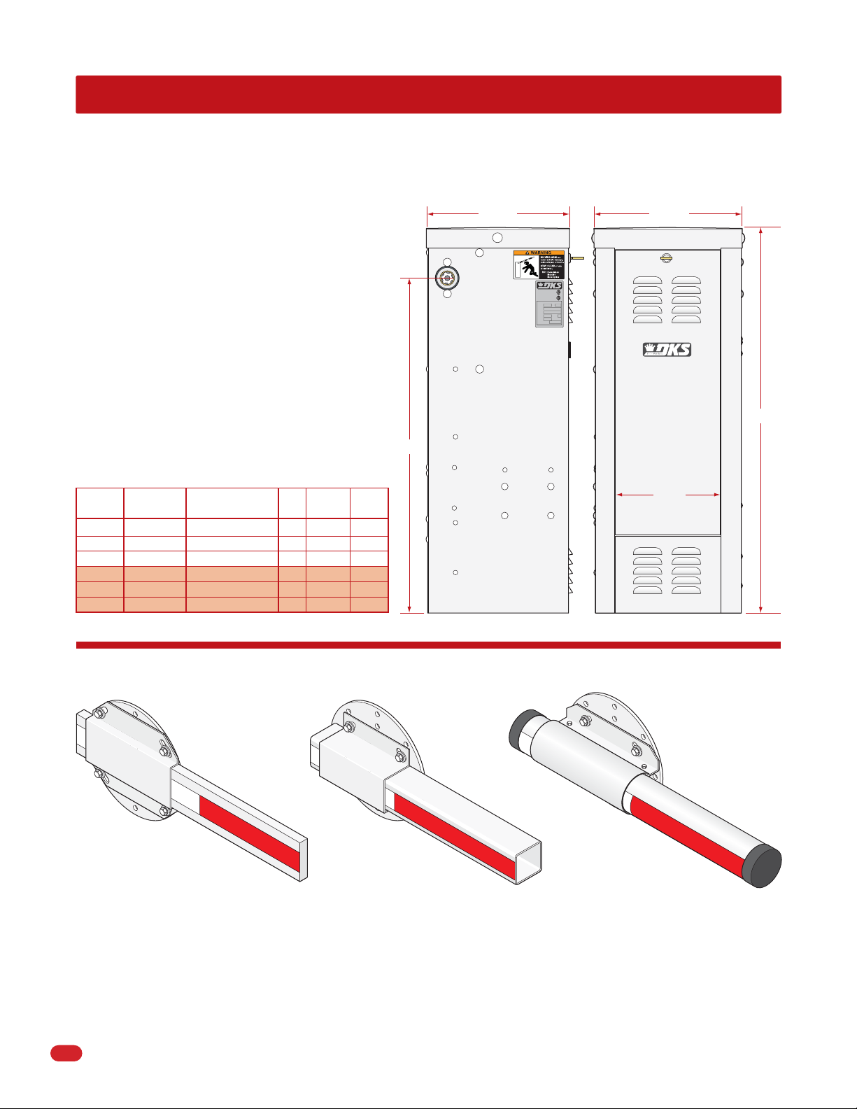
1601 SPECIFICATIONS
Use this manual for the Model 1601 operators with circuit board 1601-010 Rev V or higher ONLY.
Class of Operation
Model 1601 - UL 325 Class II, III, IV – ETL Listed
Type of Gate
Single Traffic Lane Vehicular Barrier Gate Only
Arm Types
Wood/Plastic/Aluminum – Straight or Folding Arm
Gate Cycles
High Cycle
Primary Entrapment Protection
Inherent entrapment sensing system (Type A)
Secondary Entrapment Protection
Provision for connection of a non-contact sensor
(Type B1) and/or contact sensor (Type B2)
34.5”
1601 Housing
14.74”
CONFORMS TO
ANSI/UL-325
53382
CERTIFIED TO
CAN/CSA C22.2 NO. 247
VEHICULAR GATE OPERATOR
CLASS
HP
MODEL
SERIAL
VOLTS PHASE
AMPS 60 Hz
MAX GATE LOAD
DoorKing, Inc., Inglewood, CA
15.26”
39.6”
Model #
1601-080
1601-087
1601-089
1601-081
1601-088
1601-090
Drawings not to scale
Convenience
Open
No
No
No
Yes
Yes
Yes
Horsepower - Volts
1/2 HP - 115 VAC
1/2 HP - 230 VAC
1/2 HP - 460 VAC
1/2 HP - 115 VAC
1/2 HP - 230 VAC
1/2 HP - 460 VAC
14 Ft. Wood Arm Only P/N 1601-348
Wood Arm Mounting Kit P/N 1601-240
Wood Folding Arm Kit P/N 1601-384
Foam Padding for 14 Ft. Arm P/N 1601-260
Amp
5.7
2.9
1.5
5.7
2.9
1.5
Max Arm
Length
14 Ft.
14 Ft.
14 Ft.
14 Ft.
14 Ft.
14 Ft.
Speed
90°
1.5 Sec
1.5 Sec
1.5 Sec
1.5 Sec
1.5 Sec
1.5 Sec
1601 Barrier Arm Kit Options
Folding arm assemblies can be installed for low headroom applications.
12 Ft. Plastic Arm Only P/N 1601-571
Plastic Arm Mounting Kit P/N 1601-241
Plastic Folding Arm Kit P/N 1601-383
Aluminum Arm Mounting Kit P/N 1601-242
Foam Padding for 14 Ft. Arm P/N 1601-260
10.8”
14 Ft. Aluminum Arm Only P/N 1601-516
Aluminum Folding Arm Kit P/N 1601-610
DoorKing, Inc. reserves the right to make changes in the products described in this manual without notice and without obligation of DoorKing, Inc. to notify any persons
of any such revisions or changes. Additionally, DoorKing, Inc. makes no representations or warranties with respect to this manual. This manual is copyrighted, all rights
reserved. No portion of this manual may be copied, reproduced, translated, or reduced to any electronic medium without prior written consent from DoorKing, Inc.
2
1601-065-G-6-12
Page 5
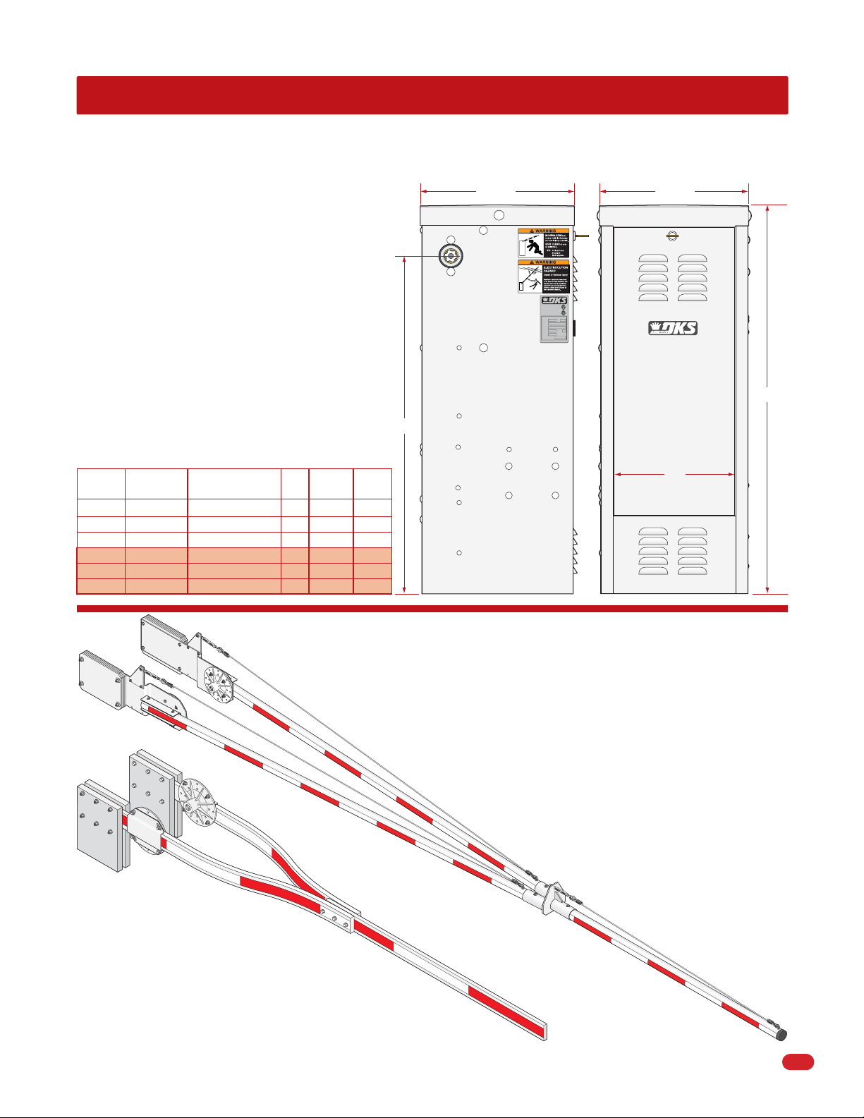
1602 SPECIFICATIONS
Use this manual for the Model 1602 operators with circuit board 1601-010 Rev V or higher ONLY.
Class of Operation
Model 1602 - UL 325 Class III, IV – ETL Listed
Type of Gate
Wide Traffic Lane Vehicular Barrier Gate Only
Arm Types
Wood/Aluminum 3-piece counter-balanced assembly
Gate Cycles
Low Cycle
Primary Entrapment Protection
Inherent entrapment sensing system (Type A)
Secondary Entrapment Protection
Provision for connection of a non-contact sensor
(Type B1) and/or contact sensor (Type B2)
34.5”
1602 Housing
15.74”
CONFORMS TO
ANSI/UL-325
53382
CERTIFIED TO
CAN/CSA C22.2 NO. 247
VEHICULAR GATE OPERATOR
CLASS
HP
MODEL
SERIAL
VOLTS PHASE
AMPS 60 Hz
MAX GATE LOAD
DoorKing, Inc., Inglewood, CA
15.26”
39.6”
Model #
1602-080
1602-082
1602-084
1602-081
1602-083
1602-085
Drawings not to scale
Convenience
Open
No
No
No
Yes
Yes
Yes
Horsepower - Volts
1 HP - 115 VAC
1 HP - 230 VAC
1 HP - 460 VAC
1 HP - 115 VAC
1 HP - 230 VAC
1 HP - 460 VAC
Amp
9.7
4.9
2.5
9.7
4.9
2.5
Max Arm
Length
28 Ft.
28 Ft.
28 Ft.
28 Ft.
28 Ft.
28 Ft.
Speed
90°
5.5 Sec
5.5 Sec
5.5 Sec
5.5 Sec
5.5 Sec
5.5 Sec
13”
1602 Barrier Arm Kit Options
3-Piece 20 Ft. Aluminum Arm Kit P/N 1602-162
3-Piece 24 Ft. Aluminum Arm Kit P/N 1602-164
3-Piece 27 Ft. Aluminum Arm Kit P/N 1602-166
(All hardware included in kits)
Foam Padding for 14 Ft. Arm P/N 1601-260
1601-065-G-6-12
3-Piece 20 Ft. Wood Arms Only P/N 1602-340
3-Piece 20 Ft. Wood Arms Mounting Kit P/N 1602-041
Foam Padding for 14 Ft. Arm P/N 1601-260
3
Page 6

UL 325 Entrapment Protection
Class I
A vehicular gate operator (or system) intended for use in a
home of one-to four single family dwelling, or a garage or
parking area associated therewith.
Class II
A vehicular gate operator (or system) intended for use in a
commercial location or building such as a multi-family
housing unit (five or more single family units) hotel,
garages, retail store or other building servicing the general
public.
STATE PRISON
Class III
A vehicular gate operator (or system) intended for use in a
industrial location or building such as a factory or loading
dock area or other locations not intended to service the
general public.
Class IV
A vehicular gate operator (or system) intended for use in a
guarded industrial location or building such as an airport
security area or other restricted access locations not
servicing the general public, in which unauthorized access
is prevented via supervision by security personnel.
This table illustrates the entrapment protection requirements for each of the four UL 325 classes.
UL 325
Classifications
Class I and II
Class III
Class IV
A - Inherent entrapment protection system.
B1 - Provision for connection of, or supplied with, a non-contact sensor (photoelectric sensor or the equivalent).
When used as the PRIMARY device, must be monitored.
B2 - Provision for connection of, or supplied with, a contact sensor (edge device or the equivalent).
When used as the PRIMARY device, must be monitored.
C - Inherent adjustable clutch or pressure relief device.
D - Provision for connection of, or supplied with, an actuating device requiring continuous pressure to maintain
opening or closing motion of the gate.
E - An inherent audio alarm.
Horizontal Slide, Vertical Lift, Vertical Pivot Swing and Vertical Barrier (arm)
Primary Protection
A B1, B2 or D A, B1, B2, C or DA or C
A, B1 or B2 A, B1, B2, D or E A, B1, B2, C or DA, B1, B2 or C
A, B1, B2 or D A, B1, B2, D or E A, B1, B2, C, D or EA, B1, B2, C or D
Secondary Protection Primary Protection Secondary Protection
4
1601-065-G-6-12
Page 7
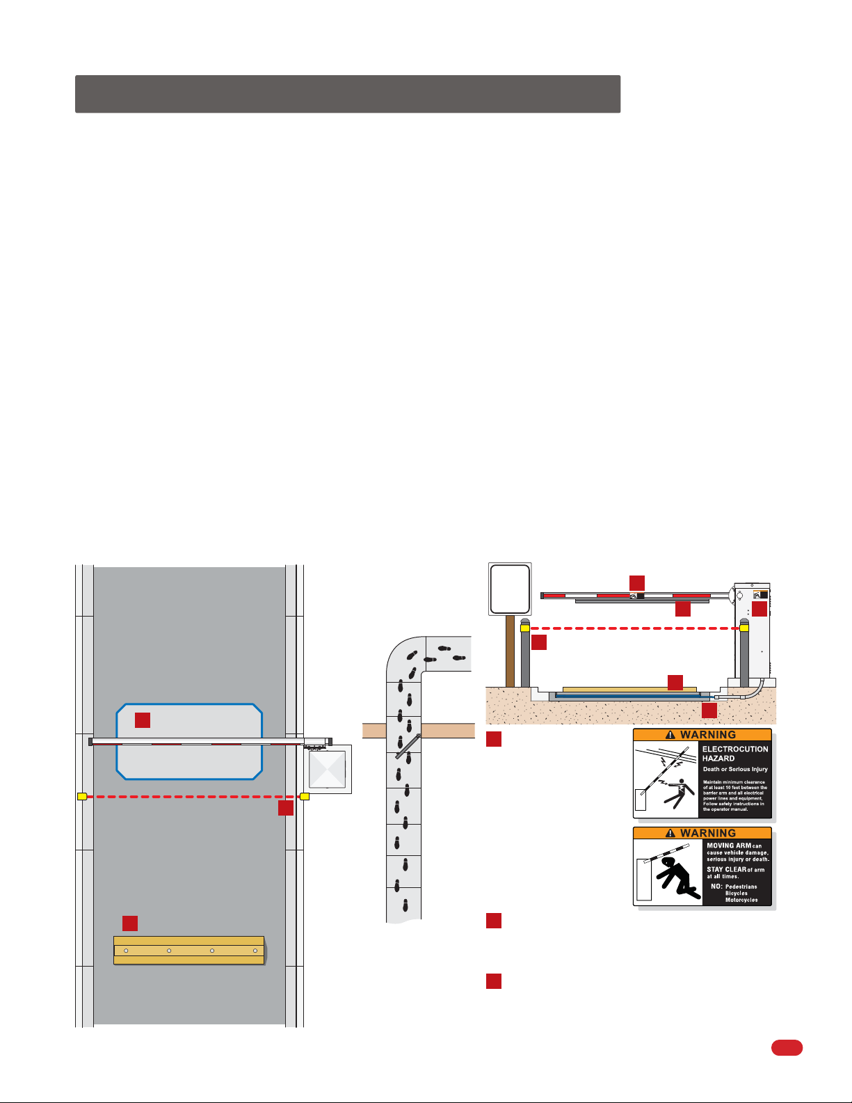
Safety Information for Vertical Barrier Arm
Reduce the risk of injury or death, read and follow all instructions.
Familiarize yourself with safety warnings, instructions, illustrations, and wiring guidelines to ensure that the installation is performed in a safe
and professional manner. Prior to installation check all local building codes and ordinances to ensure compliance
• Do not install the operator in such a way that the arm moves within 2 feet of a rigid object or 10 feet from high voltage power wires
with arm in the raised position.
• Speed limit through barrier area is 5 MPH. Install speed bumps and warning signs where visible in the area of the barrier gate, failure to
do so may result in injury, damage to operator and vehicle.
• Users should be familiar with proper use of operator, these include; hardware operation, reversing functions and testing, reversing loops,
inherent reversing system, electric edges, photoelectric cells related external devices and possible hazards.
• Keep adults, children and objects away from operator and HAZARD ZONES. Pedestrians must be provided with a separate access.
• All electrical connections should be made in accordance with local electrical codes.
• Security features should be installed to avoid unauthorized use.
• Controls must be installed away from the operator to avoid any contact when operating the controls. If the installed
hardware is in violation of these restrictions remove the operator from service immediately and contact your service dealer.
• When manually operating the gate operator arm, the user MUST make sure that the gate area is clear BEFORE operating the controls.
• When removing the operator lift the arm to the full open position and shut off power at the service panel.
• Operators and components should be properly installed and maintained following the recommended service schedule, test the operator
monthly. Keep all debris away from operator housing vents and off of arm. Contact your service dealer for any maintenance or repairs.
• Vehicular operators can produce high levels of force, it is important that you are aware and eliminate possible HAZARDS; Pinch Points,
Entrapment Areas, Overhead Power Wires, Absence of Controlled Pedestrian Access, Traffic Backup.
SPEED
LIMIT
5
D
C
Warning Signs
C
WARNING
MOVING ARM
can
cause vehicle damage,
serious injury or death.
STAY CLEAR
of arm
at all times.
NO:
Pedestrians
Bicycles
Motorcycles
E
C
B
A
Minimizes the potential of the
arm closing when a vehicle is
present. Number and
placement of loop(s) is
dependent on the application.
A
Down Loop
Speed Limit Sign
Permanently mounted
and easily visible.
D
D
B
Speed Bump
Helps increase distance
and time between vehicles.
Separate
Pedestrian
Walkway
Located so pedestrians
cannot come in contact
with the barrier arm.
Non-Contact Sensor
Minimizes the potential of the arm lowering on
vehicular or other traffic that loops cannot sense.
E
Contact Sensor
Minimizes the potential of the arm lowering on
vehicular or other traffic that loops cannot sense.
WARNING
MOVING ARM
can
cause vehicle damage,
serious injury or death.
STAY CLEAR
of arm
at all times.
NO:
Pedestrians
Bicycles
Motorcycles
1601-065-G-6-12
5
Page 8
SECTION 1 - INSTALLATION
Prior to beginning the installation of the barrier gate operator, we suggest that you become familiar with the
instructions, illustrations, and wiring guide-lines in this manual. This will help insure that your installation is
performed in an efficient and professional manner.
The proper installation of the vehicular barrier gate operator is an extremely important and integral part of the
overall access control system. Check all local building ordinances and building codes prior to installing this
operator. Be sure your installation is in compliance with local codes.
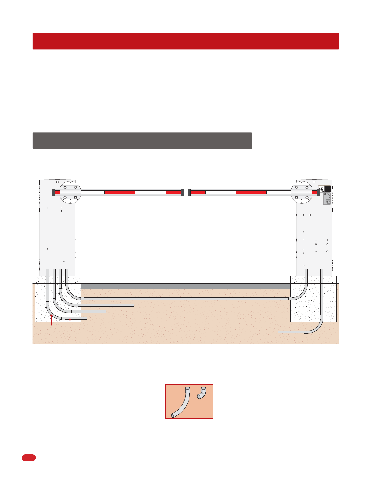
1.1 Underground Conduit Requirements
Primary
Operator
Access Door
Concrete Pad
Sweeps
Primary/Secondary Interconnection Cable (Dual Operator Application Only)
AC Input Power (High Voltage wire insulation)
3/4 Inch Minimum
The operator(s) should be installed with the access
door of the operator opposite the traffic lane.
Note: If your installation has the access door(s) facing the traffic
lane, see Section 5.3 (Page 24) to reverse the factory setup.
Traffic Lane
Control and/or P.A.M.S. Wires (Low Voltage wire insulation)
Loop Lead-In Wires (Low Voltage wire insulation)
AC Input Power (High Voltage wire insulation)
Secondary
Operator
WARNING
MOVING ARM
cause vehicle damage,
serious injury or death.
STAY CLEAR
at all times.
NO:
CONFORMS TO
ANSI/UL-325
CERTIFIED TO
CAN/CSA C22.2 NO. 247
VEHICULAR GATE OPERATOR
CLASS
MODEL
SERIAL
VOLTS PHASE
AMPS 60 Hz
MAX GATE LOAD
DoorKing, Inc., Inglewood, CA
can
of arm
Pedestrians
Bicycles
Motorcycles
53382
HP
Access Door
Concrete Pad
• The conduit requirements are for a typical slide gate operator installation (the secondary operator is shown for
those applications where a secondary operator may be used). The conduit requirements for your application may
vary from this depending on your specific needs.
• Use only sweeps for conduit bends. Do not use 90° elbows as this will make wire pulls very difficult and can cause
damage to wire insulation.
• DoorKing recommends using 3/4-inch conduit.
Sweep
YES
Elbow
NO
• Be sure that all conduits are installed in accordance with local codes.
• Never run low voltage rated wire insulation in the same conduit as high voltage rated wire insulation.
6
1601-065-G-6-12
Page 9
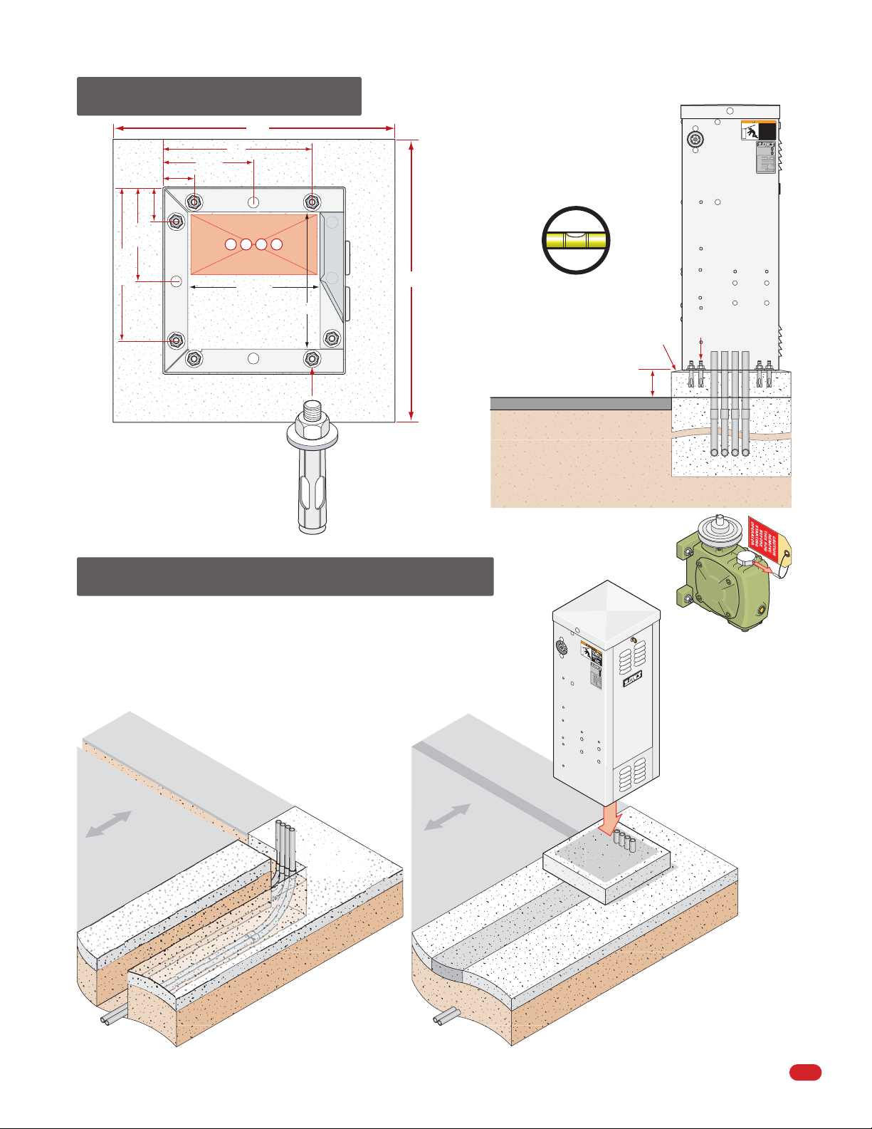
1.2 New Concrete Pad
23”
12”
7.25”
2.5”
7.5”
2.625”
12.375”
Approximate position
of conduit runs.
10.75”
Inside
Operator
Mounting Flange
Concrete Pad
Secure the mounting
flange to concrete
with 1/2” x 3”
sleeve anchors
(not supplied).
11”
1/2
Mount
operator
centered
on pad.
Access Door
23”
The operator(s) should be
installed with the access
door of the operator
opposite the traffic lane.
Concrete pad MUST be level.
Note: Bevel the edges of concrete
pad to eliminate water puddling
under the operator.
Traffic Lane
4” minimum
underground depth of the
concrete pad is determined by
soil conditions and local
building codes.
Reinforced concrete recommended.
Sleeve
Anchors
Conduit
WARNING
MOVING ARM
cause vehicle damage,
serious injury or death.
STAY CLEAR
at all times.
CONFORMS TO
ANSI/UL-325
CERTIFIED TO
CAN/CSA C22.2 NO. 247
VEHICULAR GATE OPERATOR
CLASS
MODEL
SERIAL
VOLTS PHASE
AMPS 60 Hz
MAX GATE LOAD
DoorKing, Inc., Inglewood, CA
can
of arm
NO:
Pedestrians
Bicycles
Motorcycles
53382
HP
Access Door
1.3 Trenching Existing Concrete
Trench path(s) in the existing concrete wide enough for all the conduit runs.
After the conduit has been run, fill the trench with soil to bottom of existing
concrete and tamp down. Pour new concrete with a 4 inch pad height
minimum (Reinforce concrete if possible). Secure the mounting flange to
concrete with 1/2” x 3” sleeve anchors (not supplied). See illustration above
for mounting operator.
Traffic Lane
The operator(s) should be
installed with the access
door of the operator
opposite the traffic lane.
Traffic Lane
C
O
N
F
O
A
R
N
M
S
I
S
/
U
T
L
O
-3
C
C
2
A
E
5
N
R
/
T
C
I
F
S
I
A
E
D
C
VE
2
T
2
O
.
H
2
ICU
N
O
.
C
LA
2
L
4
A
7
R
S
S
G
A
TE
M
O
O
D
PE
E
L
R
A
T
S
E
H
R
P
I
A
L
V
O
L
T
S
A
M
P
S
M
A
P
X
H
G
A
A
S
T
E
E
L
O
A
D
6
D
o
0
o
H
r
K
z
i
n
g
,
I
n
c
.
,
I
n
g
l
e
w
o
o
d
,
C
4” height min.
5
3
3
8
2
O
R
A
Access
Door
Remove breather
pin from gear
reducer AFTER the
operator has been
secured in place.
1601-065-G-6-12
7
Page 10
SECTION 2 - WIRING
Before attempting to connect any wiring to the operator, be sure that the circuit breaker in the electrical panel is in the OFF
position. Permanent wiring must be installed to the operator as required by local electrical codes. It is recommended that a
licensed electrical contractor perform this work.
Since building codes vary from city to city, we highly recommend that you check with your local building department prior
to installing any permanent wiring to be sure that all wiring to the operator (both high and low voltage) complies with local
code requirements.
THIS GATE OPERATOR MUST BE PROPERLY GROUNDED!!
2.1 High Voltage Wire Runs
The distance shown in the chart is measured in “Feet” from the operator to the power source. If power wiring is greater than
the maximum distance shown, it is recommended that a service feeder be installed. When large gauge wire is used, a separate
junction box must be installed for the operator connection. The wire table is based on stranded copper wire. Wire run calculations are based on the NEC recommended maximum 3% voltage drop on the power line, plus an additional 10% reduction in
distance to allow for other losses in the system.
This table illustrates the high voltage wire size and distance requirements.
Model
Type
1601 - 1/2 HP
1601 - 1/2 HP
1601 - 1/2 HP
1602 - 1 HP
1602 - 1 HP
1602 - 1 HP
“Optional” 3.3 Amp Heater Installation Note: When installing the heater, refer to the “high voltage AC power wire size and
distance requirements” table on the instruction sheet with the heater kit (P/N 1601-092) for AC power wire run requirements.
Voltage
Required
115 5.7 170 275 460 690
230
460 1.5 2,585 4,140 6900 10,350
115 9.7 100 162 270 405
230 4.9 395 630 1,055 1,580
460 2.5 1,550 2,480 4,140 6,210
Never run low voltage rated wire insulation in the same conduit as high voltage rated wire insulation.
Amps
Required
2.9 665 1,070 1,780 2675
12 AWG 10 AWG 8 AWG 6 AWG
Wire Size / Distance in Feet
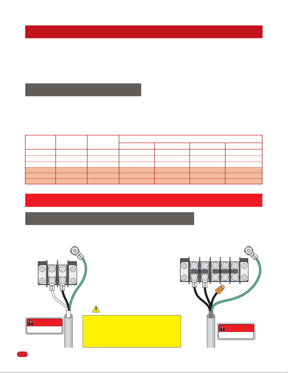
2.2 High Voltage Terminal Connections
115 VAC Models
Chassis
Ground
Neutral
115 VAC
• Route incoming high voltage power in
it’s OWN conduit.
• Be sure wiring is installed in accordance
with local codes. Be sure to color code all
wiring.
• It is recommended that a surge suppressor
be installed on the high voltage power lines
to help protect the operator and circuit
board from surges and power fluctuations.
230 VAC/460 VAC Models
Chassis
Ground
230/460 VAC
230/460 VAC
115 VAC Neu
115 VAC Neu
115 VAC Hot
Input
Output
8
DANGER
HIGH VOLTAGE!
High Voltage
Conduit
• Dual operators (Primary/Secondary)
require AC power to each operator.
Keep wire clear of all moving parts.
DO NOT power up and cycle the operator until
the “DIP-Switches” have been set for the 1601
OR 1602 model (See pages 20 and 21).
The operator will not function properly unless the
switches have been correctly set.
230 and 460 Volt 3-phase
input, use only two legs of
the incoming 3-phase power.
DANGER
HIGH VOLTAGE!
High Voltage
Conduit
1601-065-G-6-12
Page 11
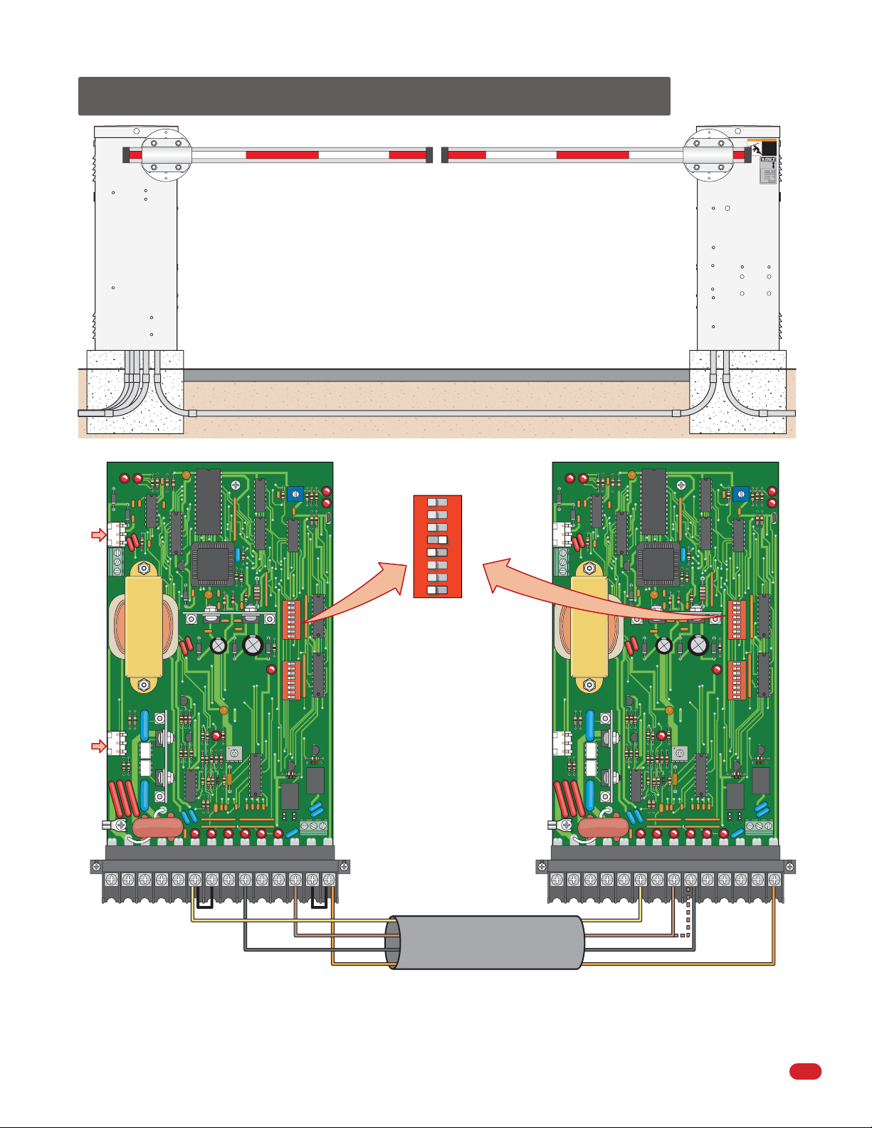
2.3 Dual Gate Operators (Primary/Secondary)
WARNING
MOVING ARM
cause vehicle damage,
serious injury or death.
STAY CLEAR
at all times.
NO:
CONFORMS TO
ANSI/UL-325
CERTIFIED TO
CAN/CSA C22.2 NO. 247
VEHICULAR GATE OPERATOR
CLASS
MODEL
SERIAL
VOLTS PHASE
AMPS 60 Hz
MAX GATE LOAD
DoorKing, Inc., Inglewood, CA
can
of arm
Pedestrians
Bicycles
Motorcycles
53382
HP
Primary
Operator
Access
Control
Device,
Loops
AC Power
Primary Circuit Board
UP
LOOP
UP Loop DetectorDOWN Loop Detector
1601
Primary/Secondary Interconnection Cable Conduit
Secondary Circuit Board
Settings using
Down Loop
ON
1
2 3 4 5 6 7 8
SW 1
SW 1, switch 4 is ON.
SW 1, switch 5 is OFF.
SW 1, switch 8 is OFF.
Set other DIP-switches
based on gate operation
preferences (See page 21).
UP
LOOP
POWER
2 3 4 5 6 7 8
1
2 3 4 5 6 7 81
TIME
DELAY
ON
ON
1601
Secondary
Operator
AC Power
TIME
DELAY
ON
2 3 4 5 6 7 8
ON
1
2 3 4 5 6 7 81
POWER
Set both operators DIP-switches
DOWN
LOOP
REVERSE
SENSITIVITY
(SW 1 and SW 2) to the same
settings.
DOWN
LOOP
REVERSE
SENSITIVITY
Each operator requires AC power.
Connect loop detectors and
NC NO
access control devices to the
NC NO
PRIMARY operator ONLY.
12345678 9 10 11 12 13 14
Jumper Wire Jumper
Yellow
Brown
Gray
Orange
Primary/Secondary
Interconnection Cable
Sold separately from DoorKing.
4 wires used (8 - 18 AWG wires total).
123456 7 8910 11 12 13 14
Yellow
Brown
Reverse loops
Gray
When using Reverse Loops:
DIP-Switch settings: SW 1, switch 4 is OFF. SW 1, switch 5 is OFF. SW 1, switch 8 is OFF. Set other DIP-switches based on gate operation preferences.
Interconnection cable: The BROWN wire must be connected to SECONDARY TERMINAL #9 along with the GRAY wire. All other terminal wire connections are
the same as shown above.
1601-065-G-6-12
Orange
9
Page 12
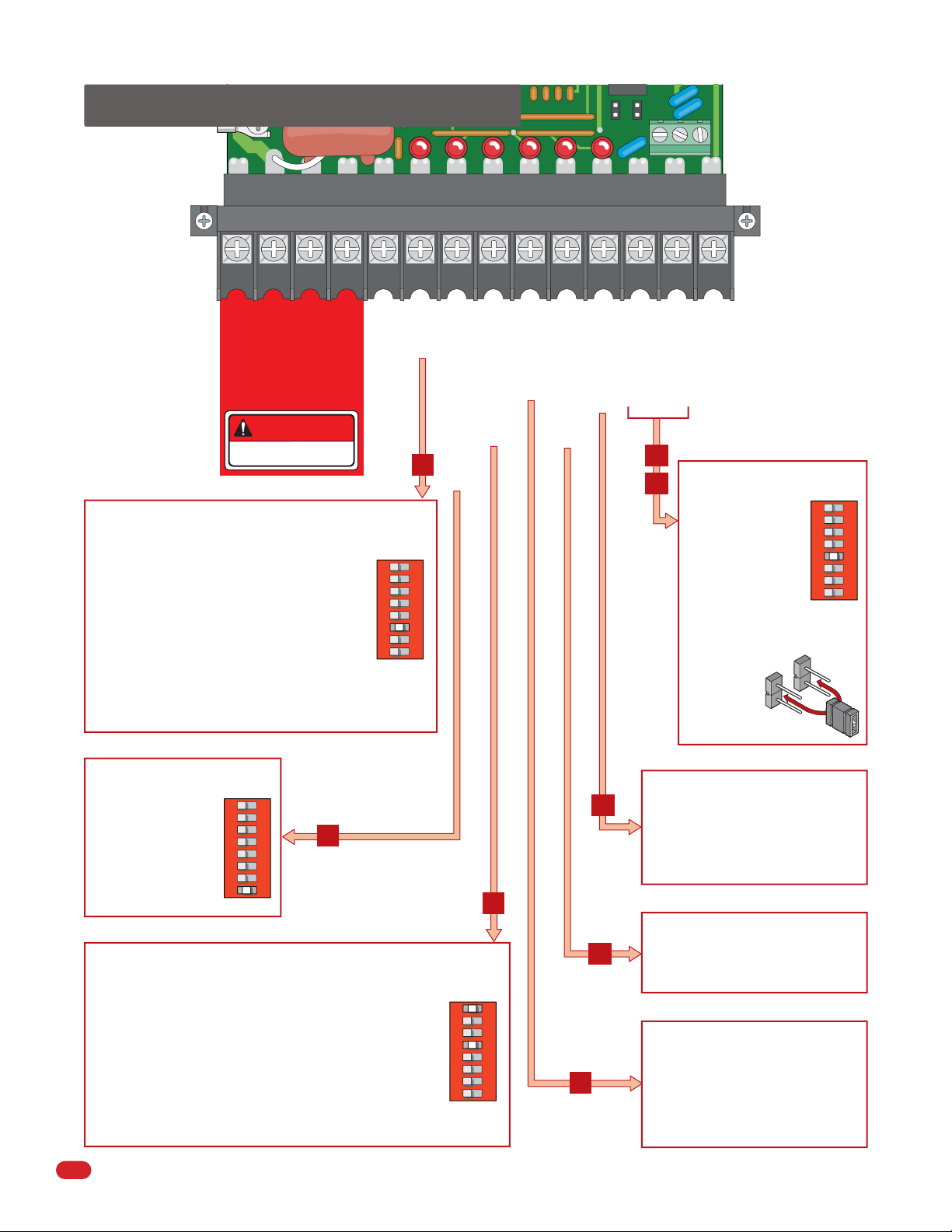
2.4 Main Terminal Description
1234567891011121314
DOWN/REVERSE Input
UP INPUT or UP LOOP Output
UP Input
24 VAC - 250 mamp. max.
115 VAC Motor
115 VAC Motor
115 VAC Power
115 VAC Neutral
DANGER
HIGH VOLTAGE!
Function is dependent on the setting of programming SW 1, switch 6.
When switch 6 is OFF, this input will cause the
operator to rotate the arm to the up position. If the arm
is in the down cycle, this input will reverse the arm to
the up position. If this terminal has a constant input,
the arm will remain in the up position regardless of any
down input or timer command to rotate down.
When switch 6 is ON, this input will cause the operator
to rotate the arm to the up position when it is down,
and will cause the operator to rotate the arm to the
down position when it is up. If the auto timer is turned
ON (Not recommended if switch 6 is ON), this input
will override the timer and rotate the arm to the down
position. If the arm is in the down cycle, this input will
reverse the arm to the up position.
1
2 3 4 5 6 7 8
6
ON
SW 1
ENABLE UP Input
MOMENTARY UP Input
REVERSE Input
NC NO
Dry Relay Contact
12
13
Low Voltage Common
Dry Relay Contact
Function is dependent on the setting
of programming SW 1, switch 5.
When switch 5 is OFF,
activation of the down
loop will activate the
relay.
When switch 5 is ON,
activation of the UP loop
will activate the relay.
Relay contacts can be set
for Normally Open (NO)
or Normally
Closed (NC)
operation.
Contact rating
is 1 amp
maximum at 24 Volts.
NC
NO
1
2 3 4 5 6 7 8
SW 1
ON
Function is dependent on the setting
of programming SW 1, switch 8.
When switch 8 is ON, the
function of this input is
identical to terminal 6.
When switch 8 is OFF,
this terminal becomes
the logic output of the up
loop detector.
Function is dependent on the setting of programming SW 1, switches 1 and 4.
With switch 1 OFF and switch 4 ON, activation and then deactivation of
this input will rotate the arm to the down position, provided that the
deactivation of the input happens while the arm is in the full up
position. This input will override the auto timer if it is turned ON. If the
arm is in the down position, traveling in the down cycle, or traveling in
the up cycle, activation and deactivation of this input has no effect on
the arm.
With switches 1 and 4 are ON, activation and then deactivation of this
input will rotate the arm to the down position after it reaches the full
up position regardless of when the deactivation of the input occurred.
When switch 4 is OFF, this input is identical to the reverse input,
terminal 9.
10
1
2 3 4 5 6 7 8
ON
7
SW 1
1
2 3 4 5 6 7 8
SW 1
ON
This input is used when sequencing the
11
1601 with a slide or swing gate operator in
PAMS applications. This input is only active
after a MOMENTARY UP input is received.
Activation of this input will rotate the arm
to the up position or reverse an arm in the
down cycle to the up position.
8
This input is used when sequencing the
1601 with a slide or swing gate operator in
10
9
PAMS applications. Activation of this input
will rotate the arm to the up position one
time, and activates the enable up input.
When the arm is in the down position,
activation of this input has no effect.
When the arm is in the up position,
activation of this input will prevent the arm
from rotating to the down position. If the
arm is in the down cycle, activation of this
input will reverse the arm to the up
position.
1601-065-G-6-12
Page 13
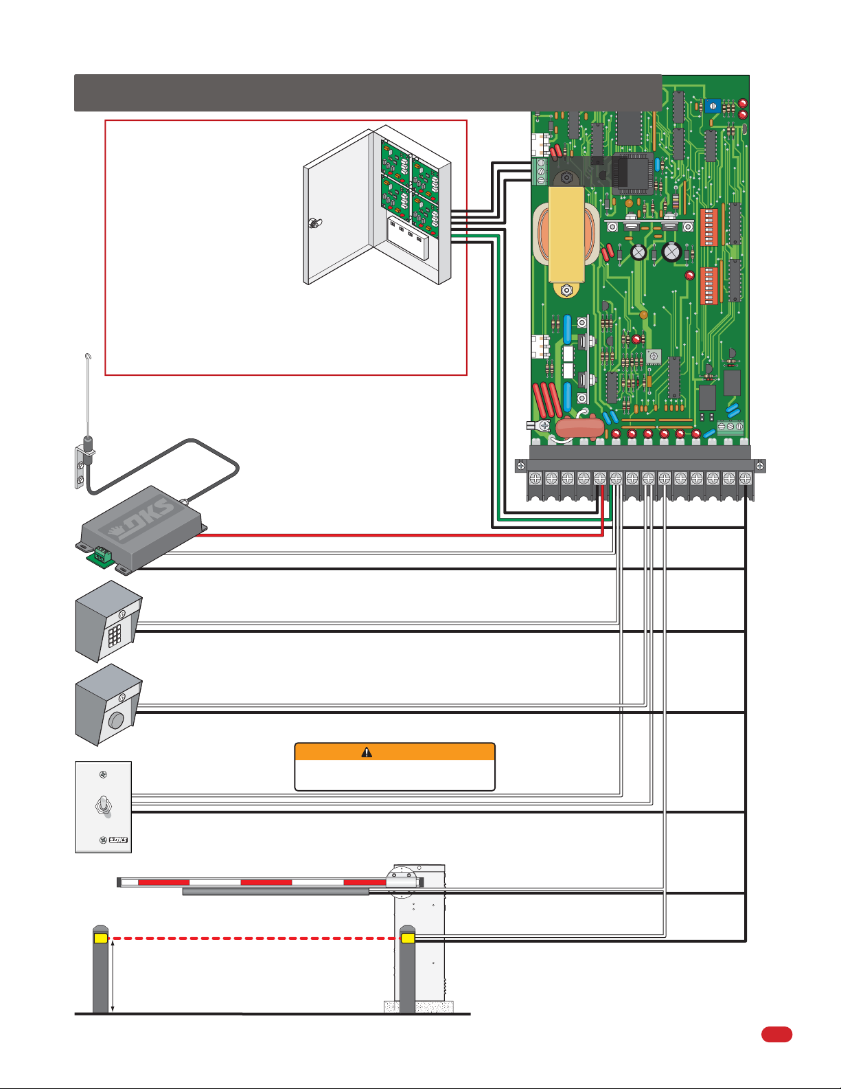
2.5 Control Wiring for Single/Primary Operator
UP
DoorKing Access Control System
(Model 1833, 1835, 1837 or 1838)
tracker system can be connected.
This system can keep track of gate
operator cycle count, shorted inputs,
loop detector problems, any forced
entry attempts, if the gate has struck
anything during the open or close
cycle, power interruptions, etc.
For more detailed information refer
to the Tracker Installation and Wiring
Manual, DoorKing P/N 2351-010.
Antenna mounted outside
operator housing.
Coax Antenna Kit
P/N 1514-073
Gate Tracker
(Quad Box Shown)
Terminal 6 required only if the
tracker board will activate the
gate operator. Refer to the
manual 2351-065 for detailed
information.
LOOP
Gate Operator
Data Terminal
1601
DOWN
LOOP
1234567 8910 11 12 13 14
REVERSE
SENSITIVITY
POWER
TIME
DELAY
2 3 4 5 6 7 8
1
2 3 4 5 6 7 8 1
NC NO
ON
ON
HOLD OPEN
OPEN
3-Wire Radio Receiver
3. 24 Volt
2. Relay
1. Com
Up-Inputs
Down-Inputs
WARNING
Manual Gate Control Toggle
P/N 1200-017
Up toggle position: User toggles switch up to hold gate open.
Center toggle position: Is neutral for normal operation.
Down toggle position: User momentarily toggles switch down to open gate.
User MUST make sure gate area IS CLEAR
before manually operating gate arm.
Contact Sensor (Reversing Edge)
See page 29
Com
1601-065-G-6-12
Non-Contact Sensor (Photo Sensors)
21” Typical Beam Height.
27.5” Max. Beam Height.
Contact and Non-Contact Sensors Note:
Helps minimizes the potential of the arm
lowering on vehicular or other traffic that
loops cannot sense.
11
Page 14

2.6 P.A.M.S. Multiple Gate Operator Sequencing
Perimeter Access Management Solution (PAMS) application allows open and close cycle sequencing of a DoorKing barrier gate
operator and a DoorKing slide or swing gate operator. For detailed PAMS wiring information, refer to the PAMS Technical
Information and Wiring Manual.
Operators are wired to each
other to sequence their
open and close cycles.
Operators are wired to each
other to sequence their
open and close cycles.
BARRIER and SLIDE
BARRIER and SWING
12
1601-065-G-6-12
Page 15

SECTION 3 - LOOP DETECTOR LANE SETUPS
Before attempting to connect any wiring to the operator, be sure that the circuit breaker in the electrical panel is in the OFF
position. Permanent wiring must be installed to the operator as required by local electrical codes. It is recommended that a
licensed electrical contractor perform this work.
Loop detector wiring shown is for DoorKing model 9409 Dual Channel and 9410 Single Channel plug-In loop detectors only.
If using other loop detectors refer to the separate Loop Information Manual for installation instructions, loops/preformed
loops and wiring diagrams. All inputs to the main terminal are NORMALLY OPEN.
3.1 Entry Lane Only
TIME
A
POWER
2 3 4 5 6 7 8
1
2 3 4 5 6 7 8 1
DELAY
ON
SW 1
ON
SW 2
A
1
2 3 4 5 6 7 8
SW 1
NO
Com
ON
SW 1, switch 4 is ON.
SW 1, switch 7 is
OFF (Timer). The arm
will rotate down after
the vehicle clears the
down loop. See timer
note below.
UP
LOOP
1601
REVERSE
DOWN
LOOP
SENSITIVITY
NC NO
9409
Dual Channel
123456 7891011121314
If the arming loop is not used, then a single channel loop
detector can be used (9410) in the down loop port. Connect the
down loop to loop 1 on this detector. Connect the access control
device directly to main terminal 6 and 14.
Arming Loop Note: The arming loop only allows the access control
device to function when a vehicle is on the loop, otherwise it will not
function. This prevents pedestrians from gaining access through the
vehicular gate.
Timer Note: The timer can be used with a down loop. When timer is ON
with a down loop, it will start countdown when the arm has fully raised.
Activation of the down loop will cancel timer countdown. Useful when
an access control device has been activated but vehicle does not move
forward to activate the down loop. The arm will remain UP. Timer will
time out and lower the arm without the down loop being activated.
Main Terminal
NO
Com
Access
Control
Device
Down Loop
12 Ft.
Arming Loop
for Access
Control Device
(Optional)
Speed Bump
Helps increase distance
and time between vehicles.
1601-065-G-6-12
13
Page 16

3.2 Exit Lane Only
1
2 3 4 5 6 7 8
A
Single Channel
UP
LOOP
9410
DOWN
LOOP
ON
SW 1, switch 4 is ON.
SW 1, switch 7 is OFF (Timer). The arm will rotate
down after the vehicle clears the down loop.
See note below.
SW 1
TIME
DELAY
ON
2 3 4 5 6 7 8
A
SW 1
ON
1
2 3 4 5 6 7 8 1
REVERSE
SENSITIVITY
POWER
SW 2
1601
Speed Bump
Helps increase distance
and time between vehicles.
Automatic
Exit Loop
(Free Exit)
NC NO
9410
Single Channel
Note: The timer can be used with a down loop. When timer is ON with a
down loop, it will start countdown when the arm has fully raised.
Activation of the down loop will cancel timer countdown. Useful when
the automatic exit loop has been activated but vehicle does not move
forward to activate the down loop. The arm will remain UP. Timer will
time out and lower the arm without the down loop being activated.
1234567891011121314
Down Loop
14
1601-065-G-6-12
Page 17

3.3 Two-Way Traffic Lane
When a vehicle enters, the down loop will be overridden by the automatic
exit loop which will continue to hold the arm up. When the interior down
loop has been cleared by the vehicle, the arm will lower.
When a vehicle exits, the automatic exit loop will raise arm and when the
down loop is cleared, the arm will lower. The interior down loop is
inoperative for exiting vehicles.
Single Channel
UP
LOOP
2 3 4 5 6 7 8
A
9410
1
NO
Com
DOWN
LOOP
1601
REVERSE
SENSITIVITY
POWER
2 3 4 5 6 7 8 1
TIME
DELAY
SW 1
SW 2
ON
1
2 3 4 5 6 7 8
A
SW 1, switch 4 is ON.
SW 1, switch 7 is OFF (Timer). The arm will rotate
down after the vehicle clears the down loops.
See timer note below.
SW 1
Spacing between loops is critical
when using this configuration. Be
sure that the loops are spaced as
shown in the diagram.
ON
Interior Down Loop
ON
4 Ft.
Speed Bump
Automatic
Exit Loop
(Free Exit)
NC NO
9409
Dual Channel
123456 7 8 9 10 11 12 13 14
Down loops wired in series.
If the arming loop is not used, then a Single Channel Loop Detector can be
used (9410) in the down loop port. Connect the down loops to loop 1 on this
detector. Connect the access control device directly to main terminal 6 and 14.
Arming Loop Note: The arming loop only allows the access control device to
function when a vehicle is on the loop, otherwise it will not function. This
prevents pedestrians from gaining access through the vehicular gate.
Timer Note: The timer can be used with down loops. When timer is ON with
a down loop, it will start countdown when the arm has fully raised. Activation
of the down loop will cancel timer countdown. Useful when the access
control device or automatic exit loop has been activated but vehicle does not
move forward to activate the down loop. The arm will remain UP. Timer will
time out and lower the arm without the down loop being activated.
Main Terminal
NO
Com
Access
Control
Device
4 Ft.
Down Loop
10 Ft.
Min.
Arming Loop
for Access
Control Device
(Optional)
Speed Bump
Helps increase distance
and time between vehicles.
1601-065-G-6-12
15
Page 18

3.4 Ticket Spitter Entry Lane
ON
1
2 3 4 5 6 7 8
NO
Com
UP
LOOP
DOWN
LOOP
A
SW 1, switch 4 is ON.
SW 1, switch 7 is OFF (Timer). The arm will rotate
down after the vehicle clears the down loop.
See note below.
SW 1
A
REVERSE
SENSITIVITY
POWER
1601
2 3 4 5 6 7 8
1
2 3 4 5 6 7 8 1
TIME
DELAY
SW 1
SW 2
ON
ON
NC NO
9409
Dual Channel
123456 7891011121314
Note: The timer can be used with a down loop. When timer is ON with a
down loop, it will start countdown when the arm has fully raised.
Activation of the down loop will cancel timer countdown. Useful when
the ticket spitter has been activated but vehicle does not move forward
to activate the down loop. The arm will remain UP. Timer will time out
and lower the arm without the down loop being activated.
Main Terminal
NO
Com
Ticket
Spitter
Down Loop
Ticket Eject
Loop
Speed Bump
Helps increase distance
and time between vehicles.
16
1601-065-G-6-12
Page 19

3.5 Operator Timer ON Entry Lane (No Down Loop)
ON
A
1
2 3 4 5 6 7 8
SW 1
Com
SW 1, switch 4 is OFF.
SW 1, switch 7 is ON (Timer). The arm will
lower after the timer has timed out.
UP
LOOP
NO
DOWN
LOOP
1601
REVERSE
SENSITIVITY
TIME
DELAY
B
1 59
B
A
POWER
Adjust from 1 second
(full counter clockwise)
to approximately 59
seconds (full clockwise).
TIME
DELAY
ON
2 3 4 5 6 7 8
SW 1
ON
1
2 3 4 5 6 7 8 1
SW 2
Reverse Loop
Note: Make sure that a vehicle
can NOT fit in the area
between the reverse loops.
NC NO
9409
Dual Channel
123456 7 8 9 10 11 12 13 14
Reverse loops wired in series.
If the arming loop is not used, then a Single Channel Loop Detector can be
used (9410) in the down loop port. Connect the reverse loops to loop 1 on this
detector. Connect the access control device directly to main terminal 6 and 14.
Arming Loop Note: The arming loop only allows the access control
device to function when a vehicle is on the loop, otherwise it will not
function. This prevents pedestrians from gaining access through the
vehicular gate.
Main Terminal
NO
Com
Access
Control
Device
Reverse Loop
Arming Loop
for Access
Control Device
(Optional)
1601-065-G-6-12
Reverse Loop Note: The reverse loops will prevent the arm from
closing on a vehicle remaining in the arm’s pathway. The timer will
restart the countdown any time the reverse loop gets activated.
Speed Bump
Helps increase distance
and time between vehicles.
17
Page 20

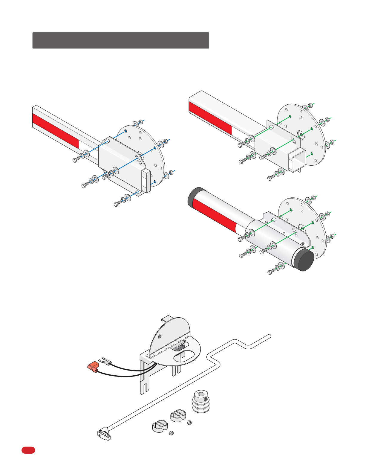
SECTION 4 - ARM INSTALLATION
Arm installation varies depending on the operator model and individual installation requirements. All operators are equipped
with 2 hub connections on opposite sides of the operator.
The 1601 operates with a single 14 ft. arm (either straight or folding arm). The 1601 can not operate with the 20 ft. to 27 ft.
3-piece arm assemblies.
The 1602 operator is designed for the 3-piece 20 ft. to 27 ft. arm assemblies only.
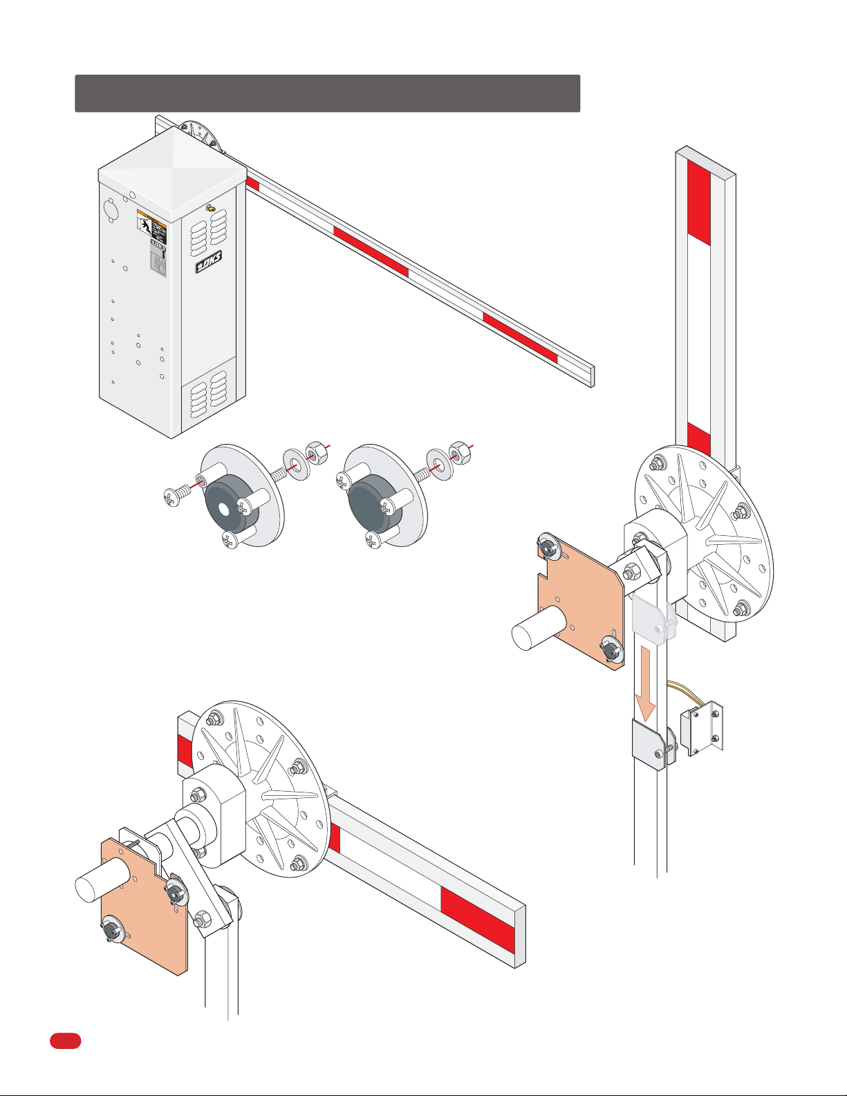
4.1 Mounting Hub(s)
Mount hub(s) as shown with operator in the DOWN position.
A single hub should be mounted on the opposite side of
oncoming traffic.
Arm Direction
Vertical
Hub
Screw
Horizontal
Bolt
Locking
Plate
CO
N
FO
AN
R
MS TO
S
I
/
U
L-325
CA
CER
N
/
TI
C
FI
SA C22.2 NO
ED
VE
H
ICU
CLA
L
A
R
SS
MOD
EL
SERI
A
L
VO
LTS
AMPS 60 Hz
M
AX GA
T
E LO
AD
DoorKi
n
g,
I
nc
Second Hub
T
O
53382
. 247
G
AT
E
OP
E
R
A
T
O
H
R
P
PH
A
SE
.
,
I
nglewoo
d
,
CA
Arm Direction and Bracket Hole Positions
Arm Direction
Horizontal
Note: If your installation does NOT allow the
arm to mount in this direction, see Section
5.3, (page 24) to reverse factory setup.
18
Vertical
Plastic/Aluminum
bracket holes
(See next page).
Hub
Wood bracket holes
(See next page).
Hub in the DOWN position.
1601-065-G-6-12
Page 21

4.2 Mounting Arm(s)
Wood Arm Bracket
14 Ft. Arm
Plastic Arm Bracket
12 Ft. Arm
Aluminum Arm Bracket
Test hub UP and DOWN position
before installing arm(s).
14 Ft. Arm
4.3 1602 3-Piece Arm Assemblies
Counter-balance weights are mandatory and MUST be installed on any style arm.
Counter-balance
Weights
Make sure NO overhead high voltage power wires are
within 10 ft of the aluminum arm in the raised position.
See instruction sheet that comes with
the arm kit for assembly.
20, 24 and 27 Ft.
The two arms must
extend back 14 inches
behind the hub to install
the counterbalance
weights.
Connect weights together
with 6 bolts on each arm.
1601-065-G-6-12
Keep all debris (Snow and Ice)
off of arms during operation.
Connect the 3 arms
together with 3 bolts.
Damage could occur to operator.
20 Ft. Wood Arm Assembly
Aluminum Arm
Assembly
19
Page 22

SECTION 5 - ADJUSTMENTS
P
N
The switch settings and adjustments in this chapter should be made after your installation and wiring to the operator is
complete. Whenever any of the programming switches on the circuit board are changed, power must be shut-off, and then
turned back on for the new setting to take effect.
5.1 1601 Circuit Board Description and Adjustments
Gate Tracker
Activity LED
An automatic sensor
system that senses
entrapment of a solid
object and is incorporated as a permanent
and integral part of the
Gate Operator
Data Terminal
Operator status
reporting; cycle count,
shorted inputs, loop
detector problems,
power interruptions, etc.
See page 11.
operator.
Single Channel Loop Detector
9410
DoorKing Plug-In
Loop Detectors
(Sold separately)
UP
LOOP
Up Loop PortDown Loop Port
Auto Close Timer
Auto close timer (when
turned on) SW 1, switch 7.
Adjust from 1 second (full
counter clockwise) to
approximately 59 seconds
(full clockwise).
TIME
DELAY
ON
2 3 4 5 6 7 8
SW 1
ON
1
Power
LED
1601-010
2 3 4 5 6 7 8 1
POWER
SW 2
ON
1
2 3 4 5 6 7 8
SW 1
159
Up Limit LED
Down Limit LED
Limit
Sensor
See page
25.
How LEDs Function
Illuminated LEDs Indicates that
low voltage power is being
applied to the circuit board.
Input LEDs should be OFF and will
only illuminate when the input is
activated.
Limit LEDs will only illuminate when
the respective limit sensor has been
activated.
1
Self Test
Self test (when
turned on) SW
1, switch 2.
DIP-Switches
Set the DIP-switches on
the circuit board to the
desired setting. See
switch settings information on the next 3 pages.
Note: SW 2, switch 1
MUST be set for the
correct model operator
that has been installed.
2 3 4 5 6 7 8
1
2 3 4 5 6 7 8 1
2 3 4 5 6 7 8
SW 1
SW 1
SW 2
ON
ON
ON
Arm Relay Contacts
(C – NC – NO) This relay can be used for a
variety of purposes and is typically used to
DOWN
LOOP
REVERSE
SENSITIVITY
signal when the arm is up or down.
ON
Dry Relay Contact
N.O.
N.C.
Relay activation is
dependant on
setting of SW 1,
switch 5.
Down Terminals Up Terminal
9409
Dual Channel Loop Detector
Input LEDs
NC NO
123456789101112 13 14
Reverse Sensor
Adjust reversing
sensitivity for the
DOWN direction of
arm.
See page 25.
Min Max
20
Dry relay contacts (terminals 12-13) can be
set for Normally Open (NO) or Normally
Closed (NC) operation by placing the relay
shorting bar on the N.O. or N.C. pins
respectively. See page 10 and next page.
1
2 3 4 5 6 7 8
SW 1
1601-065-G-6-12
Page 23

5.2 DIP-Switch SW 1 and SW 2 Settings
The two DIP-switches located on the circuit board are used to program the operator to operate in various modes and to turn on
or off various operating features. Whenever a switch setting is changed, power to the operator must be turned OFF and then
turned back on for the new setting to take affect. Check and review ALL switch settings prior to applying power to the operator.
SW 1 (Top 8 Switches)
Switch Function Setting Description
Down Active when arm
is full up.
1
Down Active when arm
is moving up or is up.
2
3
4
5
6
7
8
Up Loop Port Input
Self-Test
Gear Box Travel
Down / Reverse
Loop and Input
Relay 1 Activation
Up Input Function
Timer
OFF
OFF
OFF
OFF
OFF
OFF
OFF
OFF
Activation and then deactivation of the down loop or down / reverse input will cause the arm to rotate
down ONLY if the deactivation occurred after the arm reached the FULL UP position.
Activation and then deactivation of the down loop or down / reverse input will cause the arm to rotate
ON
down AFTER reaching the FULL UP position regardless of when the deactivation occurred.
Normal setting. Self-test is turned off.
Run self-test.
ON
Normal setting. Operator uses 360° of gearbox. Extends wear life of gearbox.
Operator uses 180° of gearbox.
ON
Down / Reverse loop and input will function as a REVERSE loop and REVERSE input.
Normal setting. Down / Reverse loop and input will function as a down input and cause the arm to
ON
rotate down upon deactivation of the input. See SW 1, switch 1 for additional information.
Normal setting. Relay activates when the DOWN loop detector (DoorKing plug-in detector only) senses
a vehicle presence.
Relay activates when the UP loop detector (DoorKing plug-in detector only) senses a vehicle presence.
ON
Up Input will raise arm and/or reset the down timer. Input will not lower the arm.
Up Input will raise arm if it is down, or will lower arm if it is up.
ON
Timer to lower arm is OFF.
Timer to lower arm is ON. Set from 1 to 59 seconds for close time delay. Timer can be used as a
ON
secondary closing command for a down loop. Timer countdown starts when arm has fully raised.
Down loop activation will cancel timer and lower arm OR arm will lower when timer has timed out.
Output of the loop detector plugged into the UP loop port is switched to terminal 7 for connection to
other input terminals.
Normal setting. Output of the loop detector plugged into the UP loop port will raise arm when
ON
activated.
SW 2 (Bottom 8 Switches)
Switch Function Setting Description
1
2
3
4
5
6
Model 1601
Model 1602
Multiple Input Memory
ON/OFF Switch
Multiple Input
Memory Options
(SW2, Switch 2 must be ON)
(SW1, Switch 4 must be ON)
Stop Arm Function
Reverse Delay
Arm Rotation Direction
7
8
Spare
Spare
OFF
ON Switch must be ON for model 1602 barrier gate operator.
OFF
ON
Option 1
(OFF Position)
Option 2
(ON Position)
OFF
ON
OFF
ON
OFF
OFF
OFF
Switch must be OFF for model 1601 barrier gate operator.
Normal setting. Operator will respond to a single UP command, then require a DOWN command.
Operator will not accept multiple Up commands. Operator will not accept the next UP command until
the previous DOWN command is in progress.
Turns ON the multiple input memory option 1 or 2 (See switch 3). SW 1, switch 4 must also be on.
Override a DOWN command – When the arm is in the up position for a vehicle passing through and the
next vehicle’s UP command is received, the operator will hold the arm up and wait for the next vehicle
to clear the down loop before lowering the arm. The operator will not count multiple UP commands.
Distance between access control device and barrier operator is a factor when using this option. Remote
transmitters recommended for this option. See next page for more information.
Override Mulitlpe DOWN commands – The operator will count multiple UP commands received during
an UP command and require a matching number of DOWN commands before lowering the arm.
Distance between access control device and barrier operator is a factor when using this option. Remote
transmitters NOT recommended for this option. See page 23 for more information.
Normal setting. Arm will NOT stop DURING the down cycle.
Stop Arm Function – Arm will stop DURING the down cycle if a vehicle activates the down loop.
An UP command will raise the arm, or the arm will continue down AFTER the down loop is cleared.
Arm reversal is delayed approximately .5 seconds when a reverse input from terminal 9 is received
during the down cycle. (eg. non-contact sensor beam is blocked). Limited application use.
Normal setting. Instant Reverse – Arm reversal is delayed approximately .1 second when a reverse
input from terminal 9 is received during the down cycle. (eg. non-contact sensor beam is blocked)
Normal setting. Leave in OFF position.
Normal setting. Leave in OFF position.
Normal setting. Leave in OFF position.
1601-065-G-6-12
21
Page 24

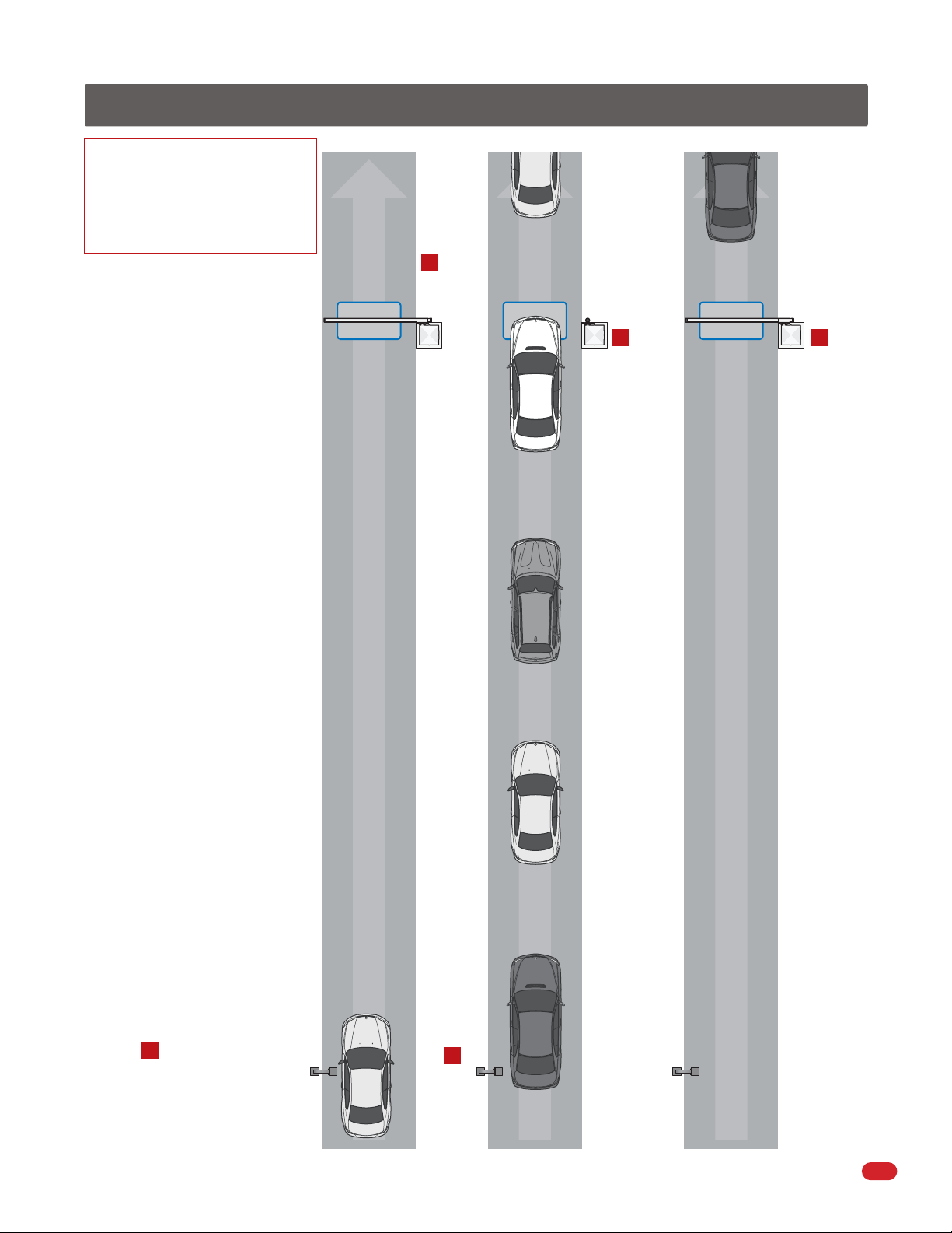
Option 1 - Override a DOWN Command SW2, Switch 3 OFF
Remote transmitters are recommended for this option.
Valid UP command given.
1
Access Control Device
1st Car
Note: Operator will NOT accept
another valid UP command until
“1st Car” activates down loop.
12 Ft. Maximum Distance
Option 1 CANNOT be used
at distances OVER 12 feet.
This allows multiple vehicles
in this area which Option 1
WILL NOT keep track of.
See Option 2 on next page.
1st Car
Basic operator UP/DOWN cycle:
A. Valid UP command from the
access control device will raise arm.
B. Vehicle activating and clearing
Down Loop
2
Down Loop
the down loop will lower the arm.
Operator will raise arm.
Next Car
While 1st Car is on down loop,
4
the next UP command is given.
1st Car activates down loop.
3
1st Car
Next Car
Operator will override “1st Car’s”
5
DOWN command. Arm will remain up
and wait for the “Next Car’s” down loop
to be activated.
Down Loop
1st Car
Note:
If an UP command is given while the arm is lowering, the arm will raise.
22
When “Next Car” activates then clears
6
down loop, arm will lower.
1601-065-G-6-12
Page 25
Option 2 - Override Multiple DOWN Commands SW2, Switch 3 ON
Basic operator UP/DOWN cycle:
A. Valid UP command from the
access control device will raise arm.
B. Vehicle activating and clearing
the down loop will lower the arm.
This option allows the access
control device and the barrier gate
operator to have multiple vehicles
in the area between them. The
operator will count all the valid UP
commands received and require a
down loop activation for each one.
The arm will lower only after the
last vehicle activates then clears the
down loop.
Remote transmitters are NOT
recommended for this option
because one vehicle’s remote can
accidently be pressed multiple
times which will get counted by the
operator as multiple vehicles.
Down Loop
2
Operator
will raise
arm
1
Down Loop
2
3
5
Down Loop
4 5
Operator will
override
multiple
DOWN
commands.
Arm will
remain up
while counting
the vehicles
activating
the down loop.
Operator will
lower the arm
ONLY after the
last vehicle
activates
then clears
the down loop.
Note:
If an UP command is given
while the arm is lowering, the
arm will raise.
Valid UP command given
1
1601-065-G-6-12
Access Control Device
4
5
Operator will count each valid UP command from each vehicle as they enter.
3
1
23
Page 26
5.3 Reverse Arm UP and DOWN Positions
The operator has been setup from the factory to have the access door opposite the traffic lane.
If the operator has been installed with the access door facing the
traffic lane, the am will operate in the reverse direction from
the factory setup. The UP and DOWN magnet positions
must be reversed on the limit plate.
CO
N
FO
A
R
N
M
S
I/U
S
TO
L
-
32
C
CE
A
N
RTIFIED
/
C
SA
C
T
V
2
2.
E
H
2
I
N
CU
C
L
LA
AR
SS
G
AT
M
O
D
EL
S
ER
IAL
V
O
L
T
S
AM
P
S
M
A
X
G
A
T
E L
O
A
D
D
o
o
rKin
g
, I
n
c., I
Note: Magnets
can be removed
from assemblies
with 3 screws
and flipped over
to show or hide
the white dot.
5
O
O
5
.
3
24
3
8
2
7
E
O
PE
R
A
T
O
H
R
P
PH
A
SE
6
0
H
z
n
g
le
wo
o
d
,
C
A
Access
Door
Facing
Traffic
DOWN Assembly
UP Assembly
Magnetic Limit Assemblies
Reverse the positions of the magnets on the limit plate.
The white dot will be visible on the DOWN assembly
magnet ONLY.
Be careful when reversing assemblies
not to damage circuit board.
Operators equipped with the convenience
open system must adjust the DC
limit assembly (See below).
UP
Position
of Limit
Plate
Arm Shaft
DOWN
Limit Plate
UP
Factory
Position
DOWN
Position
of Limit
Plate
24
Arm Shaft
UP
Limit Plate
DOWN
DC Limit
Assembly
DC Limit
Sensor
Linking Arm
Convenience Open System
Slide the DC limit assembly down
the linking arm to align with the
DC limit sensor when the arm is
in the UP position.
Note: DC limit sensor is used to
hold the arm in the UP position
during an AC power failure.
1601-065-G-6-12
Page 27

5.4 Magnetic Limit Adjustments
The operator has been preset at the factory to rotate 90°. No adjustments are necessary when used in a normal 90° setup.
If the arm needs to rotate less than 90°:
Turn operator power OFF.
1
Set the DIP-switch SW 1, switch 3 to ON.
2
This changes the rotation of the gearbox
from 360° to 180° allowing the gearbox
to rotate the arm less than 90°.
Note: The arm will always cycle to 90°
open with the 360° gearbox setting.
Loosen magnet limit assembly nuts and slide the
3
assemblies to the desired UP and DOWN positions.
Tighten nuts when desired positions are achieved.
TIME
DELAY
1601
UP
LOOP
ON
1
2 3 4 5 6 7 8
SW 1
UP Limit
DOWN Limit
Magnetic Limit
Sensor
Magnet
Limit
Assembly
(White Dot)*
Magnet Limit
Assembly
(No White Dot)*
DOWN
Limit
3
3
UP
Limit
Arm Shaft
Down Up
*Factory Magnet Setting
5.5 Reverse Sensor
Reverse sensitivity adjustment will cause the barrier arm to reverse direction of travel should an object be encountered during
the down cycle. The amount of force required for the arm to reverse direction depends on the reverse sensitivity potentiometer.
CAUTION: Keep pedestrians and vehicles clear of the arm zone while adjusting sensor!
TIME
POWER
DELAY
2 3 4 5 6 7 8
SW 1
1
2 3 4 5 6 7 8 1
SW 2
NC NO
ON
ON
While operator has AC power:
Turn control switch to UP. Arm will rotate UP.
1
Turn control switch to DOWN. While arm is
2
traveling down, rotate reverse sensor clockwise
until the reverse LED lights up and the arm
reverses direction. Rotate reverse sensor back
counterclockwise approximately 1/8 turn.
Repeat the adjustment as needed to find a
3
satisfactory setting.
UP
UP
AUTO
DOWN
UP
AUTO
LOOP
DOWN
REVERSE
SENSITIVITY
Min Max
DOWN
LOOP
1601
REVERSE
SENSITIVITY
1601-065-G-6-12
1234567891011121314
25
Page 28
5.6 Manual Operation of the Arm
When a power failure occurs in an operator WITHOUT the convenience open feature with the arm (3-piece arm for the 1602) in
the down position and the pathway needs to be open, the arm MUST be unbolted from the hub with 4 bolts and removed to
clear the pathway. A manual release kit is offered from DoorKing to phisically crank the arm up if desired (See below).
Operators WITH the convenience open feature can be set to automatically open the arm(s) during a power failure.
Plastic Arm Bracket
Wood Arm Bracket
Hub
“Optional” Manual Release Kit
Hub
Aluminum Arm Bracket
Hub
DoorKing offers a kit designed to be installed on the 1601 or 1602 barrier gate operators WITHOUT the convenience open
feature. It provides a crank tool to manually move the arm up or down. DO NOT install on convenience open models. For
further information about this kit, refer to the instruction sheet provided with the kit (P/N 1601-270) or go to DoorKing’s
technical web site at: www.dkaccess.com.
26
1601-065-G-6-12
Page 29

SECTION 6 - OPTIONAL CONVENIENCE OPEN SYSTEM
The optional convenience open system installed in your vehicular gate operator is designed as a convenience enhancement only.
It is not designed or intended to provide continuous gate operation during a power outage. Its sole purpose is to provide a
method to open the vehicular gate to allow unimpeded traffic flow when the gate and access control system is without power. If
your access control system requires 100% power backup and continuous operation when primary (AC) power has failed, a
power inverter / backup system, such as DoorKing’s Models 1000 or 2000, is required.
• The convenience open system cannot provide continuous gate operation during a power outage.
•
This system cycles the arm to the open position one time only after AC power failure.
• The convenience open system requires testing on a monthly basis to insure the batteries are fully charged and that the
system is operational.
• The convenience open system uses two 12-volt, 3.0 amp-hour gel-cell batteries. These batteries should be replaced
every two years on average, or sooner if required.
• Batteries are affected by temperature. Cold temperatures will reduce the effectiveness of the batteries. High temperatures
will result in a shortened battery life.
• Batteries are not covered under warranty.
6.1 Operating Mode
This convenience open system consist of a control board (2340-010), motor and power supply (batteries) providing a
completely redundant drive system to open the barrier arm should a power outage occur. This system is not designed to
maintain continuous barrier operation; rather it provides a convenient method to open the arm once during adverse conditions.
If continuous barrier and access control system operation is required, refer to the DoorKing Models 1000 or 2000 Inverter /
Backup Power System.
Automatic Open after loss of AC Power
Turn switch 1 ON and the system will automatically
2340
open the arm approximately 3 seconds after loss of
AC power. Automatic mode is always used for
barrier arms in general access applications such as
gated communities, apartment complexes, etc.
Switch 1 OFF is not used.
1ON2 3 4 5 6 7 8
DIP-Switches
Restart Options once AC Power is restored
Once AC power is restored, the system’s control
board can be set to “automatically re-key” the
operator (switch 3 ON) to establish normal
operation, or can be set to require a “manual
input” (switch 3 OFF) before the operator resumes
normal operation.
1ON2 3 4 5 6 7 8
DIP-Switches
Initial Power Up Convenience Open Note: The DC power is not present on the main circuit board until the first initial cycle.
1601-065-G-6-12
27
Page 30
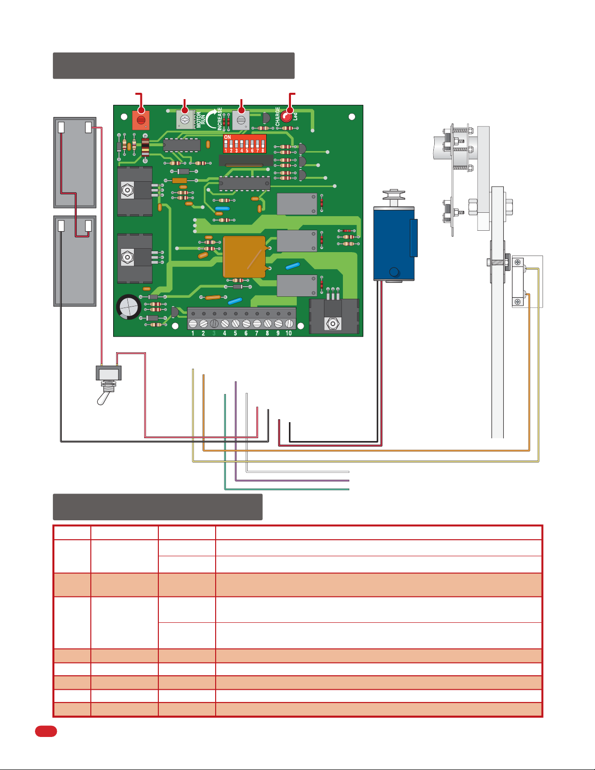
6.2 DC System Description
Do Not Adjust Do Not Adjust Timer Not Used Charging LED
Batteries
+
3 Amp/Hr
+
3 Amp/Hr
Red/White
DIP-Switches
Activation Output
Radio Power Not used.
Open Input
Common
24 VAC Common
24 VAC Input
DC Motor Negative Output
DC Motor Positive Output
Battery Negative Input
Battery Positive Input
–
12 V
Red
–
12 V
DC ON/OFF
Power Switch
Black/White
Red/White
2340
Black
White to Main Terminal #14
Purple to Main Terminal #5
Green to Main Terminal #8
Arm Rotation Assembly
in UP Position
DC Motor
Red
Arm will cycle to UP
position automatically
during an AC power
failure. DC limit sensor
will hold the arm in
the UP position.
DIP-Switch 3 setting
will determine how
arm will return to
normal operation once
AC power has been
restored.
DC Magnet
Limit Assembly
(Adjusted at Factory)
DC Limit
Sensor
Orange
Yellow
6.3 DIP-Switch Settings
Switch Function Setting Description
Not Used
OFF
1
2
3
4
5
6
7
8
28
Operation
Changes
Open Direction
Automatic
Power-up
Activation
Operator Type
Not Used
Not Used
Not Used
Not Used
ON
Arm will automatically open when a power outage occurs.
OFF
Set so that the arm runs to the open (up) direction upon loss of AC power.
When AC power is restored, an input (push button, loop, radio receiver, etc.) is
OFF
required to return the arm to normal operation.
When AC power is restored, a 1-second pulse is sent to the gate operator input to
ON
automatically restore normal operation.
Must be in the ON position.
ON
OFF
OFF
OFF
OFF
1601-065-G-6-12
Page 31

SECTION 7 - OPTIONAL ACCESSORIES INSTALLATION
7.1 Contact Sensor (Reversing Edge)
In addition to the electronic reversing device (ERD) an optional electric reversing edge (P/N 8080-016) may be installed offering
additional protection to the arm, operator and obstruction.
Mounting Channel
Reversing Edge
Turn operator power OFF.
1
Center and secure the 6-foot mounting
2
channel to the bottom of the barrier arm
using 3/4-inch wood screws (not supplied).
Slide the reversing edge into the mounting
channel.
Drill a 1/4-inch hole on the side of the
3
operator housing beneath the
operator arm shaft.
UP
LOOP
TIME
DELAY
CONF
ORMS TO
ANSI/UL-325
CAN/C
CE
R
T
SA
C22
V
EHICULA
C
L
AS
S
MODE
L
S
E
RIAL
V
OL
TS PHAS
A
M
PS
MAX
GA
TE LOAD
D
o
o
r
Kin
IF
I
E
D
T
O
.2
NO.
5
33
2
82
47
R
G
A
TE O
P
ERA
T
O
HP
R
E
60
Hz
g
,
In
c
.
,
In
g
le
w
o
o
d
,
CA
DOWN
LOOP
123456789 10 11 12 13 14
Connect wires to terminals 9 and
6
14 without interfering with any of
the operator’s moving parts.
1601-065-G-6-12
REVERSE
SENSITIVITY
N.O.
2 3 4 5 6 7 8
SW 1
1
2 3 4 5 6 7 81
POWER
SW 2
1601
NC NO
ON
ON
Com
Reversing Edge Assembly
Wire Ties
Install a plastic grommet
4
(Not supplied) in the
hole to protect the wire
from chaffing on sharp
metal edges.
Secure the wire to the arm and hub
5
using wire ties (not supplied). leave
a wire loop to allow the arm to
rotate freely.
Wire Tie
Wire Loop
Plastic
Grommet
C
O
N
F
O
ANS
R
M
I/
S
U
T
L
O
3
C
CE
2
A
5
N
R
/C
T
IF
S
I
A
E
D
C
V
2
T
2
E
O
.
H
2
I
N
C
O
U
5
.
3
C
3
L
2
8
L
A
2
4
A
7
R
S
S
G
AT
E
M
OP
O
D
E
E
L
R
AT
S
O
E
H
R
R
P
I
A
L
V
O
L
T
S
A
M
P
S
M
A
P
X
H
GAT
A
S
E
E
L
O
A
Doo
6
D
0
H
r
K
z
i
n
g
,
I
n
c
.
,
I
n
g
l
e
w
o
o
d
,
CA
29
Page 32

7.2 Fan Kit
An optional fan kit (P/N 1601-093) is recommended in hot humid
climates to prevent heat and moisture build-up inside the housing.
Shut off AC power to operator.
1
Turn off DC power switch on certain models.
Lock Nut
Lock Nut
Mount fan using 3 existing
2
threaded studs and lock
nuts supplied. Slide
Route fan wires as shown. Use supplied
3
wire stays and existing wire restrainers.
Keep wires clear of all moving parts.
mounting tabs over
existing air duct.
Housing Studs
Lock
Nut
Threaded
(Existing)
Mounting
Tab
Mounting
Tab
Existing
Air Duct
Threaded
Air Duct
Stud
(Existing)
4
Existing Wire Restrainers
3
Wire Stays
Connect the fan power wires according to operator model type.
4
DANGER
Exhaust Vents
HIGH VOLTAGE!
1
2
5
Air
Flow
Neutral
Hot
115 VAC Models
Fan switch settings.
5
OFF - Turns the fan off.
ON - Turns the fan on continuously.
1212 345
230 VAC/460 VAC Models
Neutral
115 VAC Hot
Neutral
AUTO - Normal setting. Automatically turns the fan
ON when the temperature rises above 90°F inside the
housing, and turns the fan OFF when the temperature
drops below 90°F.
g
Existin
Air Duct
Intake Vents
Keep intake vents clear of debris.
30
1601-065-G-6-12
Page 33

7.3 Heater Kit
To avoid the gearbox oil from freezing an optional heater kit (P/N 1601-092) is recommended in areas where temperatures
routinely drop below 40°F (4°C).
Shut off AC power to operator.
1
Turn off DC power switch on
certain models.
Route heater wires as shown. Use supplied
3
wire stays and existing wire restrainers.
Keep wires clear of all moving parts.
Mount heater with 2 lock nuts.
2
Place the 2 supplied
washers between the
operator wall and
the heater to
create an
air gap.
Lock Nut
CAUTION: Heat will be
transferred to the outside
wall of the operator if NO
air gap exists between the
heater and the inside wall
of the operator.
Washer
Threaded
Housing Stud
(Existing)
Threaded
Housing Stud
(Existing)
ire Restrainers
W
xisting
E
Washer
DANGER
HOT!
1
Air Gap
Connect the heater wires according to operator model type.
4
4
2
Neutral
Lock Nut
HIGH VOLTAGE!
Hot
DANGER
1
Neutral
Neutral
212 345
115 VAC Hot
5
115 VAC Models
Heater switch settings.
5
3
Wire
Stays
230 VAC/460 VAC Models
AUTO
- Normal setting. Automatically turns the
heater ON when the temperature drops below 40°F
inside the housing, and turns the heater OFF when
the temperature rises above 40°F inside the housing.
OFF - Turns the heater off.
1601-065-G-6-12
ON - Turns the heater on continuously. The heater
will become VERY HOT when running continuously.
31
Page 34

SECTION 8 - MAINTENANCE AND TROUBLESHOOTING
Inspection and service of this gate operator by a qualified technician should be performed anytime a malfunction is observed or
suspected. High cycle usage may require more frequent service checks.
8.1 Maintenance
When servicing the gate operator, always check any secondary (external) reversing devices (loops, photo eyes, etc.) for proper
operation. If external reversing devices cannot be made operable, do not place this operator in service until the malfunction can
be identified and corrected.
Always check the inherent reversing system when performing any maintenance. If the inherent reversing system cannot be
made operable, remove this operator from service until the cause of the malfunction is identified and corrected. Keeping
this operator in service when the inherent reversing system is malfunctioning creates a hazard for persons which can result
in serious injury or death should they become entrapped.
When servicing this gate operator, always turn power OFF!! If equipped with batteries, make sure battery power switch is OFF.
If gearbox requires oil, use only Mobil SHC-629 Synthetic Gear Oil. Do not completely fill gearbox with oil. Gearbox is full
when oil completely covers inspection window.
Operator
Component
Arm
(s)
Drive Belt
ERD Reversing System
Batteries
(On select models)
Convenience Open System
(Not on all models)
Fire Dept.
Gearbox
Linkages
Loop(s)
Pulleys
Secondary Reverse
Device(s)
Complete System
(s)
Maintenance
Check for alignment, tightness and wear.
Check for alignment, tightness and wear.
Check that the arm reverses on contact with an object in closing
cycle. Adjust the reversing sensor if necessary.
If operator is equipped with optional convenience open system,
check the batteries for any leakage or loose connections.
Batteries should be replaced every two years.
If operator is equipped with optional DC open system, check to
be sure the system opens the arm upon loss of AC power.
Operator should resume normal operation when AC power has
been restored.
Check emergency vehicle access device for proper operation.
Check oil level and fill if necessary. Do not overfill.
Check internal linkages for wear. Inspect bushing for wear.
Check all external ground loops for proper operation.
Check set screw for tightness.
Check electric reversing edges and photo-cells for proper
operation.
Perform a complete system check. Include all reversing devices,
loops, access system devices, Fire Dept. access devices, etc.
Monthly Interval
6 3 12
✓ ✓
✓ ✓
✓
✓
✓
✓ ✓ ✓
✓ ✓
✓
✓ ✓
✓ ✓
✓ ✓
✓ ✓
✓
32
1601-065-G-6-12
Page 35

8.2 Diagnostics Check
Have the following diagnostic tools available: VOM meter with minimum voltage memory or min-max range to check voltage
and continuity. Meg-ohm meter capable of checking up to 500 megohms of resistance to properly check ground loop integrity.
A malfunction can be isolated to one of the following:
• Gate Operator
• Loop System
• Keying Devices
Disconnect all external inputs to the circuit board terminal.
1. Use caution when checking high voltage areas: terminals 1 through 6, the motor capacitor and the motor.
2. Check the input indicator LED’s. They should only come ON when a keying device (card reader, push button, etc.) is
activated. If any of the input LED’s are ON continuously, this will cause the gate operator to hold the arm up. Disconnect the
keying devices one at a time until the LED goes OFF (see troubleshooting guide).
3. If the operator stops or holds open, check external secondary entrapment protection devices for any shorts or malfunction.
4. A malfunction in a loop or loop detector can cause the gate operator to hold the arm up, or not detect a vehicle when it is
present over the loop. Pull the loop detector circuit boards from the loop ports on the operator circuit board. If the malfunction
persists, the problem is not with the loop system. For more information refer to the loop detector instruction sheet and the
DoorKing Loop and Loop Detector Information Manual.
5. Check that there are no shorted or open control wires from the keying devices to the gate operator. If a keying device fails
to open the arm, momentarily jumper across terminals 6 and 14 on the control board terminal. If the gate operator starts, this
indicates that a problem exist with the keying device and not with the gate operator.
6. Check the supply voltage and batteries. A voltage drop on the supply line (usually caused by using wires that are too small)
will cause the operator to malfunction. Batteries should be fully charged for proper operation, replace batteries every two years
on average.
8.3 Troubleshooting
Symptom Possible Solution(s)
• Check that power to the operator is turned ON.
Operator will not run.
Power LED is OFF.
• Check for 117 VAC with a voltmeter at control board terminals 1 and 2. If voltage measures 0,
check power supply to operator or check terminal strip. If voltage measures OK, replace control
board.
1601-065-G-6-12
33
Page 36

8.3 Troubleshooting Continued
Symptom Possible Solution(s)
• Momentarily jumper terminal 6 to terminal 14. If input LED does not come ON, check terminal strip
Operator will not
run. Power LED
is ON.
Arm rotates up,
but will not
rotate down.
or replace control board. If LED does come on, go to the next step.
• Momentarily jumper terminal 2 to terminal 3 (Caution – High Voltage). The motor should run.
• Momentarily jumper terminal 2 to terminal 4 (Caution – High Voltage). The motor should run in
opposite direction of above.
• If motor does not run in either or both steps above, bad motor, motor capacitor or wiring to motor.
• Check LEDs on terminals 6, 7 and 9. Any of these ON will hold the arm in the UP position. This
indicates a shorted input.
• Check the LEDs on the loop detectors. Any ON will hold the arm in the UP position. Possible loop or
loop detector problem.
• If auto timer is not used (SW 1, switch 7 off ), check to be sure SW 1, switch 6 is in the ON
position. This will cause terminal 6 to rotate the arm down when it is activated.
• Check to be sure SW 1, switch 4 is ON. This will cause terminal 8 activation, then deactivation to
rotate arm down.
Down input / down
loop will not rotate
arm to down
position.
Loop detector LED
is on continuously.
Loop detector LED
never activates.
Battery back-up
system will not
raise arm upon
power outage.
• Check to be sure, switch 4 is in the ON position.
• Down input must be activated, and then deactivated to cause arm to rotate down.
• Activate the reset switch on the loop detector.
• Decrease loop detector sensitivity.
• Check loop wire for resistance to ground with meg-ohm meter. Should be 100 meg-ohms or higher.
If less than 50 meg-ohms, replace loop wire.
• Be sure loop lead-in wire is twisted at least 6 turns per foot.
• Be sure all loop connections are soldered.
• Replace loop detector.
• Increase loop detector sensitivity.
•
Check continuity of loop wire. Should be 0 ohms. If continuity check indicates anything other than
0 ohms, check all connections. Replace loop wire.
•
Move loop detector board to the other loop detector port on the control board, and then check loop
operation. If loop detector still fails, replace loop board.
•
If loop detector operates OK in the other loop port, replace control board.
• Check that the back-up system toggle switch is in the ON position.
• Check to be sure that the 2340-010 battery back-up control board switch settings are set as
described in SECTION 6.
• Check the batteries for proper voltage, replace if necessary.
• Replace the 2340-010 Back-up control board.
34
1601-065-G-6-12
Page 37

8.4 Accessories Parts List
The following accessories are available for 1601 and 1602 barrier gate operators.
Loop Detector - Plug directly into ports on circuit board simplifying wiring.
P/N 94010-010 - Single channel detector.
P/N 9409-010 - Two channel detector.
Loop Wire - XLPE insulation is available in 500 and 1000 foot rolls, available in Black, Blue and Red insulation.
Loop Sealant
P/N 2600-771 Asphalt
P/N 2600-772 Concrete
Manual Release Kit for the 1601 or 1602 - Installs on operators WITHOUT the convenience open. P/N 1601-270
Meg Ohm Meter - Checks the integrity of ground loops. P/N 9401-045
Interconnection Cable - Interconnection cable contains all the necessary wires to interconnect primary / secondary operators.
Cable length: 30 ft. - P/N 2600-755 40 ft. - P/N 2600-756 50 ft. - P/N 2600-757
Reverse Edge - Installs on the bottom of the arm. P/N 8080-016
Photo Cell - Prevents arm from lowering on vehicles or pedestrians. P/N 8080-018
Manual Gate Control Toggle - Allows user to manually operate gate arm. Fits inside single-gang electrical box. P/N 1200-017
Time Clock - 7 and 365 day clocks, used to automatically open gate at pre-set time, fits inside operator.
P/N 2600-791 7 day clock
P/N 2600-795 365 day clock
Surge Devices - Helps prevent circuit board failure caused by lightning strikes and power surges.
P/N 1876-010 - High Voltage
P/N 1878-010 - Low Voltage
Replacement Battery - Convenience open system. P/N 1801-009 (2 required)
Speed Bump - Prefabricated 6-foot speed bump reduces traffic speed through gate system. P/N 1610-150
Heater Kit - Thermostatically controlled heater for cold weather areas. P/N 1601-092
Fan Kit - Thermostatically controlled fan for hot humid environments. P/N 1601-093
Gate Tracker™ - Optional control board allows the barrier gate operator to report activity to a companion 1833, 1835, 1837 or
1838 access control system.
Wood Arm Only - 14-foot replacement wood arm. P/N 1601-348
Wood Arm Mounting Kit - Wood arm mounting bracket, hub and mounting hardware. P/N 1601-240
Wood Folding Arm Kit - Low headroom applications (Arm included). P/N 1601-384
Plastic Arm Only - 12-foot replacement plastic arm. P/N 1601-571
Plastic Arm Mounting Kit - Plastic arm mounting bracket, hub and mounting hardware. P/N 1601-241
Plastic Folding Arm Kit - Low headroom applications (Arm included). P/N 1601-383
Aluminum Arm Only - 14-foot replacement aluminum arm. P/N 1601-516
Aluminum Arm Mounting Kit - Aluminum arm mounting bracket, hub and mounting hardware. P/N 1601-242
Aluminum Folding Arm Kit - Low headroom applications (Arm included). P/N 1601-610
20 Ft 3-Piece Aluminum Arm Kit - For the 1602 barrier gate operator ONLY. P/N 1602-162
24 Ft 3-Piece Aluminum Arm Kit - For the 1602 barrier gate operator ONLY. P/N 1602-164
27 Ft 3-Piece Aluminum Arm Kit - For the 1602 barrier gate operator ONLY. P/N 1602-166
(Aluminum arm mounting brackets, hubs and mounting hardware included in all 3-piece aluminum arm kits)
20 Ft 3-Piece Wood Arms Only - For the 1602 barrier gate operator ONLY. P/N 1602-340
20 Ft 3-Piece Wood Arms Mounting Kit - Wood arm mounting brackets, hubs and mounting hardware for 20 ft 3-piece wood
arms. P/N 1602-041
Foam Padding for 14 Ft Arm - Foam padding for the aluminum or wood arm. P/N 1601-260
1601-065-G-6-12
35
Page 38

1/2 or 1 HP 115 VAC
UP
LOOP
DOWN
LOOP
1601
REVERSE
SENSITIVITY
Up Limit
Magnet
TIME
DELAY
Magnetic
Limit Sensor
ON
2 3 4 5 6 7 8
ON
1
2 3 4 5 6 7 8 1
POWER
Down Limit Magnet
(White Dot)
1601
1/2 HP
Single
Phase
Chassis Ground
White White
NEU HOT
115 VAC
White
Yellow
Orange
1602
1 HP
Single
Phase
White
Blue
Red
Ground
Current Sensor
NC NO
1 2 3 4 5 6 7 8 9 10 11 12 13 14
Com
Black
White
Red
Purple
Blue
Black
Black
Power
Neutral
Ground
36
White
Yellow
Orange
Red
Blue
White
Orange
Yellow
Ground
AC Power UP/Auto/Down
1601-065-G-6-12
Page 39

1/2 or 1 HP 115 VAC / Convenience Open
2340
Black
Red
Black/White
DC Motor
–
12 V
Red
–
Batteries
12 V
+
3 Amp/Hr
+
3 Amp/Hr
Red/White
UP
LOOP
DOWN
LOOP
Current Sensor
1601
REVERSE
SENSITIVITY
Up Limit
TIME
DELAY
Magnetic
Limit Sensor
ON
2 3 4 5 6 7 8
ON
1
2 3 4 5 6 7 8 1
POWER
NC NO
Magnet
Down Limit Magnet
(White Dot)
DC Up Limit
Magnet
Up Limit Sensor
DC Magnetic
Ground
1601
1/2 HP
Single
Phase
White
Yellow
Orange
Purple
Green
White
Orange
Yellow
Red
Blue
White
Chassis Ground
1602
1 HP
Single
Phase
Orange
Yellow
Ground
NEU HOT
1234567891011121314
115 VAC
Red/White
Black
Black
Ground
AC Power UP/Auto/Down
Red/White
DC Power
Com
Power
Neutral
Purple
Blue
Red
1601-065-G-6-12
37
Page 40

1/2 or 1 HP 230 / 460 VAC
UP
LOOP
DOWN
LOOP
1601
REVERSE
SENSITIVITY
Up Limit
Magnet
TIME
DELAY
Magnetic
Limit Sensor
ON
2 3 4 5 6 7 8
ON
1
2 3 4 5 6 7 8 1
POWER
Down Limit Magnet
(White Dot)
NC NO
Ground
Current Sensor
1234567891011121314
Chassis Ground
Com
Blue
Black
Brown
White
Blue
Black
Brown
White
Power
Neutral
Black
White
Step-Down
Transformer
1601-065-G-6-12
NEUNEU HOTHOTHOT
Black
230 / 460 VAC
White
Yellow
Orange
White
Blue
Red
Blue
Black
Ground
1601
1/2 HP
Single
Phase
White
Yellow
Orange
Red
Blue
White
1602
1 HP
Single
Phase
Yellow
Orange
Blue
White
Ground
AC Power UP/Auto/Down
38
Purple
Blue
Red
To White
To Blue
230
VAC
To White
To Blue
460
VAC
Black/White
Black/White
Page 41

1/2 or 1 HP 230 / 460 VAC / Convenience Open
2340
Black
Red
Black/White
DC Motor
–
12 V
Red
–
Batteries
12 V
+
3 Amp/Hr
+
3 Amp/Hr
Red/White
UP
LOOP
DOWN
LOOP
Current Sensor
1601
REVERSE
SENSITIVITY
Up Limit
Magnet
TIME
DELAY
Magnetic
Limit Sensor
ON
2 3 4 5 6 7 8
ON
1
2 3 4 5 6 7 8 1
POWER
NC NO
Down Limit Magnet
(White Dot)
DC Up Limit
Magnet
Up Limit Sensor
DC Magnetic
1601
1/2 HP
Single
Phase
Ground
1601-065-G-6-12
White
Yellow
Orange
Purple
Green
White
Orange
Yellow
Red
Blue
White
Chassis Ground
1602
1 HP
Single
Phase
Orange
Yellow
Ground
NEU NEU HOT HOT HOT
230 / 460 VAC
Red/White
Blue
Black
Blue
White
Ground
AC Power UP/Auto/Down
DC Power
1234567891011121314
Com
Purple
Blue
Red
To White
To Blue
230
VAC
To White
To Blue
460
VAC
Brown
Black/White
Brown
Black/White
Blue
Black
White
Blue
Black
White
Power
Neutral
Black
White
Step-Down
Transformer
39
Page 42

Installation/Owner’s Manual
1601 / 1602
1601 / 1602
1601 / 1602
Barrier Gate Operator
Use this manual for circuit board 1601-010 Revision V or higher.
1601-065-G-6-12
www.doorking.com
DoorKing, Inc.
120 Glasgow Avenue
Inglewood, California 90301
Phone: 310-645-0023
Copyright 2009 DoorKing, Inc. All rights reserved.
Fax: 310-641-1586
U.S.A.
 Loading...