

Page 1

Owner’s Manual
Models 1506 and 1504
Programmable Stand Alone Digital Keypad Entry Devices
DoorKing, Inc.
120 Glasgow Avenue
Inglewood, California 90301
U.S.A.
Phone: 310-645-0023
Fax: 310-641-1586
www.doorking.com
P/N 1506-065 REV D, 1/09
Copyright 2001 DoorKing, Inc. All rights reserved.
Page 2

Page 2 1506-065-D-1-09
Page 3

Use this manual with the following models
1506-080, 1506-081, 1506-082, 1506-083, 1506-084, 1506-085, 1506-086, 1506-090, 1506-091,
1506-092, 1506-093, 1506-094, 1506-095, 1506-096, 1504-080, 1504-082, 1504-083, 1504-084,
1504-085 and 1504-086 Digital Keypad Entry Devices with circuit board 1506-010, Rev G and
Higher.
DoorKing, Inc. reserves the right to make changes in the products described in this manual
without notice and without obligation of DoorKing, Inc. to notify any persons of any such revisions
or changes. Additionally, DoorKing, Inc. makes no representations or warranties with respect to
this manual. This manual is copyrighted, all rights reserved. No portion of this manual may be
copied, reproduced, translated, or reduced to any electronic medium without prior written consent
from DoorKing, Inc.
Permission is granted to reproduce pages 24 and 25 in this manual.
1506-065-D-1-09 Page 3
Page 4

Page 4 1506-065-D-1-09
Page 5

Table of Contents
IMPORTANT NOTICES............................................................................................................................................6
SECTION 1 – INSTALLATION
1.1 Mounting Dimensions...............................................................................................................................7
1.2 Wiring .......................................................................................................................................................9
1.3 Wire Diagram............................................................................................................................................10
1.4 Terminal Identification ..............................................................................................................................11
1.5 Aiphone Intercom Station Connections....................................................................................................12
1.6 Secondary Keypad Wiring........................................................................................................................13
SECTION 2 – PROGRAMMING
2.1 Master Code.............................................................................................................................................15
2.2 Relay Strike Time.....................................................................................................................................15
2.3 X-Strikes Programming ............................................................................................................................15
2.4 Programming Four-digit Entry Codes.......................................................................................................16
2.5 Erasing Individual Four-digit Entry Codes................................................................................................16
2.6 Erasing ALL Four-digit Entry Codes.........................................................................................................16
2.7 Four-digit entry Code Divide Number.......................................................................................................16
2.8 Programming Five-digit Entry Codes .......................................................................................................17
2.9 Erasing Individual Five-digit Entry Codes.................................................................................................17
2.10 Erasing ALL Five-digit Entry Codes .........................................................................................................17
2.11 Five-digit Entry Code Divide Number.......................................................................................................17
2.12 Hold Boundary Programming...................................................................................................................18
2.13 Time Zone 1 Boundary Programming ......................................................................................................18
2.14 Time Zone 2 Boundary Programming ......................................................................................................18
SECTION 3 – OPERATING INSTRUCTIONS
3.1 Four-digit Entry Codes..............................................................................................................................19
3.2 Five-digit Entry Codes..............................................................................................................................19
3.3 Request to Exit Input................................................................................................................................19
3.4 Door Open Input.......................................................................................................................................19
3.5 Hold Feature Operation............................................................................................................................20
3.6 Time Zone Operation ...............................................................................................................................21
SECTION 4 – APPENDIX
4.1 Troubleshooting........................................................................................................................................23
4.2 Data Tables..............................................................................................................................................24
Log Sheet .................................................................................................................................................................25
1506-065-D-1-09 Page 5
Page 6

2.15
IMPORTANT NOTICES
• Prior to starting the installation, become familiar with the instructions, illustrations and wiring
diagrams in this manual.
• Never mount this device to a moving gate or gate panel, or next to a gate that causes
vibration to the fence, such as a spring-loaded pedestrian gate. Continuous vibration from
moving or slamming gates can cause damage to the unit in time.
• WARNING! If this entry system is used to control a vehicular gate with
an automatic gate operator, the entry system must be mounted a
minimum of ten (10) feet away from the gate and gate operator, or in
such a way that a person cannot operate the entry system and touch
the gate or gate operator at the same time.
• Always disconnect power when performing service on the system.
• If the unit is mounted outdoors, be sure that the wiring to the unit is designed for direct under-
ground burial, even if the wire is run inside a conduit.
• Surge suppression is recommended on the low voltage input power line.
• Instruct the end user on the safe and proper operation of this device.
• Instruct the end user to read and follow these instructions. Instruct the end user to
never let children play with or operate any access control device. This Owner’s
Manual is the property of the end user and must be left with them when installation is
complete.
Page 6 1506-065-D-1-09
Page 7
SECTION 1 - INSTALLATION
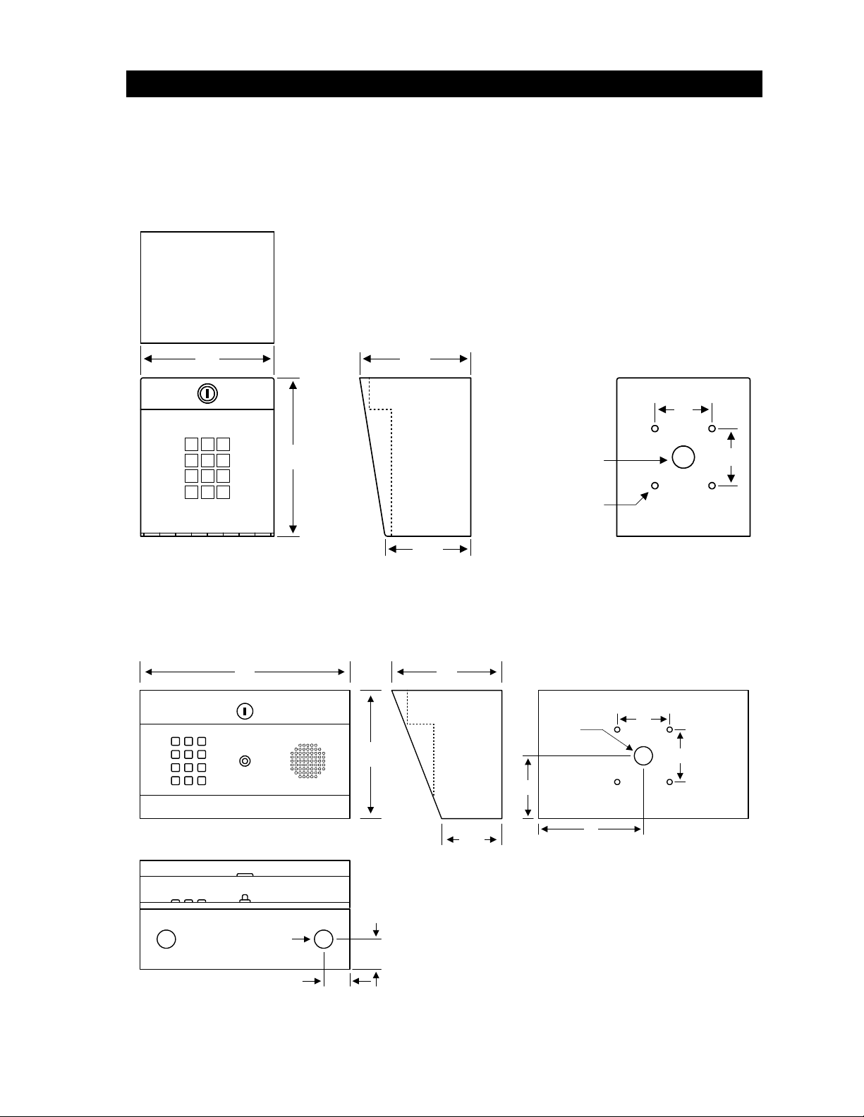
1.1 Mounting
Surface mount units can be mounted directly to a wall or pilaster, or they can be mounted using a
gooseneck mounting post (p/n 1200-045 or 1200-046).
5.25
4.375
2.5
1 2 3
654
6.25
2.5
.875
987
#0
*
.25
3.375
1506 Surface Mount
10.0 5.25
2.5
2.5
1
7 8 9
32
654
#0*
6.125
.875
3.0
2.875
.875 Dia
1.31
1.25
5.0
Model 1504 Surface Mount
1506-065-D-1-09 Page 7
Page 8
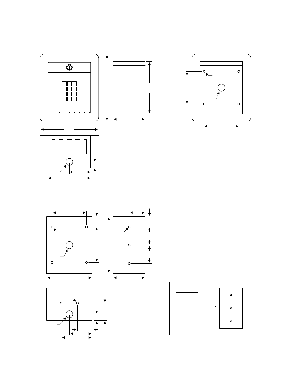
The flush mount keypad consists of two parts, the keypad and the rough-in box. Mount the rough-in
box and wiring first, and then install the keypad into the rough-in box.
.25
1 2 3
*
7.125
8.375
654
987
#0
4.0
6.625
4.375
.875
4.25
.875
.875
5.375
4.25
10-24 STUD
2.56
.75
1.25
4.375
FLUSH
MOUNT
KEYPAD
2.0
.25
7.0
2.252.251.25
4.05.625
ROUGH
.25
2.125
.75
.875
1.875
2.875
3.875
IN
BOX
ROUGH-IN BOXFLUSH KEYPAD
Page 8 1506-065-D-1-09
Page 9

1.2 Wiring
The wiring of this device is an extremely important and integral part of the access control system. It is
very important that proper wire is used for power and control lines, and that the system is properly
grounded.
• The digital keypad can operate on 10-16.5 volt AC power, or 12-24 DC power.
• The light is set to operate at 16.5 VAC power. If the keypad is to be powered from a
solar/battery system (12 VDC), we suggest that you remove the light bulb to conserve battery
power.
• Do not run power wiring greater than 200 feet.
• Do not power electric strikes or magnetic locks from the power supply. Strikes, locks and
other devices must be powered from their own power source.
• It is preferable to keep power wiring as short as possible. A low voltage surge suppresser
(P/N 1878-010) is recommended.
• Be sure to properly ground the digital keypad. Attach a separate 12 AWG wire to the ground
lug on the circuit board. Attach the other end of this wire to a good earth ground. This can
be a properly grounded metal conduit, a cold water pipe, or a grounding rod driven at least 10
feet into the soil. A gooseneck post anchored or mounted on concrete does not make a good
ground.
• Avoid any splices in wiring. If a splice is made, it must be soldered and sealed in a watertight
junction box.
• Relay contacts are rated for 30 Volt, 1 Amp.
• A switch closure across terminals 1 and 12 will activate relay 1 for its programmed strike time.
• Use U.L. listed wire with an insulation rating of 600 volts.
• If a slave keypad (p/n 1506-081) is connected, refer to the instruction sheet included with the
slave keypad assembly.
• Maximum distance for slave keypad wiring is 200 feet using an 8 conductor 22 AWG shielded
cable. An additional 2 wires are needed to power the slave keypad light.
• The slave keypad does not have any relays. It only provides a method to access the entry
codes from a second location. Typically, the slave keypad is used when both entry and exit
control are required through a common door or gate.
POWER WIRING
Wire Size Maximum Distance
18 AWG 100 Ft.
16 AWG 200 Ft.
1506-065-D-1-09 Page 9
Page 10

1.3 Wiring Diagram
1506-010
Circuit Board
GND
OFF
Master
Code
ON
16 VAC, 20 VA
Keypad Power
Magnetic
Lock
Electric Strike
Magnetic Lock
Power
Door
Switch
Electric
Strike
6 234512 11 110 9 8 714 13
Push
to Exit
Time
Zone 2
Time
Zone 1
Gate
Operator
Page 10 1506-065-D-1-09
Page 11

1.4 Circuit Board Terminal Identification
1. REQUEST TO EXIT – A switch closure to terminal 12 will activate relay 1 for its
programmed strike time.
2. DOOR OPEN – A switch closure to terminal 12 will cause the relay that is activated
to deactivate 1 second after this input is activated. Can also be used for alarm
bypass.
3. TIME ZONE 2 – A switch closure to terminal 11 will lock out all entry codes within the
time zone 2 lower and upper boundary.
4. TIME ZONE 1 – A switch closure to terminal 11 will lock out all entry codes within the
time zone 1 lower and upper boundary.
5. RELAY 1 COMMON
6. RELAY 1 NORMALLY CLOSED (N.C.)
7. RELAY 1 NORMALLY OPEN (N.O.)
8. RELAY 2 COMMON
9. RELAY 2 NORMALLY CLOSED (N.C.)
10. RELAY 2 NORMALLY OPEN (N.O.)
11. LOW VOLTAGE COMMON
12. LOW VOLTAGE COMMON
13. INPUT POWER: 10-16.5 VAC or 12-24 VDC
14. INPUT POWER: 10-16.5 VAC or 12-24 VDC
NOTES:
• A switch closure across terminals 1 and 12 will activate relay 1 for its programmed strike time.
• Relay contacts are rated for 30 Volt, 1 amp maximum power.
• The keypad unit will draw approximately 15 ma of current under stand-by condition, and
approximately 100 ma of current when the relay is activated.
• Electric strikes and magnetic locks must be powered from their own power supply as shown
on the wiring diagram (page 10). Do not power the keypad and the locking device from the
same source.
1506-065-D-1-09 Page 11
Page 12

1.5 Model 1504 Aiphone Intercom Station Connections
These wire diagrams are provided for convenience only. For detailed wiring information on Aiphone
products, visit their website at www.aiphone.com.
Speaker
Push
Button
1
Aiphone
LEF Master
Station
-
E
Red
Red
Blue
Blue
Aiphone
LEM-1
Master
Station
47 uf
+
Speaker
Push
Button
1
E
Red
Red
Blue
Blue
47 uf
+
Page 12 1506-065-D-1-09
Page 13

1.6 Secondary Keypad Wiring
8-Conductor
22 AWG
Shielded Cable
1599-010 Board
13 and 14
Terminals
To Main
To Secondary
Keypad Light
1506-081 Secondary Keypad
• Refer to Secondary Keypad Instruction Sheet (p/n 1506-066) for instructions on mounting the
1599-010 board onto the 1506-010 circuit board.
• Wire terminals 1-8 on the 1599 board to terminals 1-8 on the 1506-081 secondary keypad.
Pay careful attention to the terminal numbers as they can appear backwards (numbered right
to left) when the faceplate is opened.
• Use 22 AWG shielded cable, maximum length 200 feet.
• An additional 2 wires are needed to power the light in the secondary keypad. Connect these
wires to terminals 13 and 14 on the 1506 main terminal strip, and to the light wires in the
secondary keypad. If DC power is used to power the 1506, you may consider not connecting
the secondary light to conserve battery power.
• The secondary keypad has no relays! Valid entry codes entered on the secondary keypad
will activate the relays in the 1506 keypad.
1506-065-D-1-09 Page 13
Page 14

Page 14 1506-065-D-1-09
Page 15

SECTION 2 - PROGRAMMING
Keep a record of the programmed codes by completing the tables on pages 24 and 25.
2.1 Master Code
The Master Code is a four-digit number that is used to access all programming functions of the digital
keypad. The default factory master code is set to 9999. We suggest that you program a new master
code once the system is installed. After programming the master code, write it down and keep it in a
safe place. If you forget your master code, you will need to program a new one before you can
access any of the programming functions of the digital keypad.
1. Open the cabinet and locate the Master Code switch on the circuit board.
2. Turn the Master Code switch ON.
3. Enter a four-digit code _ _ _ _ on the keypad and then press * (short beep).
4. Turn the Master Code switch OFF and close the cabinet.
2.2 Relay Strike Time
The relay strike time sets the amount of time that the relay(s) will be activated when a valid entry
code is entered on the keypad. The unit has two relays, both of which can be programmed with
individual strike times. Setting the strike time to 00 will activate the relay for ½ second. The factory
setting is 1-second.
1. Press *03 and enter the four-digit master code _ _ _ _ (short beep).
2. Enter the relay time in seconds _ _ (00 – 99) for relay 1, then press * (short beep).
3. Enter the relay time in seconds _ _ (00 – 99) for relay 2, then press * (short beep).
4. Press 0# together to end the programming step (long beep).
2.3 X-Strikes Programming
This keypad has a 3-minute lockout feature that is activated when “X” number of invalid entry codes
are entered on the keypad. The “X” strikes can be programmed from 1 to 9 invalid tries before the
lockout feature is activated.
1. Press *04 and enter the four-digit master code _ _ _ _ (short beep).
2. Enter the number of invalid tries before the lockout feature is activated _ (1 – 9), then
press * (short beep).
3. Press 0# together to end the programming step (long beep).
1506-065-D-1-09 Page 15
Page 16

2.4 Programming Four-digit Entry Codes
1. Press *02 and enter the four-digit master code _ _ _ _ (short beep).
2. Enter the four-digit code _ _ _ _ then press * (beep).
3. Repeat step 2 to enter additional entry codes. Note: the number of codes that can be
entered is dependant on the memory size ordered.
4. Press 0# together to end the programming step (long beep).
2.5 Erasing Individual Four-digit Entry Codes
1. Press *08 and enter the four-digit master code _ _ _ _ (short beep).
2. Enter the four-digit code to be erased _ _ _ _ then press * (beep).
3. Repeat step 2 to erase additional entry codes.
4. Press 0# together to end the programming step (long beep).
2.6 Erasing ALL Four-digit Entry Codes
CAUTION: This sequence will erase ALL four-digit entry codes that have been previously
programmed into the keypad and is irreversible.
1. Press *00 and enter the four-digit master code _ _ _ _ (short beep).
2. Press 9 9 9 9 * (short beep).
3. After approximately 10-seconds, a long beep will be heard indicating that all four-digit
entry codes have been erased.
2.7 Four-digit Entry Code Divide Number
The four-digit entry codes can be made to activate either relay 1 or relay 2 by programming a fourdigit "divide" number. Four-digit entry codes equal to or less than the divide number will activate relay
1, while four-digit entry codes greater than the divide number will activate relay 2. If no divide number
is programmed (enter # # # # in step 2), then relay 2 acts as an alarm by-pass relay, activating .1
second prior to relay 1, and deactivating .1 second after relay 1.
Important: Both four-digit and five-digit entry codes must be programmed to operate in the same
mode. If a divide number is programmed for the four-digit codes, then a divide number must also be
programmed for the five-digit entry codes (see page 17). The system is preset at the factory with no
divide numbers programmed.
1. Press *12 and enter the four-digit master code _ _ _ _ (short beep).
2. Enter a four-digit divide number _ _ _ _ then press * (short beep).
3. Press 0# together to end the programming step (long beep).
Note: To delete the four-digit entry code divide number, enter # # # # in step 2. This will cause relay 2
to act as an alarm by-pass relay provided that the five-digit divide number has also been deleted (see
page 17).
Page 16 1506-065-D-1-09
Page 17

2.8 Programming Five-digit Entry Codes
1. Press *09 and enter the four-digit master code _ _ _ _ (short beep).
2. Enter the five-digit code _ _ _ _ _ then press * (beep).
3. Repeat step 2 to enter additional entry codes. Note: a maximum of 6 five-digit entry
codes can be programmed.
4. Press 0# together to end the programming step (long beep).
2.9 Erasing Individual Five-digit Entry Codes
1. Press *10 and enter the four-digit master code _ _ _ _ (short beep).
2. Enter the five-digit code to be erased _ _ _ _ _ then press * (beep).
3. Repeat step 2 to erase additional entry codes.
4. Press 0# together to end the programming step (long beep).
2.10 Erasing ALL Five-digit Entry Codes
CAUTION: This sequence will erase ALL five-digit entry codes that have been previously
programmed into the keypad and is irreversible.
1. Press *11 and enter the four-digit master code _ _ _ _ (short beep).
2. Press 9 9 9 9 * (short beep).
3. After approximately 10-seconds, a long beep will be heard indicating that all five-digit
entry codes have been erased.
2.11 Five-digit Entry Code Divide Number
The five-digit entry codes can be made to activate either relay 1 or relay 2 by programming a five-digit
"divide" number. Five-digit entry codes equal to or less than the divide number will activate relay 1,
while five-digit entry codes greater than the divide number will activate relay 2. If no divide number is
programmed (enter # # # # # in step 2), then relay 2 acts as an alarm by-pass relay, activating .1
second prior to relay 1, and deactivating .1 second after relay 1.
Important: Both four-digit and five-digit entry codes must be programmed to operate in the same
mode. If a divide number is programmed for the five-digit codes, then a divide number must also be
programmed for the four-digit entry codes (see page 16). The system is preset at the factory with no
divide numbers programmed.
1. Press *13 and enter the four-digit master code _ _ _ _ (short beep).
2. Enter a five-digit divide number _ _ _ _ _ then press * (short beep).
3. Press 0# together to end the programming step (long beep).
Note: To delete the five-digit entry code divide number, enter # # # # # in step 2. This will cause relay
2 to act as an alarm by-pass relay provided that the five-digit divide number has also been deleted
(see page 16).
1506-065-D-1-09 Page 17
Page 18

2.12 Hold Boundary Programming
The entry system hold boundaries establish a set of four-digit entry codes that will latch relay 1 ON,
relay 2 ON, or both relay 1 and relay 2 ON (depending on the divide number programmed and the
hold boundaries that have been programmed) indefinitely. To un-latch the relay(s), an entry code
within the hold boundary is entered on the keypad.
NOTE: Hold boundaries can only be established for the four-digit entry codes. Five-digit entry codes
have no hold boundaries.
1. Press *07 and enter the four-digit master code _ _ _ _ (short beep).
2. Enter a four-digit code for the lower hold boundary _ _ _ _ then press * (short beep).
3. Enter a four-digit code for the upper hold boundary _ _ _ _ then press * (short beep).
4. Press 0# together to end the programming step (long beep).
NOTE: To delete hold boundaries, enter # # # # in steps 2 and 3.
2.13 Time Zone 1 Boundary Programming
Programming the lower and upper boundaries for time zone 1 establishes a set of four-digit entry
codes that will be denied access if the time zone 1 input (terminal 3) is activated. This time zone does
not affect the five-digit entry codes.
1. Press *05 and enter the four-digit master code _ _ _ _ (short beep).
2. Enter a four-digit code for the lower boundary _ _ _ _ then press * (short beep).
3. Enter a four-digit code for the upper boundary _ _ _ _ then press * (short beep).
4. Press 0# together to end the programming step (long beep).
NOTE: To delete time zone 1 boundaries, enter # # # # in steps 2 and 3.
2.14 Time Zone 2 Boundary Programming
Programming the lower and upper boundaries for time zone 2 establishes a set of four-digit entry
codes that will be denied access if the time zone 2 input (terminal 4) is activated. This time zone does
not affect the five-digit entry codes.
1. Press *06 and enter the four-digit master code _ _ _ _ (short beep).
2. Enter a four-digit code for the lower boundary _ _ _ _ then press * (short beep).
3. Enter a four-digit code for the upper boundary _ _ _ _ then press * (short beep).
4. Press 0# together to end the programming step (long beep).
NOTE: To delete time zone 2 boundaries, enter # # # # in steps 2 and 3.
Page 18 1506-065-D-1-09
Page 19

SECTION 3 – OPERATING INSTRUCTIONS
3.1 Four-digit Entry Codes
To use a four-digit entry code, the # key must first be pressed then the four-digit code entered on the
keypad. Four-digit entry codes can be programmed to operate either relay 1 or relay 2.
When a four-digit code is entered on the keypad (preceded by #), the system checks its memory to
see if the code is stored. If the four-digit entry code is not stored in the system memory, the relay(s)
will not activate. If the four-digit code is stored, the system will then check to see if any of the time
zone inputs are activated, and if the four-digit code is within the boundaries of the time zone that is
activated. If the four-digit code falls within one or both of the time zone boundaries, the relay will not
activate. If the time zones are not activated, or if the four-digit code is outside of the activated time
zone(s), then the system will check the four-digit divide number. If the entered code is equal to or less
than the divide number, relay 1 will activate for its programmed strike time. If the entered code is
greater than the divide number, relay 2 will activate for its programmed strike time. If the door input is
activated, the relay will deactivate one second after this input is activated, regardless of the
programmed strike time. If no divide number is programmed, relay 2 will activate .1 second prior to
relay 1 activation. Relay 1 will then activate for its programmed strike time. Relay 2 will deactivate .1
second after relay 1 deactivates. If the door input (terminal 2) is activated, relay 1 will deactivate one
second after this input is activated, regardless of the relay strike time remaining. Relay 2 will stay
activated for the duration of the relay 1 strike time program.
3.2 Five-digit Entry Codes
To use a five-digit entry code, enter the five-digit code on the system keypad. Do not press # first
when using five-digit entry codes. Five-digit entry codes can be programmed to operate either relay 1
or relay 2.
When a five-digit code is entered on the keypad, the system checks its memory to see if the code is
stored. If the five-digit entry code is not stored in the system memory, the relay(s) will not activate. If
the five-digit code is stored, then the system will check the five-digit divide number. If the entered
code is equal to or less than the divide number, relay 1 will activate for its programmed strike time. If
the entered code is greater than the divide number, relay 2 will activate for its programmed strike
time. If the door input is activated, the relay will deactivate one second after this input is activated,
regardless of the programmed strike time. Five-digit entry codes are not affected by the time zone
inputs or hold boundaries.
3.3 Request to Exit Input
A switch closure across terminals 1 and 12 will cause relay 1 to activate for its programmed strike
time. This input is not affected by the time zone inputs.
3.4 Door Open Input
A switch closure across terminals 2 and 12 will cause the relay that is activated to deactivate one
second after this input is activated. A useful application of this input would be to wire it to a normally
closed door-switch that is held open when the door is closed. When the door is opened, the switch
will close, cutting off the door strike one second later. This will stop a door strike from buzzing for
prolonged periods of time if the relay strike time is set high. For example, if the relay strike time was
set for 10 seconds and the door was opened after 2 seconds, the door switch input will stop the strike
from buzzing after three seconds, even though the strike time was set to 10 seconds.
If no entry code divide number is programmed, and the second relay is being used as an alarm bypass relay, the door input switch does not prematurely deactivate the second relay. For example, if
the strike time for relay 1 is set to 10 seconds, relay 2 will activate .1 seconds prior to relay 1. If the
door input deactivates relay 1 after three seconds, relay 2 will remain activated for the full strike time.
1506-065-D-1-09 Page 19
Page 20

3.5 Hold Feature Operation
The relay hold feature allows a set of four-digit entry codes to latch (or hold) a relay indefinitely. Any
four-digit entry code that falls numerically within the hold boundaries will cause relay 1 to activate
indefinitely if no four-digit divide number is programmed. If a four-digit divide number is programmed,
and the divide number is less than the lower hold boundary, then the four-digit codes within the hold
boundary will activate relay 2. If a four-digit divide number is programmed, and the divide number is
greater than the upper hold boundary, then the four-digit codes within the hold boundary will activate
relay 1. If a four-digit divide number is programmed, and it falls between the hold boundaries, then
four-digit entry codes equal to or less than the divide number, but greater than the lower hold
boundary, will activate relay 1 indefinitely. Four-digit entry codes that are greater than the divide
number, but less than the upper hold boundary, will activate relay 2 indefinitely. Five-digit entry codes
are not affected by hold boundaries. To deactivate a relay that is latched, simply re-enter the number
that was used to activate the relay. See sample charts below.
Relay 1 Relay 2
Relay 1
momentarily
activates with
code 2000 or
lower.
Divide Number 2000
Relay 2 momentarily
activates with codes
2001 thru 2009.
Boundary 2010
Lower Hold
Relay 1 Relay 2
Relay 1
momentarily
activates with
code 2009 or
lower.
Boundary 2010
Relay 1 latches when
Lower Hold
codes 2010 thru 2015
are entered on the
keypad.
Boundary 2015
Upper Hold
Divide Number 2012
Relay 1
momentarily
activates with
code 2009 and
lower.
Relay 1 Relay 2
Boundary 2010
Relay 1 latches when
Lower Hold
codes 2010 thru 2012
are entered on
keypad.
Relay 2 latches when
codes 2010 thru 2015
are entered on the
keypad.
Relay 1 momentarily
activates with codes
2016 thru 2025
Relay 2 latches when
codes 2013 thru 2015
are entered on
keypad.
Boundary 2015
Boundary 2015
Relay 2
Upper Hold
momentarily
activates with
codes 2016 and
higher.
Divide Number 2025
Relay 2
momentarily
activates with
code 2026 or
higher.
Relay 2
Upper Hold
momentarily
activates with
code 2016 and
higher.
Page 20 1506-065-D-1-09
Page 21

3.6 Time Zone Operation
5000
3500
The entry system has two time zone inputs. By using an external timer or switch, access can be
denied to a group of four-digit entry codes during desired lockout times. Four-digit entry codes that fall
numerically within a time zone boundary will cause a check of the time zone input when the code is
entered. If time zone 1 is activated (switch closure across terminals 3 and 11), four-digit entry codes
that are within the time zone 1 boundaries will be denied access. If time zone 2 is activated (switch
closure across terminals 4 and 11), four-digit entry codes that are within time zone 2 boundaries will
be denied access. Time zone boundaries may overlap each other. Five-digit entry codes are not time
zone restricted.
Entry codes
1999 and
lower are
not time
zone
restricted.
Entry codes
1999 and
lower are
not affected
by time
zones.
Lower Boundary
2000
TZ 1 Lower Boundary
2000
Upper Boundary
TZ 2 Lower Boundary
Entry codes
3001 thru
3999 are not
time zone
restricted.
Entry codes
2500 thru
2999 are
restricted bt
TZ 1 and TZ
2.
Lower Boundary
4000
TZ 1 Upper Boundary
3000
Entry codes 4000
thru 5000 are
restricted by time
zone 2.
Entry codes
3000 thru 3500
are restricted by
TZ 2 only.
Time Zone 1 Time Zone 2
Entry codes 2000
thru 3000 are
restricted by time
zone 1.
3000
Time Zone 1
Entry codes
2000 thru 2499
are restricted by
TZ 1 only.
2500
Time Zone 2
Upper Boundary
TZ 2 Upper Boundary
Entry
codes
5001 and
higher are
not time
zone
restricted.
Entry
codes
3501 and
higher are
not time
zone
restricted.
1506-065-D-1-09 Page 21
Page 22

Page 22 1506-065-D-1-09
Page 23

SECTION 4 - APPENDIX
4.1 Troubleshooting
• Have a good VOM meter to use when checking voltages and continuity.
• Check power wiring wire size and distance. Improper wire size and too long wire run
distances can cause problems.
• Check that the power transformer is rated at 16.5 VAC, 20 VA minimum.
SYMPTON POSSIBLE SOLUTION(S)
Cannot get into the
programming mode.
Keypad emits a long tone and
cancels the programming mode.
System is dead. Check for 16 VAC at terminals 13 and 14.
Four-digit entry codes will not
activate relay 1.
Four-digit entry codes will not
activate relay 2.
Five-digit entry codes will not
activate relay 1.
Five-digit entry code will not
activate relay 2.
Relay(s) lock on for long periods
of time.
Request to exit input will not
operate relay.
Wrong master code entered. Start over.
Waiting too long when entering data. Enter information quickly.
Keypad may not be plugged in correctly. Unplug and reconnect.
Waiting too long between pushing buttons while programming.
Memory is filled. Delete some codes or erase entire memory.
Forgetting to press * first.
Keypad may not be plugged in correctly. Unplug and reconnect.
X strikes feature may be activated. Wait 3 minutes and try again.
Be sure entry code is programmed into the keypad.
Press # first, then enter four-digit number.
Code may be time zone restricted. Reprogram time zone or disable time zone input.
Be sure entry code is less than divide number or reprogram divide number.
Be sure entry code is programmed into the keypad.
Press # first, then enter four-digit number.
Code may be time zone restricted. Reprogram time zone or disable time zone input.
Be sure entry code is greater than divide number or reprogram divide number.
Be sure entry code is programmed into the keypad.
Enter five-digit code directly on keypad. Do not press # first.
Be sure entry code is less than divide number or reprogram divide number.
Be sure entry code is programmed into the keypad.
Enter five-digit code directly on keypad. Do not press # first.
Be sure entry code is greater than divide number or reprogram divide number.
Excessive voltage-drop on power wires. Check transformer and wire size.
Transformer has too low VA rating.
Relay hold feature may be activated. Reprogram hold boundaries.
Relay strike time may be programmed too long. Reprogram.
Check wiring connected to terminals 1 and 12.
1506-065-D-1-09 Page 23
Page 24

4.2 Data Tables
Use the tables below to record data entered into the keypad system.
MASTER CODE
4-DIGIT HOLD BOUNDARIES
LOWER
UPPER
4-DIGIT DIVIDE NUMBER
TIME ZONE 1 BOUNDARIES
LOWER
UPPER
TIME ZONE 2 BOUNDARIES
LOWER
UPPER
5-DIGIT ENTRY CODES
1
2
3
4
5
6
5-DIGIT DIVIDE NUMBER
Page 24 1506-065-D-1-09
Page 25

NAME 4-DIGIT
CODE
NAME 4-DIGIT
CODE
1506-065-D-1-09 Page 25
 Loading...