

Page 1
EC DECLARATION OF CONFORMITY FOR MACHINES
(DIRECTIVE 98/37/EC)
Manufacturer: FAAC S.p.A.
Address: Via Benini, 1 - 40069 Zola Predosa BOLOGNA - ITALY
Declares that: 740-24V mod. operator
• is built to be integrated into a machine or to be assembled with other machinery to create a machine under the
provisions of Directive 98/37/EC;
• conforms to the essential safety requirements of the following EEC directives:
73/23/EEC and subsequent amendment 93/68/EEC.
89/336/EEC and subsequent amendment 92/31/EEC and 93/68/EEC
and also declares that it is prohibited to put into service the machinery until the machine in which it will be
integrated or of which it will become a component has been identified and declared as conforming to the
conditions of Directive 98/37/EC.
Bologna, 01 January 2004
The Managing Director
A. Bassi
WARNINGS FOR THE INSTALLER
GENERAL SAFETY OBLIGATIONS
1) ATTENTION! To ensure the safety of people, it is important that you
read all the following instructions. Incorrect installation or incorrect
use of the product could cause serious harm to people.
2) Carefully read the instructions before beginning to install the product.
3) Do not leave packing materials (plastic, polystyrene, etc.) within reach
of children as such materials are potential sources of danger.
4) Store these instructions for future reference.
5) This product was designed and built strictly for the use indicated in this
documentation. Any other use, not expressly indicated here, could
compromise the good condition/operation of the product and/or be
a source of danger.
6) FAAC declines all liability caused by improper use or use other than that
for which the automated system was intended.
7) Do not install the equipment in an explosive atmosphere: the presence
of inflammable gas or fumes is a serious danger to safety.
8) The mechanical parts must conform to the provisions of Standards EN
12604 and EN 12605.
For non-EU countries, to obtain an adequate level of safety, the
Standards mentioned above must be observed, in addition to national
legal regulations.
9) FAAC is not responsible for failure to observe Good Technique in the
construction of the closing elements to be motorised, or for any
deformation that may occur during use.
10) The installation must conform to Standards EN 12453 and EN 12445.
For non-EU countries, to obtain an adequate level of safety, the
Standards mentioned above must be observed, in addition to national
legal regulations.
11) Before attempting any job on the system, cut out electrical power .
12) The mains power supply of the automated system must be fitted with
an all-pole switch with contact opening distance of 3mm or greater.
Use of a 6A thermal breaker with all-pole circuit break is recommended.
13) Make sure that a differential switch with threshold of 0.03 A is fitted
upstream of the system.
14) Make sure that the earthing system is perfectly constructed, and
connect metal parts of the means of the closure to it.
15) The automated system is supplied with an intrinsic anti-crushing safety
device consisting of a torque control. Nevertheless, its tripping
threshold must be checked as specified in the Standards indicated
at point 10.
16) The safety devices (EN 12978 standard) protect any danger areas
against mechanical movement Risks, such as crushing, dragging,
and shearing.
17) Use of at least one indicator-light (e.g. FAACLIGHT ) is recommended
for every system, as well as a warning sign adequately secured to the
frame structure, in addition to the devices mentioned at point “16”.
18) FAAC declines all liability as concerns safety and efficient operation
of the automated system, if system components not produced by
FAAC are used.
19) For maintenance, strictly use original parts by FAAC.
20) Do not in any way modify the components of the automated system.
21) The installer shall supply all information concerning manual operation
of the system in case of an emergency, and shall hand over to the
user the warnings handbook supplied with the product.
22) Do not allow children or adults to stay near the product while it is
operating.
23) Keep remote controls or other pulse generators away from children,
to prevent the automated system from being activated involuntarily.
24)
Transit is permitted only when the automated system is idle.
25) The user must not attempt any kind of repair or direct action whatever
and contact qualified personnel only.
26) Maintenance: check at least every 6 months the efficiency of the
system, particularly the efficiency of the safety devices (including,
where foreseen, the operator thrust force) and of the release
devices.
27 ) Anything not expressly specified in these instructions is not permitted.
6
Page 2
AUTOMATED SYSTEM 740-24V
These instructions apply to the following models:
The 740 gearmotor is an electro-mechanical operator designed for moving sliding
gates.
The non-reversing reduction system ensures the gate is mechanically locked
when the gearmotor is not operating, therefore it is not necessary to install any
electric lock
740 24V
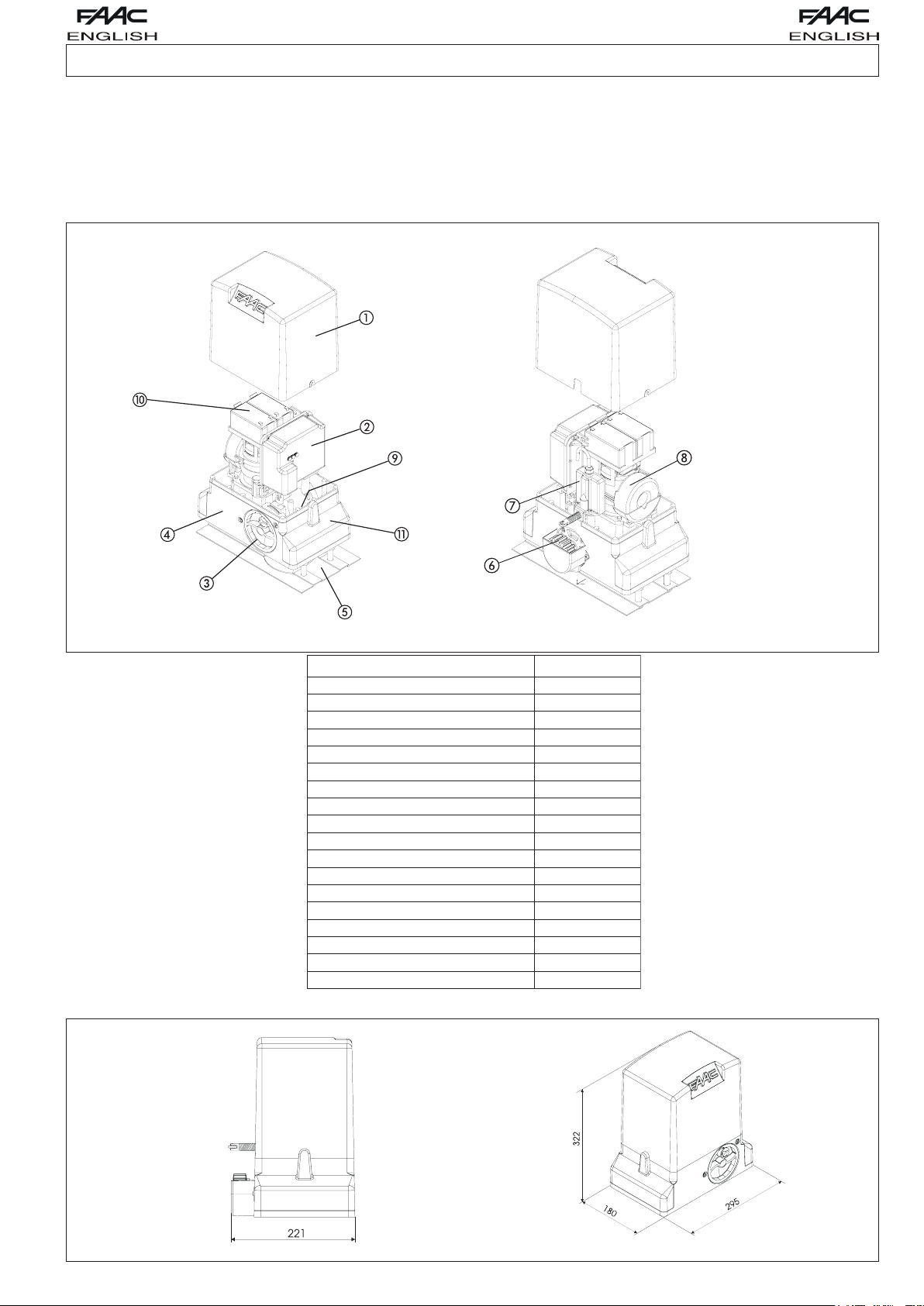
1. DESCRIPTION AND TECHNICAL SPECIFICATIONS
A convenient manual release with customised key makes it possible to move the
gate in the event of a power failure or malfunction of the operator.
The 740 gearmotor was designed and built for controlling vehicle access. AVOID
ANY OTHER USE WHATEVER.
1. Motor lid
2. Electronic control unit
3. Release device
4. Gearmotor body
5. Foundation plate
6. Pinion
7. Limit switch
8. Transformer
9. Cable holes
10. Battery (optional)
11. Protective side panels
Values are expressed in mm
LEDOMV42-047
ylppusrewoP
)W(rewopdebrosbA
)A(tnerrucdebrosbA
)Fµ(roticapaC
otsurhT
aG
hctulC
repO
)Nad(noinipn
)mN(euqroT
)C°(noitcetorplamrehtgnidniW
)gK(thgiewxamfaeL
noinipfoepyT
)nim/m(deepset
)m(htgnelxametaG
hctiwstimilfoepyT
ycneuqerfesU
)C°(erutarepmetgnita
)gK(thgiewrotomraeG
ssalcnoitcetorP
snoisnemidllarevorotomraeG
2. DIMENSIONS
Fig.01
zH06/05~V511/032
07
3
-
04
5.31
-
004
61Z
21
51
lacinahceM
cinortcelE
%001
55+02-
5.8
44PI
20.giFeeS
Fig.02
7
Page 3

3. MAXIMUM USE CURVE
The curve makes it possible to establish
maximum work time (T) according to use
frequency (F).
With reference to IEC 34-1 Standard, the
740 gearmotor with an S3 duty, can operate at a use frequency of 100%.
To ensure efficient operation, it is
necessary to operate in the work range
below the curve.
Important: The curve is obtained at a
temperature of 20°C. Exposure to
the direct sun rays can reduce use
frequency down to 20%.
Calculation of use frequency
Use frequency is the percentage of
effective work time (opening + closing)
compared to total time of cycle (opening
+ closing + pause times).
Calculation formula:
Values are expressed in mm
Fig.05
% F =
where:
Ta = opening time
Tc = closing time
Tp = pause time
Ti = time of interval between two complete cycles
Ta + Tc
Ta + Tc + Tp + Ti
X 100
4. ELECTRICAL SET-UP (standard system)
1- Operator with unit
2- Photocells
3- Key-operated push button
4- Flashing lamp
5- Radio receiver
Fig.03
5. INSTALLING THE AUTOMATED SYSTEM
5.1. Preliminary checks
To ensure safety and efficiency of the automated system, make sure the following
requirements are observed before installing the system:
• The gate structure must be suitable for automation. The following are necessary
in particular: wheel diameter must be in proportion to the weight of the gate,
an upper track must be provided, plus mechanical travel stops to prevent
the gate derailing.
• The soil must guarantee a perfect stability of the foundation plinth.
• There must be no pipes or electric cables in the plinth excavation area.
• If the gearmotor is located in the vehicle transit or manoeuvre area, adequate
means of protection should be provided against accidental impact.
• Check if an efficient earthing is available for connection to the gearmotor.
5.2. Masonry for foundation plate
1- Assemble the foundation plate as shown in figure 04.
2- In order to ensure that the pinion and rack engage correctly, the foundation
plate must be positioned as shown
in Fig. 05 (right closing) or Fig. 06 (left
closing).
Values are expressed in mm
Values are expressed in mm
3- After determining the position of the foundation plate, make a plinth as shown
in Fig. 07 and wall the plate, providing several sheaths for routing the cables.
Using a spirit level, check if the plate is perfectly level. Wait for the cement to
set.
4- Lay the electric cables for connection to the accessories and power supply
as shown in diagram of Fig. 03. To facilitate connections to the control unit,
Values are expressed in mm
allow the cables to protrude by at least 50 cm from the hole on the foundation
plate.
Fig.06
Fig.07
5.3. Mechanical installation
1- Remove the cover, Fig. 08 ref. 1.
2- Position the operator on the foundation
plate, using the supplied washers and nuts
as shown in Fig. 09. During this operation,
route the cables through the appropriate
openings in the motor body (See Fig.01
ref.9). If necessary, the two holes can be
joined using a hammer to obtain a wider
space.
3- Adjust the height of the gearmotor and
the distance from the gate, referring to
dimensions in Fig. 10.
Attention: This operation is necessary to
ensure the rack is correctly secured and
to enable any new adjustments.
Fig.08
Fig.04
Warning: The arrow on the foundation plate must always point to the gate,
see Figs. 05-06.
Fig.09
8
Page 4

Values are expressed in mm
4- Secure the gearmotor to the plate, tightening the nuts.
5- Prepare the operator for manual operation as described in paragraph 8.
Fig.10
5.4. Assembling the rack
5.4.1. Steel rack to weld (Fig. 11)
1) Fit the three threaded pawls on the rack element, positioning them at the
bottom of the slot. In this way, the slot play will enable any future adjustments
to be made.
2) Manually take the leaf into its closing
position.
3) Lay the first section of rack level on the
pinion and weld the threaded pawl on
the gate as shown in Fig. 13.
4) Move the gate manually, checking if
the rack is resting on the pinion, and
weld the second and third pawl.
5) Position another rack element end to
end with the previous one, using a
section of rack (as shown in Fig. 14) to
synchronise the teeth of the two elements.
6) Move the gate manually and weld the three threaded pawls, thus
proceeding until the gate is fully covered.
Fig.11
5.4.2. Steel rack to screw (Fig. 12)
1) Manually take the leaf into its closing position.
2) Lay the first section of rack level on the pinion and place the spacer between
the rack and the gate, positioning it at the bottom of the slot.
3) Mark the drilling point on the gate. Drill a Ø 6,5 mm hole and thread with an
M8 male tap. Screw the bolt.
4) Move the gate manually, checking if
the rack is resting on the pinion, and
repeat the operations at point 3.
5) Position another rack element end to
end with the previous one, using a
section of rack (as shown in figure 14) to
synchronise the teeth of the two
elements.
6) Move the gate manually and carry
out the securing operations as for the
first element, thus proceeding until the
gate is fully covered.
Fig.12
Notes on rack installation
• Make sure that, during the gate travel, all
the rack elements do not exit the pinion.
• Do not, on any account, weld the rack
elements either to the spacers or to each
other.
• When the rack has been installed, to ensure
it meshes correctly with the pinion, it is
advisable to lower the gearmotor position
by about 1.5 mm (Fig.15).
• Manually check if the gate correctly
reaches the mechanical limit stops
maintaining the pinion and rack coupled
and make sure there is no friction during
gate travel.
• Do not use grease or other lubricants
between rack and pinion.
mm
Values are expressed in
Fig.15
6. START-UP
6.1. Control board connection
Before attempting any work on the board (connections, programming,
maintenance), always turn off power.
Follow points 10, 11, 12, 13 and14 of the GENERAL SAFETY OBLIGATIONS.
Following the instructions in Fig. 3, route the cables through the raceways and
make the necessary electric connections to the selected accessories.
Always separate power cables from control and safety cables (push-button,
receiver, photocells, etc.). To avoid any electric noise whatever, use separate
sheaths.
6.1.1. Earthing
Connect the earth cables as shown in Fig.16 ref.A.
6.1.2. Electronic control unit
In the gearmotors, the electronic control unit is fitted to an adjustable support
(Fig. 16 ref. 1) with transparent lid (Fig. 16 ref. 3).
The board programming push buttons (Fig. 16 ref. 4) have been located on the
lid. This allow the board to be programmed without removing the lid.
For correct connection of the control unit, follow indications the specific instructions:
Fig.13
Fig.14
6.1.3. Connection of power cable
The 740-24V gearmotor houses a screw terminal with fuse-holder (Fig 17 Ref. A)
connected to the primary circuit of the toroidal transformer. The mains power
cable 230 / 115 V ~ must be connected to this terminal, respecting what was specified
in Fig. 17. If you have to replace the fuse, use a fuse type T1.6A/250V - 5x20 for a
230V power supply and type T3.15A/250V - 5x20 for a 115V power supply.
9
Fig.16
Fig.17
Page 5

6.2. Positioning the limit switches
The operator has a mechanical travel stop with spring-lever, which commands
gate movement to stop when a profiled steel plate, secured on the top of the
rack, activates the spring until the microswitch is tripped. The plate support can be
fitted to all racks with max. width of 13 mm.
Procedure for correct positioning of the two travel stop
plates supplied:
1) Fit and secure the 2 profiled steel plates on the 2 Usupports, using the supplied nuts and washers, as shown in
figure 18.
2) Prepare the operator for manual operation as
described in paragraph 8.
3) Power up the system.
4) Securing the opening limit switch: manually take the
gate to opening position, leaving 20 mm from the
mechanical travel stop.
5) Allow the plate to slide over the rack in opening direction (Fig.19). As soon as
the opening limit switch LED on the control board goes off, take the plate
forward by about 20÷30 mm and secure it provisionally on the rack, using the
supplied screws.
Fig.18
travel stops.
10) Appropriately adjust the position of the travel stop plates and definitively
secure them on the rack.
7. TESTING THE AUTOMATED SYSTEM
After installing the operator, carefully check operating efficiency of all accessories
and safety devices connected to it.
Return the board support to its original position. Fit the cover, Fig. 25 ref. 1, and tighten
the two side screws provided (Fig. 26 ref 2), and snap-fit the side panels (Fig. 26 ref.3).
Apply the danger sticker on the top of the cover (Fig. 27).
Hand the “User’s Guide” to the Customer and explain correct operation and use
of the gearmotor, indicating the potentially dangerous areas of the automated
Fig.19
6) Repeat the operations at points 4 and 5 for the closing limit switch, Fig. 20.
Important:
a) The plate must activate the limit-switch on the profiled part as shown in figure
21.
b) If the wheel and the travel stop plate are too close, it may be necessary to
shorten the limit-switch spring by a couple of turns. Procedure for shortening the
spring:
- To remove the spring, turn it clockwise. This operation requires some force.
- Shorten the spring as shown in Fig. 23: two turns correspond to about 3 mm.
- Fit the spring turning it clockwise, Fig. 24, until the stop is reached; see Fig. 25.
- Once the spring is back in place, ensure the wheel is horizontal. A wrong wheel
orientation may jeopardise the operation of the limit switches.
Fig.20
Fig.21
Fig.26
system.
Fig.27
8. MANUAL OPERATION
Warning: Cut power to the system to prevent an involuntary pulse from
activating the gate during the release manoeuvre.
To release the operator proceed as follows:
1) Insert the key provided and turn it clockwise as shown in Fig. 28 ref. 1 and 2.
2) Turn the release system clockwise, until the mechanical stop is reached, Fig. 28
ref. 3.
Fig.28
3) Open and close the gate manually.
9. RESTORING NORMAL OPERATION
Warning: Cut power to the system to prevent an involuntary pulse from
activating the gate during the manoeuvre for restoring normal operation.
To restore normal operation proceed as follows:
1) Turn the release system anti-clockwise, until its stop is reached, Fig. 29 ref. 1.
2) Turn the key anti-clockwise and remove it from the lock, Fig. 29 ref. 2 and 3.
3) Move the gate until the release system meshes (corresponds to gate locking)
Fig.22 Fig.23
Values are expressed in mm
Fig.24
8) Re-lock the system (see paragraph 9).
Important: Before sending a pulse, make sure that the gate cannot be moved
manually.
9) Command a complete gate cycle to check if the limit switch is tripped
correctly.
Warning: To avoid damaging the operator and/or interrupting operation of
the automated system, allow a space of about 20 mm from the mechanical
Fig.25
4) Power up the system.
10. SPECIAL APPLICATIONS
There are no special applications.
11. MAINTENANCE
Check the operational efficiency of the system at least once every 6 months,
especially as regards the efficiency of the safety and release devices (including
operator thrust force).
12. REPAIRS
For any repairs, contact the authorised Repair Centres.
10
Fig.29
Page 6

User’s guide
740 - 24V
Fig. 01
ENGLISH
AUTOMATED SYSTEM 740-24V
Read the instructions carefully before using the product and keep them for
future consultation.
GENERAL SAFETY RULES
If installed and used correctly, the 740-24V automated system will ensure a high
degree of safety.
Some simple rules regarding behaviour will avoid any accidental trouble:
• Do not stand near the automated system and do not allow children and
other people or things to stand there, especially while it is operating.
• Keep radiocontrols or any other pulse generator well away from children to
prevent the automated system from being activated involuntarily.
• Do not allow children to play with the automated system.
• Do not willingly obstruct gate movement.
• Prevent any branches or shrubs from interfering with gate movement.
• Keep light signalling systems efficient and clearly visible.
• Do not attempt to activate the gate by hand unless you have released it.
• In the event of malfunctions, release the gate to allow access and wait for
qualified technical personnel to do the necessary work.
• After enabling manual operation, switch off the power supply to the system
before restoring normal operation.
• Do not make any alterations to the components of the automated system.
• Do not attempt any kind of repair of direct action whatsoever and contact
qualified personnel only.
• Call in qualified personnel at least every 6 months to check the efficiency of
the automated system, safety devices and earth connection.
DESCRIPTION
The 740-24V automated system is ideal for controlling vehicle access areas of
medium transit frequency.
The 740-24V automated system for sliding gates is an electro-mechanical operator
transmitting motion to the sliding gate via a rack pinion or chain appropriately
coupled to the gate.
Operation of the sliding gate is controlled by an electronic control unit housed
inside the operator or in a hermetically sealed outdoor enclosure.
When, with the gate closed, the unit receives an opening command by
radiocontrol or from another suitable device, it activates the motor until the
opening position is reached.
If automatic operation was set, the gate re-closes automatically after the selected
pause time has elapsed.
If the semi-automatic operation was set, a second pulse must be sent to close
the gate again.
An opening pulse during re-closing, always causes movement to be reversed.
A stop pulse (if provided) always stops movement.
The light signalling indicates that the gate is currently moving.
For details on sliding gate behaviour in different function logics, consult the
installation technician.
The automated systems include obstacle-detection and/or safety devices
(photocells, edges) that prevent the gate from closing when there is an obstacle
in the area they protect.
The system ensures mechanical locking when the motor is not operating and,
therefore, it is not necessary to install any lock.
Manual opening is, therefore, only possible by using the release system.
The gearmotor does not have a mechanical clutch and, therefore, it is coupled
to a unit with an electronic clutch offering the necessary anti-crushing safety if
the system is completed with the necessary safety devices.
A convenient manual release with customised key makes it possible to move the
gate in the event of a power failure or malfunction.
MANUAL OPERATION
Fig. 02
Warning: Cut power to the system to prevent an involuntary pulse from
activating the gate during the release manoeuvre
To release the operator proceed as follows:
1) Insert the key provided and turn it clockwise as shown in Fig. 01 ref. 1 and 2.
2) Turn the release system clockwise, until the mechanical stop is reached, Fig.
01 ref. 3.
3) Open and close the gate manually.
RESTORING NORMAL OPERATION
Warning: Cut power to the system to prevent an involuntary pulse from
activating the gate during the manoeuvre for restoring normal operation.
To restore normal operation proceed as follows:
1) Turn the release system anti-clockwise, until its stop is reached, Fig. 02 ref. 1.
2) Turn the key anti-clockwise and remove it from the lock, Fig. 02 ref. 2 and 3.
3) Move the gate until the release system meshes (corresponds to gate locking).
4) Power up the system.
MAINTENANCE
To ensure trouble-free operation and a constant safety level, an overall check of
the system should be carried out every 6 months. A form for recording routine
maintenance operations is enclosed.
REPAIRS
For any repairs, contact the authorised Repair Centres.
AVAILABLE ACCESSORIES
Refer to catalogue for available accessories.
11
 Loading...