

Page 1
S800H
24V Underground Hydraulic Swing Gate Operator
FAAC International Inc.
Headquarter & East Coast Operations
5151 Sunbeam Road
Suites 9-11
Jacksonville, FL 32257
Tel. 866 925 3222
www.faacusa.com
UL325 - UL991
FAAC International Inc.
West Coast Operations
357 South Acacia Avenue
Unit 357
Fullerton, CA 92831
Tel. 800 221 8278
1
Page 2
CONTENTS
IMPORTANT SAFETY INFORMATION 3
Important Safety Instructions 3
Important Installation Instructions 3
General Safety Precautions 4
UL325 Gate Operator Classications 5
Installing the Warning Signs 5
1. DESCRIPTION AND CHARACTERISTICS 6
1.1 TECHNICAL SPECIFICATIONS 6
1.2 ELECTRICAL LAYOUT 6
2. INSTALL THE LOAD BEARING BOX 7
3. INSTALL THE OPERATOR 9
3.1 INTERNAL MECHANICAL POSITIVE STOPS 11
3.2 ADJUSTMENT OF THE TRAVEL-LIMIT STOPS 11
3.3 FINAL STEPS 11
4. MANUAL OPERATIONS 12
4.1 BUILT IN HYDRAULIC RELEASE 12
4.2 EXTERNAL IN HYDRAULIC RELEASE 12
5. MAINTENANCE 13
5.1 BLEEDING OPERATIONS 13
7.2 MECHANICAL EMERGENCY RELEASE 13
6. ENCODER CONNECTION 14
7. S800H PARTS DIAGRAM 16
E024U CONTROL BOARD AND LIMITED WARRANTY A2 - A18
Read this instruction manual before you begin installing the product.
= Information regarding personal safety and proper maintanence of the product.
FAAC Model S800H - Rev: 02 - JUN 2012
2
FAAC Model S800H Swing Gate Operator
Page 3

IMPORTANT SAFETY INFORMATION
Important Safety Instructions
WARNING - TO REDUCE THE RISK OF SEVERE
INJURY OR DEATH:
• READ AND FOLLOW ALL INSTRUCTIONS.
• Never let children operate or play with the gate
controls. Keep remote controls away from children.
• Always keep people and objects away from the
gate. NO ONE SHOULD CROSS THE PATH OF A
MOVING GATE.
• Test the gate operator monthly. The gate MUST
reverse on contact with a rigid object or when an
object activates a non-contact sensor. If necessary,
adjust the force or the limit of travel and then retest
the gate operator. Failure to properly adjust and retest
the gate operator can increase the risk of injury or
death.
• Use the manual release mechanism only when the
gate is not moving.
• KEEP GATE PROPERLY MAINTAINED. Have
a qualied service person make repairs to gate
hardware.
• The entrance is for vehicles only. Pedestrians must
use a separate entrance.
• SAVE THESE INSTRUCTIONS.
Important Installation Instructions
1. Install the gate operator only when the following
conditions have been met:
• The operator is appropriate for the type and usage
class of the gate.
• All openings of a horizontal slide gate have been
guarded or screened from the bottom of the gate to
a minimum of 4 feet (1.25 m) above the ground to
prevent a 2.25 inch (55 mm) diameter sphere from
passing through openings anywhere in the gate or
through that portion of the adjacent fence that the
gate covers when in the open position.
• All exposed pinch points are eliminated or guarded.
• Guarding is supplied for exposed rollers.
2. The operator is intended for installation on gates used
by vehicles only. Pedestrians must be provided with a
separate access opening.
3. To reduce the risk of entrapment when opening and
closing, the gate must be installed in a location that
allows adequate clearance between the gate and
adjacent structures. Swinging gates shall not open
outward into public access areas.
4. Before installing the gate operator, ensure that the gate
has been properly installed and that it swings freely in
both directions. Do not over-tighten the operator clutch
or pressure relief valve to compensate for a damaged
gate.
5. User controls must be installed at least 6 feet (1.83
m) away from any moving part of the gate and located
where the user is prevented from reaching over, under,
around or through the gate to operate the controls.
Controls located outdoors or those that are easily
accessible shall have security features to prevent
unauthorized use.
6. The Stop and/or Reset buttons must be located within
line-of-sight of the gate. Activation of the reset control
shall not cause the operator to start.
7. All warning signs and placards must be installed
and easily seen within visible proximity of the gate. A
minimum of one warning sign shall be installed on each
side of the gate.
8. For gate operators that utilize a non-contact sensor
(photo beam or the like):
• See instructions on the placement of non-contact
sensors for each type of application.
• Exercise care to reduce the risk of nuisance tripping,
such as when a vehicle trips the sensor while the
gate is still moving.
• Locate one or more non-contact sensors where the
risk of entrapment or obstruction exists, such as at
the reachable perimeter of a moving gate or barrier.
• Use only FAAC “Photobeam” photoelectric eyes to
comply with UL325.
FAAC Model S800H Swing Gate Operator
3
Page 4

Important Installation Instructions (continued)
General Safety Precautions
9. For gate operators that utilize a contact sensor (edge
sensor or similar):
• Locate one or more contact sensors where the risk
of entrapment or obstruction exists, such as at the
leading edge, trailing edge, and post mounted both
inside and outside of a vehicular horizontal slide
gate
• Locate one or more contact sensors at the bottom
edge of a vehicular vertical lift gate.
• Locate one or more contact sensors at the bottom
edge of a vertical barrier (arm).
• Locate one or more contact sensors at the pinch
point of a vehicular vertical pivot gate.
• Locate hard-wired contact sensors and wiring so
that communication between sensor and gate
operator is not subjected to mechanical damage.
• Locate wireless contact sensors, such as those
that transmit radio frequency (RF) signals, where
the transmission of signals are not obstructed or
impeded by building structures, natural landscaping
or similar hindrances. Wireless contact sensors shall
function under their intended end-use conditions.
• Use only FAAC MSE MO, CN60 or M60 edge
sensors.
Gate Construction
Vehicular gates should be constructed and installed
in accordance with ASTM F2200: Standard Specication for Automated Vehicular Gate Construction.
For more information, contact ASTM at: www.astm.org
Installation
• If you have any questions or concerns regarding the
safety of the gate operating system, do not install the
operator and consult the manufacturer.
• The condition of the gate structure itself directly
affects the reliability and safety of the gate operator.
• Only qualied personnel should install this equipment.
Failure to meet this requirement could cause severe
injury and/or death, for which the manufacturer
cannot be held responsible.
• The installer must provide a main power switch that
meets all applicable safety regulations.
• It is extremely unsafe to compensate for a damaged
gate by increasing hydraulic pressure.
• Install devices such as reversing edges and photo
beams to provide better protection for personal
property and pedestrians. Install reversing devices
that are appropriate to the gate design and
application.
• Before applying electrical power, ensure that voltage
requirements of the equipment correspond to the
supply voltage. Refer to the label on your gate
operator system.
Usage
• Use this equipment only in the capacity for which it
was designed. Any use other than that stated should
be considered improper and therefore dangerous.
• The manufacturer cannot be held responsible
for damage caused by improper, erroneous or
unreasonable use.
• If a gate system component malfunctions, disconnect
the main power before attempting to repair it.
• Do not impede the movement of the gate, you may
injure yourself or damage the gate system as a result.
• This equipment may reach high thermal temperatures
during normal operation, therefore use caution when
touching the external housing of the gate operator.
• Use the manual release mechanism according to the
procedures presented in this manual.
• Before performing any cleaning or maintenance
operations, disconnect power to the equipment.
• All cleaning, maintenance or repair work must
performed by qualied personnel.
4
FAAC Model S800H Swing Gate Operator
Page 5
UL325 Gate Operator Classications
RESIDENTIAL VEHICULAR GATE OPERATOR CLASS I
A vehicular gate operator system intended for use in a single family dwelling, garage or associated parking area.
COMMERCIAL / GENERAL ACCESS VEHICULAR GATE OPERATOR CLASS II
A vehicular gate operator system intended for use in commercial locations or buildings such as multi-family housing
units (ve or more single family units), hotels, parking garages, retail stores or other buildings that service the general
public.
INDUSTRIAL / LIMITED ACCESS VEHICULAR GATE OPERATOR CLASS III
A vehicular gate operator system intended for use in industrial locations or buildings such as factories, loading docks
or other locations not intended to service the general public.
RESTRICTED ACCESS VEHICULAR GATE OPERATOR CLASS IV
A vehicular gate operator system intended for use in guarded industrial locations or buildings such as airport security
areas or other restricted access locations that do not service the general public, and in which unauthorized access is
prevented via supervision by security personnel.
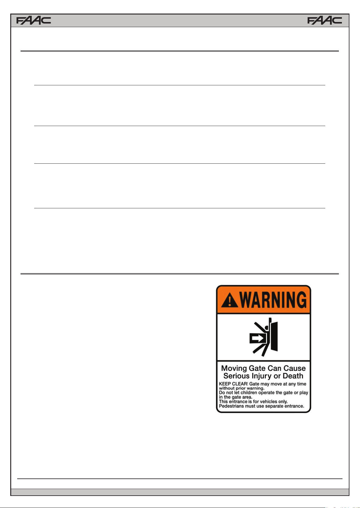
Installing the Warning Signs
This FAAC swing gate operator is supplied
with two warning signs to alert people that a
possible hazard exists and that appropriate
actions should be taken to avoid the hazard or
to reduce exposure to it.
Permanently install one warning sign on each
side of the gate so they are fully visible to
trafc and pedestrians.
Use appropriate hardware such as metal
screws (not supplied) to permanently install
each warning sign.
FAAC Model S800H Swing Gate Operator
5
Page 6
Model S800H 24V Underground Hydraulic Swing Gate Operator
1. DESCRIPTION AND CHARACTERISTICS
FAAC S800H is an integrated hydraulic automated system, permitting vehicle access through swing leaf gates which, when in-when installed invisibly in the ground, does not alter the appearance of the gate. The model with a hydraulic lock device (CBAC) does not
require the installation of an electrical lock, as it guarantees the mechanical locking of the leaf when the motor is not operating. The
model without a hydraulic lock device always requires one or more electrical locks to ensure the leaf is mechanically locked. The
S800H automated systems were designed and built to automate swing leaf gates. Do not use for any other purpose.
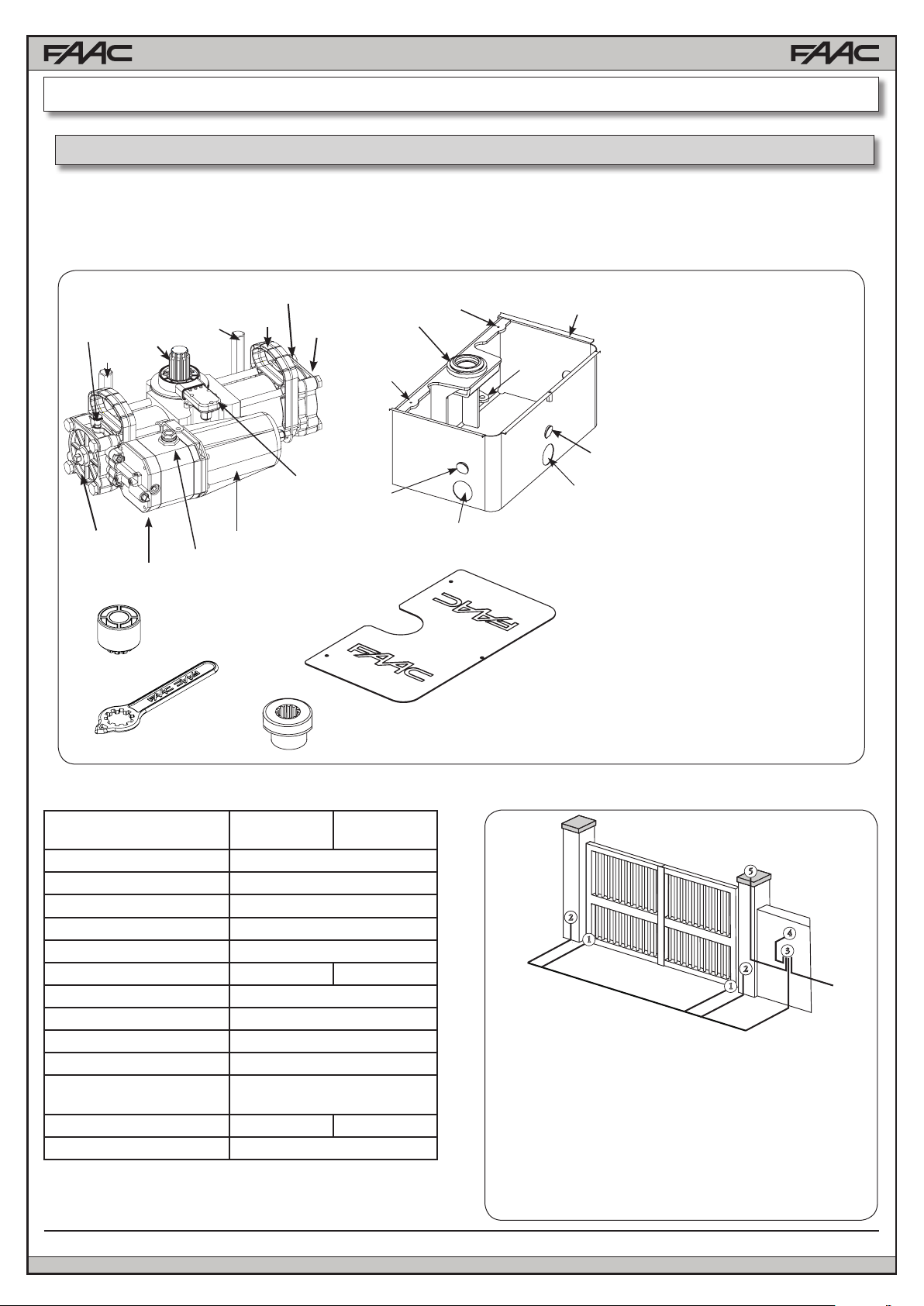
1
2
1
3
4
5
4
11
13
11
12
11
10
1 Bleed screw
2 Support handle
3 Pinion
4 Securing screws
5 Screw for adjusting travel-limit
mechanical stops
6 Hydraulic release
16
9
14
17
7 Oil lling plug
8 Motor
9 Electronic encoder
10 Bearing case
11 Holes for securing the cover
5
6
8
14
7
15
17
12 Slots for securing the jack
13 Bearing bush
14 Wings for walling the
bearing case.
15 Hole for power cable or
drain pipe
16 Plastic adjustment wrench
and support bushing
17 Foundation box cover
16
18 Grooved bushing (p/n 390972)
18
Fig.1
1.1 TECHNICAL SPECIFICATIONS
TECHNICAL
SPECIFICATIONS
Power supply (V dc) 24
Absorbed power (W) 60
Protection class IP 67
Type of oil FAAC HP OIL
Operating ambient temperature
Hydraulic lock Built in Not available
Max. torque (lbf.ft) 450
Angular speed (°/sec) 8.2
Duty cycle at 68 °F Continuous
Class of Operation Residential, Commercial
Max opening angle 113° (S800H 100°)
Leaf max. length (ft) 13 16
Leaf max. weight (lb) 1760
CBAC
OPERATOR
-4°F +131°F
187° (S800H 180°)
6
SB
OPERATOR
1.2 ELECTRICAL LAYOUT
5
115 v ~ / 60Hz
22
1
1
1 S800H Operators with encoder
2 x AWG 14 (max 30’)
AWG 12 (max 50’)
AWG 10 (max 100’)
AWG 20 for encoder bus (Max. length 100’)
2 Photocells AWG 20 (Max. length 100’)
3 Control unit AWG 14 for AC power
4 Key operated push-button AWG 20
5 Warning Lamp 24 V AWG 16
FAAC Model S800H Swing Gate Operator
4
3
22
Fig.2
Page 7
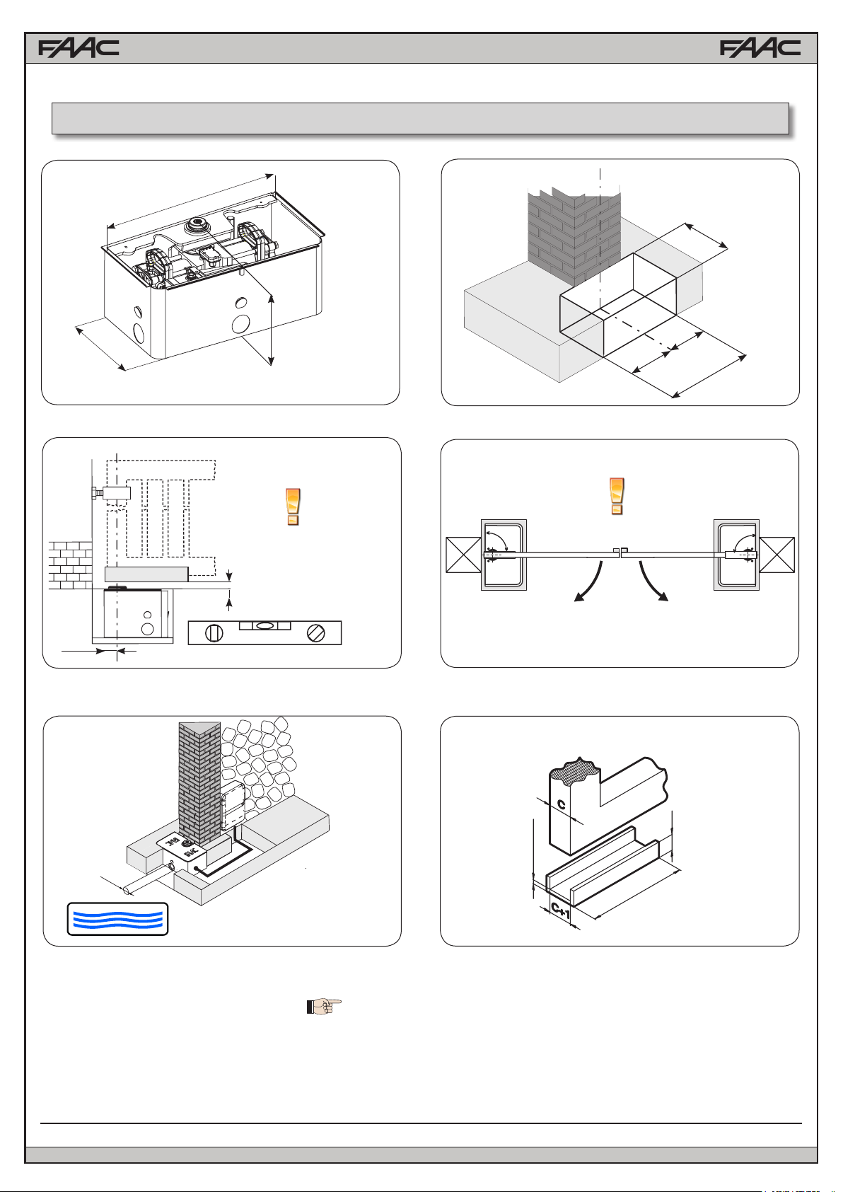
2. INSTALL THE LOAD BEARING BOX
10
5/8
”
7/8
18
”
B=9 13/16”
1
14
3/16
=
=
22
7/8
”
3
1 27/32”
2
”
4
90°90°
2 1/4”
2”
Drain
5
Dimensions in inches
6
≥ 1 1/2”
≥ 3/8”
≥ 10”
FAAC Model S800H Swing Gate Operator
7
Page 8
TO ENSURE CORRECT INSTALLATION,
THE LEAF ROTATION AXIS MUST BE
PERFECTLY ALIGNED WITH THE OPERATOR (Fig. 7)
7
8
8
FAAC Model S800H Swing Gate Operator
Page 9
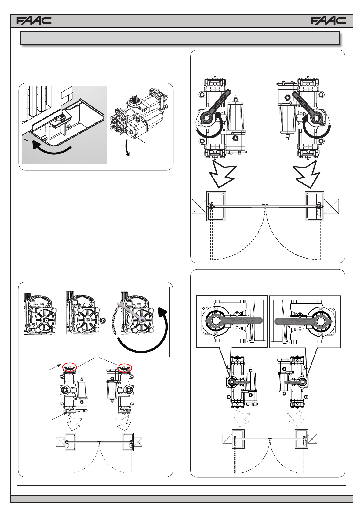
3. INSTALL THE OPERATOR
1) Move the gate to its open position.
2) Referring to the instructions in chapter 4.1, hydraulically release
the operator, using the release screw (Fig. 3 ref.1)
1
x 1
Fig.3
3) On the operator, unscrew the plug (Fig.4 ref. A) of the screw of
the closing travel limit device (Fig.4 ref. 1) and check if the screw
is completely tight.
4) Unscrew the closing travel limit screw (Fig.4 ref. B) by
one turn (IMPORTANT FOR CORRECT COUPLING OF THE
PINION-GROOVED BUSHING DURING INSTALLATION).
5) Turn the operator pinion with the supplied wrench (Fig. 5
ref. 1), in the gate closing direction as shown in Fig.5, up to the
internal stop point of the piston, and remove the wrench.
6) Without moving the pinion, insert the supplied wrench on
the operator as shown in Fig.6, and make sure that it indicates 0
(ZERO) on the operator’s plastic panel (Fig.6 ref.1). If necessary
rotate the pinion. (IMPORTANT FOR CORRECT COUPLING
OF THE PINION-GROOVED BUSH DURING INSTALLATION).
A
B
TURN THE KEY UNTILL IT REACHES THE MECHANICAL
STOP-POINT AND REMOVE IT FROM THE PINION
1
1
Fig.5
INSERT THE KEY WITHOUT MOVING THE PINION
AND CHECK IF IT INDICATES ZERO
1
90
1
90
TRAVEL-LIMIT
STOP
AT CLOSING
TRAVEL-LIMIT
STOP AT OPE-
NING
FAAC Model S800H Swing Gate Operator
1
x 1
Fig.4
0
90
90
0
90
0
90
Fig.6
9
Page 10
NOTE: if necessary, lightly tighten the closing travel-limit screw
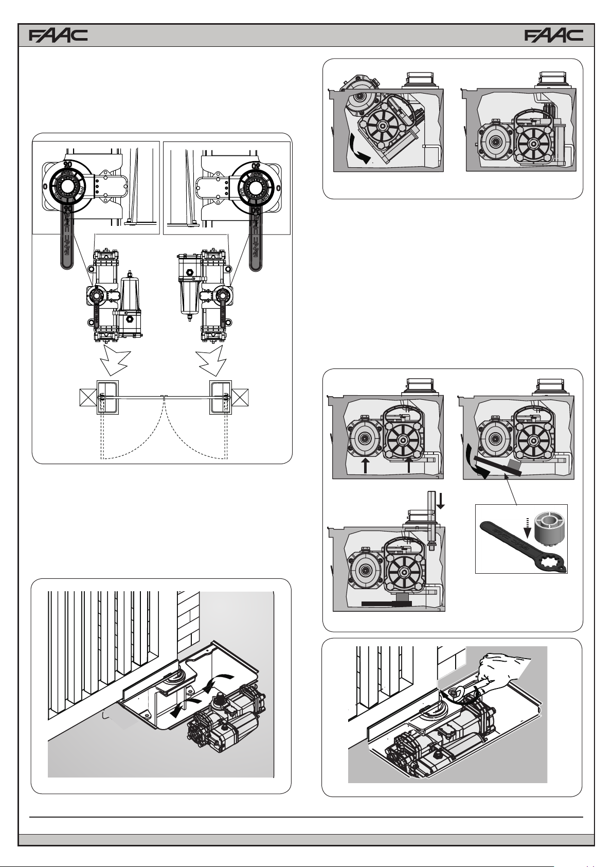
7) Turn the operator pinion with the supplied wrench until the mark
point to 90
° and then remove the wrench (see Fig. 7)
Fig.9
10) Place the supplied plastic wrench with the spacer under the
operator, as shown in gure 10 ref. B, C
12) Insert and screw in the fastening screws with the supplied
lockwasher as shown in Fig. 10 ref. C, in order to secure the
operator to the load bearing box as shown in Fig. 11.
13) Close the gate and check if the closing travel-limit stop is
correctly positioned; if necessary, adjust the travel-limit stop,
referring to the instructions in paragraph 3.4.
14) Open the gate and check if the opening travel-limit stop is
correctly positioned; if necessary, adjust the travel-limit stop,
referring to the instructions in paragraph 3.4.
15) Hydraulically re-lock the operator as per instructions in
chapter 4
Fig.7
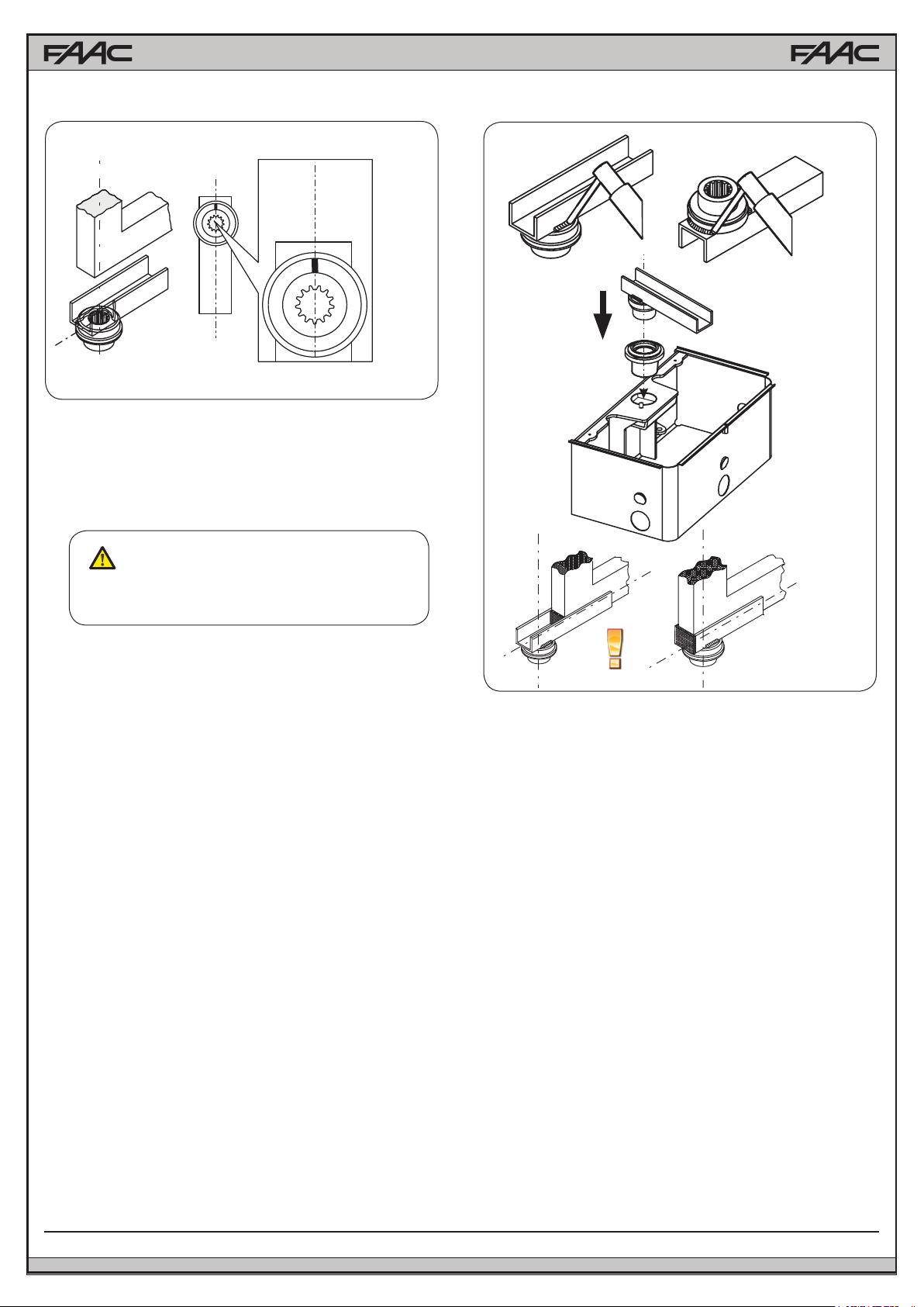
8) Grease the pinion and insert the operator in the load bearing
box as shown in Fig.8-9,
9) Raise the operator with its handles (Fig.10 ref. A), inserting the
pinion in the grooved bushing of the bearing case. To facilitate the
operation, slightly rotate the operator until coupling takes place.
A
B
C
Fig.10
10
Fig.8
Fig.11
FAAC Model S800H Swing Gate Operator
Page 11

3.1 INTERNAL MECHANICAL POSITIVE STOPS
The S800H operator is supplied standard with internal opening
and closing mechanical stops. This is to facilitate the installation
operations because there is no need to build external mechanical
stops.
The mechanical travel-limit stops (POSITIVE STOPS) can be
adjusted in the last 30° of the operator’s MAXIMUM travel, at
both opening and closing.
FAAC SUPPLIES THE TRAVEL LIMIT DEVICES TOTALLY OPEN
( MAXIMUM PINION ROTATION ANGLE ).
A B
3.2 ADJUSTMENT OF THE TRAVEL-LIMIT STOPS
1) Hydraulically release the operator. (See chapter 4.1)
2) Close the leaf, manually taking it into its closed position.
3) Unscrew the cap (Fig.12 ref.A) of the closing travel-limit screw
(Fig.12 ref.1)
4) UNSCREW the travel-limit stop screw (Fig.12 ref.B) at closing
(Fig.12 ref.1), until the leaf begins to move.
5) Fasten the supplied U-bracket (Fig.13) on the travel-limit stop
screw.
6) Open the leaf, manually taking it into its opening position.
7) Unscrew the cap of the screw (Fig.12 ref.A) of the opening
travel-limit stop (Fig.12 ref.2).
8) UNSCREW the travel-limit stop screw (Fig.12 ref. 2), until the
leaf begins to move.
9) Fasten the supplied U-bracket (Fig.13) on the travel-limit stop
screw.
10) Open and close the gate to check if the travel-limit stop is
correctly adjusted.
11) Re-lock the operator again, following the instructions in
chapter 4.1.
TRAVEL-LIMIT STOP AT CLOSING
1
TRAVEL-LIMIT
STOP AT OPENING
2
CLOSING POSITION
Fig.13
3.3 FINAL STEPS
1) Place the encoder in its slot on the motor (See Fig. 14).
2) Connect the motor (Fig.1 ref. 8) and the encoder (Fig.1
ref. 9) to the control unit, following the specic instructions.
3) Secure the cover of the load bearing box with the supplied
screws (Fig.15;16).
4) Place the warning sings on both sides of the gate
Fig.14
FAAC Model S800H Swing Gate Operator
OPENING POSITION
Fig.12
Fig.15
Fig.16
11
Page 12

4. MANUAL OPERATION
MAKE SURE TO CUT POWER BEFORE RELEAS-
ING OR LOCKING THE OPERATOR
4.1 BUILT IN HYDRAULIC RELEASE
If the gate has to be moved manually due to a power cut or
fault of the automated system, you can use the hydraulic
release device with the release key (Fig.17):
1) Remove the cover from the bearing case.
2) Turn the release screw
- To RELEASE, turn the screw counter-clockwise by one turn.
(DO NOT COMPLETELY UNFASTEN THE SCREW TO AVOID
SPILLING THE OIL.
- To re-engage the hydraulic operation, turn the screw
clockwise up to the mechanical stop point. (DO NOT
OVERTIGHTEN)
4.2.1 INSTALLATION PROCEDURE
1) Release the operator using the built in hydraulic release
2) Fasten the external release body to the load bearing box
system using the two supplied M8 screws (g. 19 ref. 1)
3) Remove the bleed unions on the operator, then connect
those supplied with the release system (Fig. 19 ref. 2
3) Re-lock the built in manual release.
1
RELEASE SCREW
Fig.17
4.2 EXTERNAL HYDRAULIC RELEASE
The S800H operator kit comes with a eld installable hydraulic
manual release, that can be conveniently mounted on top of
the load bearing box
Fastening bolts for the release system
Bleed screws
Hydraulic Hose
Banjo Bolt
2
Fig. 19
4.2.2 BLEEDING PROCEDURE
The installation of the hydraulic release could have let air in the
circuit, causing irregular operation like an incorrect movement
of the leaf and excessive noise during operation.
To solve this problem, operate as follows:
1) Command an opening movement of the gate.
2) During the leaf movement, loosen the opening bleed screw
(Fig.20 ref.1 )
3) Let air come out from the hydraulic circuit through the bleed
screw until non-emulsied oil comes out.
4) Tighten the bleed screw before the operator ends the opening
cycle.
5) Command a closing movement of the gate.
6) During the leaf movement, loosen the closing bleed screw
(Fig.20 ref. 2)
7) Let air come out from the hydraulic circuit through the bleed
screw until non-emulsied oil comes out.
8) Tighten the bleed screw before the operator ends the closing
cycle.
9) Repeat the operations, if necessary.
10) Restore the oil level until it is just under the cap, using the
oil supplied (Fig. 21 ref.1).
12
Union bolt
Fig. 18
FAAC Model S800H Swing Gate Operator
Page 13

1
1
2
2
Fig. 20
1
Fig.21
4.2.3 USING THE RELEASE SYSTEM
To release the operator, remove the plastic cover, insert the key
and turn the release lock counter-clockwise for about one turn.
(Fig. 22 ref. 1)
To lock the operator again, turn the release lock clockwise until
reaching the stop point, do not force (Fig. 22 ref. 2)
Fig. 22
5. MAINTENANCE
Run a functional check of the system at least every 6 months,
with special attention to the efciency of the safety and release
devices (including the thrust force of the operator), and to the
smooth operation of the gate hinges.
5.1 BLEEDING OPERATIONS
THE S800H OPERATOR IS SUPPLIED WITH THE
HYDRAULIC CIRCUIT ALREADY AIR FREE. DO NOT
BLEED. BLEEDING IS ONLY NECESSARY IN THE
EVENT OF MAINTENANCE OF THE HYDRAULIC
SYSTEM, OR INSTALLATION OF THE HYDRAULIC
MANUAL RELEASE
The presence of air in the hydraulic circuit causes the automated
system to operate incorrectly, i.e. a faulty movement of the leaf
and too much noise while operating. Please refer to the procedure
illustrated in paragraph 4.2.2 to correct this problem:
FAAC Model S800H Swing Gate Operator
13
Page 14

6. ENCODER CONNECTION
The S800H operator comes with an encoder system that
allows the control board to monitor the postion of the leaf
connected to the operator at any time. The proper assignment of the leaf to the corresponding encoder depends on
the connection of the two encoder wires (leaf 1- encoder 1;
leaf 2 - encoder 2).
NOTE: THE ENCODER WIRES MUST BE CONNECTED TO THE BUS CONNECTOR OF THE CONTROL BOARD.
Please refer to the E024U board pinout for more information
To verify the proper assignement of LEAF 1 - ENCODER 1 -
MOTOR 1 and LEAF 2 - ENCODER 2 - MOTOR 2, you can
use the LEDs visible through the encoder’s shell, as shown
in Figures 23 and 24:
To invert the leaf-encoder combination, change the encoder
polarity by swapping its wires until the right LEDs are lit.
DL1
DL2
OFF
DL1
ON
DL3
ON
DL2
ON
LEAF 1*
TWO LEDs ON
LEAF 2
ONE LED ON
OFF
DL3
OFF
Fig. 23
DL2
ON
DL1
ON
DL3
DL1
ON
DL2
OFF
LEAF 2
ONE LED ON
LEAF 1*
TWO LEDs ON
OFF
Leaf 1 opens rst and close second. if you do
not have a leaf overlap between 1 and 2, the
board may be set with leaf delay equal to zero
TABLE 1
LED ON STEADY FLASHING OFF
Power ON and encoder communicating
DL 1
with the control board
Power ON but encoder NOT communica-
ting with the board (eg: wiring error, both
encoders with the same polarity)
Switching the polarity of the encoder’s wires on the
board connector you can change the association of
the encoder to the leaf.
Power OFF and no communication (eg: no
power or no connection)
DL3
OFF
Fig. 24
DL 2 Encoder assigned to Leaf 1 / Encoder assigned to Leaf 2
DL 3 /
14
Encoder generating pulses during leaf
movement
FAAC Model S800H Swing Gate Operator
Leaf not moving
Page 15

7. S800H PARTS DIAGRAM
1 63000276 GASKET FOR TANK
2 7090010015 SEAL OR 4.48X1.78
3 7090030015 GASKET OR 6.75X1.78
4 703101 WASHER GROWER 4 1751 Z
5 701632 SCREW TCEI M4x25 UNI 5931 8G Z
6 7090030015 GASKET OR 6.75X1.78
7 63000266 24 V HYDR. UNIT TANK
9 63000306 N7MMR TYPE GASKET
10 63000376 S800H MOTOR FLANGE
11 7090100025 GASKET OR 72.69X2.62
13 63001665 S800H UL MOTOR CABLE
14 701103 TCEI 4X 12 5931 INOX
15 7090190015 GASKET OR 14.00X1.78
16 63002635 S800H MOTOR COVER
17 63000376 S800H MOTOR
18 701072 SCREW TCEI 5X 14 5931 8.8 Z
19 701975 SCREW TCEI M4x75 UNI 5931 INOX
20 701245 STEI M6x8 UNI 5925 + VEBLOCK 360°
21 63000256 BUSH FOR PUMP SHAFT
22 7110015 CAP
23 63000246 0.5 LT 10010 PUMP
24 63000226 CB FLANGE
FAAC Model S800H Swing Gate Operator
15
Page 16

1 63000016 ESCAPE VALVE GROUP
2 63000136 FLANGE LH
3 63002625 NR. 2 HANDLES
4 63000116 100° CYLINDER BARREL
5 63000125 ENCODER
6 63000005 ENCODER SUPPORT KIT
7 63000115 MAGNETIC DISC
8 63000076 UPPER BUSHING GROUP
9 63000176 OR 55.25x2.62 GASKET
10 63000186 IGUS CYLINDRICAL BUSH
11 490112 FOUNDATION BOX
12 714017 HYDRAULIC OIL LT. 1
13 63000006 GASKET KIT
14 63000106 PISTON
15 63000056 PISTON SHAFT
16 63000046 CENTRAL BODY
17 63000086 100° RACK
18 63000016 ESCAPE VALVE GROUP
19 63000146 FLANGE RH
20 63000036 POSITIVE STOP
21 63000156 100° FEEDING PIPE RH
22 63000066 LOWER BUSHING GROUP
23 63000206 IGUS CYLINDRICAL BUSH
24 63000196 OR3200 50.47x2.62 GASKET
26 7092025 BALS B275236 GASKET
27 7090635 SEAL ORM 5x1.5 (0050-15)
28 7090490025 GASKET OR 64.77X2.62
29 63002465 FOUNDATION PLATE
FAAC Model S800H Swing Gate Operator
16
Page 17

1. E024U CONTROL BOARD DESCRIPTION & CHARACTERISTICS
J24
SETTING
DL19 DL20 DL21 DL22DL14 DL15 DL16 DL17 DL18
+
1.1 TECHNICAL SPECIFICATIONS 1.2 LAYOUT AND COMPONENTS
Main power supply
Secondary power
supply
Power consumption
Max load per motor
Accessory power
supply
Battery charge current
Operating temperature
Protection fuses
Main power fuse
Operating Logics
Operating time out
115/230 V~ 50/60 Hz switchable
24 Vdc - 16 A max.
(min. 20 Vdc. - max. 36 Vdc.)
stand-by = 4W max. = 400 W
7 A
24 Vdc - 500 mA
150 mA
-4 °F.........+131 °F
All self-resetting
2.5 A Timed
E, A, S, EP, AP, SP, B, C
10 min.
Pause time Programmable (0 to 4 min)
with trimmer
Motor force, speed,
obstacle sensitivity,
closing delay
Connector inputs
Programmable with
dedicated trimmer
Power supply, Battery,
Radio receiver, USB
Terminal strip inputs Encoder, Open A, OpenB, Stop,
Open safety fotocell, Closing safety
fotocell, Limit switches
Terminal strip outputs Lamp, Buzzer, Motors, Lock,
Programmable OUT,
accessory power supply
Programming
With trimmers,
dipswitches
and pushbutton
RADIO
BATTERY
Connector for the radio receiver
Connector for the backup battery
J24 Jumper to disable battery charging
(With the jumper present the battery
is charged)
POWER SUPPLY
TR1 to TR6
+24 LED
SW1 - SETUP
DS1 - DS2
LED ERROR
USB A
DC Power supply input
Programming Trimmers
DC power indicator
Pushbutton for automatic setup
Programming dipswitches
Troubleshooting indicator
USB connection for software upgrade
1.3 RADIO CONNECTION
On the radio connector it’s possible to plug in receivers RP
and RP2. With a single channel radio RP it will be possible to
activate only the OPEN A input, with a dual channel radio RP2
it will be possible to activate both OPEN A and OPEN B inputs.
Plug in the radio board with the component side towards the
internal part of the board.
Make sure you insert or disconnect the board ONLY with the
power off.
Fig. A1
A2
E024U CONTROL BOARD
Page 18

2. INPUT / OUTPUT DESCRIPTION
A B STP CL OP
OPEN FSW
Fig. A2
PIN LABEL FUNCTION
2 EASY 2 EASY Input for bus 2easy accessories (encoder)
1 OPEN A N.O. Contact for total opening command
2 OPEN B /
CLOSE
3 STOP N.C. Contact for stop command
4 FSW CL N.C. Contact for closing safety
5 FSW OP N.C. Contact for opening safety
6 GND (-) 24 Vdc negative
7 GND (-) 24 Vdc negative
8 + 24 24 Vdc positive
9 OUT (-) Programmable output (See: DS1 SW 11-12)
10 FCA 1 Open limit switch Motor 1
11 GND (-) 24 Vdc negative
12 FCC 1 Close limit switch Motor 1
13 FCA 2 Open limit switch Motor 2
14 GND (-) 24 Vdc negative
15 FCC2 Close limit switch Motor 2
LAMP LAMP Audio alarm output (DS1 SW11=OFF)
LOCK LOCK Output for electrical lock, max 5A pulse (DS2 - SW 4=OFF) 12 Vac / 24Vdc
Always ON (maglock): max 1 A (DS2 - SW 4=ON) 24 Vdc
OPEN B: N.O. Contact for opening of leaf 1 only
(with only one leaf the opening stops at 50% of traveling)
CLOSE (LOGIC B-C): N.O. Contact for closing command
Output for ashing light 24Vdc 15W max (DS1 SW11=ON)
MOT1 MOT 1 Motor 1 output ( rst moving motor )
MOT2 MOT 2 Motor 2 output ( second moving motor )
USB A USB Firmware upgrade input
E024U CONTROL BOARD
A3
Page 19

3. PHOTOCELLS CONNECTIONS
How to connect Normally Open contacts.
(Connect them in parallel)
Fig. A3
The E024U board allows the connection of several safety devices
(for example photocells). With photocells you can activate the
FAILSAFE function, which, before each movement of the operator, tests each fotocells. In case the test fails the movement
is inhibited. To activate this function set to ON the dip-switch N.
11 and 12 of DS1, and connect the negative of the transmitter
to the OUT pin (No.9).
The photocells must be connected depending on which area
they must protect. (See Fig. A5)
Closing Safety D : These photocells protect the area covered
by the gate during the closing movement. They have no effect
during the opening movement.
Opening Safety B-C : These photocells protect the area covered
by the gate during the opening movement. They have no effect
during the closing movement.
Opening/Closing Safety A : These photocells protect the area
covered by the gate both during the opening and the closing
movements.
How to connect Normally Close contacts.
(Connect them in series)
Fig. A4
Fig. A5
3.1 CONNECTIONS TO NORMALLY CLOSE (N.C.) PHOTOCELLS
Connection of a pair of closing photocells and a pair of opening/closing photocells
FSW
STP CL OP
RX= Photocell Receiver
TX= Ptotocell Transmitter
CL= Closing
OP= Opening
A4
Fig. A6
To use the FAIL-SAFE mode connect the negative power supply of the transmitters to OUT (pin 9), and set dip-
switch 11 and 12 to ON on DS1
E024U CONTROL BOARD
Page 20

FSW
Connection of two pairs of closing photocells
STP CL OP
Other optional safety devices to connect in series
RX= Photocell Receiver
TX= Ptotocell Transmitter
CL= Closing
OP= Opening
To use the FAIL-SAFE mode connect the negative power supply of the transmitters to OUT (pin 9), and
set dip-switch 11 and 12 to ON on DS1
When using the FAIL-SAFE mode also the safety inputs not used (FSW CL , FSW OP) must be connected
to OUT (pin No. 9)
Connection of a pair of closing photocells, a pair of opening photcells and a pair of opening/closing photocells
FSW
STP CL OP
RX= Photocell Receiver
TX= Ptotocell Transmitter
CL= Closing
OP= Opening
Fig. A7
To use the FAIL-SAFE mode connect the negative power supply of the transmitters to OUT (pin 9),
and set dip-switch 11 and 12 to ON on DS1
E024U CONTROL BOARD
Fig. A8
A5
Page 21

8
Connection of a pair of closing photocells and a pair of opening photocells
FSW
STP CL OP
RX= Photocell Receiver
TX= Ptotocell Transmitter
CL= Closing
OP= Opening
To use the FAIL-SAFE mode connect the negative power supply of the transmitters to OUT (pin 9), and set dip-
switch 11 and 12 to ON on DS1
Connection of no safety or stop devices
(NOT RECOMMENDED)
FSW
STP CL OP
Fig. A10
Connection of a generic closing safety device and a generic
open safety device
FSW
STP CL OP
Fig. A9
Connection of one pair of opening photocells
FSW
STP CL OP
Other optional safety devices to
connect in series
8
To use the FAIL-SAFE mode connect the ne-
gative power supply of the transmitters to OUT
(pin 9), and set dip-switch 11 and 12 to ON on
DS1
When using the FAIL-SAFE mode also the
safety inputs not used (FSW CL , FSW OP)
Fig. A11
A6
must be connected to OUT (pin No. 9)
E024U CONTROL BOARD
Fig. A12
Page 22

4. PROGRAMMING
4.1 DIP SWITCH DS1 SETTINGS FOR OPERATING LOGIC
OPERATING LOGIC
DS 1: SW 1 - SW 2 - SW 3
LOGIC
E (default)
Semiautomatic
A
Automatic
S
Security
EP
Semiautomatic
step by step
AP
Automatic
step by step
SP
Security
step by step
B
Manned Pulsed
C
Manned Constant
SW 1SW 2SW 3PAUSE
OFF OFF OFF NO
ON ON ON
OFF OFF ON
OFF ON OFF NO
OFF ON ON
ON OFF OFF
ON OFF ON NO
ON ON OFF NO
TIME
0 - 4
min
0-4
min
0-4
min
0-4
min
One command opens, the next one closes. A command du-
One command opens, waits for the pause time an then closes
One command opens, waits for the pause time and then closes automatically. If the closing safety is activated or another
command is given during the pause time it closes
One command opens, the next one closes. During the move-
One command opens, waits for the pause time and then clo-
ses automatically. A command during the pause time holds
One command opens, waits for the pause time and then
closes automatically. If the closing safety is activated during
pause time the gate closes in 5 s. A command during pause
An open A command opens the gate, an open B command
Holding open A active opens the gate, holding Open B active
DESCRIPTION
ring opening stops the gate
automatically
ment a command stops the gate
the gate open
time holds open the gate
closes the gate
closes the gate
For more details on the operating logics please refer to Chapter 12 - Function Logics
E024U CONTROL BOARD
A7
Page 23

4.2 ADJUSTING TRIMMERS
TR1 – FORCE ADJUSTMENT MOTOR 1
Turn clockwise to increase the opening and closing force
TR 2 – FORCE ADJUSTEMENT MOTOR 2
Turn clockwise to increase the opening and closing force
TR 3 – SPEED ADJUSTMENT FOR MOTOR1 AND MOTOR 2
Turn clockwise to increase the opening and closing speed
TR 4 – SENSITIVITY ADJUSTEMENT FOR OBSTACLE DETECTION FOR MOTOR 1 AND MOTOR 2
Turn clockwise to increase the sensitivity for obstacle detection.
6
With this trimmer you can adjust the reaction time for the board to invert the motion of the gate in case of
obstacle detection, or the complete stop in case the board is in the positive stop detection zone.
If an obstacle is detected during the gate movement the board will invert the motor rotation until the gate goes
back to the original starting position. If in the successive movement an obstacle is detected again the board
will be put in alarm mode and won’t take any more commands until the STOP input is activated (Alarm Reset)
or power is cycled
TR 5 – PAUSE TIME ADJUSTMENT ( 0 - 4 min. )
Turn clockwise to increase the pause time.
1 min
30 sec
2 min
3 min
Dip switches DS1: 1 to 3 need to
be set for an operating mode with
PAUSE time for this adjustment
to have any effect
4 min0 sec
TR6 - CLOSING DELAY OF LEAF 1 OVER LEAF 2 ADJUSTMENT ( 0 - 15 sec )
Turn clockwise to increase the delay
E024U CONTROL BOARD
A8
Page 24

4.3 DIP SWITCH DS1 SETTINGS FOR BOARD SETUP
BOARD SETUP
DS 1: SW 4 to SW 12
OPENING DELAY
0 sec (default)
2 sec
REVERSE AND LAST STROKE
inactive (default)
active
MAX THRUST AT STARTUP
inactive (default)
active for 3 sec
AUTOMATIC OPENING IN CASE OF
POWER FAILURE
inactive (default)
active
CLOSING SAFETY LOGIC
immediate reverse (default)
reverse when cleared
PREFLASHING
inactive (default)
active for 5 sec
EXTRA SENSITIVITY TO
OBSTACLE DETECTION
inactive (default)
active
ORANGE TERMINAL FUNCTION
Audio Alarm (default)
SW 4
OFF
ON
SW 5
OFF
ON
SW 6
OFF
ON
SW 7
OFF
ON
SW 8
OFF
ON
SW 9
OFF
ON
SW 10
OFF
ON
SW 11
OFF
The opening of leaf 2 is delayed after the opening of leaf 1. This is to avoid
that the gate’s leafs interfere with each other during the initial part of the
movement. In case there is only one leaf is has no effect.
If active, before opening, while the gate is closed, the motors thrust to
close for 2 s to facilitate the release of the electric lock. At closing the
motors are activated for a nal stroke after slowdown to facilitate locking
of the electric lock.
With this fuction active the motors work at maximum force at startup
(regardless of the force setting) during the initial phase of the movement.
Useful for heavy leafs
If active and with the optional backup battery installed, the board will
open the gate after one minute from the power failure and keep it open.
Within the minute wait it’s always possible to open and close the gate
with a command. If the logic used has a pause time the board will close
the gate when the power comes back.
With this function you can choose the behaviour of the closing safety. With
SW8 OFF the gate movement will be reversed as soon as the safety is active,
with SW8 ON the gate will stop when the safety is active and it will reverse
only when the safety is deactivated again.
This function activates the ashing lamp for 5s before the movement of
the gate
If active this function allows to have an immediate reverse in case the
gate hits a rigid obstacle, while keeping the motor active in case of a
gradual increment of resistance, like with wind pressure on the gate or
increased friction
If OFF after the second consecutive obstacle detection this output is
activated until the STOP contact is open or the power is cycled
if ON the output can be connected to a warning lamp.
NOTE: for UL325 compliance this switch must be left OFF
Warning Lamp
OUT FUNCTION (pin 9)
max 100mA
Lamp
Photocells FAIL SAFE active
E024U CONTROL BOARD
ON
SW 12
OFF
ON
if OFF: use pin 9 as power supply negative for a warning lamp. The
lamp will be active during opening, pause and stop. Flashing during
close, off when the gate is closed
If ON: use pin 9 as power supply negative for the safety photocells.
Before any movement the board will check for the presence of the
safety photocells. If the test fails the gate will not move.
A9
Page 25

+
4.4 DIP SWITCH DS2 SETTINGS FOR OPERATOR TYPE AND LOCK MODE
IMPORTANT
DS2
DS 2
OPERATOR SELECTION
OPERATOR TYPE SW 1 SW 2 SW 3
S450H, S800H OFF OFF OFF
S418 OFF OFF ON
415, 390, 770 ON OFF OFF
5. LED DIAGNOSTICS
DS 2
LOCK OUTPUT MODE
OUTPUT MODE SW 4
Active only for 3 sec. after an open impulse
(from gate closed)
Active always except 3 sec. before an opening
J24
1
2
OFF
ON
+
A10
6
5
7
3
BUS
DEVICE
8 9
DL14 DL15 DL16 DL17 DL18
SETTING
4
10
DL19 DL20 DL21 DL22
E024U CONTROL BOARD
Page 26

L
E
DESCRIPTION
D
1
2
LED BATTERY
LED +24 Main power present Main power OFF
LED SET-UP
Board working on AC
In BOLD the normal state with gate closed and working
ON STEADY OFF BLINKING
power
battery power or ext
3
4
5
6
7
8
LED ERROR Board malfunction No errors Error conditions. See LED ERROR
Communication bus
LED BUS_MON Communication on
Bus “2easy” OK
LED USB
RESERVED
LED DL 14
OPEN A INPUT (N.O.)
LED DL 15
OPEN B INPUT (N.O.)
LED DL 16
STOP INPUT (N.C.)
OPEN A active OPEN A not active
OPEN B active OPEN B not active
STOP non active STOP active or
“2Easy” inactive. Verify
the bus “2Easy” devices
Software update done
or USB key not present
LED STATUS
Board working on
supply
Normal operation
for shorts
wiring error
Battery charging
SLOW BLINK
(1 sec. ON - 1 sec. OFF)
SET-UP needed
FAST BLINK
(0.5 sec. ON - 0.5 sec OFF)
SET UP in in progress
DISPLAY table
Bus 2Easy devices with the
Same address. Verify dip switch
Setting on photocells or
Encoder LEDs
USB key inserted and software
Update in progress
(DON’T Remove the USB key)
LED DL 17
FSW CL INPUT (N.C.)
LED DL 18
FSW OP INPUT (N.C.)
LED DL 19 FCA1
OPEN LIMIT SWITCH MO-
9
CLOSE LIMIT SWITCH MO-
OPEN LIMIT SWITCH MO-
10
CLOSE LIMIT SWITCH MO-
TOR1 (N.C.)
LED DL 20 FCC1
TOR1 (N.C.)
LED DL 21 FCA2
TOR2 (N.C.)
LED DL 22 FCC2
TOR2 (N.C.)
Closing safety
devices clear
Opening safety
devices clear
Limit switch
OFF or not used Limit Switch activated
Limit switch
OFF or not used Limit Switch activated
Limit switch
OFF or not used Limit Switch activated
Limit switch
OFF or not used Limit Switch activated
Closing safety devices
triggered or wiring error
Opening safety devices
triggered or wiring error
E024U CONTROL BOARD
A11
A11
Page 27

The diagnostic LED shows only one error condition at a time, with the priority of the below table. In case there is more
than one error once one is eliminated the LED will show the next
NUMBER OF
FLASHES
1
2
3
4
5
6
7
8
LED ERROR DISPLAY
ERROR CONDITION SOLUTION
OBSTACLE DETECTION Remove the obstacle
BOARD IN SLEEP MODE
(Slow blinking means that the automatic open
in case of power failure function is active)
MOTOR 1 FAILURE Replace motor 1
MOTOR 2 FAILURE Replace motor 2
ENCODER on motor 1 or motor 2 broken or
wiring error
FAIL SAFE FAILED Verify the photocells wiring and alignement
BOARD THERMAL PROTECTION ACTIVE Turn off the board and wait until the components cool down
MAX RUN TIME REACHED
WITHOUT FINDING THE
POSITIVE STOP (10 min. )
Verify the encoder wiring and LED status. If they are correct replace
- Verify that the operator manual release is not engaged
- Verify that the board recognizes the mechanical stop, in
Verify the presence of AC power
the encoder
case redo the setup procedure
6. TIME LEARNING (SET-UP)
After powering up the board for the rst time or when the board
will need it the setup LED will blink at a slow frequency to indicate
that the setup procedure to learn the running times is needed.
The setup can be redone at any time by pressing and holding
the setup button as indicated below.
After the setup rst movement, if the leafs are opening instead
of closing you need to reverse the wires going to the motor that
moves in the wrong direction
6.1 AUTOMATIC TIME LEARNING
WARNING: If the time learning setup is done automatically then
the slow down points are set by the board on his own
Move the leafs to the mid position
Very important for a good result
1. Press and hold the SETUP button until the SETUP LED
lights up, wait about 3 sec. until it turns off and then release
it immediately. NOTE: If you wait too long to release it the
manual set-up will start. The LED will blink during the setup
procedure
2. Leaf 2 (if present) starts to move slowly in closing direction,
stopping when it reaches the mechanical stop or FCC2.
3. Leaf 1 begins to move slowly in closing direction, stopping
when it reaches the mechanical stop, or FCC1.
4. Leaf 1 starts to move slowly in opening direction, followed
by leaf 2 (if present) still slowly.
5. When they both reach the open mechanical stop or FCA1 and
FCA2 they stop and reverse, leaf 2 (if present) automatically
starts closing at full speed followed by leaf 1.
6. When they reach the close mechanical stop or FCC1 and
FCC2 both leafs stop and leaf 1 restarts automatically opening at full speed followed by leaf 2 (if present).
7. If you selected an automatic logic the board will wait for the
pause time and then closes the gate automatically. Otherwise you have to give an OPEN command to close the gate.
6.2 MANUAL TIME LEARNING
WARNING: If the manual time learning setup is done then
the slow down points must be set by the installer during the
procedure
Move the leafs to the mid position
Very important for a good result
1. Press and hold the SETUP button until the SETUP LED
lights up, keep it pressed for about 3 sec. until it turns off and
keep it pressed more until the leaf 2 (if present) starts moving slowly. The LED will blink during the setup procedure
2. Leaf 2 will move in closing direction until it reaches the
mechanical stop or FCC2
3. Leaf 1 starts moving slowly until it reaches the mechanical
stop or FCC1
4. Leaf 1 starts moving in opening direction at the set speed
(trimmer speed).
5. At the point where you want the slowdown to start give an
OPEN A command with the push button or the remote that
is already stored in memory. Leaf 1 starts to slow down
and stops when it reaches the mechanical stop or FCA1.
6. Leaf 2 starts moving in opening direction at the set speed
(trimmer speed)
A12
E024U CONTROL BOARD
Page 28

7. At the point where you want the slowdown to start give an
OPEN A command with the push button or the remote that
is already stored in memory. Leaf 2 starts to slow down and
stops when it reaches the mechanical stop or FCA2.
8. Leaf 2 starts to close at the set speed (trimmer speed).
9. At the point where you want the slowdown to start give an
OPEN A command with the push button or the remote that
is already stored in memory. The leaf 2 starts to slow down
and stops when it reaches the mechanical stop or FCC2.
10. Leaf 1 starts to close at the set speed (trimmer speed).
11. At the point where you want the slowdown to start give an
OPEN A command with the push button or the remote that
is already stored in memory. Leaf 1 starts to slow down and
stops when it reaches the mechanical stop or FCC1.
12. The manual time learning procedure is complete.
6.3 OBSTACLE DETECTION FUNCTION
The obstacle detection function is achieved by controlling the
current absorption and / or through the encoder connected to
the motors.
If the gate encounters an obstacle during the movement of
opening or closing, the obstacle detection function is activated
and the operator reverses the direction of the gate.
In case of a second consecutive obstacle the operator stops
the gate right away and any further command is inhibited. To
re-enable the automation, you must remove power or open the
STOP contact input. Until this “reset” the Audio Alarm output
will be active.
Power outlet
and switch
DIN rail
Batteries
AC connection
Power Supply
Pushbutton
E24U board
7. ENCLOSURE
The E024U board is supplied on a panel that ts in a 16x14”
enclosure.
17 15/32”
On the back panel are installed the control board, the power
supply and additional accessories.
8. POWER CONNECTION
AC POWER GUIDELINES:
THE E024U control board and power supply uses a single
phase AC power line to operate, charge the batteries, and power
gate accessories. Use the following guidelines when installing
the AC power:
1. Check the local wiring codes in all cases and follow all local
building codes. Wiring and hookup should be performed by a
qualied electrician/installer only.
2. AC power should be supplied from a circuit breaker panel and
must have its own dedicated circuit breaker. This supply must
include a green ground conductor.
3. Use copper conductor wires with liquid tight exible conduit
UL listed for electric cable protection
14 AWG, 600V, 80°C
Terminal Block max Torque 2.1 Nm
15
15/32
”
E024U CONTROL BOARD
4. Properly ground the gate operator to minimize or prevent
damage from power surges and/or lightning. Use a grounding
rod if necessary. A surge suppressor is recommended for additional protection.
6 7/32”
A13
Page 29

AC POWER CONNECTION
+
J24
SETTING
+
DL 1
DL 2
DL 3
DL 4
DL 5
J24
+
To connect AC power to the controller:
1. Turn the circuit breaker for the AC gate operator power OFF
before connecting the AC input wires.
2. Turn OFF the Power Switch located on the left side of enclosure before connecting the AC input wires.
3. Connect the AC input wires to the AC terminal located on the
top left of the control box. See diagram below.
4. Batteries must be installed after the AC power is on. See
Battery Power Connection.
115V 60Hz 2.5A
9. BACKUP BATTERY
The E024U board allows the connection of a 24V backup battery to provide power to operate the gate during blackouts. For
more details about how the boards handles the loss of main
power and how to congure its behaviour please see par 4.3
and DS1 switch 7.
To connect the battery use the provided cable and plug it on the
BATTERY connector on the board. Plug the other end of the
cable to the batteries, red wire to +24 and black wire to GND.
8.1 POWER SUPPLY
The E024U board is powered by a high efciency switching power
supply that takes 115V or 230V in input and provides 36VDC to
power the board. The power supply is preset for 115V at the factory, consult with FAAC Tecnical Support for 230V wiring options.
115V
230V
9.1 DISABLE THE BATTERY CHARGER
To disable the battery charger unplug jumper J24
J24 PRESENT = BATTERY CHARGING ACTIVE
J24 NOT PRESENT = BATTERY CHARGING NOT ACTIVE
J2 4
A14
E024U CONTROL BOARD
Page 30

SETTING
+
DL 1
DL 2
DL 3
DL 4
DL 5
J2 4
10. FIRMWARE UPGRADE
The E024U board keeps the operating rmware in a eld programmable memory, it can be easily upgraded through the on
board USB port
11. FUNCTION LOGICS
LOGIC “E” PULSES
SYSTEM STATUS
CLOSED opens the leaves opens leaf 1 no effect
OPENING
OPEN
CLOSING
BLOCKED closes leaves closes leaves closes leaves
OPEN A OPEN B CLOSE STOP FSW OP FSW CL FSW CL/OP
stops operation
(1)
recloses leaves
immediately (1)
reopens leaves
immediately
stops operation
recloses leaves
immediately
reopens leaves
immediately
(1) if the cycle began with OPEN-B (leaf 1), both leaves are activated at opening
recloses
leaves
immediately
recloses
leaves
immediately
no effect stops operation no effect
For the upgrade you need a USB Flash Drive, where you have
to copy the le supplied by FAAC. Then follow these steps:
1. Disconnect the batteries if they are present.
2. Turn the AC power off and insert the Flash Drive into the
USB A input on the board
3. Turn the AC power back on. The USB2 LED will start to ash
to conrm the beginning of the software update. (WARNING: DON’T TURN THE POWER OFF OR REMOVE
THE FLASH DRIVE UNTIL THE USB2 LED TURNS OFF.
4. Wait until the USB 2 LED turns off
5. Remove the USB Flash drive.
6. Cycle power, reconnect the batteries if needed and execute
a new SETUP procedure (See chapter 6)
WARNING: Only upgrade the rmware with the proper le
supplied by FAAC. otherwise the board could be damaged
no effect
(OPEN disabled)
stops operation
no effect
(OPEN/CLOSE
disabled)
no effect
(OPEN/CLOSE
disabled)
no effect
(OPEN disabled)
immediately
reverses at
closing
no effect
no effect
(OPEN disabled)
no effect
no effect
no effect
(CLOSE disabled)
reverses at opening
no effect
(CLOSE disabled)
no effect
(OPEN disa-
bled)
stops and opens
at release (OPEN
stops - saves
CLOSE)
no effect
(OPEN/CLOSE
disabled)
stops and opens
at release (OPEN
stops - saves
CLOSE)
no effect
(OPEN stops -
saves CLOSE)
LOGIC “A” PULSES
SYSTEM STATUS
CLOSED
OPENING no effect (1) no effect
OPEN IN
PAUSE
CLOSING
BLOCKED closes leaves closes leaves closes leaves
OPEN A OPEN B CLOSE STOP FSW OP FSW CL FSW CL/OP
opens and closes
after pause time
reloads
pause time (1)
reopens leaves
immediately
opens leaf 1 and
closes after pause
time
reloads
pause time of
released leaf
reopens leaves
immediately
(1) if the cycle began with OPEN-B (leaf 1), both leaves are activated at opening
no effect
recloses leaves
immediately
recloses leaves
immediately
no effect stops operation no effect
A15
no effect
(OPEN disabled)
stops operation
stops operation no effect
no effect
(OPEN/CLOSE
disabled)
no effect
(OPEN disa-
bled)
reverses at
closing
no effect
(OPEN disa-
bled)
no effect
no effect
recharges
pause time
(CLOSE disa-
bled)
reverses at
opening
no effect
(CLOSE disa-
bled)
E024U CONTROL BOARD
no effect
(OPEN disa-
bled)
stops and
opens at
release (saves
CLOSE)
recharges
pause time
(CLOSE disa-
bled)
stops and
opens at
release (saves
CLOSE)
no effect
(OPEN/CLOSE
disabled)
Page 31

LOGIC “S” PULSES
SYSTEM STATUS
CLOSED
OPENING no effect (1) no effect
OPEN A OPEN B CLOSE STOP FSW OP FSW CL FSW CL/OP
opens and closes
after pause time
opens released
leaf and closes
after pause time
no effect
recloses leaves
immediately
no effect
(OPEN disa-
stops operation
bled)
no effect
(OPEN disa-
bled)
reverses at
closure
no effect
continues
to open and
recloses
immediately
no effect
(OPEN disabled)
stops and opens
at release
(saves CLOSE)
OPEN IN
PAUSE
CLOSING
BLOCKED closes leaves closes leaves closes leaves
LOGIC “EP” PULSES
SYSTEM STATUS
CLOSED opens the leaves opens leaf 1 no effect
OPENING stops operation (1) stops operation
OPEN
CLOSING stops operation stops operation no effect stops operation no effect
recloses leaves
immediately (1)
reopens leaves
immediately
OPEN A OPEN B CLOSE STOP FSW OP FSW CL FSW CL/OP
recloses leaves
immediately (1)
recloses leaves
immediately
reopens leaves
immediately
(1) if the cycle began with OPEN-B (leaf 1), both leaves are activated at opening
recloses leaves
immediately
recloses leaves
immediately
no effect stops operation no effect
recloses
leaves
immediately
recloses
leaves
immediately
stops operation no effect
no effect
(OPEN/CLOSE
disabled)
no effect
(OPEN disabled)
stops operation
no effect
(OPEN/CLOSE
disabled)
(OPEN disa-
(OPEN disabled)
immediately
reverses at
no effect
bled)
no effect
closure
no effect
stops and, at
release, closes
reverses at opening
(see DS1-SW8)
and closes imme-
diately at end
no effect
(CLOSE disa-
bled)
no effect
no effect
no effect
(CLOSE disa-
bled)
reverses at
opening
stops and, at
release, closes
stops and opens
after release and
closes immediately
at end
no effect
(OPEN/CLOSE
disabled)
no effect
(OPEN disabled)
stops and opens
at release
(OPEN stops -
saves CLOSE)
no effect
(OPEN/CLOSE
disabled)
stops and opens
at release
(OPEN stops -
saves CLOSE)
restarts moving in
BLOCKED
LOGIC “AP” PULSES
SYSTEM STATUS
CLOSED
OPENING
OPEN IN PAUSE
CLOSING
BLOCKED closes leaves closes leaves closes leaves
opposite direction.
Always closes
after STOP
OPEN A OPEN B CLOSE STOP FSW OP FSW CL FSW CL/OP
opens and closes
after pause time
stops operation
(1)
stops operation
(1)
reopens leaves
immediately
restarts moving in
opposite direction.
Always closes
after STOP
(1) if the cycle began with OPEN-B (leaf 1), both leaves are activated at opening
opens leaf 1 and
closes after pause
time
stops operation
stops operation
reopens leaves
immediately
closes leaves
no effect
recloses
leaves
immediately
recloses
leaves
immediately
no effect stops operation no effect
no effect
(OPEN/CLOSE
disabled)
no effect
(OPEN disabled)
stops operation
stops operation no effect
no effect
(OPEN/CLOSE
disabled)
no effect
(OPEN disabled)
no effect
(OPEN disa-
bled)
reverses at
closing (saves
OPEN)
no effect
(OPEN disa-
bled)
no effect
(CLOSE disa-
bled)
no effect
no effect
recharges
pause time
(CLOSE disa-
bled)
reverses at
opening
(see
DS1-SW8)
no effect
(CLOSE disa-
bled)
no effect
(OPEN stops -
saves CLOSE)
no effect
(OPEN disabled)
stops and opens
at release
(OPEN stops -
saves CLOSE)
recharges
pause time
(CLOSE disa-
bled)
stops and opens
at release
(OPEN stops -
saves CLOSE)
no effect
(OPEN/CLOSE
disabled)
E024U CONTROL BOARD
(1) if the cycle began with OPEN-B (leaf 1), both leaves are activated at opening
A16
Page 32

LOGIC “SP” PULSES
SYSTEM STATUS
CLOSED
OPENING
OPEN IN PAUSE
CLOSING stops operation stops operation no effect stops operation no effect
BLOCKED
LOGIC “B” PULSES
SYSTEM STATUS
CLOSED opens the leaves no effect no effect
OPENING no effect closes leaves closes leaves stops operation
OPEN no effect closes leaves closes leaves
CLOSING opens the leaves no effect no effect stops operation no effect
OPEN A OPEN B CLOSE STOP FSW OP FSW CL FSW CL/OP
opens and clo-
ses after pause
time
stops operation
(1)
recloses
leaves
immediately (1)
restarts moving
in opposite
direction. Always
closes after
STOP
OPEN A OPEN B CLOSE STOP FSW OP FSW CL FSW CL/OP
opens leaf 1 and
closes after pause
time
stops operation
recloses leaves
immediately
restarts moving in
opposite direction.
Always closes
after STOP
(1) if the cycle began with OPEN-B (leaf 1), both leaves are activated at opening
no effect
recloses
leaves
immediately
recloses
leaves
immediately
recloses
leaves
immediately
no effect
(OPEN disabled)
stops operation
stops operation no effect
no effect
(OPEN/CLOSE
disabled)
no effect
(OPEN disabled)
no effect
(OPEN/CLOSE
disabled)
no effect
(OPEN disa-
reverses at
no effect
(OPEN disa-
(OPEN disabled)
bled)
closure
bled)
no effect
reverses at
closure
no effect
no effect
continues to open
and recloses
immediately
stops and, at
release, closes
reverses at opening
no effect
(CLOSE disabled)
no effect
no effect
no effect
(CLOSE disa-
bled)
reverses at
opening
no effect
(OPEN disa-
bled)
stops and opens
after release and
closes immediately
at end (OPEN stops
- saves CLOSE)
stops and, at
release, closes
stops and
opens at
release (saves
CLOSE)
no effect
(OPEN/CLOSE
disabled)
no effect
(OPEN disa-
bled)
stops and, at
release, closes
(saves
OPEN/CLOSE)
no effect
(OPEN/CLO-
SE disabled)
stops and
opens at
release
(saves
OPEN/CLOSE)
BLOCKED opens the leaves closes leaves closes leaves
LOGIC “C” CONTINUOS COMMANDS PULSES
SYSTEM STATUS
CLOSED opens the leaves no effect no effect
OPENING no effect closes leaves closes leaves stops operation
OPEN no effect closes leaves closes leaves
CLOSING opens the leaves no effect no effect stops operation no effect
BLOCKED opens the leaves closes leaves closes leaves
OPEN A OPEN B CLOSE STOP FSW OP FSW CL FSW CL/OP
no effect
(OPEN/CLOSE
disabled)
no effect
(OPEN disabled)
no effect
(OPEN/CLOSE
disabled)
no effect
(OPEN/CLOSE
disabled)
no effect
(OPEN disabled)
no effect
(OPEN disabled)
reverses at
closure
no effect
no effect
(OPEN disabled)
no effect
(CLOSE disa-
bled)
no effect
no effect
no effect
(CLOSE disa-
bled)
reverses at
opening
no effect
(CLOSE disa-
bled)
no effect
(OPEN/CLO-
SE disabled)
no effect
(OPEN disa-
bled)
stops and, at
release, closes
(saves
OPEN/CLOSE)
no effect
(OPEN/CLO-
SE disabled)
stops and
opens at
release
(saves
OPEN/CLOSE)
no effect
(OPEN/CLO-
SE disabled)
A17
E024U CONTROL BOARD
Page 33

LIMITED WARRANTY
To the original purchaser only:
FAAC International, Inc., warrants, for twentyfour (24) months from the date of invoice, the
gate operator systems and other related systems
and equipment manufactured by FAAC S.p.A.
and distributed by FAAC International, Inc., to be
free from defects in material and workmanship
under normal use and service for which it was
intended provided it has been properly installed
and operated.
FAAC International, Inc.’s obligations under this
warranty shall be limited to the repair or exchange
of any part of parts manufactured by FAAC
S.p.A. and distributed by FAAC International, Inc.
Defective products must be returned to FAAC
International, Inc., freight prepaid by purchaser,
within the warranty period. Items returned will
be repaired or replaced, at FAAC International,
Inc.’s option, upon an examination of the product
by FAAC International, Inc., which discloses, to
the satisfaction of FAAC International, Inc., that
the item is defective. FAAC International, Inc.
will return the warranted item freight prepaid.
The products manufactured by FAAC S.p.A. and
distributed by FAAC International, Inc., are not
warranted to meet the specic requirements,
if any, of safety codes of any particular state,
municipality, or other jurisdiction, and neither
FAAC S.p.A. or FAAC International, Inc., assume
any risk or liability whatsoever resulting from
the use thereof, whether used singly or in
combination with other machines or apparatus.
Any products and parts not manufactured
by FAAC S.p.A. and distributed by FAAC
International, Inc., will carry only the warranty,
if any, of the manufacturer. This warranty shall
not apply to any products or parts thereof which
have been repaired or altered, without FAAC
International, Inc.’s written consent, outside of
FAAC International, Inc.’s workshop, or altered
in any way so as, in the judgment of FAAC
International, Inc., to affect adversely the stability
or reliability of the product(s) or has been subject
to misuse, negligence, or accident, or has
not been operated in accordance with FAAC
International, Inc.’s or FAAC S.p.A.’s instructions
or has been operated under conditions more
severe than, or otherwise exceeding, those set
forth in the specications for such product(s).
Neither FAAC S.p.A. nor FAAC International, Inc.,
shall be liable for any loss or damage whatsoever
resulting, directly or indirectly, from the use or
loss of use of the product(s). Without limiting the
foregoing, this exclusion from liability embraces a
purchaser’s expenses for downtime or for making
up downtime, damages for which the purchaser
may be liable to other persons, damages to
property, and injury to or death of any persons.
FAAC S.p.A. or FAAC International, Inc., neither
assumes nor authorizes any person to assume
for them any other liability in connection with
the sale or use of the products of FAAC S.p.A.
or FAAC International, Inc. The warranty herein
above set forth shall not be deemed to cover
maintenance parts, including, but not limited to,
hydraulic oil, lters, or the like. No agreement to
replace or repair shall constitute an admission by
FAAC S.p.A. or FAAC International, Inc., of any
legal responsibility to effect such replacement,
to make such repair, or otherwise. This limited
warranty extends only to wholesale customers
who buy directly through FAAC International,
Inc.’s normal distribution channels. FAAC
International, Inc., does not warrant its products
to end consumers.
Consumers must inquire from their selling dealer
as to the nature and extent of that dealer’s
warranty, if any. This warranty is expressly in
lieu of all other warranties expressed or implied
including the warranties of merchantability and
tness for use. This warranty shall not apply to
products or any part thereof which have been
subject to accident, negligence, alteration, abuse,
or misuse or if damage was due to improper
installation or use of improper power source, or
if damage was caused by re, ood, lightning,
electrical power surge, explosion, wind storm,
hail, aircraft or vehicles, vandalism, riot or civil
commotion, or acts of God.
E024U CONTROL BOARD
A18
 Loading...