

Page 1

T HE 620/640 BARRIER GATE
PERATOR AND 624BLD
O
ONTROL PANEL INSTALLATION
C
ANUAL:
M
CONTENTS
January, 2007
620/640 Operator And
624BLD Control Panel
Installation Manual
Important Safety Information 2
Technical Data 4
Unpacking The Barrier 5
General Characteristics 5
Manual Release Mechanism 7
Determine The Orientation
OF the Installation
Prepare The Forms For Concrete 9
Attach The Barrier Beam 11
Check The Positive Stops 11
Balancing The Beam 11
Adjusting The Pressures 12
Emergency Bypass Solenoid
Anti Vandalism Valve
Changing The Length Or Type Of Beam 13
Beam And Beam Accessories 14
8
12
The 624 BLD Control Panel 22
General Description 22
Technical Specifications 23
Terminal Strip Layout 24
Connecting Photo Beams 24
Typical Jumpers Diagram 24
Connecting Main
Power Switch
Programming 27
1st Level Programming 27
2nd Level Programming 29
Master/Slave Wiring 32
Programming Notes 29
Led Diagnostics 30
25
The 624 BLD Control Panel Installation Instructions
Maintenance 32
Break Away Beam Stop Switch 15
620 Cabinet Exploded View 16
620 Motor/Pump Exploded View 17
640 Cabinet Exploded View 13
640 Motor/Pump Exploded View 13
Safety in Gate Design 33
Troubleshooting 34
Limited Warranty 36
FAAC International, Inc.
303 Lexington Avenue
Cheyenne, WY 82007
www.faacusa.com
Page 2

January, 2007
620/640 Operator And
Page 2
624BLD Control Panel Installation Manual
IMPORTANT SAFETY INFORMATION
Both the installer and the owner and/or operator of this
system need to read and understand this installation
manual and the safety instructions supplied with other
components of the gate system. This information
should be retained by the owner and/or operator of the
gate.
WARNING! To reduce the risk of injury or death
1. READ AND FOLLOW ALL
INSTRUCTIONS.
2. Never let children operate or play with gate
controls. Keep the remote control away from
children.
3. Always keep people and objects away from
the gate. NO ONE SHOULD CROSS THE
PATH OF THE MOVING GATE.
4. Test the gate operator monthly. The gate
MUST reverse on contact with a rigid object
or stop when an object activates the noncontact sensors. After adjusting the force or
the limit of travel, retest the gate operator.
Failure to adjust and retest the gate operator
properly can increase the risk of injury or
death.
5. Use the emergency release only when the
gate is not moving.
6. KEEP GATES PROPERLY MAINTAINED. Read
the owner’s manual. Have a qualified service
person make repairs to gate hardware.
7. The entrance is for vehicles only. Pedestrians
must use separate entrance.
8. SAVE THESE INSTRUCTIONS.
When installing the photo-beams with this unit two
things need to be considered.
1. Care should be exercised to reduce the risk of
nuisance tripping, such as when a vehicle, trips
the sensor while the gate is in motion.
2. One or more photo-beams shall be located
where the risk of entrapment exists, such as
the perimeter reachable by the moving gate.
GATE DESIGN
1. A gate is a potential traffic hazard, so it is important that you locate the gate far enough away
from the road to eliminate the potential of traffic
getting backed up. This distance is affected by the
size of the gate, how often it is used, and how fast
the gate operates.
2. The operator you choose to install on your gate
must be designed for the type and size of your
gate and for the frequency with which you use the
operator.
3. Your gate must be properly installed and must
work freely in both directions before the automatic
operator is installed.
4. An automatic operator should be installed on the
inside of the property/fence line. Do not install the
operator on the public side of the property/fence
line.
5. Pedestrians should not use a vehicular gate system.
Prevent such inappropriate use by installing
separate gates for pedestrians.
6. Exposed, reachable pinch points on a gate are
potentially hazardous and must be eliminated or
guarded.
7. Outward swinging gates with automatic operators
should not open into a public area.
8. The operating controls for an automatic gate must
be secured to prevent the unauthorized use of those
controls.
9. The controls for an automatic gate should be
located far enough from the gate so that a user
cannot accidentally touch the gate when operating
the controls.
10. An automatic gate operator should not be installed
on a gate if people can reach or extend their arms
or legs through the gate. Such gates should be
guarded or screened to prevent such access.
INSTALLATION
1. If you have any question about the safety of the
gate operating system, do not install this operator.
Consult the operator manufacturer.
2. The condition of the gate structure itself directly
affects the reliability and safety of the gate
operator.
3. Only qualified personnel should install this
equipment. Failure to meet this requirement could
cause severe injury and/or death, for which the
manufacturer cannot be held responsible.
4. The installer must provide a main power switch that
meets all applicable safety regulations.
5. Clearly indicate on the gate with the 2 warning signs
that are included (visible from either side of the
gate).
6. It is extremely unsafe to compensate for a damaged
gate by increasing hydraulic pressure.
7. Devices such as photo beams must be installed to
provide better protection for personal property and
pedestrians. Install reversing devices that are
appropriate to the gate design and gate application.
8. Before applying electrical power, be sure that the
voltage requirements of the equipment correspond
to your supply voltage. Refer to the label on your
operator system.
Page 3

January, 2007
620/640 Operator And
624BLD Control Panel Installation Manual
USE
1. Use this equipment only in the capacity for which it
was designed. Any use other than that stated should
be considered improper and therefore dangerous.
2. When using any electrical equipment, observe some
fundamental rules:
• Do not touch the equipment with damp or
humid hands or feet.
• Do not install or operate the equipment
with bare feet.
• Do not allow small children or incapable
persons to use the equipment.
3. If a gate system component malfunctions, turn off
the main power before making any attempt to repair
it.
Page 3
4. Do not attempt to impede the movement of the
gate. You may injure yourself as a result.
5. This equipment may reach high temperatures
during operation; therefore, use caution when
touching the external housing of the operator.
6. Learn to use the manual release mechanism
according to the procedures found in this installation manual.
7. Before carrying out any cleaning or maintenance
operations, disconnect the equipment from the
electrical supply.
8. To guarantee the efficiency of this equipment, the
manufacturer recommends that qualified personnel
periodically check and maintain the equipment.
U.L. CLASS AND FAAC OPERATOR
Model
Class I: Residential Vehicular Gate Operator
402 750
422 760
412 400
620 640
885
Class II: Commercial/General Access Vehicular Gate Operator
400 640
620 885
Class III: Industrial/Limited Access Vehicular Gate Operator
400 640
620 885
Duty Cycle Typical Use
• Home use
Limited duty
Continuous duty
Continuous duty • No public access
• Small apartment building, for
example, up to 4 units in a
building, with limited public
access
• Apartment buildings
• Very public access
Class IV: Restricted Access Vehicular Gate Operator
620 640
885
Continuous duty • Prison rated security
Page 4
Page 4
624BLD Control Panel Installation Manual
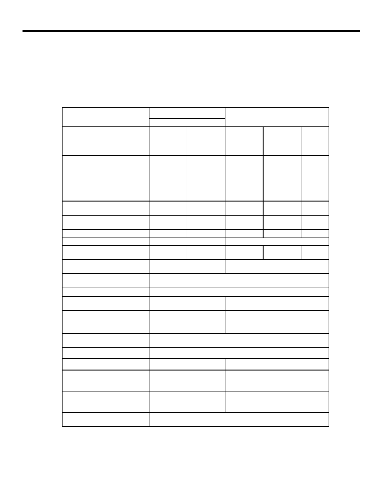
TECHNICAL DATA
HE 620/640BARRIER GATE OPERATOR(S)
T
January, 2007
620/640 Operator And
Parameter
Available beam length, ft (m) 8 (2.5) 10 (3) 13 (4)
10 (3) 13 (4) 16 (5)
13 (4) 16 (5)
Maximum beam length, ft
1
(m)
Wood
Aluminum
Articulated beam
(aluminum only)
Skirted beam
(aluminum only)
Pump capacity, liters 2 1.5 2
Motor speed, rpm 2800
Opening time, sec (not
including braking)
Motor run time
use), %
Power voltage required, VAC
(frequency, Hz)3
Power consumption, W 440
Operator cabinet weight, lb
(kg)
2
(frequency of
13 (4)
12 (3)
10 (3) 13 (4) NA
620
Express
NA NA 16 (5)
2 3 4
100 100
161 (73) 185 (84)
16 (5)
13 (4)
2 1400
230/115 +6 or -10% (50–60)3
16 (5)
16 (5)
640
16 (5) 20 (6)
18 (5.5) 23 (7)
20 (6)
18 (5.5)
20 (6)
NA NA
20 (6) 23 (7)
1.5 1
5.5 8
20 (6)
23 (7)
Operator cabinet dimensions,
in. (cm)
Type of oil Lubrication Engineers- MONOLEC 6115
Oil quantity, qt (l) 2.1 (2)
Fan Standard Standard
Automatic fan operation
temperature, deg F (deg C)
Automatic motor shut off
temperature, deg F (deg C)
Thermal overload switch, deg
F (deg C)
1 Measurements in feet are rounded; measurements in meters are precise.
2 The model 620 115VAC is not available with a 2800 rpm motor.
3 Your standard 220 VAC/115VAC power source meets the specification for 230 VAC, +6 or -10%
6-5/8 ´ 13-3/4 ´ 42-1/2
(17 ´ 35 ´ 108)
113 (45) 113 (45)
185 (85) 185 (85)
7-7/8 ´ 14-15/16 ´ 42-1/2
(20 ´ 38 ´ 108)
212 (100)
Page 5

January, 2007
620/640 Operator And
624BLD Control Panel Installation Manual
UNPACKING THE BARRIER
Page 5
When you receive your Barrier System, complete the
following steps.
Before you remove the barrier beam or cabinet from its
shipping carton, inspect the carton for damage. As you
unpack the carton, insure that all the parts listed below for
your system are included and are undamaged.
Inspect the parts for damage. Notify the carrier immediately
if you note any damage because the carrier must witness the
damage before you can file a claim.
GENERAL CHARACTERISTICS
The U.L. listed Model 620 or 640 Barrier gate system
includes a barrier beam and a cabinet housing the hydraulic
operator and control panel.
The main differences between the 620 and the 640 Barrier
systems are in the length of the barrier beam and in the
speed of operation. The 620 system controls beams that are
6-1/2 to 13 ft (2 to 4.5 m) in length and offers extremely
fast opening and closing times. The 620 is ideal for singlelane vehicular traffic in moderate to heavy traffic. The 620
Barrier can also be articulated (jointed) for use with low
overhead clearances or skirted to prevent vehicles from
passing beneath the beam.
The 640 Barrier system is for barrier beams that are 13 to
23 ft (4 to 7 m) long and is suitable for wide entrances and
heavy-duty applications. The 640 Barrier can also be skirted
(Aluminum Beams Only).
The barrier beam is attached to a heavy-duty, lockable metal
cabinet bolted to a cement foundation. Inside the cabinet
are the operator and the control panel. Important metal
parts of the barrier unit have been powder coated to resist
the effects of rust and smog.
The motor housing holds the oil that drives the pistons and
helps to cool the motor. The temperature of the oil is
monitored, and in high oil temperatures a cooling fan
automatically turns on for further cooling.
The hydraulic motor of either the 620 or 640 operator
drives two single-acting pistons. Both are attached to the
rocker arm, and the rocker arm rotates the barrier beam. A
compression spring attached to one piston serves to
counterbalance the beam, and an adjustable braking feature
guarantees smooth movement of the beam through its
travel and prevents damage to the beam and cabinet from
abrupt stopping.
Some notable features enhance the reliable and safe
operation of the 620 or 640 Barrier. First, a hydraulic
locking device holds the beam in both the opened and
The Parts List
Operator Carton:
1 Operator cabinet
1 Key for cabinet
Bolts for attaching beam to cabinet: 4 or 6,
depending on the barrier and type of beam
Beam Carton (optional):
1 barrier beam
closed positions. Second, the metal cabinet that
houses the operator can be opened only with a key.
Third, the barrier includes a Manual Release function
to disengage the beam from its hydraulic operation
so that you can raise or lower the beam by hand.
Fourth, two adjustable hydraulic valves precisely
control the force of the beam in the opening and
closing directions.
An optional solenoid valve is available for
automatically disengaging the hydraulic system in the
event of power failures.
Both the 620 and 640 Barriers are supplied with the
FAAC 625 BLD Control Panel. The control panel allows
you to select the following:
• Logical mode of operation
• Braking time of the beam
• Pause time between opening and closing
The control panel also provides terminal connections
for a number of other reversing and gate system
accessories.
Furthermore, the control panel provides a number of
light-emitting diodes (LEDs) and a digital display for
easily diagnosing any operational problems.
Page 6
Page 6
January, 2007
620/640 Operator And
624BLD Control Panel Installation Manual
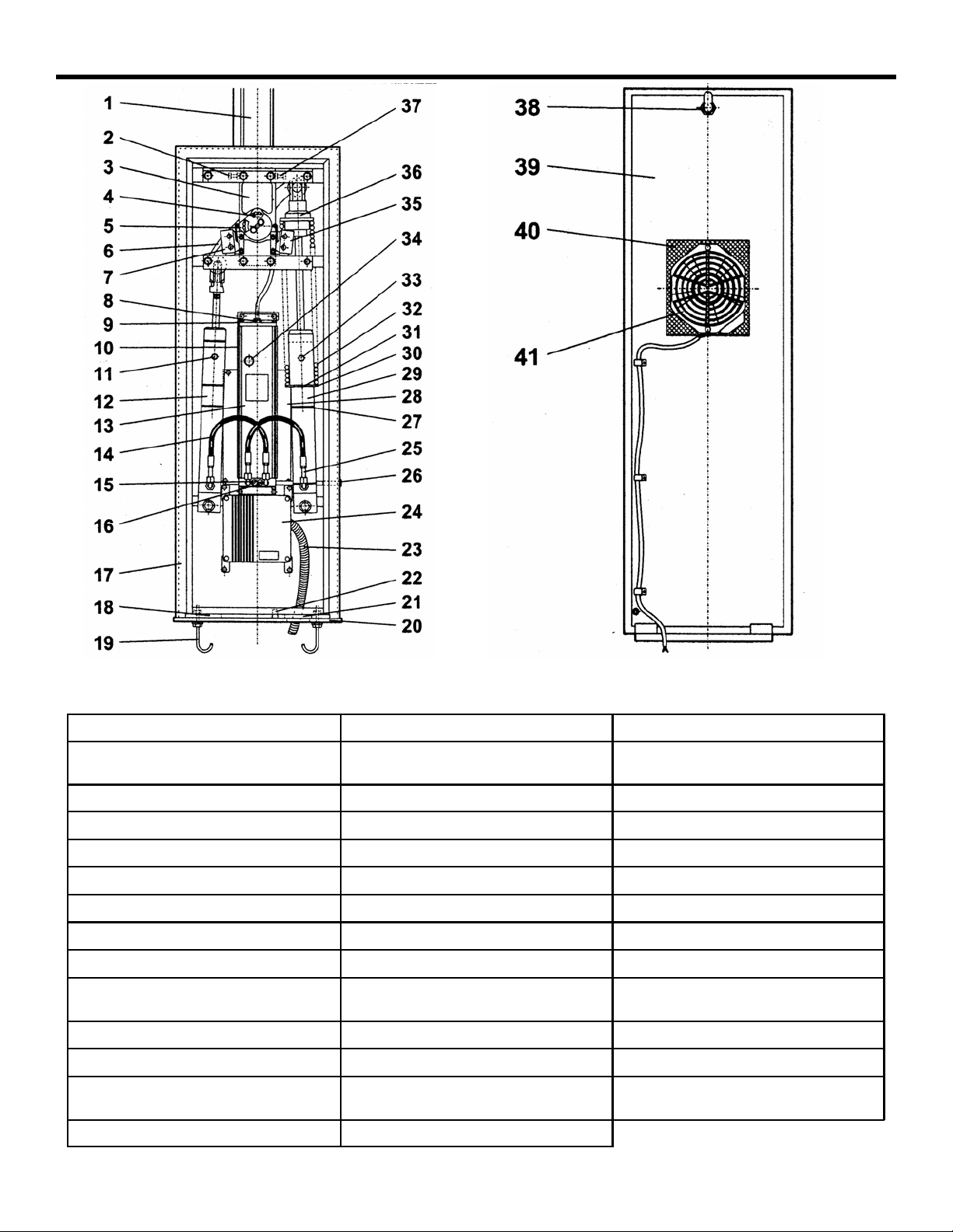
Figure 1. The interior of the 620/640 Barrier cabinet (for right-hand orientation)
1 Aluminum Beam 15 Pressure Adjusting Screw 29 Right Side Piston
2 Left Hand Stop 16 Pressure Adjusting Screw 30 Spring Support (large spring
groove)
3 Rocker Assembly 17 Cabinet 31 Spring Support Ring
4 Right Hand Limit Adjuster 18 Hole for conduit/wire 32 Spring
5 Left Hand Limit Adjuster 19 Anchor Bolt 33 Right Side Piston Bleed Screw
6 Rocker Arm 20 Foundation Plate (Optional) 34 Thermal (On Older Models)
7 Left Side Limit Switch 21 Hole for conduit/wire 35 Right Side Limit Switch
8 Oil Fill Cap 22 Grounding Lug 36 Spring Adjuster Nut
9 Vent Screw 23 Conduit (Not Supplied) 37 Right Hand Stop
10 Cooling Fins (On motor/pump 24 Control Panel Enclosure 38 Lock
11 Left Side Piston Bleed Screw 25 Hydraulic Hose 39 Door
12 Left side Piston 26 Manual Release 40 Screen For Air Intake
13 Motor Pump Assembly 27 Spring Support (small spring 41 Cooling Fan
14 Hydraulic Hose 28 Screen Cover for Air Intake
Page 7
January, 2007
620/640 Operator And
624BLD Control Panel Installation Manual
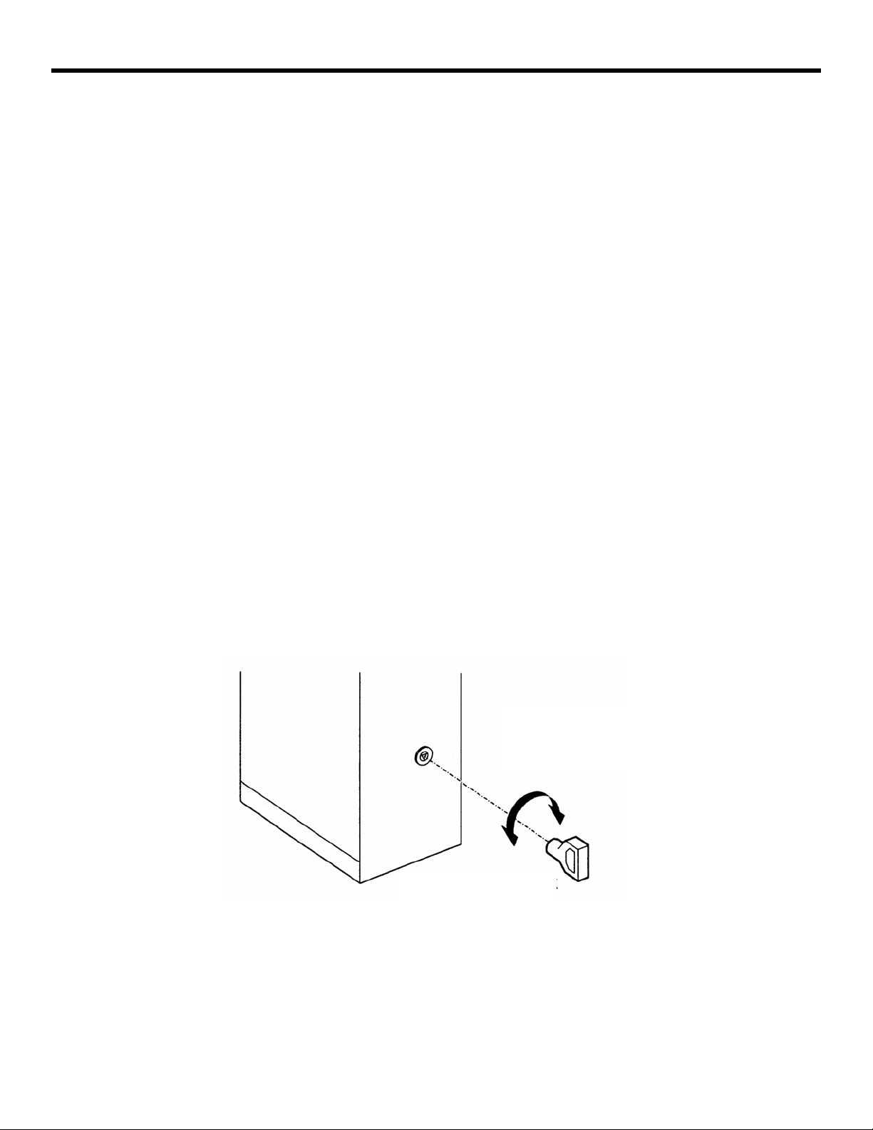
MANUAL RELEASE MECHANISM
WARNING! You must have the manual release
key to access the function of the manual release.
Using any other tools could damage the manual
release mechanism.
The Manual Release function for the 620 or 640 Barrier
is engaged with a key in the operator cabinet on the
lower right side. (See figure 2)
Using the Manual Release key to disengage the beam
from hydraulic operation allows you to operate the
barrier by hand.
You disconnect the hydraulic operation of the beam by
turning the Manual Release key counterclockwise. Then
you can raise or lower the barrier by hand.
Manual operation of the beam is important during the
installation process and can be useful during power
interruptions or power failures.
To re-engage the hydraulic operation of the barrier,
turn the key clockwise until the mechanism is “snug”
tight.
Page 7
AUTOMATIC
(LOCK)
MANUAL
(UNLOCK)
Figure 2. Manual Release Location on both the 620/640 Barrier
Page 8
Page 8
January, 2007
620/640 Operator And
624BLD Control Panel Installation Manual
INSTALLING THE BARRIER
WARNING! Do not install the barrier in such a
way that the beam moves within 2 feet (610
mm) of a rigid object.
Installing the 620 or 640 Barrier System consists of the
following general steps:
• Determining the orientation of the installation
• Preparing the forms for the concrete mounting
slab and conduit
• Mounting the cabinet on the concrete slab
• Connecting the main power source to the
operator
• Wiring the control panel for operational logic
• Wiring additional accessories into the control
panel
• Decreasing the hydraulic pressures
• Programming the control panel
• Attaching the barrier beam
• Testing the operation of the beam
Note: The following installation instructions
assume you are fully capable of installing an
electronic barrier gate. This manual does not
instruct you in designing a gate, pouring the
cement foundation, or basic electrical wiring. The
installation tasks discussed in this manual are
tasks peculiar to the 620 and 640 Barriers.
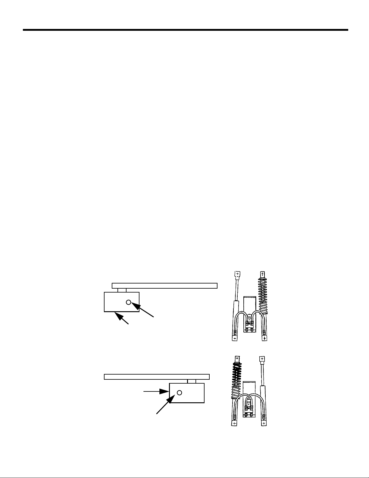
DETERMINE THE ORIENTATION OF THE INSTALLATION
You first need to determine whether your operator is set
up for a right-hand or left-hand installation (see Figure 3).
Open the panel door of the operator cabinet with the key
provided and lift the door up and away from the cabinet,
taking care not to disconnect the cabling to the fan. Look
at the two pistons to see which has the compression
spring surrounding it. Compare your operator with Figure
3 and use the figure to help you determine the orientation
of your installation.
If your operator is not in the correct orientation, turning
the cabinet around 180 deg is the easiest way to solve the
problem. We suggest you call us if your installation site
cannot accommodate this solution since the orientation of
the barrier can be changed with about an hour’s worth of
work.
NOTE: It make no difference if the
hoses are crossed or not.
(a) Right-hand orientation: top view and hose connections
Beam side Beam
Panel
side
Cabinet
Compression
spring
(b) Left-hand orientation: top view and hose connections
Beam
Beam side
Cabinet
Panel
Compression
side
spring
Figure 3. Right Hand vs. Left Hand Installation of the 620/640 Barrier
Page 9
January, 2007
620/640 Operator And
624BLD Control Panel Installation Manual
Page 9
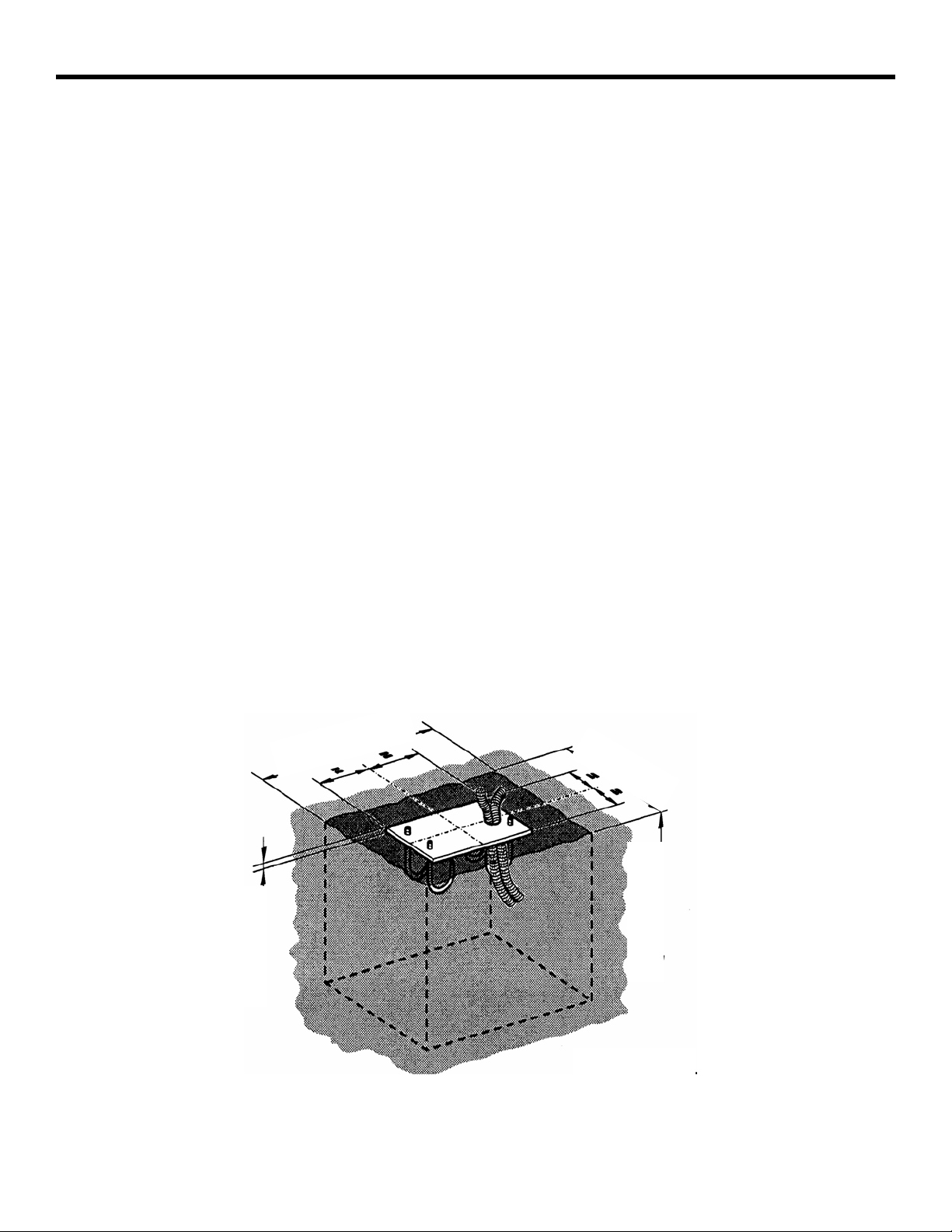
PREPARE THE FORMS FOR THE CONCRETE SLAB AND
C
ONDUIT
You need to set the concrete forms to provide a cement
footing that is a minimum of 18 by 18 in. (46 by 46 cm)
and that is poured a minimum of 18 in. (46 cm) below
the ground level or just below the frost line, whichever
is greater (see Figure 4). (Your soil conditions will also
affect the size of the cement footing.) To help prevent
rust, the top of your cement footing should be above
ground level.
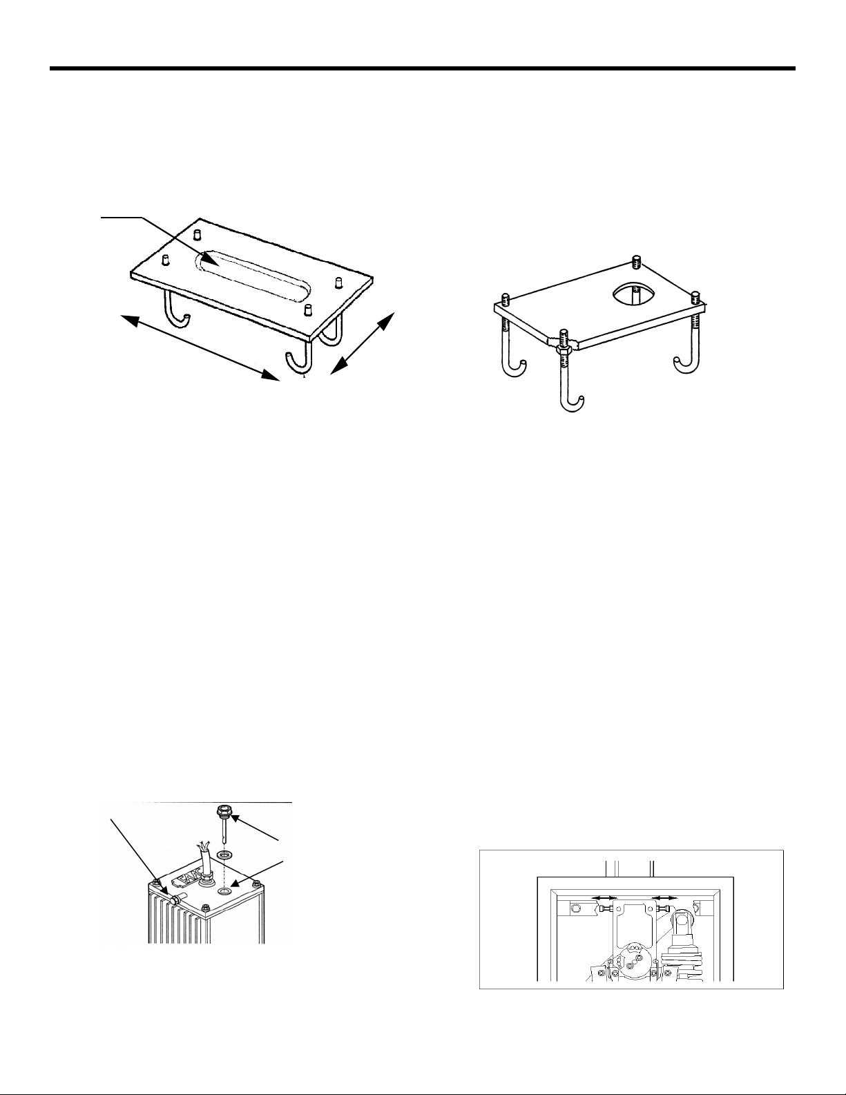
Within the form boundaries you must locate the
electrical conduit so that it will protrude through the
foundation plate (the plate is provided as an option) and
above the top of the foundation plate about
1/2 in. (1.3 cm).
The exact placement of the conduit is determined partly
by the foundation plate you use and more importantly
by the access holes in the bottom of the operator
cabinet (see Figure 5). If you choose to supply your own
foundation plate, be sure to use steel that is 3/8 in. (1
cm) thick for the plate and be sure to provide a hole
large enough to accommodate your two electrical
conduits, one for high-voltage wire and one for lowvoltage wire. In addition, your foundation plate needs
four 1/2-in. (1-1/4 cm) anchor bolts that extend at least
6-1/2 in. (16-1/2 cm) into the cement footing. The
anchor bolts should be positioned to match the holes in
the bottom of your operator's cabinet.
After the concrete is poured in the forms and before it
sets, place the foundation plate in the cement so that the
top of the plate is level and flush with the top of the
cement.
Allow the concrete to set a minimum of two full days
before you mount the operator cabinet.
With the key provided, open the operator's panel door
and lift the door away from the cabinet. It may be
necessary on your model of operator to disconnect the
wiring to the fan on the panel door to allow you to more
easily handle the heavy cabinet.
Set the operator cabinet on the foundation plate, aligning
the holes in the bottom of the cabinet with the bolts and
conduit protruding above the foundation plate. Bolt the
cabinet to the foundation plate and cement footing. If
necessary, reconnect the wiring to the fan on the panel
door.
Before connecting the main power to your barrier, you
must remove the vent screw on the hydraulic power pack.
Midway along the top, left edge of the hydraulic power
pack is a 3 mm Allen screw. Remove it now. Failure to
remove the screw can result in erratic operation of the
barrier beam. Do not throw the screw away in case you
ever need to transport the barrier unit or its hydraulic
power pack.
”
4
2
1/4”
Figure 4. Recommended Concrete Form Dimensions
1
5
”
18”
Page 10
Page 10
January, 2007
620/640 Operator And
624BLD Control Panel Installation Manual
American Style Italian Style
Old Style New Style
A
:
.
E
620 Dimensions 620 Dimensions
A (rectangle): 12 1/16 x 2 1/16 in.
Between bolts
B: 11 1/2 in.
C: 3 1/2 in.
Edge to edge
D: 6 in.
E: 13 3/4 in.
B
C
D
F
G
J
H
Entire plate, edge to edge:
14 1/16 x 7 7/8 in.
Hole diameter: 2 1/4 in.
Distance from hole to edge:
F: 2 3/4 in.
G: 1 1/4 in.
H: 2 3/4 in.
J: 10 5/8 in.
640 Dimensions 640 Dimensions
A (rectangle): 13 3/8 x 3 1/8 in.
Between bolts
B: 12 1/2 in.
C: 5 1/8 in.
Edge to edge
D: 9 in.
E: 15 1/4 in.
Figure 5. FAAC foundation Plates for the 620/640 Barrier
Vent Screw
Location
Oil Fill with Built in
Dipstick
Figure 6. Oil Fill and Vent Screw Locations
Entire plate, edge to edge:
15 1/4 x 9 1/16 in.
Hole diameter: 2 1/4 in.
Distance from hole to edge:
F: 3 1/2 in.
G: 1 1/4 in.
H: 3 1/2 in.
J: 12 in .
Figure 7. Positive Stop Location and Adjusters
Page 11
January, 2007
620/640 Operator And
624BLD Control Panel Installation Manual
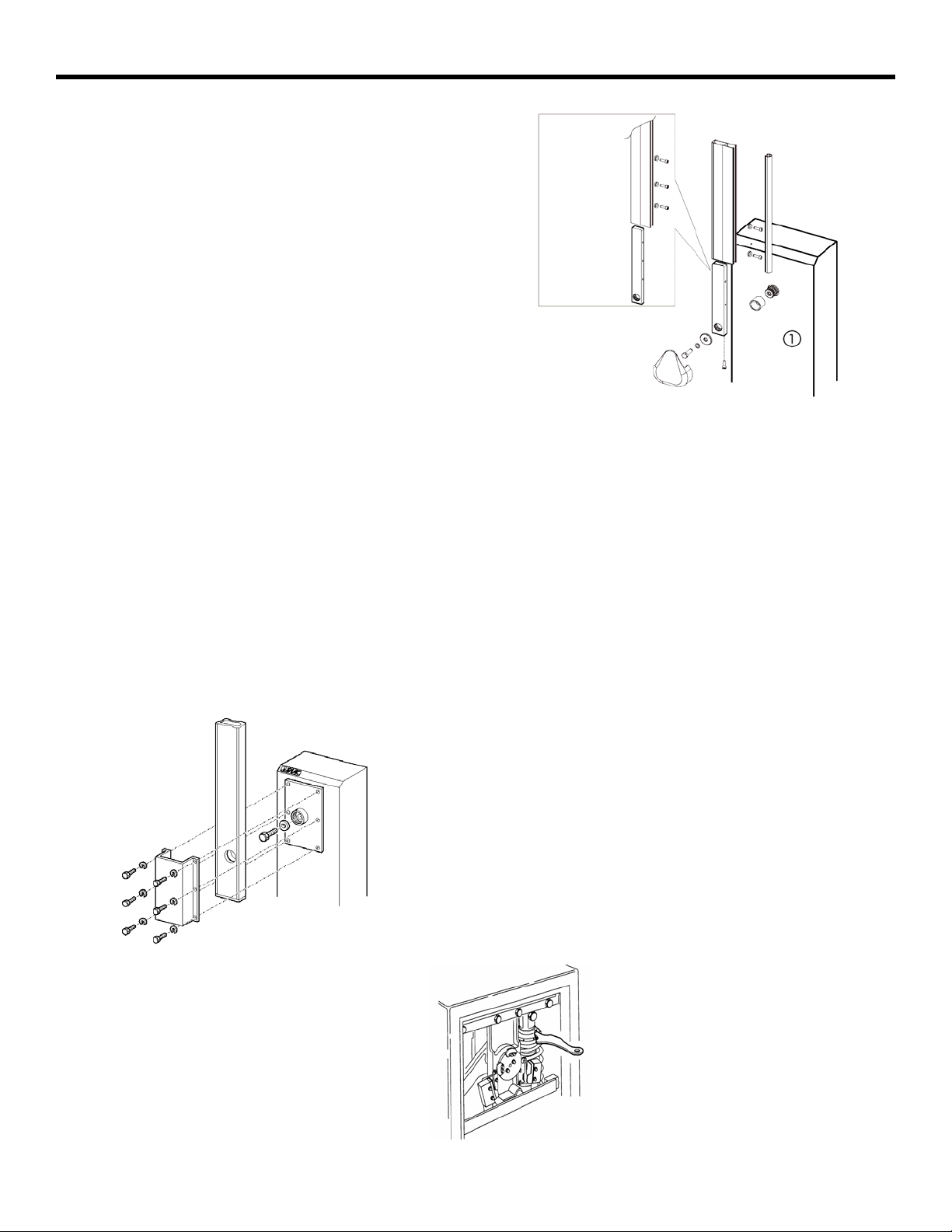
ATTACH THE BARRIER BEAM
WARNING! Do not install the barrier in such a way
that the beam moves within 2 feet (610 mm) of a
rigid object.
Before you attach the barrier beam, be sure you have
disconnected the barrier from hydraulic operation by
means of the Manual Release mechanism (turning the
key counterclockwise).
Next you attach the beam to the operator cabinet with
the beam in a vertical position. See Figure 8 if you are
attaching an aluminum beam to a model 620
operator ,see Figure 9 if you are attaching an aluminum
beam to a model 640 operator. (Wooden beams require
additional sandwich plates).
CHECK THE MECHANICAL STOPS
First, be sure the hydraulic operation of the beam is still
disengaged (the Manual Release key should be turned
counterclockwise). Next, move the beam by hand from
the fully opened position (vertical) to the fully closed
position (horizontal) and back to the fully opened
position. If the positions are not perfectly vertical and
perfectly horizontal, then adjust the mechanical stops
as necessary (see Figure 7) using a 17mm socket
wrench. The jam nut must be loosened first and
tightened last.
640
Page 11
615/620
Figure 8. Beam Attachment 620 (Aluminum Beam)
CHECK THE COMPRESSION SPRING
The compression spring should be adjusted so that it
holds the beam in any position that it is placed while in
manual mode. (Manual mode is discussed on page 7
shown in Fig. 2)
Move the beam by hand to a half-opened position. The
beam should stay there when you remove your hand.
Note: All compression spring adjustments should
be made with the beam in the vertical (open)
position.
If the beam drifts toward the closed position, turn the
adjuster nut (shown in Fig. 10) clockwise to tighten the
compression spring.
If the beam drifts toward the opened position, turn the
adjuster nut (shown in Fig. 10) counterclockwise to
loosen the compression spring.
.
Note: Proper adjustment of the spring will
counterbalance the beam. This will allow the
minimal pressure setting necessary to move the
beam in a smooth movement.
NOTE: The spanner wrench shown in figure 10
is NOT sold by FAAC or needed top make this
adjustment.
Figure 9. Beam Attachment 640 (Aluminum Beam)
Figure 10. Adjuster Nut
Page 12

Page 12
ADJUST THE HYDRAULIC PRESSURES
Now that the beam is attached, re-engage the hydraulic
operation of the barrier by rotating the Manual Release
key clockwise.
Send an opening activating signal to the barrier. The
signal should open the barrier. If it does not open,
increase the pressure of the opening bypass valve (the
green valve) by turning the screw clockwise in small,
1/8- turn increments until the beam does open.
Test the closing of the barrier in the same way. If the
beam fails to move in the closing direction, then
increase the pressure of the closing bypass valve (the
red valve) by turning the screw clockwise in small
increments until the beam does close.
Remember that you should set the bypass pressure
valves so that the beam works with the least pressure
necessary. It is a safety feature of the barrier that the
beam should apply no more than about 33 lb (15 kg)
force against any obstacle it might encounter.
WARNING! For maximum safety to people and
property, use photo eyes and other non-contact
reversing devices in addition to adjusting the
bypass pressure valves to the minimum settings.
INSTALLING THE EMERGENCY BYPASS SOLENOID
AND ANTI-VANDALISM VALVE (230VAC MODELS
O
NLY)
WARNING! Turn the main power off before you
make any electrical connections or set any
switches inside the control panel box.
The emergency bypass solenoid automatically
disengages the hydraulic system of the barrier beam
when the main power is not available. This allows the
barrier to be raised by hand so that people and vehicles
can safely pass during power interruptions and failures
without having to manual release the barrier.
Note: Once the emergency bypass solenoid has
disengaged the hydraulic system and once you
have raised the beam by hand, you cannot lower
the barrier beam until the power is restored or
by using the manual release key.
If you are installing the optional emergency bypass
solenoid, you must first turn off the main power and
disengage the hydraulic system by using the Manual
Release key.
Then you disassemble the hydraulic lines between the
pistons and the operator so that you can install new
hydraulic pipe fittings.
After installing the new pipe fittings, install the
emergency bypass solenoid as shown in figure ()
January, 2007
620/640 Operator And
624BLD Control Panel Installation Manual
After connecting the solenoid, you need to connect the
hydraulic lines between the operator and the pistons.
How you connect the lines depends on the orientation
of your barrier installation (see Figure 11).
Finally, connect the solenoid to your main power line
so that it can sense when power is or is not available
(see Figure 11).
Re-engage the hydraulic system with the Manual
Release key so that you can test the installed solenoid.
To test the solenoid, turn off the power to the barrier. If
the solenoid works, you should be able to raise the
beam but not lower it after raising it. You should be
able to lower the beam only after turning the power
back on.
Figure 11. Emergency By-Pass Valve
and the Anti-Vandalism Valve
Install the anti-vandalism
valve with the instructions
that are provided with it in
it’s packaging.
Page 13

January, 2007
620/640 Operator And
624BLD Control Panel Installation Manual
CHANGING THE LENGTH OR TYPE OF BARRIER
B
EAM
WARNING! Do not install the barrier in such a
way that the beam moves within 2 feet (610 mm)
of a rigid object.
Changing the length or type of the beam requires
installing a different balancing compression spring.
Make sure you have the correct compression spring
(designed for a particular weight of beam).
The installer is responsible for making sure that the
compression spring is the correct spring for the barrier
beam.
The following tables show which springs are designed
for various beam types and lengths. To check for the
part number of the compression spring in your barrier,
check the tag attached to the spring previously
installed.
If it is necessary for you to replace the spring in a
cabinet with another compression spring, do the
following. First, turn off the main power to the operator
and then open the cabinet panel. Turn the Manual
Release key counterclockwise. Then move the beam by
hand to the fully opened position.
Page 13
Unbolt the piston with the compression spring from the
rocker arm. Then very carefully unscrew the cap holding
the compression spring by hand to the left to remove
the spring from the piston. Remove the spring from the
piston.
NOTE: Hold the bottom of the piston cylinder to
keep the piston rod from sliding out of the
cylinder.
Install the correct compression spring by placing it over
the piston and screwing it into place with adjusting cap.
Then bolt the piston to the rocker arm and reinstall the
steel cross member. Re-engage the hydraulics by
turning the Manual Release key clockwise.
Be sure to recheck the tension of the compression
spring before you turn on the main power to the
operator. Then be sure to adjust the hydraulic
pressures.
Rigid Beams: Part Numbers of Compression Springs for Various Lengths
Beam and Required
Spring
Redwood Beam, ft
Rigid Aluminum
Beam, ft (m)
FAAC Part No. for
Compression Spring
Skirted Beams: Part Numbers of Compression Springs for Various Lengths
Beam and Required
Spring
Skirted Aluminum
Beam, ft (m)
FAAC Part No. for
Compression Spring
620 Barrier Systems 640 Barrier Systems
8–10 12–14 16 NA 16–18 18–20 20 NA
6 (2) 8 (2 1/2) 10 (3) 13 (4) 13 (4) 16 (5) 20 (6) 23 (7)
7210855 7210695 7210705 7210885 7210735 7210745 7210755 7210805
620 Barrier Systems 640 Barrier Systems
6 (2) 8 (2 1/2) 10 (3) 13 (4) 13 (4) 16 (5) 20 (6) 23 (7)
7210695 7210715 7210735 7210745 7210795 7210805 7210815 7210825
Page 14

620/640 Operator And
Page 14
624BLD Control Panel Installation Manual
BEAM AND BEAM ACCESSORIES
January, 2007
Assembled Beam Skirt Kit
Recommend aluminum beams only
Figure 13. Articulated beams
ideal for low ceiling heights.
Figure 14. Round Beams
(620 Models Only)
Steps 1-5 for assembly of
Beam Skirt Kit
Figure 12. Skirted Beam Kit and Assembly Instructions.
(The Skirt Kits Are Intended For Aluminum Beams Only)
Figure 15. Break Away
Round Beams
(620 Models Only)
Page 15

January, 2007
620/640 Operator And
624BLD Control Panel Installation Manual
BREAK AWAY BEAM “STOP” SWITCH
Page 15
”
4
/
3
2
12”
2
3
/
4
”
12”
Figure 16. 620 Break Away Round Beam Stop Switch Installation Instruc-
Page 16

Page 16
620 CABINET EXPLODED VIEW
January, 2007
620/640 Operator And
624BLD Control Panel Installation Manual
POS. PART DESCRIPTION QTY
1 N/A FAAC Logo 1
2 N/A 620 Cross Member 2
3 N/A Cross Member Bolt 2
4 N/A Lock Washer (10MM) 8
5 N/A Screen/Filter 1
6* 2022711 624 BLD Control Panel 1
7 416004 620 Cabinet (Orange) 1
8 N/A Washer (4MM) 4
9 N/A Nut (4MM) 16
10 N/A Nut (10MM) 2
11 N/A Positive Stop Bolt
(10x35MM)
12 499460 Rocker Assembly Housing 1
13 N/A Door Gasket 94”
14 2484 Bearing (Output Shaft) 2
15 N/A Output Shaft 1
16 7073015 Ball Joint 2
17 415001 Rocker Arm 1
18 7580145 Limit Switches 2
19 N/A Screw (3x16MM) 4
2
POS. PART
NUMBER
22 N/A Limit Switch Cam Plate 1
23 N/A Lock Washer (6MM) 2
24 N/A Screw (6x10MM) 2
25 N/A Spacer 2
26 N/A Bolt 4
27 N/A Harness (Limit Switches) 1
28 7291025 Lock Dog 1
29 7120505 Key Cylinder 1
30 7131005 Viro Key 10
31 N/A Screen/Filter 1
32 7270645 Cabinet Door 1
33 N/A Wire Loom 9
34 N/A Bolt (10x140MM) 2
35 N/A Cable Clamp 1
36 N/A Harness (Fan) 1
37** N/A Cooling Fan 1
38 N/A Bolt (Allen Head 4x16MM) 2
39 N/A Fan Guard 1
40 N/A Skin Pack 1
DESCRIPTION QTY
20 N/A Bolt (Allen Head 4X10MM) 4
21 N/A Limit Switch Cams 2
* 624 BLD Control Panel 115VAC = 2022712
** Electric Fan 115VAC = 727316
Page 17

January, 2007
620/640 Operator And
624BLD Control Panel Installation Manual
640 CABINET EXPLODED VIEW
Page 17
POS. PART
NUMBER
1 N/A FAAC Logo 1
2 N/A 620 Cross Member 2
3 N/A Cross Member Bolt 2
4 N/A Lock Washer (10MM) 8
5 N/A Screen/Filter 1
6* 2022711 624 BLD Control Panel 1
7 416004 620 Cabinet (Orange) 1
8 N/A Washer (4MM) 8
9 N/A Nut (4MM) 18
10 N/A Nut (10MM) 2
11 N/A Positive Stop Bolt
12 499460 Rocker Assembly Housing 1
13 N/A Door Gasket 102”
14 2484 Bearing (Output Shaft) 2
15 N/A Output Shaft 1
16 7073015 Ball Joint 2
17 416003 Rocker Arm 1
18 7580145 Limit Switches 2
19 N/A Screw (3x16MM) 4
DESCRIPTION QTY
2
(10x35MM)
POS. PART
NUMBER
22 N/A Limit Switch Cam Plate 1
23 N/A Lock Washer (6MM) 2
24 N/A Screw (6x10MM) 2
25 N/A Spacer 2
26 N/A Bolt (10x20MM) 4
27 N/A Harness (Limit Switches) 1
28 7291025 Lock Dog 1
29 7120505 Key Cylinder 1
30 7131005 Viro Key 10
31 N/A Screen/Filter 1
32 7270655 Cabinet Door 1
33 N/A Wire Loom 9
34 N/A Bolt (10x140MM) 2
35 N/A Cable Clamp 1
36 N/A Harness (Fan) 1
37** N/A Cooling Fan 1
38 N/A Bolt (Allen Head 4x16MM) 2
39 N/A Fan Guard 1
40 N/A Skin Pack 1
DESCRIPTION QTY
20 N/A Bolt (Allen Head 4x10MM)) 4
21 N/A Limit Switch Cams 2
* 624 BLD Control Panel 115VAC = 2022712
** Electric Fan 115VAC = 727316
Page 18

Page 18
620 MOTOR PUMP ASSEMBLY
624BLD Control Panel Installation Manual
XPLODED VIEW
E
January, 2007
620/640 Operator And
Page 19

January, 2007
620/640 Operator And
624BLD Control Panel Installation Manual
Page 19
POS PART
NUMBER
101 7221005 Spring Adjustment Fork 1
102 7182155 Shoulder Bolt 4
103 7049145 Spring Adj. Retainer 1
105 7360165 Cylinder Protection Guide 1
106 7222725 Spring Support Ring 1
107 2487 Snap Ring (Spring Support) 1
108 7039285 Washer 8
109 7110115 Banjo Bolt 4
110 N/A Lock Washer 2
111 2274 Screw (Air Bleed) 2
112 N/A Copper Washer 2
113 725202 Piston (Spring Side) 1
114 7073015 Ball Joint 2
115 N/A Harness (Thermal) 1
116 7543005 Temperature Switch 1
DESCRIPTION QTY
POS PART
136 N/A Washer 4
137 702003 Nut (Jam) 4
138* 7700205 Motor 1
139** 3204435 Lobe Pump* 1
140 N/A Fork (Non Spring Cylinder) 1
141 725203 Piston (Non Spring Side) 1
142 N/A Pin (Pump) 2
143 7090010015 O-Ring (Pump to Valve Body) 2
144 4404065 Inlet Valve 2
145 7049005 Retainer 2
146 7090300015 O-Ring (Shuttle Piston) 1
147 4180285 Shuttle Piston 1
148 4404085 Lock Valve 2
149 7049005 Retainer (Brass) 2
150 4997645 Valve Body 1
151 N/A Roll Pin (Manual Release Lock) 1
152 N/A Bolt (Allen Head) 2
DESCRIPTION QTY
NUMBER
117 7361275 Hydraulic Hose 2
118 7039275 Fiber Washer 1
119 7099315 Gasket (Flange) 2
120 7112055 Oil Cap (Dip Stick) 1
121 7043355 O-Ring (Strain Relief) 1
122 N/A Strain Relief 1
123 N/A Screw 4
124 N/A Washer 4
125 7220625 Mounting Bracket 2
126 7099245 Gasket (Strain Relief) 1
127 7270535 Flange (Top) 1
128 2274 Vent Screw 1
129 7094065 Washer 1
130 7230295 Tie Rod 4
131 N/A Star Washer 4
132 N/A Operator Body 1
133 7514075 Power Cord 1
134 N/A Screw 1
135 2365 Bolt (Motor) 4
153 N/A By Pass Valve Feet 2
154 N/A By Pass Valve Spring 2
155 4180395 By Pass Screw 1
156 4180395 By Pass Screw 1
157 7090150015 O-Ring ( By Pass Screws) 2
158 N/A O-Ring (Manual Release) 1
159 4180305 Manual Release 1
160 7090050015 O-Ring (Inlet Valve) 6
161 N/A Roll Pin (Manual Release Rod) 1
162 N/A Coupler (Manual Release Rod) 1
163 7128035 Manual Release Knob
164 424593 Manual Release Assembly 1
165 N/A Wiper Seal 2
166 N/A O-Rings (Cylinder Top) 2
167 7090360025 O-Ring (Piston Center) 2
168 N/A O-Ring (Cylinder Center) 2
169 6115* Artic Grade Oil (Quarts) 2
170 2170* Seal Kit 1
1
(Triangular)
Page 20

Page 20
640 MOTOR PUMP ASSEMBLY
624BLD Control Panel Installation Manual
E
XPLODED VIEW
January, 2007
620/640 Operator And
Page 21

January, 2007
620/640 Operator And
624BLD Control Panel Installation Manual
Page 21
POS PART DESCRIPTION QTY
101 7221005 Spring Adjustment Fork 1
102 7182155 Shoulder Bolt 4
103 7049145 Spring Adj. Retainer 1
105 7360165 Cylinder Protection Guide 1
106 7222725 Spring Support Ring 1
107 2487 Snap Ring (Spring Support) 1
108 7039285 Washer 8
109 7110115 Banjo Bolt 4
110 N/A Lock Washer 2
111 2274 Screw (Air Bleed) 2
112 N/A Copper Washer 2
113 725202 Piston (Spring Side) 1
114 7073015 Ball Joint 2
115 N/A Harness (Thermal) 1
116 7543005 Temperature Switch 1
POS PART DESCRIPTION QTY
136 N/A Washer 4
137 702003 Nut (Jam) 4
138* 7700205 Motor 1
139** 3204435 Lobe Pump* 1
140 N/A Fork (Non Spring Cylinder) 1
141 725203 Piston (Non Spring Side) 1
142 N/A Pin (Pump) 2
143 7090010015 O-Ring (Pump to Valve Body) 2
144 4404065 Inlet Valve 2
145 7049005 Retainer 2
146 7090300015 O-Ring (Shuttle Piston) 1
147 4180285 Shuttle Piston 1
148 4404085 Lock Valve 2
149 7049005 Retainer (Brass) 2
150 4997645 Valve Body 1
151 N/A Roll Pin (Manual Release Lock) 1
152 N/A Bolt (Allen Head) 2
117 7361275 Hydraulic Hose 2
118 7039275 Fiber Washer 1
119 7099315 Gasket (Flange) 2
120 7112065 Oil Cap (Dip Stick) 1
121 7043355 O-Ring (Strain Relief) 1
122 N/A Strain Relief 1
123 N/A Screw 4
124 N/A Washer 4
125 7220625 Mounting Bracket 2
126 7099245 Gasket (Strain Relief) 1
127 7270535 Flange (Top) 1
128 2274 Vent Screw 1
129 7094065 Washer 1
130 7230295 Tie Rod 4
131 N/A Star Washer 4
132 N/A Operator Body 1
133 7514125 Power Cord 1
134 N/A Screw 1
135 2365 Bolt (Motor) 4
153 N/A By Pass Valve Feet 2
154 N/A By Pass Valve Spring 2
155 4180395 By Pass Screw 1
156 4180395 By Pass Screw 1
157 7090150015 O-Ring ( By Pass Screws) 2
158 N/A O-Ring (Manual Release) 1
159 4180305 Manual Release 1
160 7090050015 O-Ring (Inlet Valve) 6
161 N/A Roll Pin (Manual Release Rod) 1
162 N/A Coupler (Manual Release Rod) 1
163 7128035 Manual Release Knob
(Triangular)
164 424593 Manual Release Assembly 1
165 N/A Wiper Seal 2
166 N/A O-Rings (Cylinder Top) 2
167 7090360025 O-Ring (Piston Center) 2
168 N/A O-Ring (Cylinder Center) 2
169 6115* Artic Grade Oil (Quarts) 2
170 2170* Seal Kit 1
1
Page 22

January, 2007
620/640 Operator And
Page 22
624BLD Control Panel Installation Manual
THE 624 BLD CONTROL PANEL
GENERAL DESCRIPTION
The FAAC 624 BLD control panel is used to operate the
following models.
Barrier gate operators:
620 115VAC/230VAC
640 115VAC/230VAC
The 624 BLD programming controls the following:
Operating logic: A, S, E, EP, B, C and other logics.
Reversing device behavior: Choose whether a
triggered reversing device during closing
immediately reverses gate movement or stops the
gate and reverses gate movement when no longer
triggered.
Torque or Pressure: Adjustable from 0 to 50.
Pause time between opening and closing:
adjustable from 0 to 4 minutes.
Opening/Closing time: adjustable from 0 to 4
minutes.
Deceleration Time: programmable
The 624 BLD control panel is installed in an enclosure
that is conveniently located inside the barrier cabinet.
Any addition enclosures should be rated for outdoor
use and be water proof.
The 624 BLD control panel requires a single-phase
power supply voltage (115 VAC [±10%] or 230 VAC [+6
or -10%], 50–60 Hz). The power supply should be
protected by a 15 amp dedicated circuit breaker (not
provided).
The installer is responsible for grounding the
operator system, for providing the main power
breaker switch, and for making sure that the entire
gate system meets all applicable electrical codes.
The installer should refer to the installation manual
for a given operator for more information.
N
OTE: An installation is U.L. compliant only
when you install the FAAC operators according
to the UL325 standards.
INSTALLING THE 624 BLD CONTROL PANEL
Installing the control panel consists of the following
general steps:
• Connecting the main power to the control
panel
• Connecting the activating device
• Connecting the operator to the control panel
• Checking the direction of the motor's rotation
• Connecting other devices to the control panel
• Set operating modes
CONNECT THE MAIN POWER SUPPLY (REPLACEMENT
P
ANELS ONLY)
WARNING! Turn the main power off before you
make any electrical connections or before
programming.
If the panel is installed in the barrier system than the
main power needs to be wired to the switch that is
explained in the barrier section of this manual.
Wire the main power supply to control panel terminals
in block J9 (Figure 1C). The installer is responsible for
insuring that a separate, grounded circuit protected by a
circuit breaker is between the control panel and the
main power supply. All wiring should conform to
applicable electrical codes, and all wiring and fittings
should be weatherproof and/or suitable for burial.
Connect the ground to the grounding terminal in block
J9 and connect the power wires to the terminals labeled
N (neutral) and L (line).
N
OTE: For a 230V system, a neutral is not
needed. Connect one 115V line to the L (Line)
and a second 115V line to the N (Neutral).
THE 624 BLD CONTROL PANEL INSTALLATION INSTRUCTIONS
Page 23

January, 2007
620/640 Operator And
624BLD Control Panel Installation Manual
THE 624 BLD CONTROL PANEL
TECHNICAL SPECIFICATION
Supply Voltage 115/230 VAC (+6% -10%)
Absorbed Power 7 Watts
Accessory Voltage Supplied 24VDC
Fuse Ratings 500mA
Logics A, A1,E,P,PA,CN,CA,RB,C,R,CU
Motor Run Time Programmable (0-4 minutes)
Pause Time Programmable (0-4 minutes)
Motor Power Programmable (50 levels)
Connectors on Board Limit Switches, Loop Detector, Break Away Beam Sensor
Radio Plug In FAAC Plug In Radio Receiver
Page 23
THE 624 BLD CONTROL PANEL INSTALLATION INSTRUCTIONS
Programming Buttons 3 Buttons (+, -, F)
Programming Functions Logics, Pause Time, Work Time, Deceleration Time, Torque, and Loop 1 & 2.
DL Display for Programming/Diagnostics
LED Input Status LEDS (Light Emitting Diodes)
J1 Low Voltage Terminal Strip
J2 Terminal Strip For Motor, Fan, Warning Light
J3 Open Limit Switch Quick Connector
J4 Radio Receiver Plug In
J5 Closing Limit Switch Quick Connector
J6 Break Away Beam Sensor Quick Connector
J8 Capacitor Quick Connector
J9 Main Power Terminal Strip
J11 Loop Detector Quick Connector
Figure 1C. 624 BLD Control Panel
F1 5 Amp (Motor Fuse)
F2 500mA (Accessory Fuse)
F Program Push Button “F”
+ Program Push Button “+”
- Program Push Button “-”
TF1 Transformer
Page 24

Page 24
January, 2007
620/640 Operator And
624BLD Control Panel Installation Manual
Wire other
safeties in
series here
Figure 2C. 624 BLD Board Terminal
Figure 3C. Typical wiring diagram
using FAAC photo beams
(FAAC PART NUMBER 785163).
Wire other reversing devices in
series as shown here.
THE 624 BLD CONTROL PANEL INSTALLATION INSTRUCTIONS
Figure 4C. Typical jumpers needed for
testing purposes.
FAAC Strongly recommends the use of
reversing devices for a safe/UL listed
installation.
Page 25

January, 2007
620/640 Operator And
624BLD Control Panel Installation Manual
CONNECTING THE MAIN POWER SWITCH
The installer is responsible for providing a grounded
circuit protected by a 15 amp circuit breaker from the
main power source to the operator.
N
OTE: Your standard 220VAC/115VAC power
source meets the specification for
230VAC/115VAC, +6 or -10%.
All wiring should conform to applicable electrical codes
and all wiring and fittings should be weatherproof
and/or suitable for burial.
To connect the main power source to the barrier,
remove the cover of the main power switch at the top
of the inside of the barrier cabinet. Then run the main
power wires from the base of the cabinet up through
flexible conduit that is on the cabinet door side of the
steel cross member. Run the wires and conduit through
the connector on the right side of the junction box for
the main power switch.
Page 25
C
AUTION: Do not run the main power conduit up
the metal channel in the right front of the cabinet.
The right front channel houses wiring for the limit
switches and is appropriate only for low-voltage
wiring.
Connect the main power ground wire to the ground
screw in the junction box. Connect the other wires to
the line side of the switch (see Figure 4C). The 624 BLD
control panel is already connected to the load side of
the main power switch.
C
AUTION: U.L. listing requires the use of flexible
conduit around the main power wiring from the
base of the barrier cabinet to the flexible conduit
connector on the junction box of the main power
switch.
THE 624 BLD CONTROL PANEL INSTALLATION INSTRUCTIONS
Connect 230VAC/115VAC
to this side of the switch.
Figure 4C. Main power switch comes to you wired to
the control panel as shown here. The installer must
run wires to the empty side of the switch.
Page 26

Page 26
January, 2007
620/640 Operator And
624BLD Control Panel Installation Manual
J1 TERMINAL STRIP ACCESSORIES
LOOP 1
1-2): use these terminals to connect the loop you
wish to use as a FREE EXIT.
LOOP 2
terminals 3-4): use these terminals to connect the
loop you wish to use as the REVERSE/CLOSE loop.
OPEN
10): this is where your N.O. activation device wire to
pulse the beam open. (e.g.: push-button)
CLOSE
this is where your N.O. closing devises wire to pulse
the beam closed.
FSW
14) The purpose of the closing reversing devices is to
protect the barrier movement area under the beam, by
reversing motion. If the closing safety devices are
activated when the automated system is in open
status they prevent the closing movement.
STOP
refers to any device (e.g.: push-button) which stops
the motion of the barrier.
EMERGENCY
& 10,or 11 or 19) this refers to any switch which, by
being activated in emergency state, opens the barrier
and stops its movement until the contact is restored.
GND
accessories and DC power negative.
24 Vdc
powering 24VDC accessories.
— Power supply to loop 1 (OPEN - terminals
- Power supply to loop 2 (REVERSE/CLOSE -
- “Opening” Command (N.O. - terminal 5 &
N
OTE: To install several opening devices,
connect the N.O. contacts in parallel.
- “Closing” Command (N.O. - terminal 6 & 10):
N
OTE: To install several total opening pulse
generators, connect the N.O. contacts in
parallel.
- Closing Reversing-devices (N.C. - terminal 7 &
N
OTE: To install several closing safety devices,
connect the N.C. contacts in series.
WARNING: If closing safety devices are not
connected, jumper terminals 7 and 14.
- STOP contact (N.C. - terminal 8 & 10): this
N
OTE: To install several STOP devices,
connect the N.C. contacts in series.
WARNING: If stop safety devices are not
connected, jumper terminals 8 and 10.
- EMERGENCY contact (N.C. - terminal 9
WARNING: If emergency safety devices are
not connected, jumper terminals 9 & 10
between.
- (terminals 10-11-19) - Negative contact for
- (terminals 12-13) - Positive contact for
THE 624 BLD CONTROL PANEL INSTALLATION INSTRUCTIONS
WARNING: Max. load of accessories: 500mA.
OUT 1
- Output 1 (terminal 14): the output can be set
to one of the functions described in 2nd level
Programming. The default value is FAILSAFE
OUT 2
- Output 2 (terminal 15): the output can be set
to one of the functions described in 2nd level
Programming. The default value is beam CLOSED
OUT 3
- Output 3 (terminal 16-17): the output can be
set to one of the functions described in 2nd level
Programming. The default value is INDICATOR LIGHT.
Connect 24 Vdc - 3W max. indicator light, if any, to
these terminals, following the instructions in figure 2C.
WARNING: To avoid shorting the system, do
not exceed the indicated power.
OUT 4 - Output 4 (terminal 18): NOT USED AT THIS
TIME
.
.
ERMINAL STRIP - MOTOR - FLASHING LIGHT
J2 T
AND FAN
M (COM - MOT 1 - MOT 2): Motor connection
LAMP (LAMP - COM): Flashing light output (230V~)
FAN (FAN - COM): Fan output (230V/115V)
J8 CONNECTOR — MOTOR CAPACITOR
Rapid connector for connecting the motor thrust
capacitor.
ERMINAL STRIP - POWER SUPPLY
J9 T
PE : Earth connection
N : Power supply 230/115VAC (Neutral)
L : Power supply 230/115VAC (Line)
WARNING: To ensure correct operation, the
board must be connected to earth ground and
an adequate 15Amp breaker upstream of the
barrier.
J3, J5 RAPID CONNECTORS - FOR OPENING AND
C
LOSING LIMIT SWITCHES
Quick-fit connector for connection of the opening (13)
and closing ( J5) limit-switches.
J6 CONNECTOR - BREAKAWAY BEAM SENSOR
Quick-fit connector for breakaway beam (round) sensor
(where present). If this sensor is not being used, leave
the supplied jumper in place.
Page 27

January, 2007
620/640 Operator And
624BLD Control Panel Installation Manual
J11 A, B, C CONNECTOR - QUICK-FIT
C
ONNECTOR FOR FAAC PLUG IN LOOP DETECTOR
Quick-fit connector for connecting the external loopdetector. For adjustment and programming consult the
loop detector instruction.
J4 QUICK-FIT CONNECTOR - FOR FAAC RADIO
R
ECEIVER
If you are using the FAAC two-channel receiver, you will
be able to directly command the automated system’s
OPEN and CLOSE from the radio control.
WARNING: Insert and remove the plug-in
boards ONLY
after cutting power.
PROGRAMMING
To program the 624 BLD control panel, you must access
the “PROGRAMMING” mode.
Programming is in two parts: 1st LEVEL and 2nd LEVEL.
NOTE: Modification of the programming
parameters is immediately effective, whereas
complete memory-storage occurs only on
exiting programming and returning to the view
of the automation status St. If you cut power
to the unit before returning to view the status,
all the programming changes made will be lost.
NOTE: You can return to viewing the status
from any point of programming at any level, by
pressing keys “F” and “—” at the same time.
NOTE: To restore the programming back to
default settings, press keys “+”, “—”, and “F” at
the same time and hold them down for 5
seconds.
1ST LEVEL PROGRAMMING
To access 1ST LEVEL PROGRAMMING, use push-button
F:
• If you press it (and hold it down), the display shows
the name of the first function.
• If you release the push-button, the display shows
the value or parameter of that function, which can
be changed by using the “+” and/or “—” keys.
• If you press F again (and hold it down) the display
shows the name of the next function, etc.
• When you reach the last function, press the F push-
button to exit programming, and the display
resumes showing the input status.
Page 27
THE 624 BLD CONTROL PANEL INSTALLATION INSTRUCTIONS
The following table indicates the sequence of
functions accessible in 1st LEVEL PROGRAMMING:
1ST LEVEL PROGRAMMING
DISPLAY FUNCTION DEFAULT
FUNCTION LOGICS:
AUTOMATIC
AUTOMATIC 1
SEMI-AUTOMATIC
PARKING
PARKING AUTOMATIC
CONDO
CONDO AUTOMATIC
TRAFFIC BOLLARD LOGIC
DEAD-MAN
REMOTE
CUSTOM
PAUSE TIME:
This function only works if an
automatic logic was selected. It
can be adjusted from 0 to 59
seconds in one second steps.
Next, the viewing changes in
minutes and tenths of a second
(separated by a dot) and time is
adjusted in 10 second steps, up
to the maximum value of 4.1
minutes.
E.g. if the display shows 2.5, the
pause time will be 2 minutes
and 50 seconds.
POWER:
Adjusts motor power.
= minimum power
= maximum power
Page 28

Page 28
January, 2007
620/640 Operator And
624BLD Control Panel Installation Manual
1ST LEVEL PROGRAMMING continued
DISPLAY FUNCTION DEFAULT
LOOP 1:
If this function is activated, the
loop connected to the Loop1
input will have the OPEN
function.
= loop1 active
= loop1 not active
ATTENTION: If the function is
not activated, loop1 status will
nevertheless be available on one
of the outputs, if appropriately
set (see 2nd level programming).
LOOP 2:
If you activate this function, the
loop connected to Loop 2 input
will have the REVERSE/CLOSE
function, i.e. it will operate as
REVERSING during the closing
stage, and will activate a CLOSE
to the board at release.
= loop 2 active
= loop 2 not active
ATTENTION: If the function is
not activated, loop2 status will
nevertheless be available on one
of the outputs, if appropriately
set.
DISPLAY FUNCTION DEFAULT
AUTOMATED SYSTEM STATUS:
1ST LEVEL PROGRAMMING continued
Exit from programming, storage
of set data and return to
automated system status view.
CLOSED
OPENING PRE-FLASHING
OPENING
OPEN
ON PAUSE
CLOSING PRE-FLASHING
CLOSING
STOPPED READY TO
CLOSE
STOPPED READY TO
OPEN
EMERGENCY OPENING
CLOSING SAFETY DEVICE
IN OPERATION
NO EFFECT
NO EFFECT
THE 624 BLD CONTROL PANEL INSTALLATION INSTRUCTIONS
Page 29

January, 2007
620/640 Operator And
624BLD Control Panel Installation Manual
Page 29
THE 624 BLD CONTROL PANEL INSTALLATION INSTRUCTIONS
2ND LEVEL PROGRAMMING
To access 2nd LEVEL PROGRAMMING, press pushbutton F and, while holding it down, press pushbutton “+”.
• If you release the push-button “+”, the display
shows the name of the first function.
• If you also release the F push-button, the display
shows the value or parameter of that function,
which can be changed with the “+” and”—” keys.
• If you press the F key again (and hold it down),
the display shows the name of the next function,
etc.
• When you reach the last function, press the F
push-button to exit programming, and the
display resumes showing the input status.
The following table indicates the sequence of
functions accessible in 2nd LEVEL PROGRAMMING.
2ND LEVEL PROGRAMMING
DISPLAY FUNCTION DEFAULT
MAXIMUM TORQUE AT THRUST:
The motor works at maximum
torque (ignoring the torque
adjustment) during the initial
time of the movement.
= Active
= Excluded
PRE-FLASHING:
To activate the flashing light for
5 sec before the start of the
movement
Excluded
Before every movement
Before closing
At end of pause only
SLOW CLOSING:
For setting the entire closing
stage at slow speed.
= Active
= Excluded
DECELERATION TIME AFTER
LIMIT-SWITCHES:
For setting deceleration time (in
seconds) after the opening and
closing limit-switches have been
activated. It can be adjusted from
0 to 10 sec, in one second steps.
= deceleration excluded
= maximum deceleration
WORK TIME (time out):
We advise you to set a value from
5 to 10 seconds longer than the
required by the automated
system to move from the closing
to the opening position and vice
versa. It can be adjusted from 0
to 59 sec in one second steps.
Next, the viewing changes in
minutes and tenths of a second
(separated by a dot) and time is
adjusted in 10 second steps, up
to the maximum value of 4.1
minutes.
Page 30

Page 30
January, 2007
620/640 Operator And
624BLD Control Panel Installation Manual
2ND LEVEL PROGRAMMING continued
DISPLAY FUNCTION DEFAULT
FAIL SAFE:
If this function is activated, it
enables a function test of the
photocells before any automated
system movement, independently
from the output used. If the test
fails, the automated system does
not start the movement.
= Active
= Excluded
OUTPUT 1:
The output can be set to one of
the following functions:
FAILSAFE
INDICATOR LIGHT
(lighted at opening and
pause, flashing at
closing, and off when
automated system
closed)
BEAM LIGHT (output
achieve with beam closed
and on pause, inactive
with beam open, flashing
during movement)
BEAM CLOSED
BEAM OPEN or in PAUSE,
it goes OFF during
closing pre-flashing
BEAM MOVING AT
OPENING, pre-flashing
included
BEAM MOVING AT
CLOSING, pre-flashing
included
BEAM STILL
BEAM IN EMERGENCY
STATUS
LOOP 1 ENGAGED
LOOP 2 ENGAGED
OPEN FOR 624 SLAVE
CLOSE FOR 624 SLAVE
THE 624 BLD CONTROL PANEL INSTALLATION INSTRUCTIONS
BEAM DETACHED
DISPLAY FUNCTION DEFAULT
OUTPUT 1 POLARITY:
OUTPUT 2:
OUTPUT 2 POLARITY:
OUTPUT 3:
OUTPUT 3 POLARITY:
OUTPUT 4:
OUTPUT 4 POLARITY:
ASSISTANCE REQUEST (work with
2ND LEVEL PROGRAMMING continued
For configuring the output
polarity status.
= N.C. polarity
= N.O. polarity
NOTE: If the output is set to
FAIL-SAFE (00) leave the default
value.
See output 1
See Output 1 Polarity.
See output 1
See Output 1 Polarity.
See output 1, except to functions
00, 11, 12 that in this case have
no effect.
For configuring the output
polarity status.
= Active
= Excluded
the next two functions):
If activated at the end of the
count-down (settable with the
next two functions under “Cycle
Programming”), it activates LAMP
output for 4 sec every 30 sec.
Can be useful for setting
scheduled maintenance.
= Active
= Excluded
Page 31

January, 2007
620/640 Operator And
624BLD Control Panel Installation Manual
Page 31
2ND LEVEL PROGRAMMING continued
DISPLAY FUNCTION DEFAULT
CYCLE PROGRAMMING IN
THOUSANDS:
For setting a count-down of the
system operating cycles. Settable
value from 0 to 99 (thousands of
cycles). The displayed value is
reset as the cycles progress,
interacting with the nC value (99
nc decrementing steps
correspond to one nC
LEDS DESCRIPTION
The following table shows the status of the LEDs in
relation to the status of the inputs (the normal
operating leds are in bold).
Check the status of the signaling LEDs as per table
below:
NOTE: LED on = closed contact
LED off = open contact
Operation of status signaling LEDs
decrement).
The function can be used
combined with nC, to check the
LED Description
use of the system and to make
use of the “Assistance Request”.
CYCLE PROGRAMMING IN
HUNDREDS OF THOUSANDS:
DL1 OPEN Command enabled
DL2 CLOSE Command enabled
For setting a count-down of the
system operating cycles. Settable
value from 0 to 99 (hundreds of
DL3 FSW
thousands of cycles). The
displayed value is reset as the
cycles progress, interacting with
DL4 STOP
the nc value (1 decrement of nC
corresponds to 99 decrements of
DL5 EMERGENCY
nc).
The function can be used
combined with nc to check the
DL6 FCA
use of the system and to make
use of the “Assistance Request”.
NO EFFECT
DL7 FCC
DL8 PIVOT
ON
(closed contact)
Safety devices
released
Command
disabled
Command
disabled
Opening limit
switch free
Closing limit switch
free
Beam attached
THE 624 BLD CONTROL PANEL INSTALLATION INSTRUCTIONS
OFF
(open contact)
Command
disabled
Command
disabled
Safety devices
engaged
Command enabled
Command enabled
Opening limit
switch engaged
Closing limit
switch engaged
Beam detached
NO EFFECT
AUTOMATED SYSTEM STATUS:
Exit from programming, storage
of data and return to gate status
view.
AUTOMATED SYSTEMS TEST
When you have finished programming, check if the
system is operating correctly.
Above all, check, if power is adequately adjusted and if
the reversing devices are operating correctly.
Page 32

Page 32
MASTER/SLAVE WIRING INSTRUCTIONS
To wire two barriers as a Master/Slave
configuration, follow the wiring diagram
below and program the barriers as follows.
MASTER: Program the logic as needed and
the parameters as follows:
OUT2:
OUT3:
SLAVE: Program the slave logic into the “C”
Mode it should look as follows:
= =
= =
=
January, 2007
620/640 Operator And
624BLD Control Panel Installation Manual
Logic
Figure 5C. 624 BLD Master/Slave Wiring
Diagram
THE 624 BLD CONTROL PANEL INSTALLATION INSTRUCTIONS
Page 33

January, 2007
620/640 Operator And
624BLD Control Panel Installation Manual
PROGRAMMING NOTES
Page 33
Page 34

Page 34
January, 2007
620/640 Operator And
624BLD Control Panel Installation Manual
MAINTENANCE
REGULAR MAINTENANCE
Inspect and service your 620 or 640 Barrier system
anytime you observe or suspect a malfunction of the
barrier. In addition, FAAC recommends you check the
barrier system every 1,000,000 cycles of the operator for
the items listed below to keep your operator in the best
working condition. Failure to observe these
recommendations could compromise the functionality of
the operator.
Item to Check Every
1,000,000 Cycles
Entire barrier system Replace any visually
Oil level Refill the oil if necessary
Bypass valves Tighten or loosen the
Beam motion Adjust the compression
What to Do
obvious defective part
valves to maintain the
recommended pressure
settings
spring if necessary
SPECIAL MAINTENANCE
Inspect and service your 620 or 640 Barrier system
anytime you observe or suspect a malfunction of the
barrier. In addition, if your observations warrant it,
FAAC recommends you make the following listed repairs
and replacements to the barrier system to keep your
operator in the best working condition. Failure to
observe these recommendations could compromise the
functionality of the operator.
Part(s) to Repair or Replace Number of
Cycles
Drive pistons:
seals and gaskets
Ball joints in the rocker arm 1,000,000
Mechanical stops 1,000,000
Hydraulic unit:
seals and gaskets
Cooling fan 2,000,000
1,000,000
2,000,000
Cooling fan Clean the motor cooling
ducts
Control panel Test the function of input
power and output function
of all attached relays, cards,
and devices
Balancing spring 3,000,000
Limit switches 6,000,000
Page 35

January, 2007
620/640 Operator And
624BLD Control Panel Installation Manual
Page 35
TROUBLESHOOTING
WARNING! Before you do any work on the control panel, be sure to
turn off the main power.
NOTE: Any control panel specific information in the following applies to the 624BLD control panel only.
PROBLEM:
The beam is closed and won't open in
to an activating signal.
SOLUTION:
Make sure the hydraulic operation of the barrier beam
is engaged: The Manual Release key should be turned
clockwise until snug.
The OPEN indicator LED should illuminate when you
send an activating signal. If it does not, temporarily
short terminals 5 and 10. If the short causes the beam
to open, then the problem exists in the activating
device itself.
If you have no stop device wired to terminal 8, then
make sure you have a jumper installed between
terminals 8 and 10 on the control panel. The STOP LED
should be on.
The FCC indicator light on the control panel should not
be illuminated. If it is illuminated, then the gate is not
fully closed. Adjust the position of the closing limit
switch plate.
Try increasing the opening hydraulic pressure in small
increments by turning the opening bypass valve screw
(the green valve) clockwise.
Verify that you have the correct compression spring
for your barrier beam. If you have the correct spring,
check that the spring will hold the beam in any
position during manual operation. If the spring doesn't
hold the beam in any position, try tightening the
compression spring until the beam is held and then
recheck the hydraulic operation of the beam.
PROBLEM:
The beam is open and won't close in response to an
activating signal.
SOLUTION:
Check the LEDs on the control panel. The FCA light
should be off, and the FSW, STOP, FCC, and
response
EMERGENCY lights should be on if the FCA light is on,
then the gate is not fully opened. Move the opening limit
switch plate closer to the opening limit switch
.
If you have no reversing devices installed and you are
operating in A or E mode, make sure you have a jumper
installed between terminals 7 and 19. (The FSW light
should be on.)
If the FSW light is off, some reversing device you have
installed is being continuously triggered and is preventing
the beam from closing. Check your reversing devices.
If your activating device has two buttons—one for
opening/closing and one for stop—and you are operating
in P mode, then make sure you have a jumper between
terminals 2 and 5.
If you have no stop device wired to terminal 8, then make
sure you have a jumper installed between terminals 8 and
10 on the control panel.
If you have no emergency device wired to terminal 9, then
make sure you have a jumper installed between terminals
9 and 10 on the control panel.
Increase the pressure of the closing bypass valve (the red
valve) by turning the screw clockwise in small increments
to see if the beam needs more hydraulic pressure for the
closing direction.
PROBLEM:
The beam is half opened and will neither open nor
close in response to the activating device.
SOLUTION:
The barrier may be in jam status because something or
someone has physically prevented the beam from
opening or closing. Reset the barrier and then try sending
another activating signal.
Check the FSW indicator light. It should be on. If it is not
illuminated, then check the wiring on your safety devices.
Page 36

January, 2007
620/640 Operator And
624BLD Control Panel Installation Manual
LIMITED WARRANTY
Page 36
To the original purchaser only: FAAC International,
Inc., warrants, for twenty-four (24) months from the
date of invoice, the gate operator systems and other
related systems and equipment manufactured by FAAC
S.p.A. and distributed by FAAC International, Inc., to be
free from defects in material and workmanship under
normal use and service for which it was intended
provided it has been properly installed and operated.
FAAC International, Inc.'s obligations under this
warranty shall be limited to the repair or exchange of
any part of parts manufactured by FAAC S.p.A. and
distributed by FAAC International, Inc. Defective
products must be returned to FAAC International, Inc.,
freight prepaid by purchaser, within the warranty
period. Items returned will be repaired or replaced, at
FAAC International, Inc.'s option, upon an examination
of the product by FAAC International, Inc., which
discloses, to the satisfaction of FAAC International, Inc.,
that the item is defective. FAAC International, Inc. will
return the warranted item freight prepaid. The products
manufactured by FAAC S.p.A. and distributed by FAAC
International, Inc., are not warranted to meet the
specific requirements, if any, of safety codes of any
particular state, municipality, or other jurisdiction, and
neither FAAC S.p.A. or FAAC International, Inc., assume
any risk or liability whatsoever resulting from the use
thereof, whether used singly or in combination with
other machines or apparatus.
Any products and parts not manufactured by FAAC
S.p.A. and distributed by FAAC International, Inc., will
carry only the warranty, if any, of the manufacturer. This
warranty shall not apply to any products or parts thereof
which have been repaired or altered, without FAAC
International, Inc.'s written consent, outside of FAAC
International, Inc.'s workshop, or altered in any way so
as, in the judgment of FAAC International, Inc., to affect
adversely the stability or reliability of the product(s) or
has been subject to misuse, negligence, or accident, or
has not been operated in accordance with FAAC
International, Inc.'s or FAAC S.p.A.'s instructions or has
been operated under conditions more severe than, or
otherwise exceeding, those set forth in the
specifications for such product(s). Neither FAAC S.p.A.
or FAAC International, Inc., shall be liable for any loss or
damage whatsoever resulting, directly or indirectly,
from the use or loss of use of the product(s). Without
limiting the foregoing, this exclusion from liability
embraces a purchaser's expenses for downtime or for
making up downtime, damages for which the purchaser
may be liable to other persons, damages to property,
and injury to or death of any persons. Neither FAAC
S.p.A. or FAAC International, Inc., assumes nor
authorizes any person to assume for them any other
liability in connection with the sale or use of the
products of FAAC S.p.A. or FAAC International, Inc. The
warranty hereinabove set forth shall not be deemed to
cover maintenance parts, including, but not limited to,
hydraulic oil, filters, or the like. No agreement to replace
or repair shall constitute an admission by FAAC S.p.A. or
FAAC International, Inc., of any legal responsibility to
effect such replacement, to make such repair, or
otherwise. This limited warranty extends only to
wholesale customers who buy directly through FAAC
International, Inc.'s normal distribution channels. FAAC
International, Inc., does not warrant its products to end
consumers. Consumers must inquire from their selling
dealer as to the nature and extent of that dealer's
warranty, if any.
This warranty is expressly in lieu of all other
warranties expressed or implied including the warranties of merchantability and fitness for use. This
warranty shall not apply to products or any part
thereof which have been subject to accident, negligence, alteration, abuse, or misuse or if damage was
due to improper installation or use of improper
power source, or if damage was caused by fire, flood,
lightning, electrical power surge, explosion, wind
storm, hail, aircraft or vehicles, vandalism, riot or
civil commotion, or acts of God.
FAAC International, Inc.
303 Lexington Avenue
Cheyenne, WY 82007
www.faacusa.com
 Loading...