

Page 1

T HE 390 24V OPERATOR AND
July, 2006
390 24v Operator And
425 D Control Panel
Installation Manual
425 D C
NSTALLATION MANUAL
I
ONTROL PANEL:
CONTENTS
Important Safety Information 2
Technical Data 4
Unpacking the Operator 5
The 390 24V Operator General Characteristics 6
Installation Instructions 6
Prepare the Gate 6
Manual Release Mechanism 6
Install the Operator 7
Mounting Dimensions 7
Mounting the Base Plate 7
390 Limit Switch Instructions 10
Exploded View, 390 24V Operator 12
390 24V Operator Parts List 13
The 425 D Control Panel
Maintenance 21
Safety in Gate Design 21
Troubleshooting 22
Limited Warranty 24
The 425 D Control Panel General Description 14
Installing the 425 D Control Panel 14
Connect the Main Power Supply 14
Connect the Operator to the Control Panel 14
Connect Accessory Devices 15
Set Operating Modes 16
Setting the DIP Switches 17
Obstacle Recognition 17
Programming 19
Display Descriptions 20
Programming the Motor Run Time 20
Installation Instructions
Fuse Ratings 20
FAAC International, Inc.
303 Lexington Avenue
Cheyenne, WY 82007
www.faacusa.com
Page 2

July, 2006
Page 2
425 D Control Panel Installation Manual
390 24v Operator And
IMPORTANT SAFETY INFORMATION
Both the installer and the owner and/or operator of this
system need to read and understand this installation
manual and the safety instructions supplied with other
components of the gate system. This information
should be retained by the owner and/or operator of the
gate.
WARNING! To reduce the risk of injury or death
1. READ AND FOLLOW ALL
INSTRUCTIONS.
2. Never let children operate or play with gate
controls. Keep the remote control away from
children.
3. Always keep people and objects away from
the gate. NO ONE SHOULD CROSS THE
PATH OF THE MOVING GATE.
4. Test the gate operator monthly. The gate
MUST reverse on contact with a rigid object
or stop when an object activates the noncontact sensors. After adjusting the force or
the limit of travel, retest the gate operator.
Failure to adjust and retest the gate operator
properly can increase the risk of injury or
death.
5. Use the emergency release only when the
gate is not moving.
6. KEEP GATES PROPERLY MAINTAINED. Read
the owner’s manual. Have a qualified service
person make repairs to gate hardware.
7. The entrance is for vehicles only. Pedestrians
must use separate entrance.
8. SAVE THESE INSTRUCTIONS.
When installing the photo-beams supplied with this
unit two things need to be considered.
1. Care should be exercised to reduce the risk of
nuisance tripping, such as when a vehicle, trips
the sensor while the gate is in motion.
2. One or more photobeams shall be located
where the risk of entrapment exists, such as
the perimeter reachable by the moving gate
leaf.
GATE DESIGN
1. A gate is a potential traffic hazard, so it is important that you locate the gate far enough away
from the road to eliminate the potential of traffic
getting backed up. This distance is affected by the
size of the gate, how often it is used, and how fast
the gate operates.
2. The operator you choose to install on your gate
must be designed for the type and size of your gate
and for the frequency with which you use the
operator.
3. Your gate must be properly installed and must work
freely in both directions before the automatic
operator is installed.
4. An automatic operator should be installed on the
inside of the property/fence line. Do not install the
operator on the public side of the property/fence
line.
5. Pedestrians should not use a vehicular gate system.
Prevent such inappropriate use by installing
separate gates for pedestrians.
6. Exposed, reachable pinch points on a gate are
potentially hazardous and must be eliminated or
guarded.
7. Outward swinging gates with automatic operators
should not open into a public area.
8. The operating controls for an automatic gate must
be secured to prevent the unauthorized use of those
controls.
9. The controls for an automatic gate should be
located far enough from the gate so that a user
cannot accidentally touch the gate when operating
the controls.
10. An automatic gate operator should not be installed
on a gate if people can reach or extend their arms
or legs through the gate. Such gates should be
guarded or screened to prevent such access.
INSTALLATION
1. If you have any question about the safety of the
gate operating system, do not install this operator.
Consult the operator manufacturer.
2. The condition of the gate structure itself directly
affects the reliability and safety of the gate
operator.
3. Only qualified personnel should install this
equipment. Failure to meet this requirement could
cause severe injury and/or death, for which the
manufacturer cannot be held responsible.
4. The installer must provide a main power switch that
meets all applicable safety regulations.
5. Clearly indicate on the gate with the 2 warning signs
that are included (visible from either side of the
gate).
Page 3

July, 2006
390 24v Operator And
425 D Control Panel Installation Manual
Page 3
6. It is extremely unsafe to compensate for a damaged
gate by increasing hydraulic pressure.
7. Devices such as reversing edges and photobeams
must be installed to provide better protection for
personal property and pedestrians. Install reversing
devices that are appropriate to the gate design and
gate application.
8. Before applying electrical power, be sure that the
voltage requirements of the equipment correspond
to your supply voltage. Refer to the label on your
operator system.
USE
1. Use this equipment only in the capacity for which it
was designed. Any use other than that stated should
be considered improper and therefore dangerous.
2. When using any electrical equipment, observe some
fundamental rules:
• Do not touch the equipment with damp or
humid hands or feet.
• Do not install or operate the equipment
with bare feet.
• Do not allow small children or incapable
persons to use the equipment.
3. If a gate system component malfunctions, turn off
the main power before making any attempt to repair
it.
4. Do not attempt to impede the movement of the
gate. You may injure yourself as a result.
5. This equipment may reach high temperatures
during operation; therefore, use caution when
touching the external housing of the operator.
6. Learn to use the manual release mechanism
according to the procedures found in this installation manual.
7. Before carrying out any cleaning or maintenance
operations, disconnect the equipment from the
electrical supply.
8. To guarantee the efficiency of this equipment, the
manufacturer recommends that qualified personnel
periodically check and maintain the equipment.
U.L. CLASS AND FAAC OPERATOR
Model
Class I: Residential Vehicular Gate Operator
390 750
422 760
415 400
620 640
885 402
Class II: Commercial/General Access Vehicular Gate Operator
400 640
620 885
Class III: Industrial/Limited Access Vehicular Gate Operator
400 640
620 885
Class IV: Restricted Access Vehicular Gate Operator
Duty Cycle Typical Use
• Home use
• Small apartment building, for
Limited duty
Continuous duty
Continuous duty
example, up to 4 units in a
building, with limited public
access
• Apartment buildings
• Very public access
• No public access
620 640
885
Continuous duty
• Prison rated security
Page 4
Page 4
THE 390 OPERATOR
July, 2006
390 24v Operator And
425 D Control Panel Installation Manual
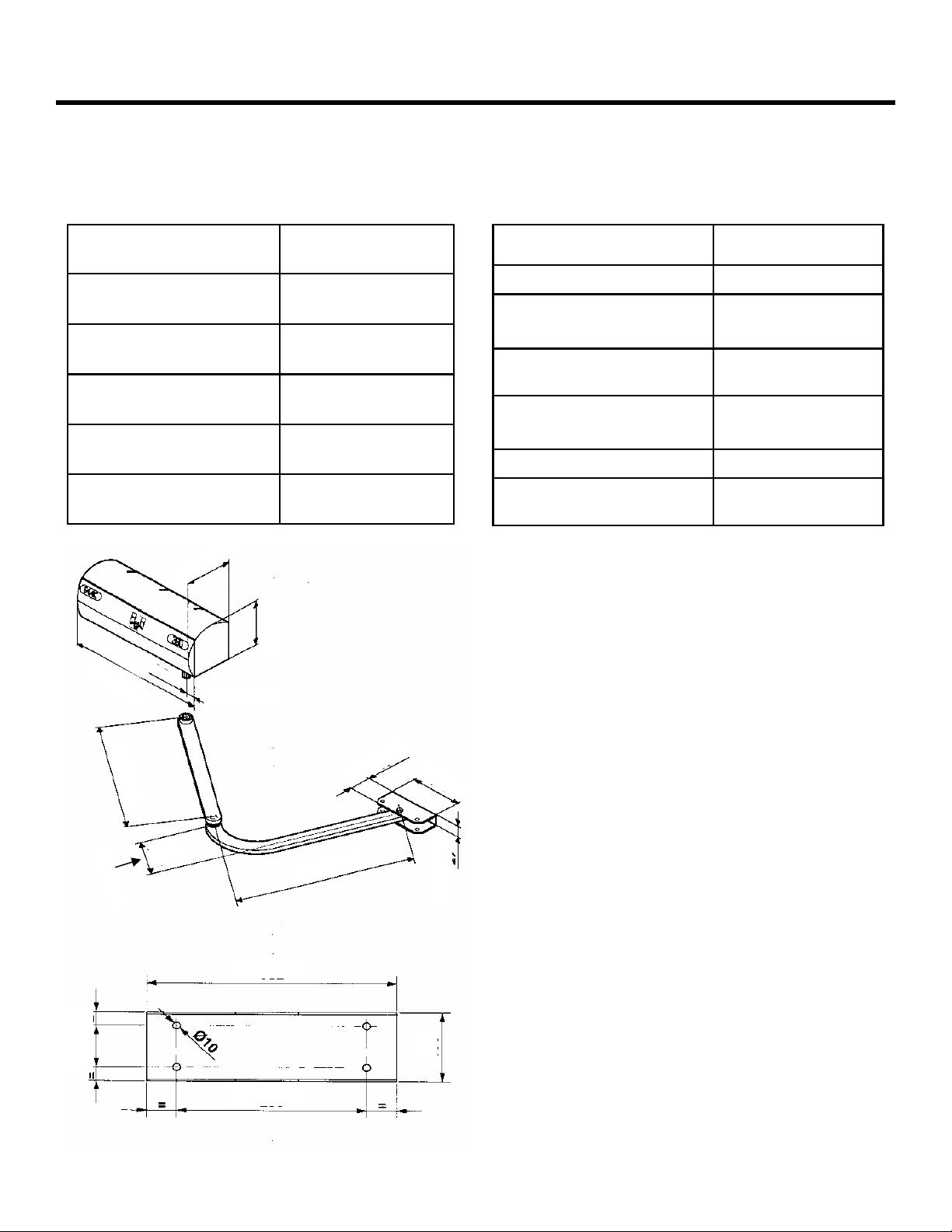
TECHNICAL DATA
Parameter Measure
Voltage required, VDC 24 Vdc
Duty type Residential
Maximum duty cycle 100%
Maximum leaf length, ft
14 (3)
(m)
Maximum leaf swing, deg 120
“
8
/
1
5
5 1/8 “
1
6
1
/
8
“
2 3/8 “
Parameter Measure
Motor RPM 960
Operating Ambient Temp.
Deg F (Deg C)
Operator dimensions,
-4 thru +131
(-20 thru +55)
See figure 1
l ´ w ´ h, in. (mm)
Operator weight, lb (kg)
25.5
(11.5)
Current draw, Amp 2
Maximum amperage draw
.630mA
for accessories, mA
Figure 1. 390 Operator Dimensions
1
4
3
/
8
“
4
5
/
1
6
“
2 3/8 “
”
/4
3
5
1
13 1/16 ”
9 7/8 ”
“
4
/
3
1
5
1
/
2
”
1”
4”
Page 5
July, 2006
390 24v Operator And
425 D Control Panel Installation Manual
UNPACKING THE OPERATOR
Page 5
When you receive your 390 24 V Operator, complete the
following steps.
Inspect the shipping box for physical damage such as a
torn carton. Then inspect the operator after you remove
it from the box. Notify the carrier immediately if you
note any damage because the carrier must witness the
damage before you can file a claim.
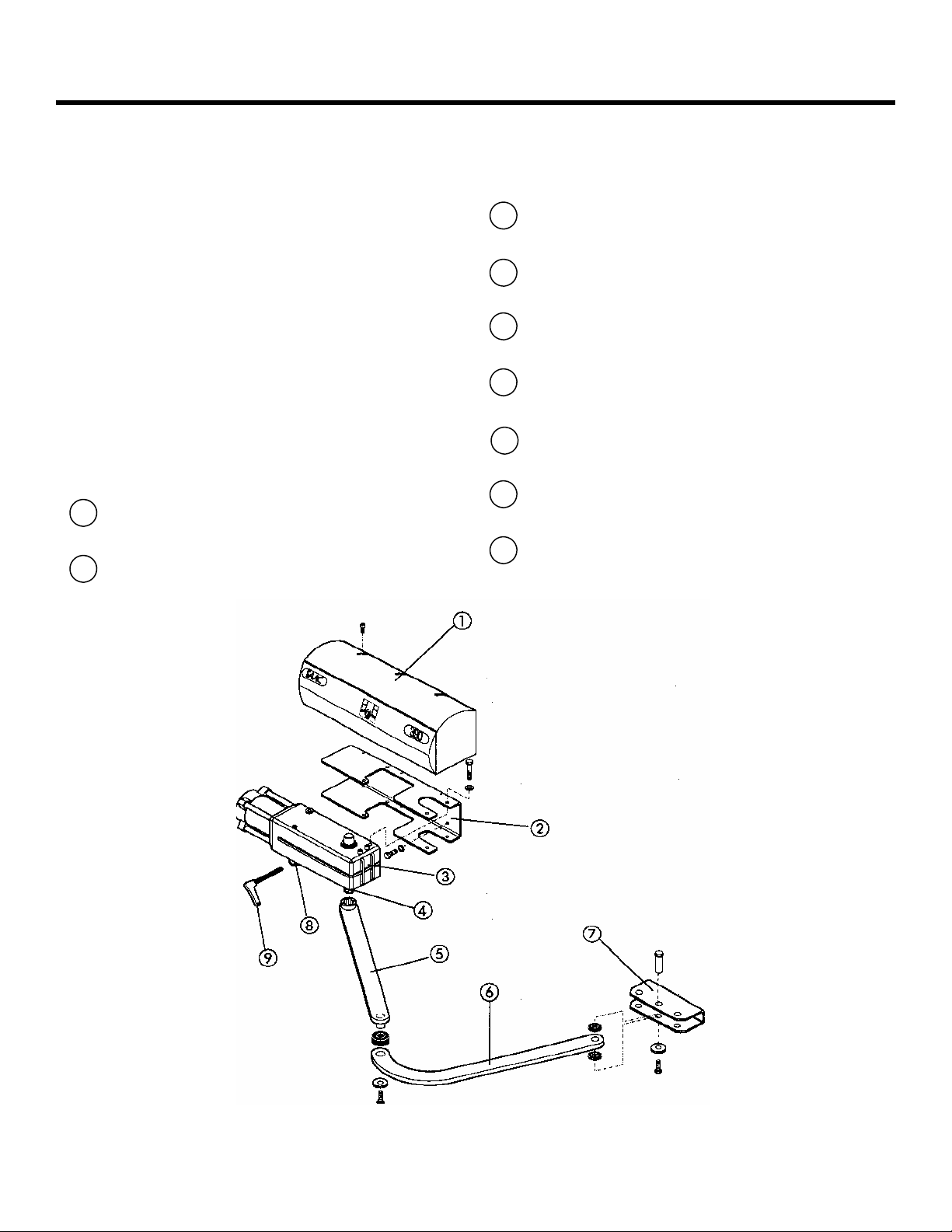
As you unpack the box, insure that all the parts listed
below are included (See Figure 2).
Control panel enclosure with control panel and
transformer.
The 390 Operator is supplied with the following parts
1
390 Operator Cover
2
Operator securing base-plate
390 Motor Assembly
3
Splined Shaft
4
5
Straight Arm (Articulated Arm)
Curved Lever (Articulated Arm)
6
Front Mounting Bracket
7
Manual Release
8
9
Manual Release Key
Figure 2. 390 Operator included parts.
Page 6

Page 6
July, 2006
390 24v Operator And
425 D Control Panel Installation Manual
THE 390 24V OPERATOR
GENERAL CHARACTERISTICS
The FAAC 390 24v Operator is an automatic gate
operator for a residential swinging gate leaf that is
ideal for large columns.
The self-contained 390 24v Operator consists of a
irreversible electromechanical motor and articulated
arm.
The locking the 390 24v Operator provides in the fully
opened and fully closed positions is a service device
rather than a security device. Additional, external locks
are recommended under the following conditions:
∗ It is a solid-faced gate.
∗ The length of the gate leaf is 6 ft (2 m) or longer.
∗ The installation requires tight security.
∗ The site is subject to vandalism.
∗ The site is subject to strong or very gusty wind
In two-operator gate installations, both (master/slave)
operators are wired to one control panel.
The electronic control panel is a microprocessor-based
controller that accepts a wide range of product
accessories and reversing devices, thus allowing for
flexible gate system design.
Also for the protection and proper operation of the 390
24v Operator, each operator has available optional limit
switches.
Built-in security and anti-crushing measures of the 390
24v Operator include built in reverse on contact and a
torque adjustment that controls the force transmitted to
the gate leaf through the 390 24v Operator.
The Manual Release mechanism is a key-operated device
that disengages (or engages) the gears in 390 24v
Operator. When the drive is disengaged, you can open
and close the gate leaf by hand. Such manual operation
of the gate is necessary during installation and useful
during prolonged power failures.
The torque of the 390 24v Operator is set during Basic
Programming of the 425 D Control Panel. (see page 19
for Basic Programming).
Reversing devices (such as inductive loops and
photocells) should be installed to provide non-contact
reversing operation.
WARNING: To insure that the installation meets the UL
325 Standards. A set of photo beam (Part Number
785163) must be installed anywhere that an entrapment
with the gate leaf(s) could happen.
The 425 D also has a built in battery back-up system
that can be used with the addition of 2 12V 7ah
batteries. The batteries must be wired in series to
provide 24VDC to the control panel during power
outages.
During prolonged power outages the manual release
may be used if needed.
INSTALLATION INSTRUCTIONS
Installing the 390 24v Operator involves preparing the
gate, installing the operator(s), installing the control
panel, programming control panel, and connecting
other operational controls.
Note: The following installation instructions assume
you are fully capable of installing an electromechanical
operator on a gate. This manual does not instruct you
in designing a gate, installing a gate (whether on
masonry, wood, or metal posts), or basic electrical
wiring. The installation tasks discussed in this manual
are tasks particular to the 390 24v Operator.
PREPARE THE GATE
Before you install the 390 24v Operator, you need to
prepare the gate itself for the operator. Be sure to do
the following:
Make sure that the gate structure is solidly built. Add
reinforcing crosspieces if necessary to the gate leaves.
Make sure that the gate moves smoothly on its hinges
without excessive friction by swinging it opened and
closed by hand. If necessary, lubricate all the gate's
moving parts.
Positive stops are needed with the 390 24v Operator
unless you have purchased the optional Limit Switch Kit
(FAAC Part Number 390682)
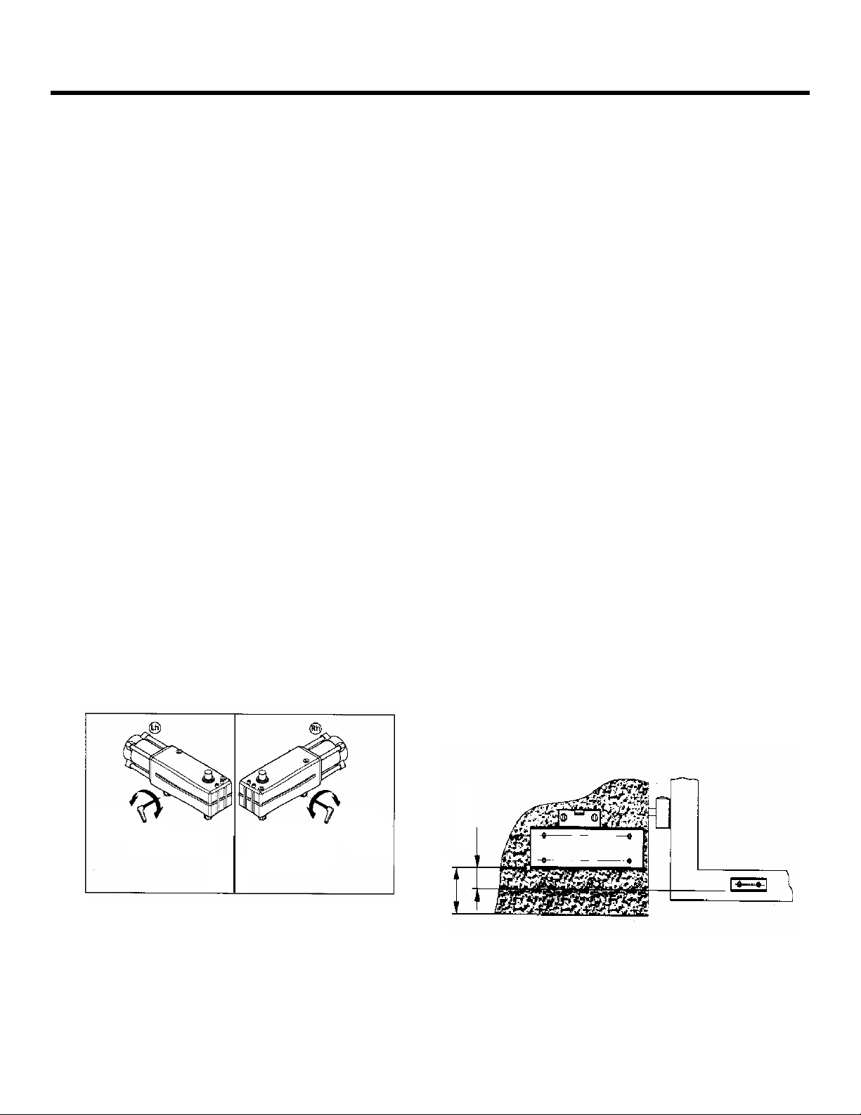
MANUAL RELEASE MECHANISM
To manual release the 390 24v Operator perform the
following steps as shown in figure 3.
Page 7
July, 2006
390 24v Operator And
425 D Control Panel Installation Manual
Page 7
If the gate has to be operated manually in the event of a
power outage, use the manual release mechanism as
follows:
Insert the supplied Allen wrench (manual release key)
and turn it by a half turn until it stops in the direction
shown in figure 3, depending on type of installation.
Now the 390 24v Operator is manual released. You can
move the gate freely.
RESTORING OPERATOR TO NORMAL OPERATION
To avoid an involuntary pulse from activating the gate
during the maneuver, before re-locking the operator
switch off power to the system.
Fit the supplied Allen wrench (manual release key) and
turn it by a half turn until it stops, in the direction
shown in figure 3, depending on type of installation.
INSTALLING THE OPERATOR
Once you have prepared the gate, you are ready to
proceed with the installation of the operator.
To ensure safety and an efficient automation, make sure
the following requirements are met:
∗ The gate structure must be suitable for automation.
In particular, make sure it is sufficiently sturdy and
rigid, and that its dimensions are in line with those
indicated in the technical specifications.
∗ Make sure that the leaves move properly without
any binding during their entire travel.
∗ Check if hinges are in good condition.
∗ Make sure the positive stops are in place. (unless
you are using the optional Limit Switch Kit)
MOUNTING DIMENSIONS
Install the operator by using the following tables. See
figures 5 & 6. The outward dimensions are ideal for an
“overhead” outward swinging garage/carriage door.
MOUNTING THE BASE PLATE
The 390 24v Operator Base Plate can be used for either
Right Hand (DX) or Left Hand (SX) installations.
Note: The splined shaft must always face down.
∗ Secure the base plate to the column and check to
see if it is level. Figure 4.
∗ Fit the 390 Operator into the base plate and secure
it with the 2 screws, nuts and lock washers. Figure 7
∗ Assemble the articulated arm and front mounting
bracket as shown in figure 8.
∗ Attach the articulated arm to the 390 Operator with
the supplied screw and washer. Figure 9.
∗ With the operator released, established the position
of the front mounting bracket to the gate by
checking dimensions C in figure 5 & 6. The bracket
can be welded or bolted to the gate leaf. See figure
10
∗ Attach the operator cover to the operator.
∗ Attach the power cord to the control panel.
LOCK
UNLOCK UNLOCK
Figure 3. Manual Release
LOCK
2 3/4 ”
7 3/4 ”
Figure 4. Operator Position
Page 8
Page 8
July, 2006
390 24v Operator And
425 D Control Panel Installation Manual
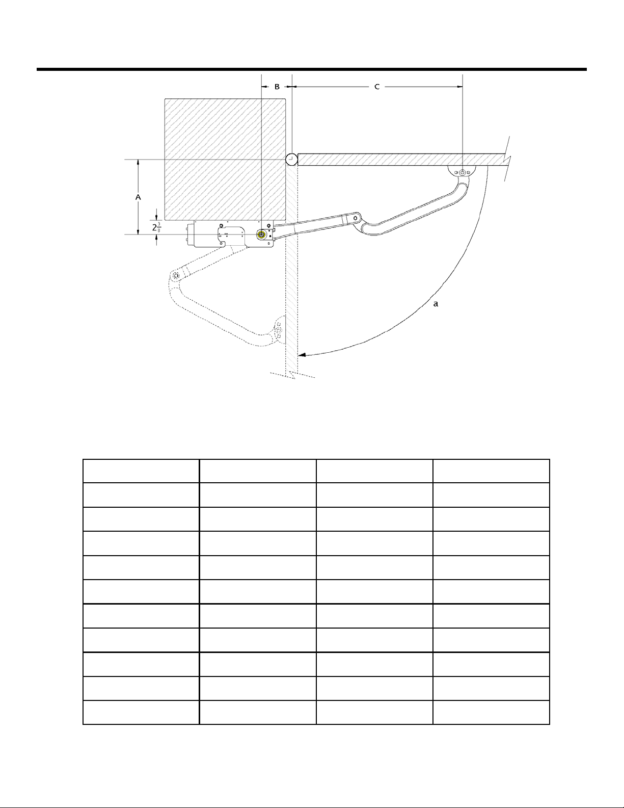
Figure 5. Dimensions for Inward Opening
Typical gate applications
A B C (max)
a°
2¼”- 4¼” 4¼”- 5¼” 28¾” 90°
4¼”- 6¼” 4¼”- 5¼” 28¼” 90°
6¼”- 8¼” 4¼”- 5¼” 28” 90°
8¼”- 10¼” 4¼”- 5¼” 27½” 90°
10¼”- 12¼” 4¼”- 5¼” 27” 90°
12¼”- 14¼” 4¼”- 5¼”
26¼” 90°
2¼”- 4¼” 7½”- 8¼” 25½” 120°
4¼”- 6¼” 9”- 10” 23½” 120°
6¼”- 8¼” 11½”- 12¼” 21¼” 120°
8¼”- 10¼” 12¼”- 13” 20” 120°
Page 9

July, 2006
390 24v Operator And
425 D Control Panel Installation Manual
Hinge
Page 9
Figure 6. Typical “overhead” outward swing mounting
dimensions for garage/carriage door applications.
A B C (max)
a°
2¼”- 4¼” 4¼”- 5¼” 28¾” 90°
4¼”- 6¼” 4¼”- 5¼” 28¼” 90°
6¼”- 8¼” 4¼”- 5¼” 28” 90°
8¼”- 10¼” 4¼”- 5¼” 27½” 90°
10¼”- 12¼” 4¼”- 5¼” 27” 90°
12¼”- 14¼” 4¼”- 5¼”
26¼” 90°
2¼”- 4¼” 7½”- 8¼” 25½” 120°
4¼”- 6¼” 9”- 10” 23½” 120°
6¼”- 8¼” 11½”- 12¼” 21¼” 120°
8¼”- 10¼” 12¼”- 13” 20” 120°
Page 10

Page 10
July, 2006
390 24v Operator And
425 D Control Panel Installation Manual
Figure 7
Figure 7 shows how to attach the operator
to the base plate.
Figure 9
Figure 9 shows how to attach the articulated
arm and operator cover to the operator.
390 Limit Switch Instructions
Figure 8
Figure 8 shows how to assemble the articulated
arm and front bracket.
Figure 10
Figure 10
Figure 10 shows how to attach the front mounting
bracket to the gate leaf(s).
When Using 1 Limit Switch (Open or Closed Stop)
When Using 2 Limit Switches (Open and Closed Stops)
Page 11

July, 2006
390 24v Operator And
425 D Control Panel Installation Manual
Page 11
Figure 1. The layout of a sample gate system
6
1
5
3
A
A
B
NOTE: Locate activation switches at
least10 ft from the gate.
7
6
2
8
7
1
A
4
5
C
3
B
A
C
D
9
8
1 Operator
2 Control Panel/Enclosure
3 Photocell A 2 × 18 AWG A 2 × 18 AWG
4 Power Switch B 4 × 14 AWG B 4 × 14 AWG
5 FAAC 5 Wire Cable for Master/Slave Connection and
Junction Box
6 Gate stops provided by built in limit switch
7 FAAC Key Activated Switch (T10) A 2 × 18 AWG A 2 × 18 AWG
8 Wiring to main circuit breaker D
110 VAC primary / 24 VAC 100 VA secondary
C 5 × 18 AWG C 5 × 18 AWG
2 × 12 AWG
Wire Gauges for Given Voltage
Page 12

July, 2006
Page 12
425 D Control Panel Installation Manual
390 24v Operator And
The 390 24v Operator
Page 13

July, 2006
390 24v Operator And
425 D Control Panel Installation Manual
390 24v Operator
POS PART NO. DESCRIPTION QTY
2 N/A Operator body 1
5 727292 Protective Cover 1
6 N/A Manual Release Assembly (Inner) 1
7 N/A Gear (Upper) 1
8 N/A Gear (Lower) 1
10 713001 Key (Manual Release Lever) 1
11 718189 Gear (Main Drive Shaft) 1
12 N/A Bushing Brass (Upper) 1
Page 13
Parts List
13 N/A Manual Release (Outer) 1
14 722471 Mounting Frame 1
15 N/A Bushing Brass (Bottom) 1
16 N/A Fender Washer 1
17 N/A Motor 24VDC 1
20 N/A Motor Housing 24VDC 1
21 N/A Snap Ring 1
22 N/A Seal (Lower) 1
23 6202 Bearing (Sealed) 4
24 6206 Bearing (Sealed) 2
25 N/A Nut (8mm x 1.25mm x 6.5mm) 1
26 N/A Spacer 1
27 N/A O-Ring (2.62mm x 61.60mm) 1
28 N/A Washer (8mm x 2mm) 1
29 N/A Snap Ring 1
30 N/A Snap Ring 1
31 N/A “C” Clip 1
32 N/A Screw Self Tapping (3.5mm x 9.5mm) 3
33 N/A Bolt (8mm x 110mm) 2
34 N/A Bolt (5mm x 16mm) 3
35 N/A Screw Cap (6mm x 70mm) 3
36 N/A Screw (4mm x 10mm) 3
Page 14

Page 14
July, 2006
390 24v Operator And
425 D Control Panel Installation Manual
THE 425 D CONTROL PANEL
GENERAL DESCRIPTION
The FAAC 425 D control panel is used to operate the
following models.
Swing gate operators:
415 412
390 770
The 425 D programming controls the following:
Operating logic: A, EP, logics available.
Pause time between opening and closing: Done
during the motor programming time.
Opening/Closing time: Self Learning. (During the
programming stage
Leaf delay on closing: adjustable from 1.5 to 10
seconds.
Leaf delay on opening: 1.5
The 425 D control panel should be installed in an
enclosure that is conveniently located as close as
possible to the gate operator. All electrical
connections from the control panel to the operator
must be made in a weatherproof junction box.
The 425 D control panel requires the 100VA
transformer (included) 115vac primary and 24vac
secondary. The power supply should be protected by
a 15 amp dedicated circuit breaker (not provided).
The installer is responsible for providing the main
power breaker switch, and for making sure that the
entire gate system meets all applicable electrical
codes. The installer should refer to the installation
manual for a given operator for more information.
N
OTE: An installation is U.L. compliant only
when you install the FAAC operators
according to the UL325 standards.
INSTALLING THE 425 D CONTROL
P
ANEL
Installing the control panel consists of the following
general steps:
∗ Connecting the main power to the control
panel
∗ Connecting the activating device
∗ Connecting the operator to the control panel
THE 425 D CONTROL PANEL INSTALLATION INSTRUCTIONS
∗ Checking the direction of the motor's rotation
∗ Connecting other devices to the control panel
∗ Set operating modes
CONNECT THE MAIN POWER SUPPLY
WARNING! Turn the main power off before you
make any electrical connections or before
programming.
The main power can be provided in a variety of
different ways.
1) Bring a 115VAC line into the enclosure and wire
to the terminals provided, and plug the
transformer into the outlet provided inside the
enclosure.
2) Plug the transformer into any 115VAC outlet and
bring the low voltage (24VAC) wires into the
enclosure wiring them directly to the control
panel as described below. Be sure to use the
appropriate size wire for longer runs.
CONNECT THE OPERATOR(S) TO THE
C
ONTROL PANEL
WARNING!
make any electrical connections.
USING A JUNCTION BOX
If an operator is more than 2 ft away from the control
panel, you must use a junction box for connection. Use
a U. L. Listed cord grip where the operator cord enters
the junction box.
Note: If you have a one-leaf gate design, the
operator must be connected to Motor 1 (terminals
APM1 and CHM1) in the CN2 Terminal Block
To wire up motor 1, connect the blue wire to terminal
APM1(on the CN2 terminal strip), the brown wire to
CHM1..
Note: If you want to delay the closing of one gate
leaf in a two-leaf gate design, be sure to connect
its operator to Motor 1.
In order to wire motor 2 in a bi-parting system, connect
the blue wire to terminal APM2 (on the CN2 terminal
strip), the brown wire to CHM2.
Turn the main power off before you
Page 15

July, 2006
390 24v Operator And
425 D Control Panel Installation Manual
Page 15
Figure 1. The 425 D Control Panel
FUSE RATINGS
F1 Main Power 10A
F2 Accessories/Charging Circuit
F3 Lamp .800mA
F4 Electric Lock 3.15A
F2
F1
RESET
F4
FCC1FCA1FCC2 FCA2
F3
-
+
P1 P2
FSW-C L FSW- OPSTOP
N.C.
COM
+
1.6A
RADIO
CN1 terminal block for main power
supply, battery connections and
accessory power
CN2 terminal block for connecting the
operator(s), lock, and lamp
CN3 limit switch connections
CN4 terminal block for low-voltage
accessories input
CN5 quick connector port for the
FAAC plug in radio receiver.
P1 Programming Push Button
P2 Programming Push Button
CONNECT OTHER DEVICES
WARNING! Turn the main power off before
you make any electrical connections.
POWER SUPPLY FOR ACCESSORIES: You can access a
24 VDC output for supplying power to
accessories through terminals +24V and –24V on
terminal block CN1. In most cases, this source
can be used to power 24 VDC accessories.
NOTE: The 425 D control panel allows a
maximum accessory load of 630mA.
R
EVERSING DEVICES: Reversing devices include
photocells, inductive loops, and so forth. All of
the reversing devices should have contacts of the
normally closed (N.C.) type. Where you connect a
device depends on whether you want the device
to operate during opening or during closing.
N
OTE: UL does not recognize the FAAC
system with loop detectors or safety edges.
FAAC photobeams must be used to comply
with UL 325.
To wire photobeams, refer to page 19 (see FSWOP
for opening photobeams, and FSWCL for closing
photobeams). Photobeams must be connected as
shown. See also page 19 for the wiring of
inductive loops. If using more than one reversing
device, they must be wired in series.
N
OTE: A shadow/intermittent loop cannot be
wired to for use when using the 425 D
control panel.
THE 425 D CONTROL PANEL INSTALLATION INSTRUCTIONS
Figure 2. The terminal strip wiring of the 425 D with
photobeams
Page 16

Page 16
July, 2006
390 24v Operator And
425 D Control Panel Installation Manual
ACTIVATING DEVICES AND RADIO RECEIVER: The
activating devices and radio receiver for your gate
must have normally open (N.O.) contacts. Connect
such devices to terminals OPEN A and COM.
N
OTE: The FAAC radio receiver plugs into
the 5 prongs labeled CN5 (Quick connect
port).
Page 19 shows how to connect a three or four wire
receiver.
FAAC PLUG IN RADIO RECIEVER: If you are
installing the FAAC Receiver use the quick-fit
connector CN5.
N
OTE: If your using both a receiver and
decoder, hard wire the decoder and plug in
the receiver.
OPEN/HOLD OPEN DEVICE: To open and hold open
the gate, simply maintain a contact across terminals
OPEN A and COM. (“A” Mode only)
STOP BUTTON: The stop button you install must
have normally closed (N.C.) contacts. Multiple stop
buttons must be wired in series. Connect your stop
device between terminals STOP and COM.
N
OTE: The 425 D will not operate the motors
without a closed circuit between STOP & COM.
The LED Indicators: The nine light emitting
diodes (LEDs) on the control panel can be used to
check for the proper function of the devices
attached to the panel. The LED lights are on
whenever the contacts are closed across each of the
respective terminals.
LED On Off
DL1 Power On Power Off
Closing
Safeties
Triggered
Opening
Safeties
Triggered
Stop Signal
Given
Limit Switches
Triggered
THE 425 D CONTROL PANEL INSTALLATION INSTRUCTIONS
DL7
FSW CL
DL8
FSW OP
DL3
STOP
DL2,DL3
DL4,DL5
Limits
Closing
Safeties Normal
Opening
Safeties Normal
Stop Device
Normal
Limit Switches
Normal
OP_A and OP_B (Partial Opening) should illuminate only
when an activating signal is sent for 2 and 1 gate leaves,
respectively. STOP should be illuminated except when
the stop button is pressed. FSWOP and FSWCL should be
illuminated except when the reversing devices, for
opening and closing, respectively, are triggered. Use the
LEDs and the next table to determine if the accessory
devices you have installed are operating properly.
Electric Locks: An electric lock can be wired to the
425 D in
provided). If a reversing stroke is needed to allow the
electric lock to release, this must be done in
programming.
See page 19 for the connections for a magnetic locking
device.
terminals ELS and ELS (24Vdc pulsed
WARNING LIGHT: Connect a warning light to
terminals labeled lamp in the CN2 terminal block.
The terminals provide an output voltage of 24 VDC,
maximum power 15 Watts. This output voltage will
power most 24 VDC warning lights.
N
OTE: The behavior of the warning light is as
follows. During programming the light will flash
every 1/2 second during opening and every 1 1/2
seconds during closing. If you are in automatic
mode (A), upon reaching the open position, the
output will remain on for 5 seconds to inform you
that the gate will close automatically. It will also
flash for up to 10 seconds if the gate is open and a
safety is triggered.
The output can also be set as a courtesy light that stays
illuminated for 90 seconds. See the programming
section (G0 and G1) for further details
SET OTHER OPERATING CONTROLS
WARNING
make any electrical connections.
You need to program the control panel for your gate's
operation. The 425 D Control Panel has on board
programming that controls a wide range of functions.
OPERATING LOGICS
NOTE: The 425 D Control Panel provides inputs
for opening reversing devices and closing
reversing devices. FAAC strongly recommends
the use of reversing devices, such as photocells
or other non-contact sensors.
•
A (automatic): The gate opens on command
and automatically closes after a pause phase. A
second command while opening is ignored; a
second command during the pause phase
interrupts the pause time; a second command
! Turn the main power off before you
Page 17

July, 2006
390 24v Operator And
425 D Control Panel Installation Manual
Page 17
during closing reopens the gate. A
maintained open command will hold the gate
open.
•
EP (semi-automatic, step by step): This
mode requires a command to open and a
command to close. A second command
during opening or closing causes the gate to
stop. A third command then reverses the
previous motion of the gate.
The two programming push buttons allow the
programming of the force, logic settings, etc
WARNING! Turn the main power off before you
make any electrical connections.
PAUSE TIME: The pause time between opening and
closing is set during the motor run time programming
section.
LEAF DELAY: You may choose to delay one leaf on
closing for overlapping gate leaves. Be sure the
operator on the leaf for delayed closing is connected
to Motor 1.
The opening leaf-delay time of 1.5 seconds cannot be
adjusted.
The closing leaf-delay time is adjustable from 1.5 to 10
seconds.
NOTE: If the opening/closing time is set at less than
the leaf delay time, the delayed leaf closes at the end
of the closing time.
SETTING THE DIP SWITCHES
Set the dip switches as follows:
OBSTACLE RECOGNITION
In the event that two obstacles are sensed in succession,
the motor(s) will stop. At this point the control panel will
require an activation signal which will cause the motor(s)
to run open and then close at slow speed to “reprogram”
the location of the open and closed limit switches.
THE 425 D CONTROL PANEL INSTALLATION INSTRUCTIONS
To the U. L. Listed gate operator
(a)
U.L. Listed
cord grip
Junction box
Legend
Blue
Brown
Black
Blue/Brown
To the U.L. Listed
control panel
(motors)
Conduit to U.L. Listed control panel enclosure according to N.E.C.
Figure 3.
Wiring detail (a) inside the junction box and (b) from the
junction box or operator to the high-voltage terminal strip
on the 425 D control panel
U.L. Listed Control Panel Enclosure
(b)
OP CL OP CL
Cord grip or conduit
from
U.L. Listed gate
operator(s)
425 D Control Panel
CN2
terminal strip
CN2
Op.1 Op.2
CN3/CN4
Ground
Page 18

Page 18
July, 2006
390 24v Operator And
425 D Control Panel Installation Manual
Activation Devices
(Free Exit Loop/ Phone/ Keypad)
COMOPEN
A
OPEN
C
NO
Partial Activation Device
(Open Motor 1
only on a dual gate)
COM
B
C
NO
Magnetic Lock
ELS -24V +24V
ELS
Limit Switch Jumpers
FCC2 FCA2FCA1CO MF FCC1 ENC2ENC1
-
Lock
+
24 vdc
Relay
N.C.
N.O.
COM
If limit s witc hes are not being us ed t han
they mus t be jumped out as s hown abov e
Reversing Photoc ells
3 & 4 Wire Radio Receivers
(DC Radios Only)
Additional
Reversing Devices
COM
CL
FSW
-24V+24V
NO = Normally Open, NC = Normally Closed, C = Common, TX = Transmitter, RX = Receiver
1
TX
2
COM
1
A
OPEN
If 4 Wire Receive r
NO
2
3
RX
-24V+24V
4
5
C
-
+
THE 425 D CONTROL PANEL INSTALLATION INSTRUCTIONS
Figure 4. Common Accessories wired to 425 D Control Panel
Page 19

July, 2006
390 24v Operator And
425 D Control Panel Installation Manual
PROGRAMMING
WARNING! Turn off the main power before you
make any electrical connections or set any
switches inside the control panel box.
To program the automated system, the
“Programming Mode” must be accessed.
The 425D has two push buttons labeled P1 and P2
that are used to program how the control panel
operates and responds to inputs.
1. The display should show “— —”.
2. Press and hold the P2 button for 5 seconds
until the display shows the first parameter.
3. To change the parameter values use the P1
button.
4. Use the P2 button to move from parameter to
parameter.
5. If no buttons are pushed for 60 seconds then
the board will automatically exit
programming.
6. Continuing all the way through the program to
the last parameter will also exit the program.
Use the following table to program the
parameters required for your installation.
Page 19
DISPLAY
LEAF DELAY
LOGIC SETTING
E P
A
ACTIVITATI ON COMMAND
Open/Close/Open
Open/Stop/Close/Stop
SECURITY MODE
Only useful in EP Logic
Only useful in A Log i c
REVERSING STROKE (useful with electric locks)
DESCRIPTION
1.5 seconds
3 seconds
6 seconds
10 seconds
THE 425 D CONTROL PANEL INSTALLATION INSTRUCTIONS
PROGRAM BUTTONS
Left Right
P1 P2
DISPLAY DESCRIPTION
FORCE SETTING (Force Applied to the Gate)
Mini mu m fo r ce , maxi mum
sensitivity
Medium low force, maximum
sensitivity
Medium high force, minimum
sensitivity
Maximum force, minimum
sensitivity
Disabled
Enabled
COURTESY LIGHT/WARNING LIGHT
Flashing Light
Courtesy Light (Light stays lit solid for
90 seconds)
DECELERATION PERCENTAGE SETTING
20% of opening run time
10% of opening run time
DECELERATION SPEED (SLOW DOWN SPEED)
High
Low
LIMIT SWITCHES (WITH/WITHOUT)
Not using limit swit ches
Using limit switches
NUMBER OF MOTORS
One operator connected
Two operators connected
Page 20

Page 20
July, 2006
390 24v Operator And
425 D Control Panel Installation Manual
DISPLAY DESCRIPTIONS
The following table shows the descriptions of the display
during a normal operating procedure
Value Shows Descriptions
—— ——
Gate Closed and at Rest
OP Gate is Opening (Open in “E” Mode)
tc Timer to Close (Pause Time)
CL Gate is Closing
P
ROGRAMMING THE MOTOR RUN TIME
NOTE: The operators will run at slow speed during the motor
run time programming phase.
The 425D features a self learning function for programming
the motor run time, pause time, and deceleration of the 390
24V Operator(s). Follow the procedure below to complete this
function.
1. Manually release the 390 operator(s), move the gate(s) to
the halfway position, and reengage the operator(s). See
figure 3, page 5.
2. Turn the power on. Ensure that the power led (DL1) is on.
3. Press and hold the P2 button until the display shows its
first value. (Example A1,A2,A3, Or A4)
4. Give the panel an open activation with any normally open
device wired to the OPEN A and COM terminals or the
FAAC plug in radio receiver. Motor 2 should close first,
followed by motor 1.
5. If either gate moves toward the open direction, touch the
two RESET (JMP1) pins, (see figure 2) with a small
screwdriver or piece of wire. This will cause the gate to
stop.
6. Turn the power off to the control panel and reverse the
motor wires to the operator that ran open. Turn the
power back on to the control panel and start again at
step 1.
7. Once the motor(s) is (are) running toward the closed
position, it (they) should do so until the closed limit
switch is reached.
8. After 2 seconds, motor 1 should begin to run open, after
and after another 2 seconds motor 2 should run open. It
(they) continue until the open limit switch(s) is (are)
reached.
9. When the gate(s) reach the open position, the control
panel begins to count the pause time. Once the desired
pause time (timer to close) has elapsed, give the panel an
open activation. Motor 2 should begin to close, followed
by motor 1. The gate(s) will run until the closed limit
switch(s) is (are) reached.
10. Programming is now complete. The display will show
“— —”.
THE 425 D CONTROL PANEL INSTALLATION INSTRUCTIONS
FUSE RATINGS
F1 = 10Amp
F2 = 1.6Amp
F3 = .800mAmp
F4 = 3.15Amp
Fuse Protects
Main Power
250V
Accessories/Charging
250V
250V
250V
Circuit
Flashing Light
Electric Lock Output
Page 21

July, 2006
390 24v Operator And
425 D Control Panel Installation Manual
MAINTENANCE
Page 21
THE 390 24VOPERATOR
The FAAC 390 24V Operator requires no maintenance.
Periodically inspect the operator, however, to ensure
continued proper operation.
SAFETY IN GATE DESIGN
• A gate is a potential traffic hazard, so it is
important that you locate the gate far enough
away from the road to eliminate the potential
of traffic getting backed up. This distance is
affected by the size of the gate, how often it is
used, and how fast the gate operates.
• The operator you choose to install on your
gate must be designed for the type and size of
your gate and for the frequency with which you
use the operator.
• Your gate must be properly installed and must
work freely in both directions before the
automatic operator is installed.
• An automatic operator should be installed on
the inside of the property/fence line. Do not
install the operator on the public side of the
property/fence line.
• Outward swinging gates with automatic
operators should not open into a public area.
THE 425 D CONTROL PANEL
Keep the Control Panel free from spider webs, insects,
etc. Otherwise the Control Panel requires no
maintenance.
• Pedestrians should not use a vehicular gate
system. Prevent such inappropriate use by
installing separate gates for pedestrians.
• The operating controls for an automatic gate
must be secured to prevent the unauthorized
use of those controls.
• The controls for an automatic gate should be
located far enough from the gate so that a
user cannot accidentally touch the gate when
operating the controls.
• Exposed, reachable pinch points on a gate are
potentially hazardous and must be eliminated
or guarded.
• It is extremely unsafe to compensate for a
damaged gate by over tightening a clutch or
increasing hydraulic pressure.
• An automatic gate operator should not be
installed on a gate if people can reach or
extend their arms or legs through the gate.
Such gates should be guarded or screened to
Page 22

Page 22
425 D Control Panel Installation Manual
390 24v Operator And
TROUBLESHOOTING
WARNING! Before you do any work on the control panel,
be sure to turn off the main power.
NOTE: Any control panel specific information in the following applies to the 455 D control panel only.
July, 2006
PROBLEM: THE GATE DOES NOT RESPOND TO
AN ACTIVATING SIGNAL.
SOLUTION:
You should have at least one operator wired to
terminals APM1 and CHM1.
Verify that the LEDs FSWOP, FSWCL, and the STOP are
illuminated. If they are not illuminated, be sure that you
have closed circuits in the stop and reversing inputs.
Verify that your activating device works properly. OPEN
A should illuminate when you signal the gate to open. If
OPEN A does not illuminate when you signal the gate,
then the problem may be in your activating device. Short
across terminals OPEN A and COM. If the short causes
the gate to open, then the problem is in the activating
device. Repair or replace the device
.
PROBLEM: THE GATE DOESN'T OPEN (OR CLOSE)
THOUGH THE MOTORS ARE RUNNING.
SOLUTION:
Make sure that the motor is running in the right
direction, and make sure the Manual Release
mechanism has fully engaged the system.
PROBLEM: THE GATE OPENS BUT DOES NOT
CLOSE.
SOLUTION:
Make sure you have selected the desired operating
mode.
Verify that the reversing devices are working properly.
FSWOP and FSWCL should be illuminated except when a
reversing device is triggered. If either does not
illuminate, then one of your reversing devices is
preventing the gate from responding to your signal.
Check your reversing devices.
If no reversing devices are installed, make sure a circuit
is installed between appropriate terminals.
PROBLEM: THE GATE DOES NOT FULLY OPEN
(OR CLOSE).
SOLUTION:
Check the operator's open/close time selection. You
should set a time that is just longer than the rated
speed of your model of operator. For example, because
the 415 CBAC has a rated opening time of 13 sec, you
should set the time at 20 or 25 seconds.
Check to see that there are no obstructions in the path
of the gate or that the hinges are not binding.
PROBLEM: THE OPERATOR DOESN'T WORK
SMOOTHLY AND THE GATE JERKS AS IT OPENS
AND CLOSES.
SOLUTION:
Make sure the Manual Release Mechanism has fully
engaged the worm screw operation of the operator.
Make sure that a flexible gate leaf is not the problem. If
the gate leaf flexes, then stiffen the gate or use a slower
operator.
Page 23

July, 2006
390 24v Operator And
425 D Control Panel Installation Manual
Page 23
NOTES
Page 24

July, 2006
390 24v Operator And
425 D Control Panel Installation Manual
LIMITED WARRANTY
Page 24
To the original purchaser only: FAAC International,
Inc., warrants, for twenty-four (24) months from the
date of invoice, the gate operator systems and other
related systems and equipment manufactured by FAAC
S.p.A. and distributed by FAAC International, Inc., to be
free from defects in material and workmanship under
normal use and service for which it was intended
provided it has been properly installed and operated.
FAAC International, Inc.'s obligations under this
warranty shall be limited to the repair or exchange of
any part of parts manufactured by FAAC S.p.A. and
distributed by FAAC International, Inc. Defective
products must be returned to FAAC International, Inc.,
freight prepaid by purchaser, within the warranty
period. Items returned will be repaired or replaced, at
FAAC International, Inc.'s option, upon an examination
of the product by FAAC International, Inc., which
discloses, to the satisfaction of FAAC International, Inc.,
that the item is defective. FAAC International, Inc. will
return the warranted item freight prepaid. The products
manufactured by FAAC S.p.A. and distributed by FAAC
International, Inc., are not warranted to meet the
specific requirements, if any, of safety codes of any
particular state, municipality, or other jurisdiction, and
neither FAAC S.p.A. or FAAC International, Inc., assume
any risk or liability whatsoever resulting from the use
thereof, whether used singly or in combination with
other machines or apparatus.
Any products and parts not manufactured by FAAC
S.p.A. and distributed by FAAC International, Inc., will
carry only the warranty, if any, of the manufacturer. This
warranty shall not apply to any products or parts thereof
which have been repaired or altered, without FAAC
International, Inc.'s written consent, outside of FAAC
International, Inc.'s workshop, or altered in any way so
as, in the judgment of FAAC International, Inc., to affect
adversely the stability or reliability of the product(s) or
has been subject to misuse, negligence, or accident, or
has not been operated in accordance with FAAC
International, Inc.'s or FAAC S.p.A.'s instructions or has
been operated under conditions more severe than, or
otherwise exceeding, those set forth in the
specifications for such product(s). Neither FAAC S.p.A.
or FAAC International, Inc., shall be liable for any loss or
damage whatsoever resulting, directly or indirectly,
from the use or loss of use of the product(s). Without
limiting the foregoing, this exclusion from liability
embraces a purchaser's expenses for downtime or for
making up downtime, damages for which the purchaser
may be liable to other persons, damages to property,
and injury to or death of any persons. Neither FAAC
S.p.A. or FAAC International, Inc., assumes nor
authorizes any person to assume for them any other
liability in connection with the sale or use of the
products of FAAC S.p.A. or FAAC International, Inc. The
warranty hereinabove set forth shall not be deemed to
cover maintenance parts, including, but not limited to,
hydraulic oil, filters, or the like. No agreement to replace
or repair shall constitute an admission by FAAC S.p.A. or
FAAC International, Inc., of any legal responsibility to
effect such replacement, to make such repair, or
otherwise. This limited warranty extends only to
wholesale customers who buy directly through FAAC
International, Inc.'s normal distribution channels. FAAC
International, Inc., does not warrant its products to end
consumers. Consumers must inquire from their selling
dealer as to the nature and extent of that dealer's
warranty, if any.
This warranty is expressly in lieu of all other
warranties expressed or implied including the warranties of merchantability and fitness for use. This
warranty shall not apply to products or any part
thereof which have been subject to accident, negligence, alteration, abuse, or misuse or if damage was
due to improper installation or use of improper
power source, or if damage was caused by fire, flood,
lightning, electrical power surge, explosion, wind
storm, hail, aircraft or vehicles, vandalism, riot or
civil commotion, or acts of God.
FAAC International, Inc.
303 Lexington Avenue
Cheyenne, WY 82007
www.faacusa.com
 Loading...