

Page 1

415 L LS 24V
Swing Gate Operator
UL325 - UL991
FAAC International Inc.
Headquarter & East Coast Operations
5151 Sunbeam Road
Suites 9-11
Jacksonville, FL 32257
Tel. 866 925 3222
www.faacusa.com
FAAC International Inc.
West Coast Operations
357 South Acacia Avenue
Unit 357
Fullerton, CA 92831
Tel. 800 221 8278
Page 2

CONTENTS
IMPORTANT SAFETY INFORMATION 3
1. DESCRIPTION 6
2. DIMENSIONS 6
3. TECHNICAL SPECIFICATIONS 7
4. INSTALLATION 7
Important Safety Instructions 3
Important Installation Instructions 3
General Safety Precautions 4
UL325 Gate Operator Classications 5
Installing the Warning Signs 5
4.1 Electrical Set-up (Standard System) 7
4.2 Preliminary Checks 7
4.3 Installation Dimensions 8
4.4 Installing the Operator 9
4.5 Wiring the Operator 10
4.6 Adjusting the Limit Switches 11
4.7. Start-up 12
5. MANUAL OPERATION 12
6. MAINTENANCE 13
7. REPAIRS 13
8. 415 L LS PARTS DIAGRAM 14
E024U CONTROL BOARD AND LIMITED WARRANTY A2 - A18
Read this instruction manual before you begin installing the product.
= Information regarding personal safety and proper maintanence of the product.
FAAC Model 415 L LS 24V - Rev: 02 - JUN 2012
2
FAAC Model 415 L LS 24V Swing Gate Operator
Page 3

IMPORTANT SAFETY INFORMATION
Important Safety Instructions
WARNING: TO REDUCE THE RISK OF SEVERE
INJURY OR DEATH:
• READ AND FOLLOW ALL INSTRUCTIONS.
• Never let children operate or play with the gate
controls. Keep remote controls away from children.
• Always keep people and objects away from the
gate. NO ONE SHOULD CROSS THE PATH OF A
MOVING GATE.
• Test the gate operator monthly. The gate MUST
reverse on contact with a rigid object or when an
object activates a non-contact sensor. If necessary,
adjust the force or the limit of travel and then retest
the gate operator. Failure to properly adjust and retest
the gate operator can increase the risk of injury or
death.
• Use the manual release mechanism only when the
gate is not moving.
• KEEP GATE PROPERLY MAINTAINED. Have
a qualied service person make repairs to gate
hardware.
• The entrance is for vehicles only. Pedestrians must
use a separate entrance.
• SAVE THESE INSTRUCTIONS.
Important Installation Instructions
1. Install the gate operator only when the following conditions have been met:
• The operator is appropriate for the type and usage
class of the gate.
• All openings of a horizontal slide gate have been
guarded or screened from the bottom of the gate to
a minimum of 4 feet (1.25 m) above the ground to
prevent a 2.25 inch (55 mm) diameter sphere from
passing through openings anywhere in the gate or
through that portion of the adjacent fence that the
gate covers when in the open position.
• All exposed pinch points are eliminated or guarded.
• Guarding is supplied for exposed rollers.
2. The operator is intended for installation on gates used
by vehicles only. Pedestrians must be provided with a
separate access opening.
3. To reduce the risk of entrapment when opening and
closing, the gate must be installed in a location that
allows adequate clearance between the gate and
adjacent structures. Swinging gates shall not open
outward into public access areas.
4. Before installing the gate operator, ensure that the gate
has been properly installed and that it swings freely in
both directions. Do not over-tighten the operator clutch
or pressure relief valve to compensate for a damaged
gate.
5. User controls must be installed at least 6 feet away
from any moving part of the gate and located where the
user is prevented from reaching over, under, around
or through the gate to operate the controls. Controls
located outdoors or those that are easily accessible
shall have security features to prevent unauthorized
use.
6. The Stop and/or Reset buttons must be located within
line-of-sight of the gate. Activation of the reset control
shall not cause the operator to start.
7. All warning signs and placards must be installed
and easily seen within visible proximity of the gate. A
minimum of one warning sign shall be installed on each
side of the gate.
8. For gate operators that utilize a non-contact sensor
(photo beam or the like):
• See instructions on the placement of non-contact
sensors for each type of application.
• Exercise care to reduce the risk of nuisance tripping,
such as when a vehicle trips the sensor while the
gate is still moving.
• Locate one or more non-contact sensors where the
risk of entrapment or obstruction exists, such as at
the reachable perimeter of a moving gate or barrier.
• Use only FAAC “Photobeam” photoelectric eyes to
comply with UL325.
FAAC Model 415 L LS 24V Swing Gate Operator
3
Page 4

Important Installation Instructions (continued)
General Safety Precautions
9. For gate operators that utilize a contact sensor (edge
sensor or similar):
• Locate one or more contact sensors where the risk
of entrapment or obstruction exists, such as at the
leading edge, trailing edge, and post mounted both
inside and outside of a vehicular horizontal slide
gate
• Locate one or more contact sensors at the bottom
edge of a vehicular vertical lift gate.
• Locate one or more contact sensors at the bottom
edge of a vertical barrier (arm).
• Locate one or more contact sensors at the pinch
point of a vehicular vertical pivot gate.
• Locate hard-wired contact sensors and wiring so
that communication between sensor and gate
operator is not subjected to mechanical damage.
• Locate wireless contact sensors, such as those
that transmit radio frequency (RF) signals, where
the transmission of signals are not obstructed or
impeded by building structures, natural landscaping
or similar hindrances. Wireless contact sensors shall
function under their intended end-use conditions.
• Use only FAAC MSE MO, CN60 or M60 edge
sensors.
Gate Construction
Vehicular gates should be constructed and installed
in accordance with ASTM F2200: Standard Specication for Automated Vehicular Gate Construction.
For more information, contact ASTM at: www.astm.org
Installation
• If you have any questions or concerns regarding the
safety of the gate operating system, do not install the
operator and consult the manufacturer.
• The condition of the gate structure itself directly
affects the reliability and safety of the gate operator.
• Only qualied personnel should install this equipment.
Failure to meet this requirement could cause severe
injury and/or death, for which the manufacturer
cannot be held responsible.
• The installer must provide a main power switch that
meets all applicable safety regulations.
• It is extremely unsafe to compensate for a damaged
gate by increasing hydraulic pressure.
• Install devices such as reversing edges and photo
beams to provide better protection for personal
property and pedestrians. Install reversing devices
that are appropriate to the gate design and
application.
• Before applying electrical power, ensure that voltage
requirements of the equipment correspond to the
supply voltage. Refer to the label on your gate
operator system.
Usage
• Use this equipment only in the capacity for which it
was designed. Any use other than that stated should
be considered improper and therefore dangerous.
• The manufacturer cannot be held responsible
for damage caused by improper, erroneous or
unreasonable use.
• If a gate system component malfunctions, disconnect
the main power before attempting to repair it.
• Do not impede the movement of the gate, you may
injure yourself or damage the gate system as a result.
• This equipment may reach high thermal temperatures
during normal operation, therefore use caution when
touching the external housing of the gate operator.
• Use the manual release mechanism according to the
procedures presented in this manual.
• Before performing any cleaning or maintenance
operations, disconnect power to the equipment.
• All cleaning, maintenance or repair work must
performed by qualied personnel.
4
FAAC Model 415 L LS 24V Swing Gate Operator
Page 5
UL325 Gate Operator Classications
RESIDENTIAL VEHICULAR GATE OPERATOR CLASS I
A vehicular gate operator system intended for use in a single family dwelling, garage or associated parking area.
COMMERCIAL / GENERAL ACCESS VEHICULAR GATE OPERATOR CLASS II
A vehicular gate operator system intended for use in commercial locations or buildings such as multi-family housing
units (ve or more single family units), hotels, parking garages, retail stores or other buildings that service the general
public.
INDUSTRIAL / LIMITED ACCESS VEHICULAR GATE OPERATOR CLASS III
A vehicular gate operator system intended for use in industrial locations or buildings such as factories, loading docks
or other locations not intended to service the general public.
RESTRICTED ACCESS VEHICULAR GATE OPERATOR CLASS IV
A vehicular gate operator system intended for use in guarded industrial locations or buildings such as airport security
areas or other restricted access locations that do not service the general public, and in which unauthorized access is
prevented via supervision by security personnel.
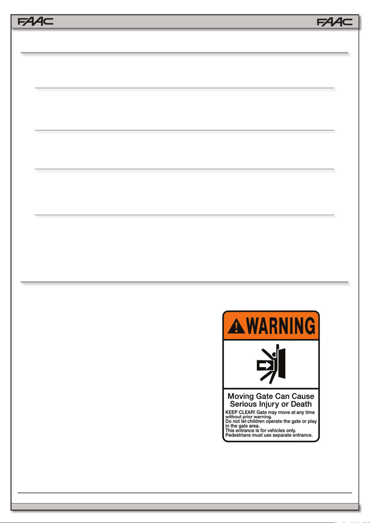
Installing the Warning Signs
This FAAC swing gate operator is supplied
with two warning signs to alert people that a
possible hazard exists and that appropriate
actions should be taken to avoid the hazard or
to reduce exposure to it.
Permanently install one warning sign on each
side of the gate so they are fully visible to
trafc and pedestrians.
Use appropriate hardware such as metal
screws (not supplied) to permanently install
each warning sign.
FAAC Model 415 L LS 24V Swing Gate Operator
5
Page 6
Model 415 L LS 24V Swing Gate Operator
5¾
4¼
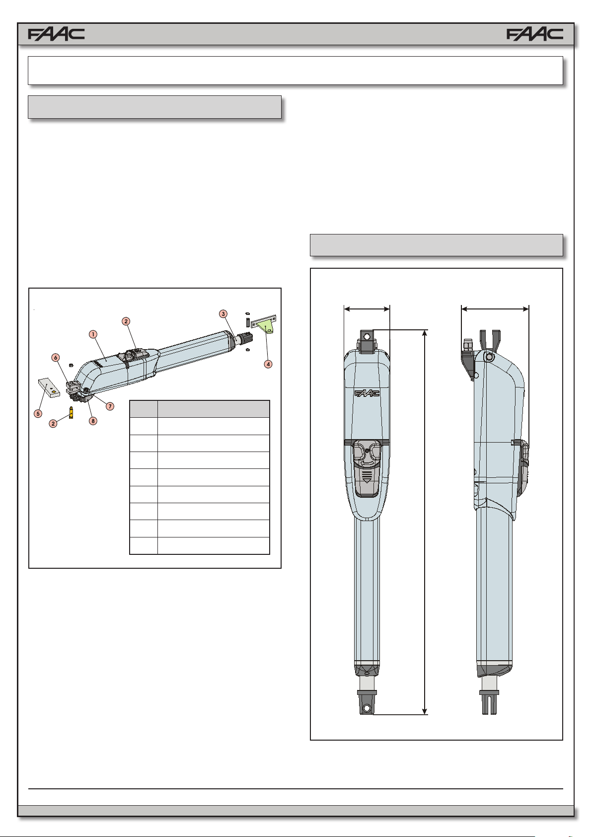
1. DESCRIPTION
The FAAC 415 is an automatic gate operator for swinging
gate leafs. The 415 Operator is useful in residential applications and can accommodate gate leafs up to 14 ft long. The
self-contained 415 Operator consists of an electric motor
that drives a worm screw housed in an aluminum casing.
The locking provided by the 415 Operator (in the fully
opened and fully closed positions) is a service device rather
than a security device.
Also, for the protection and proper operation of the 415 Operator, each operator has built in limit switches, so positive
stops are not needed.
Fig. 1
The 415 Operator automated system was designed and built
for controlling vehicle access. Avoid any other use what so
ever.
NOTES:
• Use suitable conduit to lay electric cables.
• To avoid any kind of interference, always use individual
sheaths to separate low-voltage accessories and control
cables from 115V~ power supply cables.
2. DIMENSIONS
Pos. Description
Built-in security and anti-crushing measures of the 415
Operator include built in reverse on contact and a torque
adjustment that controls the force transmitted to the gate leaf
through the 415 Operator.
The Manual Release mechanism is a key accessed device
that disengages (or engages) the cylinder on the 415 Operator. When the drive is disengaged, you can manually open
and close the gate leaf by hand.
Such manual operation of the gate is necessary during
installation and useful during prolonged power failures. The
torque of the 415 Operator is set using the Control Panel.
Reversing devices (such as inductive loops and photocells)
should be installed to provide non-contact reversing operation.
1 Operator
2 Release Device
3 Rod
4 Front Bracket
5 Rear Bracket
6 Rear Fitting
7 Rear Fitting Pin
8 Terminal Board Cover
* Measurements in Inches
37
Fig. 2
6
FAAC Model 415 L LS 24V Swing Gate Operator
Page 7
3. TECHNICAL SPECIFICATIONS
SPECIFICATION 415 L LS 24V
Power Supply 24 VDC
Power (W) 70
Current (A) 3
Thrust (lbf) 630
Effective Stroke (inches) 15
Rod Extension Speed (inches/sec) 0.5
Max Leaf Length (feet) 15
Cycle per hour at 68˚F (approx) 75
4.2 Preliminary Checks
The condition of the gate structure directly affects the reliability and safety of the automated system. Before installing the
415 Operator, prepare the gate for the operator by performing
the following:
• Make sure that the gate structure is solidly built. Add rein-
forcing crosspieces to the gate leaves if necessary.
• Make sure that the gate moves smoothly on its hinges
without excessive friction by swinging it opened and
closed by hand. If necessary, lubricate all the gate’s
moving parts.
Positive stops are not needed with the 415 operator, the built
limit switches can be used to limit the rod travel
Class or Operation Residential
Ambient Operating Temperature
-4 to +131
Range (˚F)
Operator Weight (lbs) 17.5
Protection Class IP 54
4. INSTALLATION
4.1 Electrical Set-up (Standard System)
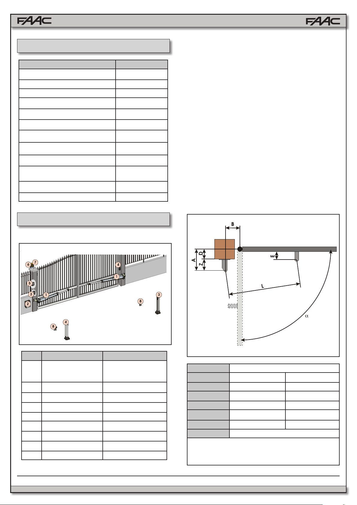
4.3 Installation Dimensions
Determine the mounting position of the operator with
reference to Fig. 4.
Ensure that the distance between the open leaf and any
obstacles (walls, fences etc.) is greater than the dimensions
of the operator.
Pos. Description Cables
1 Operators 2 x AWG 14 (max 30’)
AWG 12 (max 50’)
AWG 10 (max 100’)
1 Limit Switches 3 x AWG 20
2 Control Unit 3 x AWG 14 (AC power)
3 TX Photocells 4 x AWG 20
4 RX Photocells 2 x AWG 20
5 Key-operated Switch 2 x AWG 20
6 Flashing Lamp 2 x AWG 14
7 Receiver 3 x AWG 20
8 Mechanical Stops -
FAAC Model 415 L LS 24V Swing Gate Operator
Fig. 3
Fig. 4
MODEL 415 L LS 24V
90° 110°
A 7⅝ 6⅝
B 7⅝ 6⅝
(1)
D
(2)
Z
L 50¾ 50¾
(2)
E
5 4⅜
2¾ 2¾
1¾
(1)
max. dimension
(2)
min. dimension
* Dimensions
in Inches
7
Page 8
Guidelines for Determining Installation Dimensions
• For 90° leaf openings: A+B=L
• For leaf openings exceeding 90°: A+B<L
• Smaller A and B dimensions provide higher periph-
eral leaf speed.
• Limit the difference between A and B dimensions to
less than 1.5 inches. Greater differences may cause
speed variations during gate opening and closing
movements.
• Maintain a Z dimension that ensures that the operator
does not strike the pillar.
• In LS models, limit switches are triggered during the
rst and last 1.25 inches of gate travel. Therefore
select A and B dimensions that utilize the entire operator travel. Short travel ranges can restrict or cancel the
limit switch adjustment range.
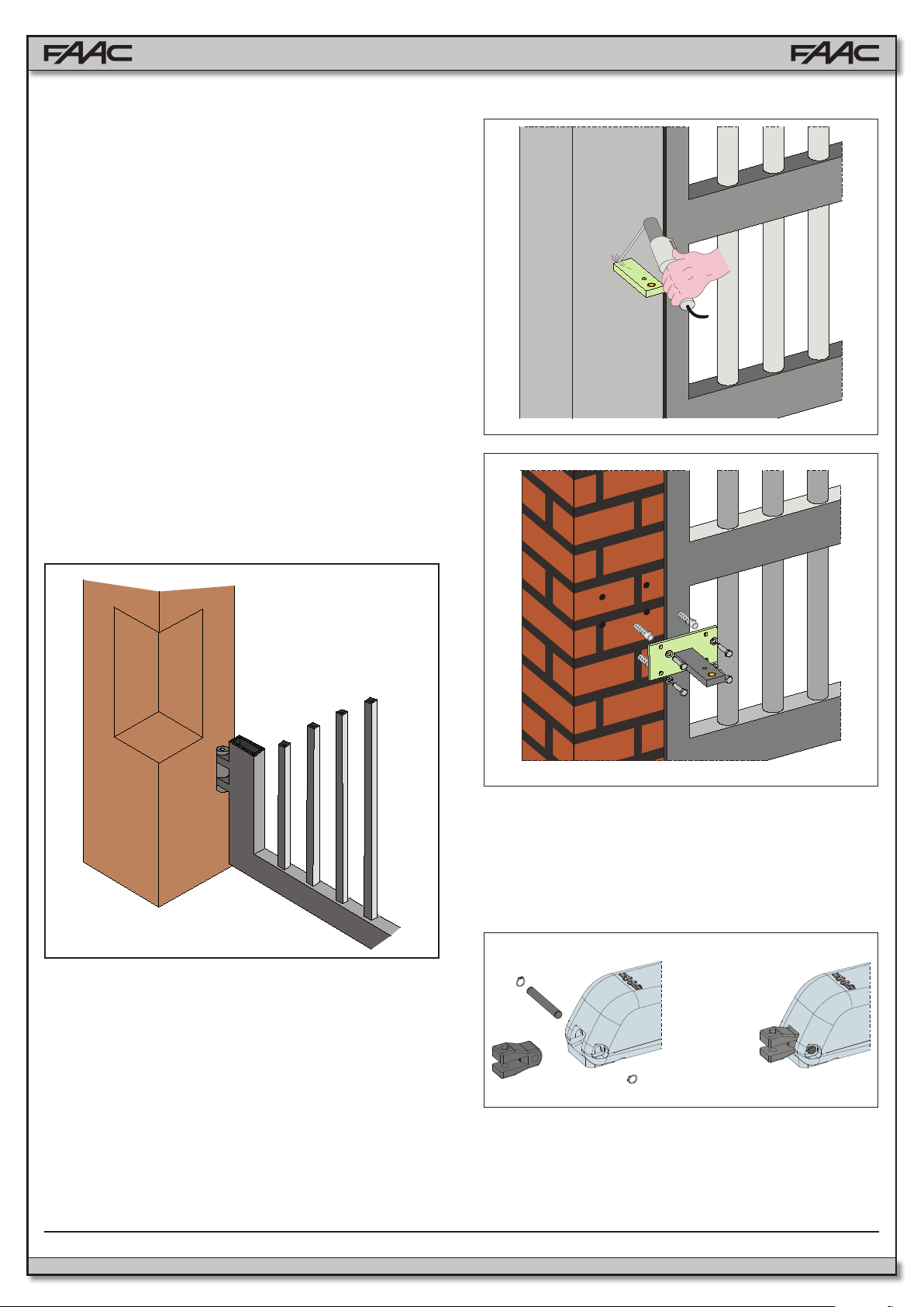
If pillar dimensions or hinge position do not allow installation of the operator, cut a niche into the pillar (as shown in
Fig. 5) in order to maintain the A dimension as determined.
The dimensions of the niche should enable easy installation, rotation and operation of the release device.
Fig. 6
Fig. 5
4.4. Installing the Operator
1. Fix the rear bracket in the position you previously determined in Section 4.3.1.
• For iron pillars, carefully weld the bracket directly onto
the pillar (Fig. 6).
• For masonry pillars, use a suitable plate (optional) for
which to attach the unit (Fig. 7). Make use of a suitable
fastening system. Then carefully weld the bracket to the
plate.
While fastening the bracket, use a level to ensure that it
is perfectly horizontal.
Fig. 7
2. Assemble and attach the rear tting to the operator (Fig.
8).
3. Set the 415 Operator to manual operation (see Section 6).
4. Completely extend the rod until it reaches the limit stop
(Fig. 9, Ref. 1).
Fig. 8
5. Re-lock the operator (see Section 6.1).
8
FAAC Model 415 L LS 24V Swing Gate Operator
Page 9
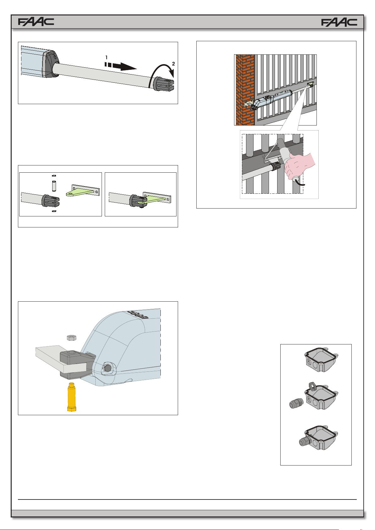
Fig. 9
6. Turn the rod one half revolution clockwise (Fig. 9, Ref. 2).
7. Assemble the front bracket as shown in Fig. 10.
8. Fix the operator to the rear bracket by means of the supplied pins as shown in Fig. 11.
Fig. 12
Fig. 10
Attention: allow the bracket to cool before fastening the
operator to it.
9. Close the leaf and, while keeping the operator perfectly
horizontal, determine the fastening point of the front
bracket (Fig.12).
10. Temporarily x the front bracket with two welding spots
(Fig.12).
Fig. 11
Note: if the gate structure does not allow a xed bracket
fastening it is necessary to create a sturdy supporting
base in the gate structure.
11. Release the operator (see Section 6) and manually check
that the gate moves regularly without friction or hindrances. Ensure that it opens completely and stops at the
mechanical travel stops.
12. Perform the necessary corrective measures and repeat
from Step 11.
13. Temporarily release the operator from the front bracket
and permenantly weld the bracket.
If the leaf structure prevents the bracket from being welded,
screw it to the leaf with adequate securing hardware.
Note: Grease all fastening pins of the ttings.
4.5. Wiring the Operator
IMPORTANT : Use the supplied cable or a similar UL approved cable for outdoor use.
A terminal block is available in the lower part of the operator
to connect the motor and the limit switches
Motor Wiring Instructions:
1. Open one of the predrilled holes in the supplied cover (Fig.13).
2. Fit the supplied cable
gland.
3. Connect the motor (refer
to Fig.14 and accompanying table)
Fig. 13
FAAC Model 415 L LS 24V Swing Gate Operator
9
Page 10

• Close and secure the cover with the four supplied screws
(Fig. 17).
Figure 14 Table
415 (24 VDC)
POS. COLOR DESCRIPTION
1 White Motor Lead 1
- Not used -
2 Brown Motor Lead 2
Limit Switches wiring instructions:
Limit switches are wired in the
same terminal block where
the motor wiring has been installed. Wire the limit switches
as follows:
1. Open the second predrilled hole in the cover,
see Fig. 15.
2. Fit the supplied cable
gland, see Fig. 15.
3. Insert the cable and connect it to the terminals,
following the connections
specied in Figure 16
Table.
Fig. 14
Fig. 15
Fig. 17
4.6 Adjusting the Limit Switches
Note: Limit switches are triggered during the rst and the last
1.25 inches of travel. Therefore, the operator should utilize
the entire available length of travel during the opening phase.
Shorter travels can limit or completely cancel the limit switch
adjustment range.
Limit switches adjustment is carried out as follows:
1. Unscrew the upper fastening screw, Fig.18 Ref.A, and
remove the cap, Fig.18 Ref.B.
Fig. 18
2. To adjust the closing limit switch FCC, turn the adjust-
ing screw clockwise (Fig.19 Ref.A) to increase rod
stroke and counter-clockwise to reduce it.
3. To adjust the opening limit switch FCA, turn the adjust-
ing screw counter-clockwise (Fig. 20 Ref. A) to increase rod stroke and clockwise to reduce it.
4. Perform a pair of test cycles to check the correct posi-
tion of the limit switch. If the limit switch needs additional adjustment, repeat the operation starting from
Step 2.
10
Fig. 16
Figure 16 Table
POS. COLOR DESCRIPTION
1 Blue Common
2 Brown Closing Limit Switch (FCC)
3 Black Opening Limit Switch (FCA)
Fig. 19
FAAC Model 415 L LS 24V Swing Gate Operator
Page 11

Fig. 20
5. Reposition the cap (Fig. 18 Ref. B) and tighten the
fastening screw (Fig. 18 Ref. A).
4.7. Start-up
ATTENTION: Cut power before performing any work on
the system or operator.
Carefully observe the GENERAL SAFETY RULES.
Following the indications in Fig. 3, lay the proper cable
conduits and make the electrical connections of the control
board and chosen accessories.
1. Power up the system and determine the status of
the LEDs (as shown in the table of the control board
instructions).
2. Program the control board according to your needs by
following the control board instructions.
3. Test the system, carefully checking the operating ef-
ciency of the motor and of all the accessories connected to it, paying special attention to the safety devices
5. MANUAL OPERATION
If the gate system needs to be moved manually due to lack
of power or to an operator malfunction, proceed as follows:
1. Cut power by means of the safety circuit breaker (even
in the event of a power outage).
2. Slide the protective cap, Fig. 21, Ref. 1.
3. Insert the key and turn it 90°, Fig .21, Ref. 2.
4. To release the operator, turn the control lever 180°
in the direction indicated by the arrow on the release
system, Fig.21, Ref. 3.
Fig. 21 Ref. 2
Fig. 21 Ref. 3
Note: To keep the operator in manual operation, the control
lever should be left in its current position (turned 180˚) and
power should be cut to the system.
Restoring Normal Operation
To restore normal operating conditions, proceed as follows:
1. Turn the release system’s control lever 180° in the opposite direction of the arrow.
2. Turn the release key 90° and remove it.
3. Close the protection cover.
4. Power up the system and perform a complete cycle of
movement to check that the automated system is correctly restored.
6. MAINTENANCE
To ensure safety and trouble-free operation, an overall
check of the system should be carried out every 6 months.
7. REPAIRS
5. Open and close the leaf manually.
Fig. 21 Ref. 1
FAAC Model 415 L LS 24V Swing Gate Operator
For any repairs, contact an authorized FAAC repair center.
11
Page 12

8. 415 L LS PARTS DIAGRAM
POS. P/N DESCRIPTION
01 72200165 REAR MOUNTING BRACKET
02 72840065 REAR MOUNTING PLATE
03 718366 LONG PIN
04 7182075 SHORT PIN
05 N/A
06 7221115 REAR FORK
07 716148 UPPER BODY
08 428403 MANUAL RELEASE ASSEMBLY
09 60202145 MANUAL RELEASE CAM
10 60202155 MANUAL RELEASE LEVER
11 716151 PROTECTIVE COVER
12 490108 LIMIT SWITCH ASSEMBLY
13 718354 FRONT PIN WITH SEEGER
14 N/A 4.2X13mm SELF TAPPING SCREW
15 728271 FRONT MOUNTING BRACKET
16 711027 LIMIT SWITCH ADJUSTERS COVER
17 490104 CYLINDER
HEX NUT
POS. P/N DESCRIPTION
18 718367 SCREW DRIVE PIN WITH SEEGER
19 499399 LOCKING LOWER FLANGE
20 N/A 6.3X19mm SELF TAPPING SCREW
21 60202225 GEAR (piston)
22 N/A 4.8X13mm SELF TAPPING SCREW
23 60202165 BUSHING
24 60202215 GEAR (motor)
25 60202205 24V MOTOR
26 709324 GASKET
27 60202175 ELECTRIC CABLE COVER
28 716149 LOWER HALF BODY
29 490106 415 LS SKIN PACK
31 7120885 LOCK KEY
12
FAAC Model 415 L LS 24V Swing Gate Operator
Page 13

1. E024U CONTROL BOARD DESCRIPTION & CHARACTERISTICS
J24
SETTING
DL19 DL20 DL21 DL22DL14 DL15 DL16 DL17 DL18
+
1.1 TECHNICAL SPECIFICATIONS 1.2 LAYOUT AND COMPONENTS
Main power supply
Secondary power
supply
Power consumption
Max load per motor
Accessory power
supply
Battery charge current
Operating temperature
Protection fuses
Main power fuse
Operating Logics
Operating time out
115/230 V~ 50/60 Hz switchable
24 Vdc - 16 A max.
(min. 20 Vdc. - max. 36 Vdc.)
stand-by = 4W max. = 400 W
7 A
24 Vdc - 500 mA
150 mA
-4 °F.........+131 °F
All self-resetting
2.5 A Timed
E, A, S, EP, AP, SP, B, C
10 min.
Pause time Programmable (0 to 4 min)
with trimmer
Motor force, speed,
obstacle sensitivity,
closing delay
Connector inputs
Programmable with
dedicated trimmer
Power supply, Battery,
Radio receiver, USB
Terminal strip inputs Encoder, Open A, OpenB, Stop,
Open safety fotocell, Closing safety
fotocell, Limit switches
Terminal strip outputs Lamp, Buzzer, Motors, Lock,
Programmable OUT,
accessory power supply
Programming
With trimmers,
dipswitches
and pushbutton
RADIO
BATTERY
Connector for the radio receiver
Connector for the backup battery
J24 Jumper to disable battery charging
(With the jumper present the battery
is charged)
POWER SUPPLY
TR1 to TR6
+24 LED
SW1 - SETUP
DS1 - DS2
LED ERROR
USB A
DC Power supply input
Programming Trimmers
DC power indicator
Pushbutton for automatic setup
Programming dipswitches
Troubleshooting indicator
USB connection for software upgrade
1.3 RADIO CONNECTION
On the radio connector it’s possible to plug in receivers RP
and RP2. With a single channel radio RP it will be possible to
activate only the OPEN A input, with a dual channel radio RP2
it will be possible to activate both OPEN A and OPEN B inputs.
Plug in the radio board with the component side towards the
internal part of the board.
Make sure you insert or disconnect the board ONLY with the
power off.
Fig. A1
A2
E024U CONTROL BOARD
Page 14

2. INPUT / OUTPUT DESCRIPTION
A B STP CL OP
OPEN FSW
Fig. A2
PIN LABEL FUNCTION
2 EASY 2 EASY Input for bus 2easy accessories (encoder)
1 OPEN A N.O. Contact for total opening command
2 OPEN B /
CLOSE
3 STOP N.C. Contact for stop command
4 FSW CL N.C. Contact for closing safety
5 FSW OP N.C. Contact for opening safety
6 GND (-) 24 Vdc negative
7 GND (-) 24 Vdc negative
8 + 24 24 Vdc positive
9 OUT (-) Programmable output (See: DS1 SW 11-12)
10 FCA 1 Open limit switch Motor 1
11 GND (-) 24 Vdc negative
12 FCC 1 Close limit switch Motor 1
13 FCA 2 Open limit switch Motor 2
14 GND (-) 24 Vdc negative
15 FCC2 Close limit switch Motor 2
LAMP LAMP Audio alarm output (DS1 SW11=OFF)
LOCK LOCK Output for electrical lock, max 5A pulse (DS2 - SW 4=OFF) 12 Vac / 24Vdc
Always ON (maglock): max 1 A (DS2 - SW 4=ON) 24 Vdc
OPEN B: N.O. Contact for opening of leaf 1 only
(with only one leaf the opening stops at 50% of traveling)
CLOSE (LOGIC B-C): N.O. Contact for closing command
Output for ashing light 24Vdc 15W max (DS1 SW11=ON)
MOT1 MOT 1 Motor 1 output ( rst moving motor )
MOT2 MOT 2 Motor 2 output ( second moving motor )
USB A USB Firmware upgrade input
E024U CONTROL BOARD
A3
Page 15

3. PHOTOCELLS CONNECTIONS
How to connect Normally Open contacts.
(Connect them in parallel)
Fig. A3
The E024U board allows the connection of several safety devices
(for example photocells). With photocells you can activate the
FAILSAFE function, which, before each movement of the operator, tests each fotocells. In case the test fails the movement
is inhibited. To activate this function set to ON the dip-switch N.
11 and 12 of DS1, and connect the negative of the transmitter
to the OUT pin (No.9).
The photocells must be connected depending on which area
they must protect. (See Fig. A5)
Closing Safety D : These photocells protect the area covered
by the gate during the closing movement. They have no effect
during the opening movement.
Opening Safety B-C : These photocells protect the area covered
by the gate during the opening movement. They have no effect
during the closing movement.
Opening/Closing Safety A : These photocells protect the area
covered by the gate both during the opening and the closing
movements.
How to connect Normally Close contacts.
(Connect them in series)
Fig. A4
Fig. A5
3.1 CONNECTIONS TO NORMALLY CLOSE (N.C.) PHOTOCELLS
Connection of a pair of closing photocells and a pair of opening/closing photocells
FSW
STP CL OP
RX= Photocell Receiver
TX= Ptotocell Transmitter
CL= Closing
OP= Opening
A4
Fig. A6
To use the FAIL-SAFE mode connect the negative power supply of the transmitters to OUT (pin 9), and set dip-
switch 11 and 12 to ON on DS1
E024U CONTROL BOARD
Page 16

FSW
Connection of two pairs of closing photocells
STP CL OP
Other optional safety devices to connect in series
RX= Photocell Receiver
TX= Ptotocell Transmitter
CL= Closing
OP= Opening
To use the FAIL-SAFE mode connect the negative power supply of the transmitters to OUT (pin 9), and
set dip-switch 11 and 12 to ON on DS1
When using the FAIL-SAFE mode also the safety inputs not used (FSW CL , FSW OP) must be connected
to OUT (pin No. 9)
Connection of a pair of closing photocells, a pair of opening photcells and a pair of opening/closing photocells
FSW
STP CL OP
RX= Photocell Receiver
TX= Ptotocell Transmitter
CL= Closing
OP= Opening
Fig. A7
To use the FAIL-SAFE mode connect the negative power supply of the transmitters to OUT (pin 9),
and set dip-switch 11 and 12 to ON on DS1
E024U CONTROL BOARD
Fig. A8
A5
Page 17

8
Connection of a pair of closing photocells and a pair of opening photocells
FSW
STP CL OP
RX= Photocell Receiver
TX= Ptotocell Transmitter
CL= Closing
OP= Opening
To use the FAIL-SAFE mode connect the negative power supply of the transmitters to OUT (pin 9), and set dip-
switch 11 and 12 to ON on DS1
Connection of no safety or stop devices
(NOT RECOMMENDED)
FSW
STP CL OP
Fig. A10
Connection of a generic closing safety device and a generic
open safety device
FSW
STP CL OP
Fig. A9
Connection of one pair of opening photocells
FSW
STP CL OP
Other optional safety devices to
connect in series
8
To use the FAIL-SAFE mode connect the ne-
gative power supply of the transmitters to OUT
(pin 9), and set dip-switch 11 and 12 to ON on
DS1
When using the FAIL-SAFE mode also the
safety inputs not used (FSW CL , FSW OP)
Fig. A11
A6
must be connected to OUT (pin No. 9)
E024U CONTROL BOARD
Fig. A12
Page 18

4. PROGRAMMING
4.1 DIP SWITCH DS1 SETTINGS FOR OPERATING LOGIC
OPERATING LOGIC
DS 1: SW 1 - SW 2 - SW 3
LOGIC
E (default)
Semiautomatic
A
Automatic
S
Security
EP
Semiautomatic
step by step
AP
Automatic
step by step
SP
Security
step by step
B
Manned Pulsed
C
Manned Constant
SW 1SW 2SW 3PAUSE
OFF OFF OFF NO
ON ON ON
OFF OFF ON
OFF ON OFF NO
OFF ON ON
ON OFF OFF
ON OFF ON NO
ON ON OFF NO
TIME
0 - 4
min
0-4
min
0-4
min
0-4
min
One command opens, the next one closes. A command du-
One command opens, waits for the pause time an then closes
One command opens, waits for the pause time and then closes automatically. If the closing safety is activated or another
command is given during the pause time it closes
One command opens, the next one closes. During the move-
One command opens, waits for the pause time and then clo-
ses automatically. A command during the pause time holds
One command opens, waits for the pause time and then
closes automatically. If the closing safety is activated during
pause time the gate closes in 5 s. A command during pause
An open A command opens the gate, an open B command
Holding open A active opens the gate, holding Open B active
DESCRIPTION
ring opening stops the gate
automatically
ment a command stops the gate
the gate open
time holds open the gate
closes the gate
closes the gate
For more details on the operating logics please refer to Chapter 12 - Function Logics
E024U CONTROL BOARD
A7
Page 19

4.2 ADJUSTING TRIMMERS
TR1 – FORCE ADJUSTMENT MOTOR 1
Turn clockwise to increase the opening and closing force
TR 2 – FORCE ADJUSTEMENT MOTOR 2
Turn clockwise to increase the opening and closing force
TR 3 – SPEED ADJUSTMENT FOR MOTOR1 AND MOTOR 2
Turn clockwise to increase the opening and closing speed
TR 4 – SENSITIVITY ADJUSTEMENT FOR OBSTACLE DETECTION FOR MOTOR 1 AND MOTOR 2
Turn clockwise to increase the sensitivity for obstacle detection.
6
With this trimmer you can adjust the reaction time for the board to invert the motion of the gate in case of
obstacle detection, or the complete stop in case the board is in the positive stop detection zone.
If an obstacle is detected during the gate movement the board will invert the motor rotation until the gate goes
back to the original starting position. If in the successive movement an obstacle is detected again the board
will be put in alarm mode and won’t take any more commands until the STOP input is activated (Alarm Reset)
or power is cycled
TR 5 – PAUSE TIME ADJUSTMENT ( 0 - 4 min. )
Turn clockwise to increase the pause time.
1 min
30 sec
2 min
3 min
Dip switches DS1: 1 to 3 need to
be set for an operating mode with
PAUSE time for this adjustment
to have any effect
4 min0 sec
TR6 - CLOSING DELAY OF LEAF 1 OVER LEAF 2 ADJUSTMENT ( 0 - 15 sec )
Turn clockwise to increase the delay
E024U CONTROL BOARD
A8
Page 20

4.3 DIP SWITCH DS1 SETTINGS FOR BOARD SETUP
BOARD SETUP
DS 1: SW 4 to SW 12
OPENING DELAY
0 sec (default)
2 sec
REVERSE AND LAST STROKE
inactive (default)
active
MAX THRUST AT STARTUP
inactive (default)
active for 3 sec
AUTOMATIC OPENING IN CASE OF
POWER FAILURE
inactive (default)
active
CLOSING SAFETY LOGIC
immediate reverse (default)
reverse when cleared
PREFLASHING
inactive (default)
active for 5 sec
EXTRA SENSITIVITY TO
OBSTACLE DETECTION
inactive (default)
active
ORANGE TERMINAL FUNCTION
Audio Alarm (default)
SW 4
OFF
ON
SW 5
OFF
ON
SW 6
OFF
ON
SW 7
OFF
ON
SW 8
OFF
ON
SW 9
OFF
ON
SW 10
OFF
ON
SW 11
OFF
The opening of leaf 2 is delayed after the opening of leaf 1. This is to avoid
that the gate’s leafs interfere with each other during the initial part of the
movement. In case there is only one leaf is has no effect.
If active, before opening, while the gate is closed, the motors thrust to
close for 2 s to facilitate the release of the electric lock. At closing the
motors are activated for a nal stroke after slowdown to facilitate locking
of the electric lock.
With this fuction active the motors work at maximum force at startup
(regardless of the force setting) during the initial phase of the movement.
Useful for heavy leafs
If active and with the optional backup battery installed, the board will
open the gate after one minute from the power failure and keep it open.
Within the minute wait it’s always possible to open and close the gate
with a command. If the logic used has a pause time the board will close
the gate when the power comes back.
With this function you can choose the behaviour of the closing safety. With
SW8 OFF the gate movement will be reversed as soon as the safety is active,
with SW8 ON the gate will stop when the safety is active and it will reverse
only when the safety is deactivated again.
This function activates the ashing lamp for 5s before the movement of
the gate
If active this function allows to have an immediate reverse in case the
gate hits a rigid obstacle, while keeping the motor active in case of a
gradual increment of resistance, like with wind pressure on the gate or
increased friction
If OFF after the second consecutive obstacle detection this output is
activated until the STOP contact is open or the power is cycled
if ON the output can be connected to a warning lamp.
NOTE: for UL325 compliance this switch must be left OFF
Warning Lamp
OUT FUNCTION (pin 9)
max 100mA
Lamp
Photocells FAIL SAFE active
E024U CONTROL BOARD
ON
SW 12
OFF
ON
if OFF: use pin 9 as power supply negative for a warning lamp. The
lamp will be active during opening, pause and stop. Flashing during
close, off when the gate is closed
If ON: use pin 9 as power supply negative for the safety photocells.
Before any movement the board will check for the presence of the
safety photocells. If the test fails the gate will not move.
A9
Page 21

+
4.4 DIP SWITCH DS2 SETTINGS FOR OPERATOR TYPE AND LOCK MODE
IMPORTANT
DS2
DS 2
OPERATOR SELECTION
OPERATOR TYPE SW 1 SW 2 SW 3
S450H, S800H OFF OFF OFF
S418 OFF OFF ON
415, 390, 770 ON OFF OFF
5. LED DIAGNOSTICS
DS 2
LOCK OUTPUT MODE
OUTPUT MODE SW 4
Active only for 3 sec. after an open impulse
(from gate closed)
Active always except 3 sec. before an opening
J24
1
2
OFF
ON
+
A10
6
5
7
3
BUS
DEVICE
8 9
DL14 DL15 DL16 DL17 DL18
SETTING
4
10
DL19 DL20 DL21 DL22
E024U CONTROL BOARD
Page 22

L
E
DESCRIPTION
D
1
2
LED BATTERY
LED +24 Main power present Main power OFF
LED SET-UP
Board working on AC
In BOLD the normal state with gate closed and working
ON STEADY OFF BLINKING
power
battery power or ext
3
4
5
6
7
8
LED ERROR Board malfunction No errors Error conditions. See LED ERROR
Communication bus
LED BUS_MON Communication on
Bus “2easy” OK
LED USB
RESERVED
LED DL 14
OPEN A INPUT (N.O.)
LED DL 15
OPEN B INPUT (N.O.)
LED DL 16
STOP INPUT (N.C.)
OPEN A active OPEN A not active
OPEN B active OPEN B not active
STOP non active STOP active or
“2Easy” inactive. Verify
the bus “2Easy” devices
Software update done
or USB key not present
LED STATUS
Board working on
supply
Normal operation
for shorts
wiring error
Battery charging
SLOW BLINK
(1 sec. ON - 1 sec. OFF)
SET-UP needed
FAST BLINK
(0.5 sec. ON - 0.5 sec OFF)
SET UP in in progress
DISPLAY table
Bus 2Easy devices with the
Same address. Verify dip switch
Setting on photocells or
Encoder LEDs
USB key inserted and software
Update in progress
(DON’T Remove the USB key)
LED DL 17
FSW CL INPUT (N.C.)
LED DL 18
FSW OP INPUT (N.C.)
LED DL 19 FCA1
OPEN LIMIT SWITCH MO-
9
CLOSE LIMIT SWITCH MO-
OPEN LIMIT SWITCH MO-
10
CLOSE LIMIT SWITCH MO-
TOR1 (N.C.)
LED DL 20 FCC1
TOR1 (N.C.)
LED DL 21 FCA2
TOR2 (N.C.)
LED DL 22 FCC2
TOR2 (N.C.)
Closing safety
devices clear
Opening safety
devices clear
Limit switch
OFF or not used Limit Switch activated
Limit switch
OFF or not used Limit Switch activated
Limit switch
OFF or not used Limit Switch activated
Limit switch
OFF or not used Limit Switch activated
Closing safety devices
triggered or wiring error
Opening safety devices
triggered or wiring error
E024U CONTROL BOARD
A11
A11
Page 23

The diagnostic LED shows only one error condition at a time, with the priority of the below table. In case there is more
than one error once one is eliminated the LED will show the next
NUMBER OF
FLASHES
1
2
3
4
5
6
7
8
LED ERROR DISPLAY
ERROR CONDITION SOLUTION
OBSTACLE DETECTION Remove the obstacle
BOARD IN SLEEP MODE
(Slow blinking means that the automatic open
in case of power failure function is active)
MOTOR 1 FAILURE Replace motor 1
MOTOR 2 FAILURE Replace motor 2
ENCODER on motor 1 or motor 2 broken or
wiring error
FAIL SAFE FAILED Verify the photocells wiring and alignement
BOARD THERMAL PROTECTION ACTIVE Turn off the board and wait until the components cool down
MAX RUN TIME REACHED
WITHOUT FINDING THE
POSITIVE STOP (10 min. )
Verify the encoder wiring and LED status. If they are correct replace
- Verify that the operator manual release is not engaged
- Verify that the board recognizes the mechanical stop, in
Verify the presence of AC power
the encoder
case redo the setup procedure
6. TIME LEARNING (SET-UP)
After powering up the board for the rst time or when the board
will need it the setup LED will blink at a slow frequency to indicate
that the setup procedure to learn the running times is needed.
The setup can be redone at any time by pressing and holding
the setup button as indicated below.
After the setup rst movement, if the leafs are opening instead
of closing you need to reverse the wires going to the motor that
moves in the wrong direction
6.1 AUTOMATIC TIME LEARNING
WARNING: If the time learning setup is done automatically then
the slow down points are set by the board on his own
Move the leafs to the mid position
Very important for a good result
1. Press and hold the SETUP button until the SETUP LED
lights up, wait about 3 sec. until it turns off and then release
it immediately. NOTE: If you wait too long to release it the
manual set-up will start. The LED will blink during the setup
procedure
2. Leaf 2 (if present) starts to move slowly in closing direction,
stopping when it reaches the mechanical stop or FCC2.
3. Leaf 1 begins to move slowly in closing direction, stopping
when it reaches the mechanical stop, or FCC1.
4. Leaf 1 starts to move slowly in opening direction, followed
by leaf 2 (if present) still slowly.
5. When they both reach the open mechanical stop or FCA1 and
FCA2 they stop and reverse, leaf 2 (if present) automatically
starts closing at full speed followed by leaf 1.
6. When they reach the close mechanical stop or FCC1 and
FCC2 both leafs stop and leaf 1 restarts automatically opening at full speed followed by leaf 2 (if present).
7. If you selected an automatic logic the board will wait for the
pause time and then closes the gate automatically. Otherwise you have to give an OPEN command to close the gate.
6.2 MANUAL TIME LEARNING
WARNING: If the manual time learning setup is done then
the slow down points must be set by the installer during the
procedure
Move the leafs to the mid position
Very important for a good result
1. Press and hold the SETUP button until the SETUP LED
lights up, keep it pressed for about 3 sec. until it turns off and
keep it pressed more until the leaf 2 (if present) starts moving slowly. The LED will blink during the setup procedure
2. Leaf 2 will move in closing direction until it reaches the
mechanical stop or FCC2
3. Leaf 1 starts moving slowly until it reaches the mechanical
stop or FCC1
4. Leaf 1 starts moving in opening direction at the set speed
(trimmer speed).
5. At the point where you want the slowdown to start give an
OPEN A command with the push button or the remote that
is already stored in memory. Leaf 1 starts to slow down
and stops when it reaches the mechanical stop or FCA1.
6. Leaf 2 starts moving in opening direction at the set speed
(trimmer speed)
A12
E024U CONTROL BOARD
Page 24

7. At the point where you want the slowdown to start give an
OPEN A command with the push button or the remote that
is already stored in memory. Leaf 2 starts to slow down and
stops when it reaches the mechanical stop or FCA2.
8. Leaf 2 starts to close at the set speed (trimmer speed).
9. At the point where you want the slowdown to start give an
OPEN A command with the push button or the remote that
is already stored in memory. The leaf 2 starts to slow down
and stops when it reaches the mechanical stop or FCC2.
10. Leaf 1 starts to close at the set speed (trimmer speed).
11. At the point where you want the slowdown to start give an
OPEN A command with the push button or the remote that
is already stored in memory. Leaf 1 starts to slow down and
stops when it reaches the mechanical stop or FCC1.
12. The manual time learning procedure is complete.
6.3 OBSTACLE DETECTION FUNCTION
The obstacle detection function is achieved by controlling the
current absorption and / or through the encoder connected to
the motors.
If the gate encounters an obstacle during the movement of
opening or closing, the obstacle detection function is activated
and the operator reverses the direction of the gate.
In case of a second consecutive obstacle the operator stops
the gate right away and any further command is inhibited. To
re-enable the automation, you must remove power or open the
STOP contact input. Until this “reset” the Audio Alarm output
will be active.
Power outlet
and switch
DIN rail
Batteries
AC connection
Power Supply
Pushbutton
E24U board
7. ENCLOSURE
The E024U board is supplied on a panel that ts in a 16x14”
enclosure.
17 15/32”
On the back panel are installed the control board, the power
supply and additional accessories.
8. POWER CONNECTION
AC POWER GUIDELINES:
THE E024U control board and power supply uses a single
phase AC power line to operate, charge the batteries, and power
gate accessories. Use the following guidelines when installing
the AC power:
1. Check the local wiring codes in all cases and follow all local
building codes. Wiring and hookup should be performed by a
qualied electrician/installer only.
2. AC power should be supplied from a circuit breaker panel and
must have its own dedicated circuit breaker. This supply must
include a green ground conductor.
3. Use copper conductor wires with liquid tight exible conduit
UL listed for electric cable protection
14 AWG, 600V, 80°C
Terminal Block max Torque 2.1 Nm
15
15/32
”
E024U CONTROL BOARD
4. Properly ground the gate operator to minimize or prevent
damage from power surges and/or lightning. Use a grounding
rod if necessary. A surge suppressor is recommended for additional protection.
6 7/32”
A13
Page 25

AC POWER CONNECTION
+
J24
SETTING
+
DL 1
DL 2
DL 3
DL 4
DL 5
J24
+
To connect AC power to the controller:
1. Turn the circuit breaker for the AC gate operator power OFF
before connecting the AC input wires.
2. Turn OFF the Power Switch located on the left side of enclosure before connecting the AC input wires.
3. Connect the AC input wires to the AC terminal located on the
top left of the control box. See diagram below.
4. Batteries must be installed after the AC power is on. See
Battery Power Connection.
115V 60Hz 2.5A
9. BACKUP BATTERY
The E024U board allows the connection of a 24V backup battery to provide power to operate the gate during blackouts. For
more details about how the boards handles the loss of main
power and how to congure its behaviour please see par 4.3
and DS1 switch 7.
To connect the battery use the provided cable and plug it on the
BATTERY connector on the board. Plug the other end of the
cable to the batteries, red wire to +24 and black wire to GND.
8.1 POWER SUPPLY
The E024U board is powered by a high efciency switching power
supply that takes 115V or 230V in input and provides 36VDC to
power the board. The power supply is preset for 115V at the factory, consult with FAAC Tecnical Support for 230V wiring options.
115V
230V
9.1 DISABLE THE BATTERY CHARGER
To disable the battery charger unplug jumper J24
J24 PRESENT = BATTERY CHARGING ACTIVE
J24 NOT PRESENT = BATTERY CHARGING NOT ACTIVE
J2 4
A14
E024U CONTROL BOARD
Page 26

SETTING
+
DL 1
DL 2
DL 3
DL 4
DL 5
J2 4
10. FIRMWARE UPGRADE
The E024U board keeps the operating rmware in a eld programmable memory, it can be easily upgraded through the on
board USB port
11. FUNCTION LOGICS
LOGIC “E” PULSES
SYSTEM STATUS
CLOSED opens the leaves opens leaf 1 no effect
OPENING
OPEN
CLOSING
BLOCKED closes leaves closes leaves closes leaves
OPEN A OPEN B CLOSE STOP FSW OP FSW CL FSW CL/OP
stops operation
(1)
recloses leaves
immediately (1)
reopens leaves
immediately
stops operation
recloses leaves
immediately
reopens leaves
immediately
(1) if the cycle began with OPEN-B (leaf 1), both leaves are activated at opening
recloses
leaves
immediately
recloses
leaves
immediately
no effect stops operation no effect
For the upgrade you need a USB Flash Drive, where you have
to copy the le supplied by FAAC. Then follow these steps:
1. Disconnect the batteries if they are present.
2. Turn the AC power off and insert the Flash Drive into the
USB A input on the board
3. Turn the AC power back on. The USB2 LED will start to ash
to conrm the beginning of the software update. (WARNING: DON’T TURN THE POWER OFF OR REMOVE
THE FLASH DRIVE UNTIL THE USB2 LED TURNS OFF.
4. Wait until the USB 2 LED turns off
5. Remove the USB Flash drive.
6. Cycle power, reconnect the batteries if needed and execute
a new SETUP procedure (See chapter 6)
WARNING: Only upgrade the rmware with the proper le
supplied by FAAC. otherwise the board could be damaged
no effect
(OPEN disabled)
stops operation
no effect
(OPEN/CLOSE
disabled)
no effect
(OPEN/CLOSE
disabled)
no effect
(OPEN disabled)
immediately
reverses at
closing
no effect
no effect
(OPEN disabled)
no effect
no effect
no effect
(CLOSE disabled)
reverses at opening
no effect
(CLOSE disabled)
no effect
(OPEN disa-
bled)
stops and opens
at release (OPEN
stops - saves
CLOSE)
no effect
(OPEN/CLOSE
disabled)
stops and opens
at release (OPEN
stops - saves
CLOSE)
no effect
(OPEN stops -
saves CLOSE)
LOGIC “A” PULSES
SYSTEM STATUS
CLOSED
OPENING no effect (1) no effect
OPEN IN
PAUSE
CLOSING
BLOCKED closes leaves closes leaves closes leaves
OPEN A OPEN B CLOSE STOP FSW OP FSW CL FSW CL/OP
opens and closes
after pause time
reloads
pause time (1)
reopens leaves
immediately
opens leaf 1 and
closes after pause
time
reloads
pause time of
released leaf
reopens leaves
immediately
(1) if the cycle began with OPEN-B (leaf 1), both leaves are activated at opening
no effect
recloses leaves
immediately
recloses leaves
immediately
no effect stops operation no effect
A15
no effect
(OPEN disabled)
stops operation
stops operation no effect
no effect
(OPEN/CLOSE
disabled)
no effect
(OPEN disa-
bled)
reverses at
closing
no effect
(OPEN disa-
bled)
no effect
no effect
recharges
pause time
(CLOSE disa-
bled)
reverses at
opening
no effect
(CLOSE disa-
bled)
E024U CONTROL BOARD
no effect
(OPEN disa-
bled)
stops and
opens at
release (saves
CLOSE)
recharges
pause time
(CLOSE disa-
bled)
stops and
opens at
release (saves
CLOSE)
no effect
(OPEN/CLOSE
disabled)
Page 27

LOGIC “S” PULSES
SYSTEM STATUS
CLOSED
OPENING no effect (1) no effect
OPEN A OPEN B CLOSE STOP FSW OP FSW CL FSW CL/OP
opens and closes
after pause time
opens released
leaf and closes
after pause time
no effect
recloses leaves
immediately
no effect
(OPEN disa-
stops operation
bled)
no effect
(OPEN disa-
bled)
reverses at
closure
no effect
continues
to open and
recloses
immediately
no effect
(OPEN disabled)
stops and opens
at release
(saves CLOSE)
OPEN IN
PAUSE
CLOSING
BLOCKED closes leaves closes leaves closes leaves
LOGIC “EP” PULSES
SYSTEM STATUS
CLOSED opens the leaves opens leaf 1 no effect
OPENING stops operation (1) stops operation
OPEN
CLOSING stops operation stops operation no effect stops operation no effect
recloses leaves
immediately (1)
reopens leaves
immediately
OPEN A OPEN B CLOSE STOP FSW OP FSW CL FSW CL/OP
recloses leaves
immediately (1)
recloses leaves
immediately
reopens leaves
immediately
(1) if the cycle began with OPEN-B (leaf 1), both leaves are activated at opening
recloses leaves
immediately
recloses leaves
immediately
no effect stops operation no effect
recloses
leaves
immediately
recloses
leaves
immediately
stops operation no effect
no effect
(OPEN/CLOSE
disabled)
no effect
(OPEN disabled)
stops operation
no effect
(OPEN/CLOSE
disabled)
(OPEN disa-
(OPEN disabled)
immediately
no effect
bled)
no effect
reverses at
closure
no effect
stops and, at
release, closes
reverses at opening
(see DS1-SW8)
and closes imme-
diately at end
no effect
(CLOSE disa-
bled)
no effect
no effect
no effect
(CLOSE disa-
bled)
reverses at
opening
stops and, at
release, closes
stops and opens
after release and
closes immediately
at end
no effect
(OPEN/CLOSE
disabled)
no effect
(OPEN disabled)
stops and opens
at release
(OPEN stops -
saves CLOSE)
no effect
(OPEN/CLOSE
disabled)
stops and opens
at release
(OPEN stops -
saves CLOSE)
restarts moving in
BLOCKED
LOGIC “AP” PULSES
SYSTEM STATUS
CLOSED
OPENING
OPEN IN PAUSE
CLOSING
BLOCKED closes leaves closes leaves closes leaves
opposite direction.
Always closes
after STOP
OPEN A OPEN B CLOSE STOP FSW OP FSW CL FSW CL/OP
opens and closes
after pause time
stops operation
(1)
stops operation
(1)
reopens leaves
immediately
restarts moving in
opposite direction.
Always closes
after STOP
(1) if the cycle began with OPEN-B (leaf 1), both leaves are activated at opening
opens leaf 1 and
closes after pause
time
stops operation
stops operation
reopens leaves
immediately
closes leaves
no effect
recloses
leaves
immediately
recloses
leaves
immediately
no effect stops operation no effect
no effect
(OPEN/CLOSE
disabled)
no effect
(OPEN disabled)
stops operation
stops operation no effect
no effect
(OPEN/CLOSE
disabled)
no effect
(OPEN disabled)
no effect
(OPEN disa-
bled)
reverses at
closing (saves
OPEN)
no effect
(OPEN disa-
bled)
no effect
(CLOSE disa-
bled)
no effect
no effect
recharges
pause time
(CLOSE disa-
bled)
reverses at
opening
(see
DS1-SW8)
no effect
(CLOSE disa-
bled)
no effect
(OPEN stops -
saves CLOSE)
no effect
(OPEN disabled)
stops and opens
at release
(OPEN stops -
saves CLOSE)
recharges
pause time
(CLOSE disa-
bled)
stops and opens
at release
(OPEN stops -
saves CLOSE)
no effect
(OPEN/CLOSE
disabled)
E024U CONTROL BOARD
(1) if the cycle began with OPEN-B (leaf 1), both leaves are activated at opening
A16
Page 28

LOGIC “SP” PULSES
SYSTEM STATUS
CLOSED
OPENING
OPEN IN PAUSE
CLOSING stops operation stops operation no effect stops operation no effect
BLOCKED
LOGIC “B” PULSES
SYSTEM STATUS
CLOSED opens the leaves no effect no effect
OPENING no effect closes leaves closes leaves stops operation
OPEN no effect closes leaves closes leaves
CLOSING opens the leaves no effect no effect stops operation no effect
OPEN A OPEN B CLOSE STOP FSW OP FSW CL FSW CL/OP
opens and clo-
ses after pause
time
stops operation
(1)
recloses
leaves
immediately (1)
restarts moving
in opposite
direction. Always
closes after
STOP
OPEN A OPEN B CLOSE STOP FSW OP FSW CL FSW CL/OP
opens leaf 1 and
closes after pause
time
stops operation
recloses leaves
immediately
restarts moving in
opposite direction.
Always closes
after STOP
(1) if the cycle began with OPEN-B (leaf 1), both leaves are activated at opening
no effect
recloses
leaves
immediately
recloses
leaves
immediately
recloses
leaves
immediately
no effect
(OPEN disabled)
stops operation
stops operation no effect
no effect
(OPEN/CLOSE
disabled)
no effect
(OPEN disabled)
no effect
(OPEN/CLOSE
disabled)
no effect
(OPEN disa-
reverses at
no effect
(OPEN disa-
(OPEN disabled)
bled)
closure
bled)
no effect
reverses at
closure
no effect
no effect
continues to open
and recloses
immediately
stops and, at
release, closes
reverses at opening
no effect
(CLOSE disabled)
no effect
no effect
no effect
(CLOSE disa-
bled)
reverses at
opening
no effect
(OPEN disa-
bled)
stops and opens
after release and
closes immediately
at end (OPEN stops
- saves CLOSE)
stops and, at
release, closes
stops and
opens at
release (saves
CLOSE)
no effect
(OPEN/CLOSE
disabled)
no effect
(OPEN disa-
bled)
stops and, at
release, closes
(saves
OPEN/CLOSE)
no effect
(OPEN/CLO-
SE disabled)
stops and
opens at
release
(saves
OPEN/CLOSE)
BLOCKED opens the leaves closes leaves closes leaves
LOGIC “C” CONTINUOS COMMANDS PULSES
SYSTEM STATUS
CLOSED opens the leaves no effect no effect
OPENING no effect closes leaves closes leaves stops operation
OPEN no effect closes leaves closes leaves
CLOSING opens the leaves no effect no effect stops operation no effect
BLOCKED opens the leaves closes leaves closes leaves
OPEN A OPEN B CLOSE STOP FSW OP FSW CL FSW CL/OP
no effect
(OPEN/CLOSE
disabled)
no effect
(OPEN disabled)
no effect
(OPEN/CLOSE
disabled)
no effect
(OPEN/CLOSE
disabled)
no effect
(OPEN disabled)
no effect
(OPEN disabled)
reverses at
closure
no effect
no effect
(OPEN disabled)
no effect
(CLOSE disa-
bled)
no effect
no effect
no effect
(CLOSE disa-
bled)
reverses at
opening
no effect
(CLOSE disa-
bled)
no effect
(OPEN/CLO-
SE disabled)
no effect
(OPEN disa-
bled)
stops and, at
release, closes
(saves
OPEN/CLOSE)
no effect
(OPEN/CLO-
SE disabled)
stops and
opens at
release
(saves
OPEN/CLOSE)
no effect
(OPEN/CLO-
SE disabled)
A17
E024U CONTROL BOARD
Page 29

LIMITED WARRANTY
To the original purchaser only:
FAAC International, Inc., warrants, for twentyfour (24) months from the date of invoice, the
gate operator systems and other related systems
and equipment manufactured by FAAC S.p.A.
and distributed by FAAC International, Inc., to be
free from defects in material and workmanship
under normal use and service for which it was
intended provided it has been properly installed
and operated.
FAAC International, Inc.’s obligations under this
warranty shall be limited to the repair or exchange
of any part of parts manufactured by FAAC
S.p.A. and distributed by FAAC International, Inc.
Defective products must be returned to FAAC
International, Inc., freight prepaid by purchaser,
within the warranty period. Items returned will
be repaired or replaced, at FAAC International,
Inc.’s option, upon an examination of the product
by FAAC International, Inc., which discloses, to
the satisfaction of FAAC International, Inc., that
the item is defective. FAAC International, Inc.
will return the warranted item freight prepaid.
The products manufactured by FAAC S.p.A. and
distributed by FAAC International, Inc., are not
warranted to meet the specic requirements,
if any, of safety codes of any particular state,
municipality, or other jurisdiction, and neither
FAAC S.p.A. or FAAC International, Inc., assume
any risk or liability whatsoever resulting from
the use thereof, whether used singly or in
combination with other machines or apparatus.
Any products and parts not manufactured
by FAAC S.p.A. and distributed by FAAC
International, Inc., will carry only the warranty,
if any, of the manufacturer. This warranty shall
not apply to any products or parts thereof which
have been repaired or altered, without FAAC
International, Inc.’s written consent, outside of
FAAC International, Inc.’s workshop, or altered
in any way so as, in the judgment of FAAC
International, Inc., to affect adversely the stability
or reliability of the product(s) or has been subject
to misuse, negligence, or accident, or has
not been operated in accordance with FAAC
International, Inc.’s or FAAC S.p.A.’s instructions
or has been operated under conditions more
severe than, or otherwise exceeding, those set
forth in the specications for such product(s).
Neither FAAC S.p.A. nor FAAC International, Inc.,
shall be liable for any loss or damage whatsoever
resulting, directly or indirectly, from the use or
loss of use of the product(s). Without limiting the
foregoing, this exclusion from liability embraces a
purchaser’s expenses for downtime or for making
up downtime, damages for which the purchaser
may be liable to other persons, damages to
property, and injury to or death of any persons.
FAAC S.p.A. or FAAC International, Inc., neither
assumes nor authorizes any person to assume
for them any other liability in connection with
the sale or use of the products of FAAC S.p.A.
or FAAC International, Inc. The warranty herein
above set forth shall not be deemed to cover
maintenance parts, including, but not limited to,
hydraulic oil, lters, or the like. No agreement to
replace or repair shall constitute an admission by
FAAC S.p.A. or FAAC International, Inc., of any
legal responsibility to effect such replacement,
to make such repair, or otherwise. This limited
warranty extends only to wholesale customers
who buy directly through FAAC International,
Inc.’s normal distribution channels. FAAC
International, Inc., does not warrant its products
to end consumers.
Consumers must inquire from their selling dealer
as to the nature and extent of that dealer’s
warranty, if any. This warranty is expressly in
lieu of all other warranties expressed or implied
including the warranties of merchantability and
tness for use. This warranty shall not apply to
products or any part thereof which have been
subject to accident, negligence, alteration, abuse,
or misuse or if damage was due to improper
installation or use of improper power source, or
if damage was caused by re, ood, lightning,
electrical power surge, explosion, wind storm,
hail, aircraft or vehicles, vandalism, riot or civil
commotion, or acts of God.
E024U CONTROL BOARD
A18
 Loading...