

Page 1

T HE 422 OPERATOR AND
December, 2003
422 Operator And
455 D Control Panel
Installation Manual
455 D C
NSTALLATION MANUAL
I
ONTROL PANEL:
CONTENTS
Important Safety Information 2
Technical Data 4
Unpacking the Operator 5
The 422 Compact Operator General Characteristics 6
Installation Instructions 6
Prepare the Gate 6
Manual Release Mechanism 7
Install the Operator 7
Install the 455 D Control Panel 9
Exploded View, 422 CBC 12
422 Parts List 13
Maintenance 26
Safety in Gate Design 26
Troubleshooting 27
Limited Warranty 28
The 455 D Control Panel General Description 14
Installing the 455 D Control Panel 14
Connect the Main Power Supply 14
Connect the Operator to the Control Panel 15
Check the Motor’s Direction of Rotation 15
Connect Other Devices 16
Set Other Operating Controls 18
Programming 20
Learning of Operating Times 22
Learning of Normal Times 22
Learning Times with Gatecoder 22
Automated Systems Test 23
Installation Instructions
The 455 D Control Panel
Logic Tables of 455 D Control Panel 24
FAAC International, Inc.
303 Lexington Avenue
Cheyenne, WY 82007
www.faacusa.com
Page 2

December, 2003
Page 2
455 D Control Panel Installation Manual
422 Operator And
IMPORTANT SAFETY INFORMATION
Both the installer and the owner and/or operator of this
system need to read and understand this installation
manual and the safety instructions supplied with other
components of the gate system. This information
should be retained by the owner and/or operator of the
gate.
WARNING! To reduce the risk of injury or death
1. READ AND FOLLOW ALL
INSTRUCTIONS.
2. Never let children operate or play with gate
controls. Keep the remote control away from
children.
3. Always keep people and objects away from
the gate. NO ONE SHOULD CROSS THE
PATH OF THE MOVING GATE.
4. Test the gate operator monthly. The gate
MUST reverse on contact with a rigid object
or stop when an object activates the noncontact sensors. After adjusting the force or
the limit of travel, retest the gate operator.
Failure to adjust and retest the gate operator
properly can increase the risk of injury or
death.
5. Use the emergency release only when the
gate is not moving.
6. KEEP GATES PROPERLY MAINTAINED. Read
the owner’s manual. Have a qualified service
person make repairs to gate hardware.
7. The entrance is for vehicles only. Pedestrians
must use separate entrance.
8. SAVE THESE INSTRUCTIONS.
When installing the photo-beams supplied with this
unit two things need to be considered.
1. Care should be exercised to reduce the risk of
nuisance tripping, such as when a vehicle, trips
the sensor while the gate is in motion.
2. One or more photobeams shall be located
where the risk of entrapment exists, such as
the perimeter reachable by the moving gate
leaf.
GATE DESIGN
1. A gate is a potential traffic hazard, so it is important that you locate the gate far enough away
from the road to eliminate the potential of traffic
getting backed up. This distance is affected by the
size of the gate, how often it is used, and how fast
the gate operates.
2. The operator you choose to install on your gate
must be designed for the type and size of your gate
and for the frequency with which you use the
operator.
3. Your gate must be properly installed and must work
freely in both directions before the automatic
operator is installed.
4. An automatic operator should be installed on the
inside of the property/fence line. Do not install the
operator on the public side of the property/fence
line.
5. Pedestrians should not use a vehicular gate system.
Prevent such inappropriate use by installing
separate gates for pedestrians.
6. Exposed, reachable pinch points on a gate are
potentially hazardous and must be eliminated or
guarded.
7. Outward swinging gates with automatic operators
should not open into a public area.
8. The operating controls for an automatic gate must
be secured to prevent the unauthorized use of those
controls.
9. The controls for an automatic gate should be
located far enough from the gate so that a user
cannot accidentally touch the gate when operating
the controls.
10. An automatic gate operator should not be installed
on a gate if people can reach or extend their arms
or legs through the gate. Such gates should be
guarded or screened to prevent such access.
INSTALLATION
1. If you have any question about the safety of the
gate operating system, do not install this operator.
Consult the operator manufacturer.
2. The condition of the gate structure itself directly
affects the reliability and safety of the gate
operator.
3. Only qualified personnel should install this
equipment. Failure to meet this requirement could
cause severe injury and/or death, for which the
manufacturer cannot be held responsible.
4. The installer must provide a main power switch that
meets all applicable safety regulations.
5. Clearly indicate on the gate with the 2 warning signs
that are included (visible from either side of the
gate).
Page 3

December, 2003
422 Operator And
455 D Control Panel Installation Manual
Page 3
6. It is extremely unsafe to compensate for a damaged
gate by increasing hydraulic pressure.
7. Devices such as reversing edges and photobeams
must be installed to provide better protection for
personal property and pedestrians. Install reversing
devices that are appropriate to the gate design and
gate application.
8. Before applying electrical power, be sure that the
voltage requirements of the equipment correspond
to your supply voltage. Refer to the label on your
operator system.
USE
1. Use this equipment only in the capacity for which it
was designed. Any use other than that stated should
be considered improper and therefore dangerous.
2. When using any electrical equipment, observe some
fundamental rules:
• Do not touch the equipment with damp or
humid hands or feet.
• Do not install or operate the equipment
with bare feet.
• Do not allow small children or incapable
persons to use the equipment.
3. If a gate system component malfunctions, turn off
the main power before making any attempt to repair
it.
4. Do not attempt to impede the movement of the
gate. You may injure yourself as a result.
5. This equipment may reach high temperatures
during operation; therefore, use caution when
touching the external housing of the operator.
6. Learn to use the manual release mechanism
according to the procedures found in this installation manual.
7. Before carrying out any cleaning or maintenance
operations, disconnect the equipment from the
electrical supply.
8. To guarantee the efficiency of this equipment, the
manufacturer recommends that qualified personnel
periodically check and maintain the equipment.
U.L. CLASS AND FAAC OPERATOR
Model
Class I: Residential Vehicular Gate Operator
402 750
422 760
412 400
620 640
885
Class II: Commercial/General Access Vehicular Gate Operator
400 640
620 885
Class III: Industrial/Limited Access Vehicular Gate Operator
400 640
620 885
Class IV: Restricted Access Vehicular Gate Operator
Duty Cycle Typical Use
• Home use
• Small apartment building, for
Limited duty
Continuous duty
Continuous duty
example, up to 4 units in a
building, with limited public
access
• Apartment buildings
• Very public access
• No public access
620 640
885
Continuous duty
• Prison rated security
Page 4
Page 4
TECHNICAL DATA
HE 422 COMPACT OPERATOR
T
December, 2003
422 Operator And
455 D Control Panel Installation Manual
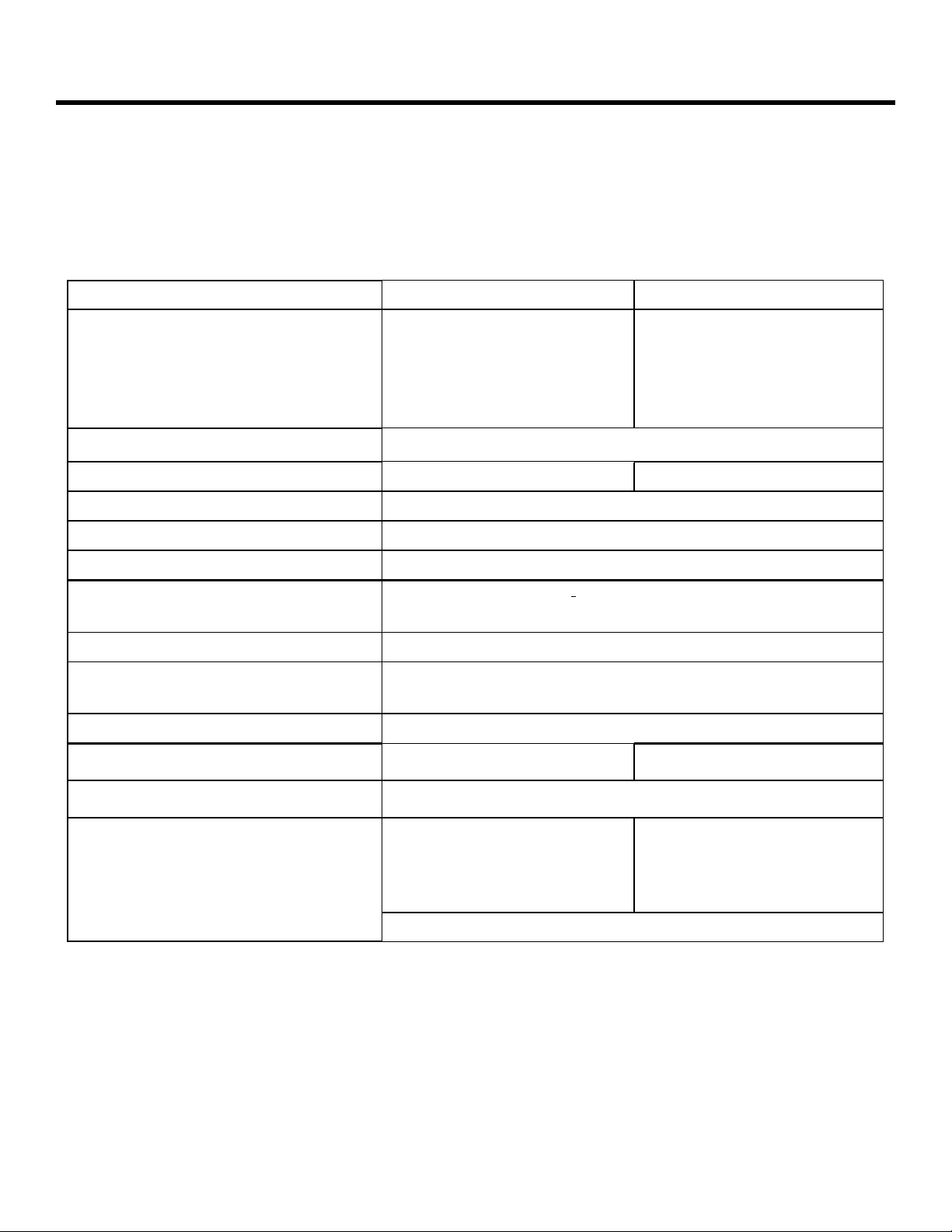
Parameter
Physical dimensions:
Weight, lb (kg) 15-1/2 lb (7.0 kg) 14-1/3 lb (6.5 kg)
Length, in. (mm) 38 7/8 in. (987 mm) 32-9/16 in (827 mm)
Width ´ height, in. (mm) 3-1/2 x 4-1/2 (90 x 114mm) 3-1/2 x 4-1/2 (90x 114 mm)
Motor speed, rpm
90-deg opening time, sec
Thrust and traction force, lb (kg) 0–1100 (0-500)
Hydraulic Locking In both opened and closed positions
Cycles per hour 30
Power voltage required, VAC
(frequency, Hz)
Current draw, amps 115v = 1.5 Amps, 230v = 1.0 Amps
Operating temperature range, deg F (deg
C)
Thermal cut out, deg F (deg C) 212 (100)
1
422 Standard 422 VHS
1400
12
115 (50–60) + 10% or 230, +6 or -10% (50–60)
-33 to 165 (-36 to 75)
6
1
Oil quantity, qt (liter)
Oil type
Gate leaf constraints
Maximum weight per leaf, lb (kg) 900 (410) 440 (200)
Maximum length per leaf, ft (m) 10 (3) 4 (1.2)
Maximum gate leaf swing, deg
Your standard 220 VAC power source meets the specification for the
required power supply of 230 VAC, +6 or –10%.
1 (0.9)
Lubrication Engineers — MONOLEC 6105
90
7/8 (0.8)
Page 5
December, 2003
422 Operator And
455 D Control Panel Installation Manual
UNPACKING THE OPERATOR
Page 5
When you receive your 422 Compact Operator,
complete the following steps.
Inspect the shipping box for physical damage such as
leaking oil or a torn carton. Then inspect the operator
after you remove it from the box. Notify the carrier
immediately if you note any damage because the
carrier must witness the damage before you can file a
claim.
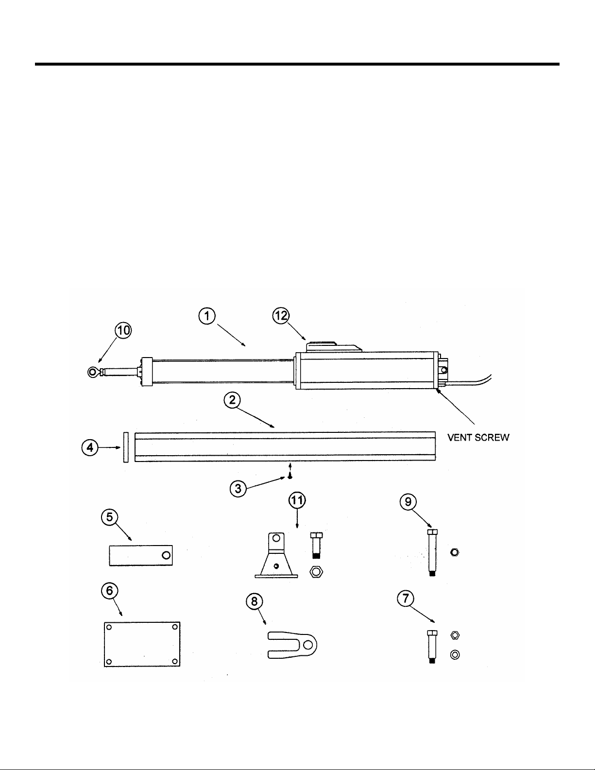
As you unpack the box, insure that all the following
parts included (see Figure 1). If you have ordered a kit
(a pair of operators), you will have twice the quantity
of parts listed below (except where noted), and you
will also have a radio receiver and two transmitters.
1 422 Operator - 1 each
2 Protective Cover - 1 each
3 Protective Cover Screw - 1 each
4 Protective Cover End Cap - 1 each
5 Rear Mounting Bracket - 1 each
6 Rear Mounting Plate (optional) - 1 each
7 Short Brass Pin with 8mm nut and washer - 1 each
8 Rear Fork - 1 each
9 Long Brass Pin with 8mm self-locking nut - 1 each
10 Swivel joint with jam nut and washer - 1 each
11 Front mounting bracket with nut and bolt
12 Locking cap cover and key for Manual Release - 1 each
Figure 1. The 422 Compact Operator
Page 6

Page 6
December, 2003
422 Operator And
455 D Control Panel Installation Manual
THE 422 COMPACT OPERATOR
GENERAL CHARACTERISTICS
The FAAC 422 Operator is an automatic gate operator
for a swinging gate leaf. It can accommodate a gate leaf
of up to 900 lb (410 kg) and up to 10 ft (3 m) in length.
The self-contained 422 Operator is an electro-hydraulic
unit consisting of an electric motor, a pump, a valve
assembly, and a hydraulic cylinder, all housed in an
anodized aluminum oil reservoir.
The 422 Operator can be used to swing the gate leaf
inward or outward. Most versions provide hydraulic
locking in at least one position, either opened or closed,
depending on how it was ordered.
The hydraulic lock is a service device rather than a
security device. Additional, external locks are
recommended under the following conditions:
• You are installing the Model 422 SB
• The length of the gate leaf is 12 ft or more
• The installation requires tight security
• The site is subject to vandalism
• The site is subject to strong or very gusty wind
• You are installing a solid face gate
For gates with two leaves, two operators are installed,
one on each leaf, and both are wired to one control
panel. In such two-operator gate installations, one leaf
can be programmed to open/ close slightly later than
the other leaf to accommodate overlapping gate
designs.
For its protection, the single-phase, bidirectional motor
shuts off automatically if its operating temperature
reaches 212 deg F (100 deg C). Also for the protection
and proper operation of the 422 Operator, each gate
leaf on which it is installed must have a fixed positive
stop in both the opened and closed positions.
The 422 Operator also includes a key-operated Manual
Release mechanism and two bypass valves that
precisely control the force applied to the gate leaf
through the 422 Operator.
The Manual Release mechanism is a key-operated
device that disengages (or engages) the hydraulic
system of the 422 Operator. When the hydraulic system
is disengaged, you can open and close the gate leaf by
hand. Such manual operation of the gate is necessary
during installation and useful during power failures.
The two bypass valves are located beneath the locking
cap. You need to adjust the bypass valves to meet the
safety standards of FAAC International, Inc. The
standards state that the gate leaf should stop if it
encounters a force of more than 33 lb (15 kg).
Additional reversing devices (such as inductive loops
and photocells) should be installed to provide more
complete protection for people and property.
The electronic control panel is a microprocessor-based
controller that accepts a wide range of product
accessories and reversing devices, thus allowing for
flexible gate system design.
INSTALLATION INSTRUCTIONS
Installing the 422 Compact Operator involves preparing
the gate, installing the operator(s), installing the control
panel, and fine-tuning the pressure adjustments on the
operator(s).
Note: The following installation instructions
assume you are fully capable of installing an
operator. This manual does not instruct you in
designing a gate, installing a gate, or basic
electrical wiring. The installation tasks discussed in
this manual are tasks particular to the 422
Operator.
PREPARING THE GATE
Before installing the 422 Operator, you need to prepare
the gate itself for the operator. Be sure to do the
following things:
1. Make sure that the gate is plumb.
2. Make sure that the gate moves smoothly on its
hinges without excessive friction by swinging
it open and closed by hand. Lubricate all the
gates’ moving parts.
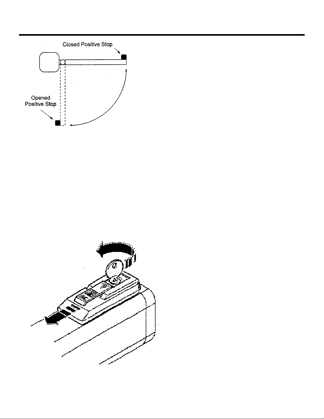
3. Provide positive stops for the gate leaves in
the fully open and fully closed positions (see
Figure 2).
Page 7
December, 2003
422 Operator And
455 D Control Panel Installation Manual
Figure 2.
Positive Stops
MANUAL RELEASE MECHANISM
For installation of the locking cap cover see page 10. To
access the keyhole, slide the key-hole cover in the
direction of the arrow (see Figure 3). Insert the key and
turn it counterclockwise one full turn to disengage the
operator’s hydraulic system. You can now move the gate
leaf slowly by hand to open or close the gate.
Operating the gate leaf by hand is necessary during
installation and is useful during power failures.
You re-engage the hydraulic system by turning the key
clockwise one full turn. Remove the key and slide the
cover closed.
Figure 3. After sliding the cover open on the Model 422,
insert and turn the key counterclockwise one
full turn to release the hydraulic system
Page 7
INSTALLING THE OPERATOR
Installing the 422 compact operator consists of the
following steps:
1. Attach the rear mounting bracket
2. Attach the mounting hardware
3. Attach the front mounting bracket
4. Attach the operator to the gate
5. Adjust the operator pressure
ATTACH THE REAR MOUNTING
RACKET
B
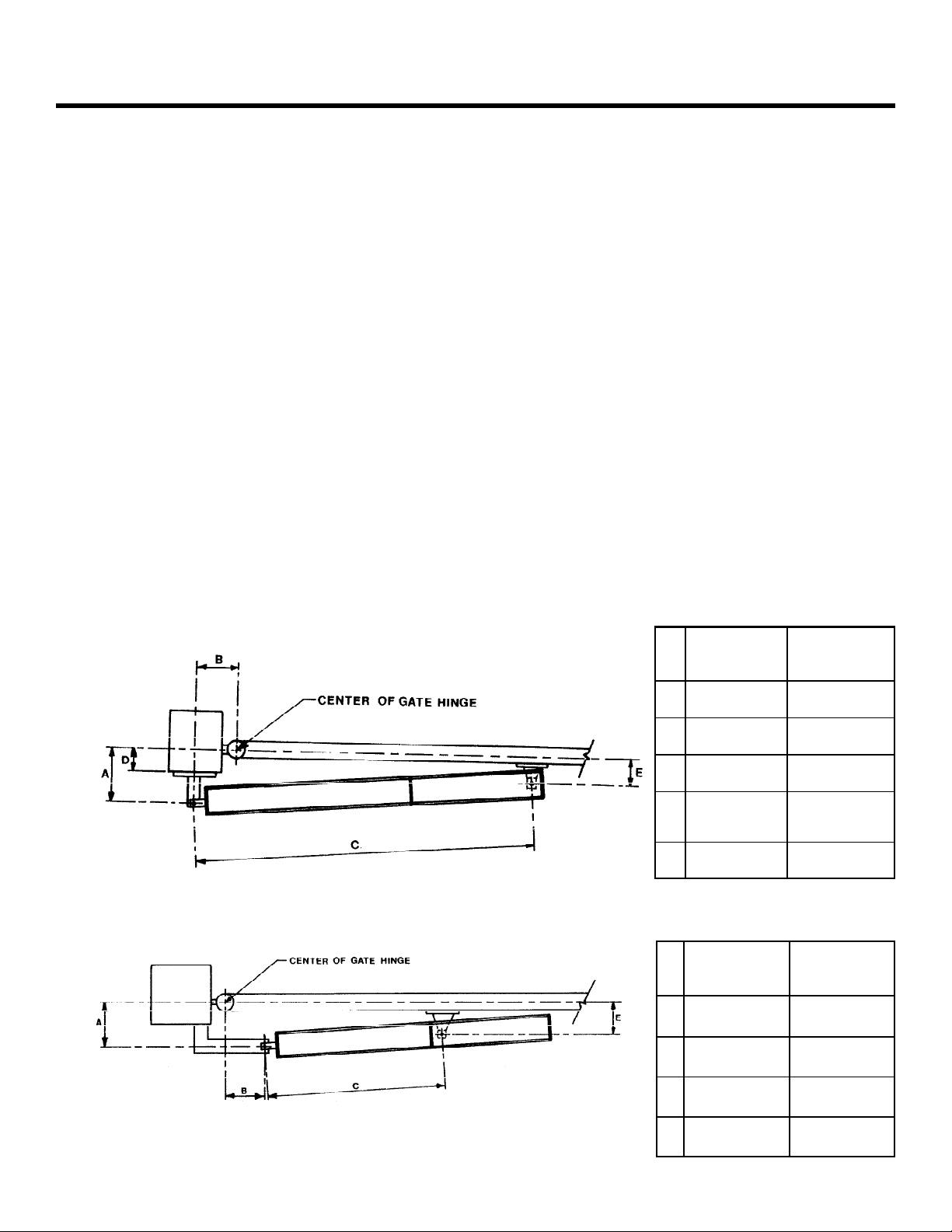
Attach the rear mounting bracket according to the
dimensions in Figure 4.
WARNING! You must achieve the A and B
dimensions, as specified in Figure 4.
Modification of the rear bracket may be
necessary to achieve these dimensions (I.e.,
cutting or extending the bracket provided)
If you have a steel gate post, weld the rear bracket
directly to it. If the gate post is made of any other
material, attach the optional mounting plate, with lag
bolts or anchors, and weld the bracket to it.
For an outward swing gate refer to Figure 5.
ATTACH THE MOUNTING HARDWARE
Insert the rear fork (hex cut up if you have a nylon rear
fork) into the rear flange of the operator. Secure with
long brass pin and self-locking nut.
Screw the jam nut onto the swivel joint. Slide the
washer on next and screw the swivel joint halfway into
the piston rod. Temporarily attach the front mounting
bracket to the swivel joint with the nut and bolt
provided.
ATTACH THE FRONT MOUNTING
RACKET TO THE OPERATOR
B
Release the operator as shown in Figure 3. Put the
operator into position and attach the rear fork to the
rear mounting bracket using the short brass pin,
washer, and nut.
For inward swing, pull the piston out completely and
push back approximately ¼” (6mm). For outward swing,
push the piston in completely and pull back out
approximately ¼” (6mm).
Note: Be sure that the operator is level and that
the gate is against the close positive stop.
Page 8
Page 8
December, 2003
422 Operator And
455 D Control Panel Installation Manual
Hold the front mounting bracket flush against the gate.
Mark the location of the front mounting bracket.
Remove the operator from the gate. Remove the front
mounting bracket from the swivel joint.
Note: Clamping the front mounting bracket at the
marked location before checking the swing, as
instructed below, will ensure proper location of the
front mounting bracket.
Bolt or weld the front mounting bracket to the marked
location on the gate.
WARNING! Do no weld the front mounting
bracket with the operator attached. Doing so will
seriously damage the operator.
ATTACH THE OPERATOR TO THE
ATE
G
Re-attach the operator to the mounting brackets. Once
the operator is mounted and level, remove the vent
screw from the bottom of the rear flange. (See Figure 1)
Use the 3mm hex key on the end of the screwdriver
provided.
WARNING! Failure to remove the vent screw
may result in erratic operation of the operator or
blown seals.
Slowly move the gate open and close.
WARNING! The piston should not bottom out in
either direction. Doing so will seriously damage
the operator.
Be sure that the gate reaches the positive stop before the
piston bottoms out. Adjust the swivel joint if necessary.
After checking the swing of the gate, secure all nuts and
bolts, including the jam nut on the swivel joint.
Once the operator is secure, install the protective cover
over the piston of the operator, first insert the two spacers
(items labeled 2 in Figure 6) in the front flange of the
operator as shown. The spacers dampen any vibrations to
the operator.
Once the protective cover is installed, swing the gate to
ensure that it does not contact the cover at any point of
the swing.
Re-engage the operator by inserting the key in the locking
cap (see Figure 3) and turning it clockwise until snug.
Remove the key.
Figure 4. An inward swinging gate, top view: important mounting dimensions
Figure 5. An outward swinging gate, top view: important mounting dimensions
422
Standard
A 4-3/4 in.
(114 mm)
B 4-3/4 in.
(114 mm)
C 36-5/8 in.
(93 cm)
D Max
2-3/4 in.
(7 cm)
E Must be
less than A
422
Standard
A 4-3/4 in.
( 12 cm)
B 4-3/4 in.
(12 mm)
C 27 in. (673
mm)
E Must be
less than A
422
VHS
3-1/8 in.
(8 cm)
3-1/8 in.
(8 cm)
29-3/4 in.
(75.5 cm)
Max
1-1/8 in.
(2.9 cm)
Must be less
than A
422
VHS
3-1/8 in.
(8 cm)
3-1/8 in.
(8 cm)
23-1/4 in.
(59 cm)
Must be
less than A
Page 9

December, 2003
422 Operator And
455 D Control Panel Installation Manual
Page 9
INSTALLING THE 455 D CONTROL
ANEL
P
Locate the control panel in the most convenient position
possible, considering the movement of the gate. Figure
9 on page 11 shows a basic layout for a two-leaf gate
with the 422 Compact Operator.
Installing the control panel consists of the following
general steps:
• Connecting the main power to the control
panel
• Connecting the activating device
• Connecting the operator to the control panel
• Checking the direction of the motor's rotation
• Connecting other devices to the control panel
• Set operating modes
The installer is responsible for grounding the gate and
operator systems, for providing the main power breaker
switch, and for making sure that the entire gate system
meets all applicable electrical codes.
For the complete 455 D Control Panel Installation
Instructions, see pages 14—25 of this manual.
Page 10

Page 10
Before reinstalling the locking cap, you must be sure
that the top of the brass key assembly in the locking
cap is flush with the top of the black plastic locking cap
(see Figure 7). If the key assembly is not flush, turn the
locking cap assembly over and press down on the unit
until the brass key assembly snaps back into place.
(a) Wrong!
Brass key assembly
December, 2003
422 Operator And
455 D Control Panel Installation Manual
BLEED THE OPERATOR
Air bubbles in hydraulic fluid cause erratic performance
in a hydraulic system, so you must rid the 422 Operator
of that air to insure smooth operation.
If you have removed the vent screw, the 422 operator
should bleed itself. Running the operator should remove
any air from the system. If the operator runs smooth
throughout the swing, no attempt to further bleed the
unit is necessary.
If the operator runs erratic, perform 10 bleeding operations. One bleeding operation consists of automatically
opening and closing the gate and then pausing for two
minutes. The 2-min pause allows the air bubbles to escape through the vent screw hole.
Black plastic locking
cap assembly
(b) Correct!
Brass key assembly
Black plastic locking
cap assembly
Figure 7. The brass key assembly in relation to the black
plastic locking cap, side view: (a) do not install in this
orientation and (b) install the locking cap only when the top
of the brass key assembly is flush with the black plastic
housing of the locking cap assembly.
WARNING! If the brass key assembly is not
properly seated in the locking cap assembly,
you risk damaging, even eliminating, the
Manual Release function of the operator.
Next, reinstall the locking cap (without the key) with
your 3 mm hex key and the two screws.
Now you can install the locking cap cover as shown in
Figure 8. Snap the cover on before you attempt to slide
the entire cover in the direction of the arrow. If the
cover does not snap into place, you are unable to slide
the cover into position.
Figure 8. Install the locking cap cover
Page 11

December, 2003
422 Operator And
455 D Control Panel Installation Manual
Page 11
Figure 9. The layout of a sample gate system
6
1
5
3
A
A
Locate switches at least
10 ft from the gate
2
8
1
A
4
5
C
B
3
7
B
A
C
D
9
1 Operator Wire Gauges for Given Voltage
2 Control Panel 220 VAC 115 VAC
3 Photocell A 2 × 18 AWG A 2 × 18 AWG
4 Switch B 4 × 14 AWG B 4 × 14 AWG
5 Junction box (see text) C 5 × 18 AWG C 5 × 18 AWG
6 Reversing edges D 4 × 14 AWG up to 414 ft D 3 × 14 AWG up to 130 ft
7 Gate stops
8 Switch
9 Wiring to main circuit breaker
3 × 10 AWG up to 340 ft
Page 12

Page 12
December, 2003
422 Operator And
455 D Control Panel Installation Manual
EXPLODED VIEW, 422 CBC
Page 13

December, 2003
422 Operator And
455 D Control Panel Installation Manual
422 PARTS LIST
Page 13
POS PART NO. DESCRIPTION QTY
1 2036 Galvanized Nut (8mm) 1
2 7220015 Rear Bracket 1
3 7284005 Rear Bracket Plate 1
4 7182075 Short Pin 1
5 7221115 Rear Fork 1
6 2037 Self-Locking Nut (8mm) 1
7 7170595 Rear Flange 1
8 7099101 Gasket (D80) 2
9 7090440 O-Ring Locking Cap (Small) 2
10 7090655 O-Ring Locking Cap (Center) 1
11 41850215 Locking Cap 1
12 7094065 Gasket (copper) 3
13 2274 Vent Screw (4x6mm) 3
14 7270805 Locking Cap Cover 1
15 7270815 Access Slide (Locking Cap) 1
16 7131005 Viro Key (Manual Release) 1
17 N/A Self Threading Screw 1
18 7119475 Vibration Dampener 2
19 2365 Motor Bolt (4X50mm) 4
20 2366 Lock Washer 4
21 2367 Hex Nut (4mm) 4
22** 77000425 115V 1400 RPM Motor 1
23 7119485 Vibration Dampener 2
24 309005 Operator Body 1
25 N/A Vent Screw Label 1
26 7182175 Long Pin 1
27 2274 Vent Screw 3
28 N/A Torx (Self Threading) T20 8
29 7514055 Electric Power Cord 1
30* 2581 Fiber Washer 1
31* 7039305 Strain Relief Brass Washer 1
32* 7109155 Strain Relief Nut 1
33* 7109145 Strain Relief 1
34 3204395 1Lt Lobe Pump 1
35 N/A Pump Pin 2
36 760285 Spacers (Protective Cover) 2
37 4900605 Swivel Joint 1
38 7271545 Protective Cover End Cap 1
39 7114025 Protective Cover Plug 1
40 7272125 Protective Cover 1
41 7220515 Front Mounting Bracket 1
42 4900605 Swivel Joint Kit 1
POS PART NO. DESCRIPTION QTY
43 N/A Self Threading Screw 1
44 7090010015 O-Ring 3
101 7090050015 O-Ring 6
102 7049135 Valve Retainer 2
103 4404065 Inlet Valve 2
104 4180035 Red By-Pass Cap Assembly 1
105 4180045 Green By-Pass Cap Assembly 1
106 7119015 By-Pass Cap (Red) 1
107 7210025 By-Pass Spring 2
108 7310315 By-Pass Cap 2
109 7119115 By-Pass Cap (Green) 1
110 7090280015 O-Ring Retract Tube (Short) 3
111 7043055 Extrusion Ring 1
112 4180195 Manual Release 1
113 7090360 O-Ring (Valve Body) 1
114 7361035 Retract Tube (Short) 1
115 7090350 O-Ring (Mid Flange) 2
116 7090665 O-Ring Retract Tube (Long) 2
117 7361315 Retract Tube (Long) 1
118 7230225 Tie-Rod (Cylinder) 4
119 N/A O-Ring Front Flange (Internal) 1
120 N/A Star Washer 4
121 4994165 Front Flange 1
122 4350085 Piston Assembly 1
123 7095035 Piston Rod Packing 1
124 7366065 Cylinder 1
125 7271555 Protective Cover Guide 1
126 499449 Mid Flange 1
127 4404085 Lock Valve 2
128 4180285 Shuttle Piston 1
129 7090300 O-Ring (Shuttle Piston) 1
130 N/A Galvanized Washer 4
131 N/A Galvanized Screw 4
132 4994345 Valve Body (CBAC) 1
133 7049005 Valve Retainer (Brass) 2
134 3905255 Skin Pack 1
135 2172* Seal Kit 1
136 6105 1 Qt Monolec Oil 1
∗ Included in Kit #2167A*
∗ * 220V 1400RPM Motor Part #77000415
Page 14

Page 14
December, 2003
422 Operator And
455 D Control Panel Installation Manual
THE 455 D CONTROL PANEL
GENERAL DESCRIPTION
The FAAC 455 D control panel is used to operate the
following models.
Swing gate operators:
400 412
402 750
422 760
Barrier gate operators:
610/615
The 455 D programming controls the following:
Operating logic: A, S, E, EP, B, and C logics
available.
Reversing device behavior: Choose whether a
triggered reversing device during closing
immediately reverses gate movement or stops
the gate and reverses gate movement when no
longer triggered.
Torque or Pressure: Force adjustment for the
412 operator. Adjustable from 0 to 50.
Caution: For all hydraulic operators, the torque
must be programmed to the maximum (50)
setting.
Pause time between opening and closing:
adjustable from 0 to 240 seconds.
Opening/Closing time: adjustable
from 0 to 120 seconds.
Leaf delay on closing: adjustable from 0 to 28
seconds.
The 455 D control panel should be installed in an
enclosure that is conveniently located as close as
possible to the gate operator. All electrical
connections from the control panel to the operator
must be made in a weatherproof junction box.
The 455 D control panel requires a single-phase
power supply voltage (115 VAC [±10%] or 230 VAC
[+6 or -10%], 50–60 Hz). The power supply should be
protected by a 15 amp dedicated circuit breaker (not
provided).
The installer is responsible for grounding the
operator system, for providing the main power
breaker switch, and for making sure that the entire
gate system meets all applicable electrical codes.
The installer should refer to the installation manual
for a given operator for more information.
N
OTE: An installation is U.L. compliant only
when you install the FAAC operators according
to the UL325 standards.
INSTALLING THE 455 D CONTROL
ANEL
P
Locate the control panel in the most convenient position
possible, considering the movement of the gate.
Installing the control panel consists of the following
general steps:
• Connecting the main power to the control
panel
• Connecting the activating device
• Connecting the operator to the control panel
• Checking the direction of the motor's rotation
• Connecting other devices to the control panel
• Set operating modes
CONNECT THE MAIN POWER SUPPLY
WARNING! Turn the main power off before you
make any electrical connections or before
programming.
Wire the main power supply to control panel terminals
in block J3 (see Figures 11 and 12). The installer is
responsible for insuring that a separate, grounded
circuit protected by a circuit breaker is between the
control panel and the main power supply. All wiring
should conform to applicable electrical codes, and all
wiring and fittings should be weatherproof and/or
suitable for burial.
Connect the ground to the grounding terminal in block
J3 and connect the power wires to the terminals labeled
N (neutral) and L (line).
N
OTE: For a 230V system, a neutral is not
needed. Connect one 115V line to the L (Line)
and a second 115V line to the N (Neutral).
THE 455 D CONTROL PANEL INSTALLATION INSTRUCTIONS
Page 15

December, 2003
422 Operator And
455 D Control Panel Installation Manual
Page 15
CONNECT THE OPERATOR(S) TO THE
ONTROL PANEL
C
WARNING!
you make any electrical connections or before
programming.
CAUTION: The operators are grounded only by
the grounded circuit the installer provides.
USING A JUNCTION BOX
If an operator is more than 2 ft away from the control
panel, you must use a junction box for connection.
Use a U. L. Listed cord grip where the operator cord
enters the junction box.
Note: If you have a one-leaf gate design, the
operator must be connected to Motor 1
(terminals 1,2, & 3)
To wire up motor 1, connect the white wire to
terminal 1(on the J4 terminal strip), the black wire to
2, and the red wire to 3. Wire each leg of the capacitor
(supplied) to terminals 2 & 3.
Note: If you want to delay the closing of one gate
leaf in a two-leaf gate design, be sure to connect
its operator to Motor 1.
Turn the main power off before
In order to wire motor 2 in a bi-parting system,
connect the white wire to terminal 4 (on the J4
terminal strip), the black wire to 5, the red wire to 6.
Wire each leg of the capacitor (supplied) to terminals
5 & 6.
CHECK THE MOTOR’S DIRECTION OF
OTATION
R
After you have connected the main power supply, and
the operator(s) to the control panel, you need to
check the direction of rotation for each operator
motor in your gate design.
Note: To check a motor’s direction of rotation,
you must have three closed circuits on terminal
block J1. Install one circuit between terminals 11
and 16, another circuit between terminals 12
and 19, and another circuit between terminals
13 and 19.
THE 455 D CONTROL PANEL INSTALLATION INSTRUCTIONS
J3
K
1-455D115 = 115V
1-455D = 230V
M
N L
MAIN
Figure 10. The 455 D Control Panel
MOTOR 2
M
LAMPCOMOP CL
CLCOMOP
F1
1 2 3 4 5 6 7 8
MOTOR 1
F2
J4J5J1
9 10 11 12 13 14 15 16 17 18 19
NC -B -
A + TX
STOP
V1- 4
61C455D
J3 terminal block for
main power supply
J4 terminal block for
connecting the operator(s)
J1 terminal block for low-
J2
voltage accessories
F-+
RADIO
J2 quick connector port
F Function Push Button
— Programming Push
Button
+ Programming Push
Button
FUSES
J6
22 23 24 25
20 21
FCA 1
FCA 2
+OP -CL
+24 VFSW
FS W
W. L.
LOCK
FCC1
F1
Main Power
FCC2
F2
Accessories
220
VAC
5 A 10 A
800
mA
115
VAC
800
mA
Page 16

Page 16
December, 2003
422 Operator And
455 D Control Panel Installation Manual
N L
115 VAC +/- 10%
or
230 VAC +6/ -10%
50-60 Hz
1 2 3 4 5 6 7 8
MOTOR 1
BLUE
M1
OPCOM CL
C1
OPCOM CL
MOTOR 2
BLUE
M2
C2
Figure 11.
The terminal strip wiring of the
455 D with photobeams
NOTE: In orde r to comply with U L 3 2 5, two se ts
of FAAC photobeams m ust be installed. One set
shoul d be 6 i n. outsi d e the clos e d gate(s) and act
as a c losing reversing devic e. Another set should
be 6 in. bey ond the swing of the gate(s) and act
as an opening reversing dev i ce. The installer is
responsible for determ ini ng the appropriate
mounting hei ght.
You cannot check the motor’s direction of rotation
without these circuits (jumpers) or the accessories.
When properly prepared for testing, the LEDS FSWOP,
STOP, and FSWCL should be illuminated (see figure 13
on page 17).
WARNING! Running the operator—even for
testing purposes—without a connected reversing
device is potentially dangerous. Do not place
yourself within the path of the moving gate
during your test.
Disengage the operator(s) with the Manual Release
key (see operator installation manual), and open the
gate by hand about halfway.
Next, engage the operator(s) with the Manual Release
key so that you can check the rotation of the motor
(s).
To activate the operator(s) momentarily short across
terminals 9 and 14.
Turn on the main power and send an activating signal
to the operator. The gate leaf (or leaves) should open.
If a gate leaf closes, then you need to turn off the
main power and reverse the connection of the red
and black wires on terminal block J4 for the operator
controlling that leaf. Then you need to recheck the
rotation direction again.
After having completed your test of the motor’s
direction of rotation, replace any test circuits you
installed (between terminals 11 and 16, between 12
and 19, and between 13 and 19) with the proper
reversing and stop devices. The instructions for
installing such accessories follow.
THE 455 D CONTROL PANEL INSTALLATION INSTRUCTIONS
9 10 11 12 13 14 15 16 17 18 19
LAMP
STOPOPE N OPEN
(1 of 2 )
-
OPCL -
FS W
CONNECT OTHER DEVICES
WARNING! Turn the main power off before you
make any electrical connections.
POWER SUPPLY FOR ACCESSORIES: You can access a 24
VDC output for supplying power to accessories
through terminals 17 or 18, (+) and 14 or 15 or 16, (-)
on terminal block J1. In most cases, this source can be
used to power 24 VDC accessories.
NOTE: The 455 D control panel allows a
maximum accessory load of 800 mA.
R
EVERSING DEVICES: Reversing devices include
photocells, inductive loops, and so forth. All of the
reversing devices should have contacts of the normally
closed (N.C.) type. Where you connect a device
depends on whether you want the device to operate
during opening or during closing.
N
OTE: UL does not recognize the FAAC system
with loop detectors or safety edges. FAAC
photobeams must be used to comply with UL 325.
To wire photobeams, refer to page 19 (see FSWOP for
opening photobeams, and FSWCL for closing
photobeams). Photobeams must be connected as
shown. See also page 19 for the wiring of inductive
loops. If using more than one reversing device, they
must be wired in series.
- - +
Other safeties
1
2
3
4
5
1
2
+
24V
FS W OP
FS W C L
FS W
20 21
W.LIGHT
24 vdc
3 W
1
2
1
2
3
4
5
22 23 24 25
LOCK
ELECTRIC LOCK
Page 17

December, 2003
422 Operator And
455 D Control Panel Installation Manual
To the U. L. Listed gate operator
(a)
U.L. Listed Control Panel Enclosure
(b)
Page 17
U.L. Listed
cord grip
Junction box
Legend
Figure 12.
Wiring detail (a) inside
the junction box and (b)
from the junction box or
operator to the high-
voltage terminal strip on
White
Red
Black
Yellow/
Green
the 455 D control panel
Conduit to U.L. Listed
To the U.L. Listed
control panel
control panel enclosure
according to N.E.C.
ACTIVATING DEVICES AND RADIO RECEIVER: The
activating devices and radio receiver for your gate must
have normally open (N.O.) contacts. Connect such
devices to terminals 9 and 14.
N
OTE: The FAAC radio receiver plugs into the 5
prongs labeled J2 (Quick connect port).
Page 19 shows how to connect a three or four wire
receiver.
DECODER CARD: If you are installing the Digicard
magnetic card reader, or the Digikey keyboard, use the
quick-fit connector J2 for the DS decoder card (see
Figure 10).
N
OTE: If your using both a receiver and decoder,
hard wire the decoder and plug in the receiver.
OPEN/HOLD OPEN DEVICE: To open and hold open the
gate, simply maintain a contact across terminals 9 and
14. (“A” Mode only)
STOP BUTTON: The stop button you install must have
normally closed (N.C.) contacts. Multiple stop buttons
must be wired in series. Connect your stop device
between terminals 11 and 16.
N
OTE: The 455 D will not operate the motors
without a closed circuit between 11 & 16.
The LED Indicators: The nine light emitting diodes
(LEDs) on the control panel can be used to check for the
proper function of the devices attached to the panel.
The LED lights are on whenever the contacts are closed
across each of the respective terminals.
OP_A and OP_B (Partial Opening) should illuminate only
when an activating signal is sent for 2 and 1 gate leaves,
respectively. STOP should be illuminated except when
the stop button is pressed. FSWOP and FSWCL should be
illuminated except when the reversing devices, for
Cord grip or
conduit from
U.L. Listed gate
operator(s)
LED On Off
OP_A Command Given No Command
OP_B Command Given No Command
Stop No Command Command Given
FSW
Open
FSW
Close
FCA1
Opening reversing
devices clear
Closing reversing
devices clear
Flashes when gate coder is in use.
FCC1
FCA
2
Flashes when gate coder is in use.
FCC
2
FSWOP
OP_A
STO P
OP_B
FSWCL
FCA1
FCA2
This display shows the
meaning of each LED.
Figure 13. The 455 D display.
455 D Control Panel
High-voltage
terminal strip
J3 J4
COM OP CL COM OP CL
Op.1 Op.2
J1
Ground
Reversing device
triggered
Reversing device
triggered
Operator 1
Operator 2
FCA1
FCC1
FSWOP
OP_A
STOP
FCC2
OP_B
FSWCL
FCA2
This display shows the normal
status of the control panel.
THE 455 D CONTROL PANEL INSTALLATION INSTRUCTIONS
FCC1
FCC2
Page 18

Page 18
December, 2003
422 Operator And
455 D Control Panel Installation Manual
opening and closing, respectively, are triggered. Use
the LEDs and the next table to determine if the
accessory devices you have installed are operating
properly.
Electric Locks: An electric lock can be wired to
the 455 D in
provided). If a reversing stroke is needed to allow the
electric lock to release, this must be done in advanced
programming.
See page 19 for the connections for a magnetic locking
device.
terminals 18 and 21 (12Vac pulsed
WARNING LIGHT: Connect a warning light to
terminals 18 and 20 in the group labeled W.LIGHT
in terminal block J1 and J5. The terminals provide
an output voltage of 24 VDC, maximum power 3
Watts. This output voltage will power most 24 VDC
warning lights.
N
OTE: The behavior of the warning light varies
according to the logic you have set.
LOGICS A, S, E, EP, AND B: The warning light is on
steadily during opening and the pause phase. During
closing, the light flashes.
LOGIC C: The warning light is on steadily during
opening and flashes during closing.
SET OTHER OPERATING CONTROLS
WARNING
make any electrical connections.
You need to program the control panel for your gate's
operation. The 455 D Control Panel has on board
programming that controls a wide range of functions.
OPERATING LOGICS
NOTE: The 455 D Control Panel provides inputs
for opening reversing devices and closing
reversing devices. FAAC strongly recommends
the use of reversing devices, such as photocells
or other non-contact sensors.
•
A (automatic): The gate opens on command
and automatically closes after a pause phase. A
second command while opening is ignored; a
second command during the pause phase
interrupts the pause time; a second command
during closing reopens the gate. A maintained
open command will hold the gate open.
•
S (security): The security mode is like A logic
except that a second command during opening
immediately closes the gate. A maintained
THE 455 D CONTROL PANEL INSTALLATION INSTRUCTIONS
open command will not hold the gate open.
! Turn the main power off before you
• E (semi-automatic): This mode requires a
command to open and a command to close.
A second command during opening stops the
gate. A second command during closing
reopens the gate.
•
EP (semi-automatic, step by step): This
mode requires a command to open and a
command to close. A second command
during opening or closing causes the gate to
stop. A third command then reverses the
previous motion of the gate.
•
B (manned, pulsed): This mode is designed
for guard station use and requires a threebutton switch (pulsed) to open, close, and
stop the gate.
•
C (manned and constant): This mode
requires constant pressure switches. One to
open and one to close. No pressure on a
switch stops the gate.
The three programming push buttons allow the
programming of the torque (or pressure), the pause
time between opening and closing, and the leaf delay
on closing.
WARNING! Turn the main power off before you
make any electrical connections.
For all FAAC hydraulic operators using the 455 D
control panel, the force must be set at its maximum
setting of 50 in order to supply the correct voltage to
the operator.
PAUSE TIME: The pause time between opening and
closing can be adjusted from 0 seconds to 4 minutes.
Time is adjusted in one-second increments from 0—
59 seconds. When 60 seconds is reached, time is
adjusted in 10 second increments up to 4 minutes.
i.e. if display shows 2.5, it means 2 minutes and 50
seconds.
LEAF DELAY: You may choose to delay one leaf on
closing for overlapping gate leaves. Be sure the
operator on the leaf for delayed closing is connected
to Motor 1. On opening, the leaf connected to Motor 2
is delayed 2.5 sec.
N
OTE: If an opening leaf delay is desired, it must
be enabled in the Advance Programming.
However, if enabled, you cannot adjust this
opening delay of the operator connected to
Motor 2.
The closing leaf-delay time is adjustable from 0 to 4
minutes.
NOTE: If the opening/closing time is set at less
than the leaf delay time, the delayed leaf closes
at the end of the closing time.
Page 19

December, 2003
422 Operator And
455 D Control Panel Installation Manual
Page 19
Free Ex it Loop/ Phone/ F ireb ox
(Hold Open D ev ices )
9
14
FAAC
Rev ersing Phot oc ells
(for ope ning)
Additional
Reversing Devices
19
17
13
14
17
Magnetic Loc k
THE 455 D CONTROL PANEL INSTALLATION INSTRUCTIONS
-
Lock
+
17
NO
C
14
18
21
Shadow Loop
1
TX
2
1
2
3
RX
4
5
19
12
Additional
Reversing Devices
7
8
12 vac
Relay
N.C.
N.O.
COM
Coil Volt age =
Mot or V olt age
N.C.
N.O.
COM
C
NC
Additional
Reversing Devices
19
17
12
19
17
Reversing Devices
19
12
15
17
FAAC
Rev ersing Phot oc ells
(for c los ing)
FAAC
Safet y Loop
Additional
Detector
(for c los i ng)
3 & 4 Wire R adio R ec eiv ers
1
TX
2
14
1
2
3
RX
9 NO
14
17
If 4 Wire Receiver
C
-
+
4
5
Safet y Series
Wiring
1
TX
2
PHOTO-BEAMS
RX
LOOP
DETECTOR
(FAAC)
FAAC
1
1
2
7
8
19
17
12
14
17
2
3
4
5
1
2
7
8
NO = Normally Open, NC = Normally Closed, C = Common, TX = Transmitter, RX = Receiver
Figure 14. Common Accessories wired to 455 D Control Panel
Page 20

Page 20
December, 2003
422 Operator And
455 D Control Panel Installation Manual
PROGRAMMING
To program the automated system, the
“Programming Mode” must be accessed.
Programming is split into two parts: BASIC and
ADVANCED.
BASIC PROGRAMMING
To access BASIC PROGRAMMING, press the “F” key.
• If you press it (and hold it down), the display
shows the name of the first function.
• If you release the key, the display shows the
value of the function that can be modified with
keys + and — .
• If you press and hold down the “F” key again
(and hold it down), the display shows the name
of the next function, etc.
• When you reach the last function, press “F” to
exit the program, and the display resumes
showing the status of the inputs.
The table on the right shows the sequence of
functions accessible in BASIC PROGRAMMING.
ADVANCED PROGRAMMING
To access ADVANCED PROGRAMMING, press the “F”
key and, as you hold it down, press the “+” key:
• If you release the “+”, the display indicates the
name of the first function.
• If you release the “F” key, too, the display
shows the value of the function that can be
modified with keys “+” and “—”.
• If you press the “F” key (and hold it down), the
display shows the name of the next function,
and if you release it, the value that can be
modified with keys “+” and “—”.
• When you reach the last function, press the “F”
key to exit the program, and the display
resumes showing the status of the inputs.
The table on page 9 shows the sequence of
functions accessible in ADVANCED
BASIC PROGRAMMING
F
Display Function Default
O
PERATING LOGICS
A = Automatic (Timer to Close)
E = Semi Automatic
S = Security
EP = (Semi-Automatic) Step by Step
B = Manned, Pulsed
C = Manned, constant
AUSE TIME
P
This is the time between open and
closing and is adjustable from 0 to
4 min. This is only true in “A”
Mode. (see pause time description)
F
ORCE/TORQUE MOTOR 1
This adjusts the force / torque that
motor 1 is applying to the gate
leaf. Setting is 0 to 50.*
F
ORCE/TORQUE MOTOR 2
This adjusts the force / torque that
motor 2 is applying to the gate
leaf. Setting is 0 to 50.*
C
LOSING LEAF DELAY
Delays the closing of operator
wired into motor one outputs. Adjustable from 0 to 4 minutes
(Same as pause time)
M
OTOR RUN TIME
This enables where you choose
from “simple” learning or
“complete” learning of the motor
run time. See page 10 & 11 for
complete details.
Simple Learning
+
~ 1 s.
Complete Learning
+
> 3 s.
THE 455 D CONTROL PANEL INSTALLATION INSTRUCTIONS
PROGRAM BUTTONS
+ -
LEFT MIDDLE RIGHT
F
* With Hydraulic operators the Force/Torque must be set to
the maximum setting of 50.
XIT PROGRAMMING
E
Exit from programming and return
to display of inputs status.
Page 21

December, 2003
422 Operator And
455 D Control Panel Installation Manual
Page 21
ADVANCED PROGRAMMING
+
F
+
Display Function De-
fault
M
AXIMUM TORQUE AT INITIAL
T
HRUST: The motors operate at
maximum torque (ignoring the
torque setting) at start of movement.
Useful for heavy leaves.
4 = Enable
No = Disabled
L
AST STROKE AT CLOSING:
The motors are activated at full
speed for 1s to facilitate locking of
the electric lock.
4 = Enable
No = Disabled
R
EVERSING STROKE:
Before opening, while the gate is
closed, the motors thrust to close
for 2 s thus facilitating release of the
electric lock.
4 = Enable
No = Disabled
L
EAF 2 OPENING DELAY (2S):
Enables delayed start (at opening) of
leaf 2, avoiding interference between
leaves.
4 = Enable
No = Disabled
F
AIL SAFE:
If this function is activated, it enables a function test of the photocells before any gate movement. If
the test fails (photocells not serviceable), the gate does not start the
movement.
4 = Enable
No = Disabled
P
RE FLASHING (5S):
Activates the flashing lamp for 5s
before start of movement.
4 = Enable
No = Disabled
E
LECTRIC LOCK ON LEAF 2:
For using the electric lock on leaf 2
instead of on leaf 1.
4 = Enable
No = Disabled
Display
Function De-
fault
I
NDICATOR-LICHT:
If 0 is selected, the output functions
as a standard indicator-light (lighted
at opening and pause, flashing at
closing, and off when gate closed).
Different figures correspond to timed
activation of the output, which can be
used (via a relay) to power a courtesy
lamp. Time can be adjusted from 0
to 59s in 1s increments, and from 1.0
to 4.1 min. in 10s steps.
0 = Standard Indicator-Light
From 1 to 4.1 = Timed Output
C
LOSING PHOTOCELLS REVERSE AT
RELEASE: Enable this function if you
want the closing photocells to stop
the gate movement and reverse it
after the beam is cleared. Default setting is immediate reverse.
4 = Enable
No = Disabled
A.D.M.A.P. F
If this function is enabled, the safety
devices operate in compliance with
French standard NFP 25/362.
A
SSISTANCE REQUEST (COMBINED
WITH NEXT FUNCTION): If activated,
at the end of countdown (settable
with the next function, i.e. “Cycle programming”) it effects 8s of preflashing at every Open pulse (job request). Can be useful for setting
scheduled maintenance jobs.
C
YCLE PROGRAMMING:
For setting count down of system
operation cycles. Settable (in thousands) from 0 to 99 thousand cycles.
The displayed value is updated as
cycles proceed. This function can be
used to check use of the board or to
exploit the “Assistance Request” function
.
XIT PROGRAMMING:
E
Exit from programming and return to
display of inputs status.
UNCTION:
4 = Enable
No = Disabled
4 = Enable
No = Disabled
THE 455 D CONTROL PANEL INSTALLATION INSTRUCTIONS
Page 22

Page 22
December, 2003
422 Operator And
455 D Control Panel Installation Manual
LEARNING OF OPERATING TIMES
WARNING:
safety devices are disabled
all traffic must be avoided in the path of the gate
leaf(s).
During the learning procedure, the
! Therefore, any and
NOTE: Programming must start with the gate(s)
in the closed position.
Opening/closing time is established by the learning
procedure which varies slightly according to whether
you are or are not using Gatecoders.
LEARNING OF NORMAL TIMES
Normal learning (i.e. without Gatecoders) can be done
in two different ways:
SIMPLE LEARNING (WITHOUT SLOW DOWN)
Close the gates, enter “B
TIME LEARNING function and press the + push-button
for 1 second the display begins flashing and the
leaves begin the opening movement.
Wait for the leaves to reach the opening positive stop
and then supply an OPEN A command after the
desired motor run time has been reached (by pushbutton or radio control) to stop the movement: the
leaves stop and the display stops flashing. One more
command given will close the gate.
The procedure has ended and the gate is ready to
operate.
COMPLETE LEARNING (WITH SLOW DOWN)
NOTES:
•
If you do not wish to slow the gate operator
(s) down, wait for the gate to reach its
positive stop and supply two (2) consecutive
open commands (within 1 second).
• If only one gate operator (1) is used, you
must go through the entire programming
procedure, as if you were programming for
two gate operators (2). When the operator
has finished opening, supply 5 open
commands until the gate operator begins to
close, and then resume normal operations.
Close the gates, enter “B
TIME LEARNING function and press the + push-button
for more than 3 seconds: the display begins flashing
and leaf 1 begins opening. The following functions
can be commanded by the OPEN A (by push-button
wired to terminals 9 and 14, or radio control):
THE 455 D CONTROL PANEL INSTALLATION INSTRUCTIONS
ASIC PROGRAMMING”, select the
ASIC PROGRAMMING”, select the
• When gate operator (1) reaches the position
that you want it to slow down, an open
command must be given to start the slow
down phase.
• When gate operator (1) reaches the positive
stop and the desired motor run time has
been reached, an open command must be
given to shut the motor off. At this point
gate operator (2) will automatically start to
open.
• When gate operator (2) reaches the position
that you want it to slow down, an open
command must be given to start the slow
down phase.
• When gate operator (2) reaches the positive
stop and the desired motor run time has
been reached, an open command must be
given to shut the motor off. At this point
gate operator (2) will automatically start to
close.
• When gate operator (2) reaches the position
that you want it to slow down, an open
command must be given to start the slow
down phase.
• When gate operator (2) reaches the positive
stop and the desired motor run time has
been reached, an open command must be
given to shut the motor off. At this point
gate operator (1) will automatically start to
close.
• When gate operator (1) reaches the position
that you want it to slow down, an open
command must be given to start the slow
down phase.
• When gate operator (1) reaches the positive
stop and the desired motor run time has
been reached, an open command must be
given to shut the motor off.
The display stops flashing and the gate is ready for
normal operation.
LEARNING TIMES WITH GATECODER
Learning with the Gatecoder can be done in two
different ways:
SIMPLE LEARNING
Close the gates, enter “Basic Programming”, select the
TIME LEARNING function and press the + push-button
for 1 second: the display begins flashing and the
leaves begin the opening movement.
The movement stops automatically when the opening
positive stop is reached and the display stops
flashing.
Page 23

December, 2003
422 Operator And
455 D Control Panel Installation Manual
Page 23
The procedure has ended and the gate is ready to
operate, using default slow down automatically set
by the control panel.
COMPLETE LEARNING
NOTES:
• If only one gate operator (1) is used, you
must go through the entire programming
procedure, as if you were programming a
gate operator (2). When the gate operator
(1) has finished opening, supply 5 open
commands until the gate operator begins
to close, and then resume normal
operations.
Close the gates, enter “B
the TIME LEARNING function and press the + pushbutton for more than 3 seconds: the display begins
flashing and leaf 1 begins opening movement. The
following functions can be commanded by the OPEN
A command (by radio control or key push-button):
• When gate operator (1) reaches the
position that you want it to slow down, an
open command must be given to start the
slow down phase. When the gate operator
reaches its positive stop, the operator will
automatically shut off.
• An open command must be given to start
opening gate operator (2).
• When gate operator (2) reaches the
position that you want it to slow down, an
open command must be given to start the
slow down phase. When the gate operator
reaches its positive stop, the operator will
automatically shut off.
• An open command must be given to start
closing gate operator (2).
ASIC PROGRAMMING”, select
THE 455 D CONTROL PANEL INSTALLATION INSTRUCTIONS
• When gate operator (2) reaches the position
that you want it to slow down, an open
command must be given to start the slow
down phase. When the gate operator reaches
its positive stop, the operator will
automatically shut off.
• An open command must be given to start
closing gate operator (1).
• When gate operator (1) reaches the position
that you want it to slow down, an open
command must be given to start the slow
down phase. When the gate operator reaches
its positive stop, the operator will
automatically shut off.
The display stops flashing and the gate is ready for
normal operation.
NOTES:
• The open command to slow down the gate
should be given before the gate reaches the
positive stop to prevent the gate from hitting
the stop at full speed. The positive stop could
be mistaken for an obstacle and then upon
hitting it, the gate(s) would automatically
reverse on contact.
AUTOMATED SYSTEM TEST
When you have finished programming, check if the
system is operating correctly.
Most important of all, check that the force is adequately
adjusted and that the safety devices are operating
correctly.
If pressure adjustments on hydraulic operators are not
set before programming. It may need to be
reprogrammed for desired results.
Page 24

Page 24
December, 2003
422 Operator And
455 D Control Panel Installation Manual
A (Automatic) Logic (455 D)
Gate Status Open A Open B Stop Opening
Opens single leaf
connected to Motor
1 and closes it after
pause time
Interrupts the
pause time
No effect No effect No effect Off
Stops No effect
No effect
(opening is
inhibited)
Closed
Opening
Opened
Closing
Stopped
Opens both leaves
and closes them
after pause time
No effect No effect Stops
Interrupts the
pause time
Opens both leaves Opens leaf Stops No effect
Closes the leaves Closes the leaf
Reversing
Device(s)
Stops; gate closes
when reversing device no longer trig-
gered
No effect
S (Security) Logic (455 D)
Gate Status Open A Open B Stop Opening
Opens single leaf
connected to Motor
1 and closes it after
pause time
No effect No effect No effect Off
Closed
Opening
Opens both leaves
and closes them after
pause time
Closes both leaves Closes leaf Stops
Reversing
Device(s)
Stops; gate closes
when reversing device no longer trig-
gered
Closing
Reversing
Device(s)
No effect On
Gate remains open
until reversing devices
no longer triggered
Depends on DIP
switch 4
No effect
(opening is inhibited)
Closing
Reversing
Device(s)
No effect On
Warning
Light
On
Flashes
On
Warning
Light
Opened
Closing
Stopped
Closes both leaves Closes leaf Stops No effect
Opens both leave
Closes the leaves Closes the leaf
Opens leaf Stops No effect
No effect
(opening is
inhibited)
No effect
B (Manned, Pulsed) Logic (455 D)
Gate Status Open A Open B Stop Opening
Closed
Opens 1 or both
leaves
No effect No effect No effect No effect Off
Reversing
Device(s)
THE 455 D CONTROL PANEL INSTALLATION INSTRUCTIONS
Opening
Opened
Closing
Stopped
No effect No effect Stops No effect Stops On
No effect
No effect No effect Stops Stops No effect Flashes
Opens 1 or both
leaves
Closes 1 or both
leaves
Closes 1 or both
leaves
No effect No effect No effect On
No effect No effect No effect On
Gate remains open
until reversing devices
no longer triggered
Depends on DIP
switch 4
No effect (opening is
inhibited)
Closing
Reversing
Device(s)
On
Flashes
On
Warning
Light
Page 25

December, 2003
422 Operator And
455 D Control Panel Installation Manual
E (Semi-automatic) Logic (455 D)
Page 25
Gate Status Open A Open B Stop Opening
Opens single leaf
Closed
Opening
Opened
Closing
Stopped
Opens both leaves
Stops Stops Stops
Closes both leaves Closes leaf Stops No effect
Closes both leaves Closes leaf Stops
Closes the leaves Closes the leaf
connected to
Motor 1
No effect No effect No effect Off
No effect
(opening is
inhibited)
Reversing
Device(s)
Stops; gate closes
when reversing
device no longer
triggered
No effect
(opening is inhibited)
No effect
EP (Semi-automatic, Step by Step) Logic (455 D)
Gate Status Open A Open B Stop Opening
Closed
Opens both leaves Opens single leaf
connected to
Motor 1
No effect
(opening is in-
hibited)
Reversing
Device(s)
No effect
(opening is inhibited)
Closing
Reversing
Device(s)
No effect On
No effect
(opening is inhib-
ited)
Depends on DIP
switch 4
No effect
opening is inhib-
ited)
Closing
Reversing
Device(s)
No effect (opening
is inhibited)
Warning
Light
THE 455 D CONTROL PANEL INSTALLATION INSTRUCTIONS
On
Flashes
On
Warning
Light
Off
Opening
Opened
Closing
Stopped
Stops Stops Stops Stops; gate closes
Closes both leaves Closes leaf Stops No effect No effect (opening
Stops Stops Stops No effect
Gate leaves reverse
direction
Gate leaf reverses
direction
No effect
(opening is in-
hibited)
when reversing
device no longer trig-
gered
(opening is inhibited)
No effect
(opening is inhibited)
C (Manned and Constant) Logic (455 D)
Gate Status Open A Open B Stop Opening
Closed
Opening
Opened
Closing
Stopped
Opens 1 or
both leaves
No effect No effect Stops No effect Stops On
No effect Closes 1 or
No effect No effect Stops Stops No effect Flashes
Opens 1 or
both leaves
No effect No effect No effect No effect Off
both leaves
Closes 1 or
both leaves
No effect No effect No effect On
No effect No effect No effect On
Reversing
Device(s)
No effect On
is inhibited)
Depends on DIP
switch 4
No effect
(opening is inhib-
ited)
Closing
Reversing
Devices(s)
On
Flashes
On
Warning
Light
Page 26

Page 26
MAINTENANCE
THE 422 COMPACT OPERATOR
The FAAC recommended maintenance schedule varies
according to the frequency of use of the operators,
whether lightly used operators (once or twice an hour)
or heavily used operators (many cycles per hour).
Operators used in a humid/ salt air climate should
follow the heavy duty use schedule.
Check the oil.
To check the oil level correctly, remove the locking cap
from the operator. The operator should be at least half
full.
If the operator is too full, it will bleed oil out the vent
hole.
Light duty use: check once per year
Heavy duty use: check every 6 mo
Note: You will not be able to see the oil level.
Use something flexible (i.e. A piece of stranded
wire) to act as a dipstick.
December, 2003
422 Operator And
455 D Control Panel Installation Manual
Change the oil.
Changing the oil requires removing the operator from
its installed position. Remove the locking cap and drain
the oil out of the hole under the cap. Refill the operator
with the proper new oil (see page 4).
Light duty use: change every 4 yr
Heavy duty use: change every 2 yr
Check the pressure settings.
Light duty use: check once per year
Heavy duty use: check every 6 mo
THE 455 D CONTROL PANEL
Keep the Control Panel free from spider webs, insects,
etc. Otherwise the Control Panel requires no
maintenance.
SAFETY IN GATE DESIGN
• A gate is a potential traffic hazard, so it is
important that you locate the gate far enough
away from the road to eliminate the potential
of traffic getting backed up. This distance is
affected by the size of the gate, how often it is
used, and how fast the gate operates.
• The operator you choose to install on your
gate must be designed for the type and size of
your gate and for the frequency with which you
use the operator.
• Your gate must be properly installed and must
work freely in both directions before the
automatic operator is installed.
• An automatic operator should be installed on
the inside of the property/fence line. Do not
install the operator on the public side of the
property/fence line.
• Outward swinging gates with automatic
operators should not open into a public area.
• Pedestrians should not use a vehicular gate
system. Prevent such inappropriate use by
installing separate gates for pedestrians.
• The operating controls for an automatic gate
must be secured to prevent the unauthorized
use of those controls.
• The controls for an automatic gate should be
located far enough from the gate so that a
user cannot accidentally touch the gate when
operating the controls.
• Exposed, reachable pinch points on a gate are
potentially hazardous and must be eliminated
or guarded.
• It is extremely unsafe to compensate for a
damaged gate by over tightening a clutch or
increasing hydraulic pressure.
• An automatic gate operator should not be
installed on a gate if people can reach or
extend their arms or legs through the gate.
Such gates should be guarded or screened to
Page 27

December, 2003
422 Operator And
455 D Control Panel Installation Manual
TROUBLESHOOTING
WARNING! Before you do any work on the control panel,
be sure to turn off the main power.
NOTE: Any control panel specific information in the following applies to the 455 D control panel only.
Page 27
PROBLEM: THE GATE DOES NOT RESPOND TO
AN ACTIVATING SIGNAL.
SOLUTION:
You should have at least one operator wired to
terminals 3, 4, and 5.
Be sure that you have the motor start capacitors wired in
with the directional leads. See Figure 11.
Be sure that the torque potentiometer is turned all the
way clockwise.
Verify that the LEDs DL3, DL4, and DL5 are illuminated.
If they are not illuminated, be sure that you have closed
circuits in the stop and reversing input terminals as
shown in Figure 9.
Verify that your activating device works properly. DL1
should illuminate when you signal the gate to open. If
DL1 does not illuminate when you signal the gate, then
the problem may be in your activating device. Short
across terminals 18 and 19. If the short causes the gate
to open, then the problem is in the activating device.
Repair or replace the device.
PROBLEM: THE GATE DOESN'T OPEN (OR CLOSE)
THOUGH THE MOTORS ARE RUNNING.
SOLUTION:
Make sure that the motor is running in the right
direction, and make sure the Manual Release
mechanism has fully engaged the hydraulic system.
PROBLEM: THE GATE OPENS BUT DOES NOT
CLOSE.
SOLUTION:
Make sure you have selected the desired operating
mode.
Verify that the reversing devices are working properly.
DL4 and DL5 should be illuminated except when a
reversing device is triggered. If either does not
illuminate, then one of your reversing devices is
preventing the gate from responding to your signal.
Check your reversing devices.
If no reversing devices are installed, make sure a circuit
is installed between appropriate terminals.
PROBLEM: THE GATE DOES NOT FULLY OPEN
(
OR CLOSE).
SOLUTION:
Check the operator's open/ close time selection. You
should set a time that is just longer than the rated
speed of your model of operator. For example, because
the 422 CBAC has a rated opening time of 12 sec, you
should set the time at 19 or 20 seconds.
Check to see that there are no obstructions in the path
of the gate or that the hinges are not binding.
PROBLEM: THE OPERATOR DOESN'T WORK
SMOOTHLY AND THE GATE JERKS AS IT OPENS
AND CLOSES.
SOLUTION:
Check the oil level in the operator.
Make sure the Manual Release mechanism has fully
engaged the hydraulic operation of the operator.
Bleed the air from the hydraulic system. (See page 10)
Make sure that a flexible gate leaf is not the problem. If
the gate leaf flexes, then stiffen the gate or use a slower
operator.
PROBLEM: THE GATE DRIFTS OPEN OR CLOSE
WHEN THE MOTOR IS NOT RUNNING.
SOLUTION:
Remove the manual release valve, located next to the
pressure adjustment screws, with a 6mm hex key. Be
sure that the white ring and the o’ring are not damaged.
If not damaged, there may be internal damage and a
seal kit will be needed to rebuild the unit.
Page 28

December, 2003
422 Operator And
455 D Control Panel Installation Manual
LIMITED WARRANTY
Page 28
To the original purchaser only: FAAC International,
Inc., warrants, for twenty-four (24) months from the
date of invoice, the gate operator systems and other
related systems and equipment manufactured by FAAC
S.p.A. and distributed by FAAC International, Inc., to be
free from defects in material and workmanship under
normal use and service for which it was intended
provided it has been properly installed and operated.
FAAC International, Inc.'s obligations under this
warranty shall be limited to the repair or exchange of
any part of parts manufactured by FAAC S.p.A. and
distributed by FAAC International, Inc. Defective
products must be returned to FAAC International, Inc.,
freight prepaid by purchaser, within the warranty
period. Items returned will be repaired or replaced, at
FAAC International, Inc.'s option, upon an examination
of the product by FAAC International, Inc., which
discloses, to the satisfaction of FAAC International, Inc.,
that the item is defective. FAAC International, Inc. will
return the warranted item freight prepaid. The products
manufactured by FAAC S.p.A. and distributed by FAAC
International, Inc., are not warranted to meet the
specific requirements, if any, of safety codes of any
particular state, municipality, or other jurisdiction, and
neither FAAC S.p.A. or FAAC International, Inc., assume
any risk or liability whatsoever resulting from the use
thereof, whether used singly or in combination with
other machines or apparatus.
Any products and parts not manufactured by FAAC
S.p.A. and distributed by FAAC International, Inc., will
carry only the warranty, if any, of the manufacturer. This
warranty shall not apply to any products or parts thereof
which have been repaired or altered, without FAAC
International, Inc.'s written consent, outside of FAAC
International, Inc.'s workshop, or altered in any way so
as, in the judgment of FAAC International, Inc., to affect
adversely the stability or reliability of the product(s) or
has been subject to misuse, negligence, or accident, or
has not been operated in accordance with FAAC
International, Inc.'s or FAAC S.p.A.'s instructions or has
been operated under conditions more severe than, or
otherwise exceeding, those set forth in the
specifications for such product(s). Neither FAAC S.p.A.
or FAAC International, Inc., shall be liable for any loss or
damage whatsoever resulting, directly or indirectly,
from the use or loss of use of the product(s). Without
limiting the foregoing, this exclusion from liability
embraces a purchaser's expenses for downtime or for
making up downtime, damages for which the purchaser
may be liable to other persons, damages to property,
and injury to or death of any persons. Neither FAAC
S.p.A. or FAAC International, Inc., assumes nor
authorizes any person to assume for them any other
liability in connection with the sale or use of the
products of FAAC S.p.A. or FAAC International, Inc. The
warranty hereinabove set forth shall not be deemed to
cover maintenance parts, including, but not limited to,
hydraulic oil, filters, or the like. No agreement to replace
or repair shall constitute an admission by FAAC S.p.A. or
FAAC International, Inc., of any legal responsibility to
effect such replacement, to make such repair, or
otherwise. This limited warranty extends only to
wholesale customers who buy directly through FAAC
International, Inc.'s normal distribution channels. FAAC
International, Inc., does not warrant its products to end
consumers. Consumers must inquire from their selling
dealer as to the nature and extent of that dealer's
warranty, if any.
This warranty is expressly in lieu of all other
warranties expressed or implied including the warranties of merchantability and fitness for use. This
warranty shall not apply to products or any part
thereof which have been subject to accident, negligence, alteration, abuse, or misuse or if damage was
due to improper installation or use of improper
power source, or if damage was caused by fire, flood,
lightning, electrical power surge, explosion, wind
storm, hail, aircraft or vehicles, vandalism, riot or
FAAC International, Inc.
303 Lexington Avenue
Cheyenne, WY 82007
www.faacusa.com
 Loading...