

Page 1
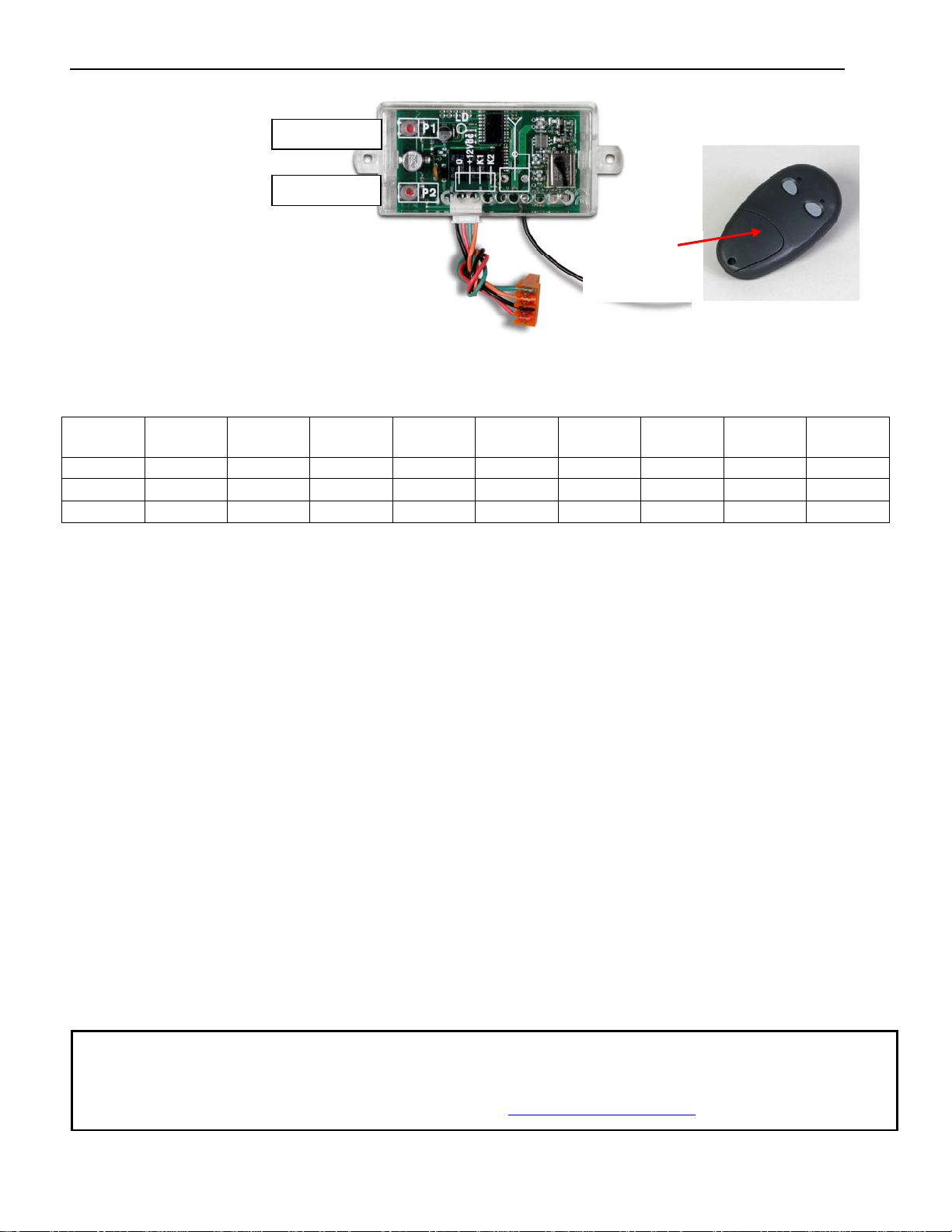
Programming Transmitter and LCR Receiver (model 433DSR2LC): Operating frequency 433.92 MHz.
Receiver can store up to 42 unique transmitter dipswitch code settings.
P1 Button
Receiver
P2 Button
Battery
Compartment
Door
Transmitter Setup: (It is recommended that the dipswitch code be changed from the default factory setting)
Open the battery compartment door and locate the dipswitches.
Change the dipswitches to the settings you prefer, record for future reference in the table below.
Switch
position
+
0
-
Switch 1 Switch 2 Switch 3 Switch 4 Switch 5 Switch 6 Switch 7 Switch 8 Switch
9
Transmitter Left Button to Receiver Programming: (standard Open/Stop/Close function)
1. Press and hold the left transmitter button down. Red light on transmitter should be on.
2. On the receiver, push the P1 push-button until the green LD light comes on.
3. Release both buttons. Transmitter left button to receiver programming is complete.
Transmitter Right Button to Receiver Programming: (Hold-Gate-Open) (Only if auto close timer is enabled)
1. The 2-channel receiver allows for programming the P2 relay from momentary mode (default) to latching mode.
Transmitter right button can be programmed to hold gate open, over-riding the auto-close feature if activated.
2. Press and hold the right transmitter button down. Red light on transmitter should be on.
3. Press the P2 push-button until the green LD light comes on.
4. Release both buttons. Transmitter right button to receiver programming is complete.
Receiver Programming: Relay P2 programming from momentary to latching mode (to hold gate open)
1. Press the P2 push-button until the green LD light comes on, then release. Green LD light should be steady.
2. While the green LD light is on, push the P1 push-button down and release. Green LD light should be flashing.
Latching mode is set.
Verifying Receiver P2 relay is programmed to latching mode:
1. Press the P2 push-button until the green LD light comes on, then release.
2. Green LD light should be flashing. If green LD light is steady, redo the Receiver Programming section above.
Resetting receiver P2 relay to momentary mode:
1. Press the P2 push-button until the green LD light comes on, then release. Green LD light should be flashing.
2. While the LD light is flashing, push the P1 push-button down and release. Green LD light should be steady.
Momentary mode is set.
The transmitters provided with your USAutomatic operator contain 2 buttons. Designate one
or all buttons for gate operation, if desired. The additional button may be programmed to
other devices such as a garage door if frequency is compatible. If frequency is not
compatible with existing product, please visit www.usautomatic.com
for other solutions.
Page 2
Erasing Single Transmitter from Receiver Memory:
The dipswitch settings of the transmitter to be deleted must be known. If known follow the steps below.
1. Set the dipswitches in a transmitter to match the switch settings of the transmitter code to delete.
2. Press and hold the left transmitter button.
3. On the receiver, push the P1 push-button until the green LD light comes on. Then release both.
4. Press and hold the right transmitter button.
5. On the receiver, push the P2 push-button until the green LD light comes on. Then release both.
6. Transmitter is now erased from receiver memory.
Erasing all Transmitters from Receiver Memory:
1. Press the P2 button on the receiver until the green LD light comes on. Then release P2 button.
2. While LD light is on press the P1 and P2 buttons simultaneously and hold until the green LD light begins to
blink slowly. It should blink 4 times then all transmitter codes are erased.
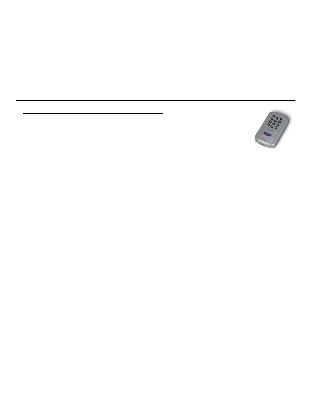
Programming Wireless Keypad (model 433 KPD) PUK code__________
Terms to understand:
¾ Master Password – The 5-digit code used to access programming features.
Factory default is “11111”. This should be changed for security reasons.
¾ Access Code – 2 to 5 digit codes used to operate the gate (24 unique codes are possible).
If access code is less than 5 digits it requires the # sign after code is entered.
Example: “2 #.” If code is 5 digits the # sign is not required.
¾ Relay 1 – The receiver has 2 relays. P1 (relay 1) is pre-wired to the “Push Button Input” on J2 connector.
¾ Relay 2 – The receiver has 2 relays. P2 (relay 2) is pre-wired to the “Open/Free Exit” on J2 connector.
¾ Keypad Security Code (Dip Switch Code) – This code makes your keypad unique to your installation. Keypad
does not have dip switches like the transmitter; instead it has virtual dip switches which can be programmed.
¾ PUK Code – “Password Unblocking Key.” The PUK code is located inside the keypad and is needed when the
master password has been lost. Record in space above for future reference. Must be 5 digits long.
¾ “ * ” Key – located on the keypad and used to cancel last command entered.
¾ Red Light Blinks – When blinking, the keypad is sending a signal to the receiver. Valid access code was entered.
Note: Do not install keypad until “Create Communication with Receiver P1 (relay 1)” has been completed.
Programming the Keypad for Operation
Create Access Code: (Code you use to operate the gate)
1. Enter the Master Password “11111”. (this is the factory default master password).
2. Enter “9” If correct, 2 short beeps (if 1 long beep is heard, start over with step 1).
3. Enter the new Access Code (up to 5 digits), if less than 5 digits, “#” is required.
4. Enter “9”
5. Enter the new Access Code again to verify.
6. Enter “1”. If this access code is for P1 (relay 1) Enter “2” if this access code is for P2 (relay 2).
7. If correct, 2 short beeps (if 1 long beep is heard, start over with step 1).
8. Continue below with “Create Communication with Receiver” to complete programming.
NOTE: Step 6 above allows you to select a unique frequency (1, 2, 3, 4) for the access code you are creating. Keypad can be
programmed with 4 different access codes each having a unique frequency. This is used when multiple gates are within range
of the keypad. Create an access code using 1 in step 6 for one gate. Create an access code using 2 in step 6 for the second gate.
This allows one keypad programmed with 2 access codes to operate 2 different gates within range or two keypads can be
installed on 2 different gates without inte rfering with each other. If 4 gates were involve d the n 3 a n d 4 could be used in step 6.
Also used to create a unique access code to activate the hold open featu re of fered with P2 (relay 2).
Create Communication with Receiver: *for P1 (relay 1) access code:
1. Carry keypad to receiver location for programming.
2. Enter Access Code for P1 (relay 1) on the keypad and continue to press the last key entered (red light blinks).
3. Press P1 (learn button) on the receiver until LD (green light) comes on and relay clicks.
Create Communication with Receiver: *for P2 (relay 2) access code:
1. Carry keypad to receiver location for programming.
2. Enter Access Code for P2 (relay 2) on the keypad and continue to press the last key entered (red light blinks).
3. Press P2 (learn button) on the receiver until LD (green light) comes on and relay clicks.
Page 3

Programming New Master Password: Once created record here for reference __________
1. Enter the Master Password “11111”.
2. Enter “8” If correct, 2 short beeps (if 1 long beep is heard, start over with step 1).
3. Enter the Master Password (up to 5 digits), if less than 5 digits, “#” is required.
4. Enter “8”
5. Enter the Master Password again to verify.
6. Press “8” If correct, 2 short beeps - New Master Password is set (If 1 long beep is heard, start over with step 1).
Programming Master Password Back to Factory Default: (11111)
1. Enter “11111”.
2. Press “8” (long beep).
3. Enter PUK code. (PUK must be 5 digits).
4. Press “8”.
5. Enter PUK code to confirm.
6. Press “8” (2 beeps) Master password reset complete.
Changing Keypad Security Code:
This keypad has a virtual dipswitch used to create your Security Code. The virtual dipswitch contains nine
3-position switches. To ensure neighboring keypads do not interfere with each other, the virtual switches should be
positioned in a random pattern, using the following procedure.
Example of random positioning of the virtual dipswitches to create a Security Code is shown below.
To enter the Security Code, enter the dipswitch number, followed by the dipswitch position character.
The Security Code would be entered as: 1# 20 3* 4* 5# 6* 7# 80 9*
Dipswitch
Position
#
0
*
Switch 1 Switch 2 Switch 3 Switch 4 Switch 5 Switch 6 Switch 7 Switch 8 Switch
9
X
X X
X X X X
X X
Use table below to create your random security code and follow steps below to program your keypad.
Dipswitch
Switch 1 Switch 2 Switch 3 Switch 4 Switch 5 Switch 6 Switch 7 Switch 8 Switch
Position
#
0
*
1. Enter the Master Password. This is not the code to operate the gate.
2. Enter “6” If correct, 2 short beeps (if 1 long beep is heard, start over with step 1).
3. Enter the Security Code created in the previous table. If correct, 2 short beeps after each switch number and
switch position combination is entered.
4. Enter “#”
5. Enter “6”
6. If correct, 2 short beeps (if 1 long beep is heard, start over with step 1).
Deleting Single Access Code:
1. Enter the Master Password.
2. Press the “7” key. If correct, 2 short beeps (if 1 long beep is heard, start over with step 1).
3. Enter the Access Code to be deleted.
4. Press the “7” key.
5. Reenter the Access Code to be deleted.
6. Press the “7” key. If correct, 2 short beeps (if 1 long beep is heard, start over with step 1).
Deleting All Access Codes:
1. Enter the Master Password.
2. Press the “7” key. If correct, 2 short beeps (if 1 long beep is heard, start over with step 1).
3. Reenter the Master Password.
4. Press the “7” key.
5. Reenter the Master Password.
6. Press the “7” key. If correct, 2 short beeps (if 1 long beep is heard, start over with step 1).
9
 Loading...