

Page 1

Platform Guide:
WANJet® 500
MAN-0230-01
Page 2

Page 3

Product Version
Publication Date
Legal Notices
This manual applies to the WANJet 500 hardware platform created by F5 Networks, Inc.
This guide was published on February 23, 2007.
Copyright
Copyright 2006-2007, F5 Networks, Inc. All rights reserved.
F5 Networks, Inc. (F5) believes the information it furnishes to be accurate and reliable. However, F5
assumes no responsibility for the use of this information, nor any infringement of patents or other rights of
third parties which may result from its use. No license is granted by implication or otherwise under any
patent, copyright, or other intellectual property right of F5 except as specifically described by applicable
user licenses. F5 reserves the right to change specifications at any time without notice.
Trademarks
F5, F5 Networks, the F5 logo, BIG-IP, 3-DNS, iControl, Internet Control Architecture, IP Application
Switch, iRules, OneConnect, Packet Velocity, SYN Check, Control Your World, ZoneRunner, uRoam,
FirePass, TrafficShield, Swan, WANJet, WebAccelerator, and TMOS are registered trademarks or
trademarks, and Ask F5 is a service mark, of F5 Networks, Inc. in the U.S. and certain other countries. All
other trademarks mentioned in this document are the property of their respective owners. F5 Networks'
trademarks may not be used in connection with any product or service except as permitted in writing by
F5.
Patents
This product protected by U.S. Patents 6,327,242 and 7,126,955. Other patents pending.
Export Regulation Notice
This product may include cryptographic software. Under the Export Administration Act, the United States
government may consider it a criminal offense to export this product from the United States.
RF Interference Warning
This is a Class A product. In a domestic environment this product may cause radio interference, in which
case the user may be required to take adequate measures.
FCC Compliance
This equipment has been tested and found to comply with the limits for a Class A digital device pursuant
to Part 15 of FCC rules. These limits are designed to provide reasonable protection against harmful
interference when the equipment is operated in a commercial environment. This unit generates, uses, and
can radiate radio frequency energy and, if not installed and used in accordance with the instruction manual,
may cause harmful interference to radio communications. Operation of this equipment in a residential area
is likely to cause harmful interference, in which case the user, at his own expense, will be required to take
whatever measures may be required to correct the interference.
Any modifications to this device, unless expressly approved by the manufacturer, can void the user's
authority to operate this equipment under part 15 of the FCC rules.
Canadian Regulatory Compliance
This Class A digital apparatus complies with Canadian ICES-003.
Platform Guide: WANJet® 500 i
Page 4

Standards Compliance
This product conforms to the IEC, European Union, ANSI/UL and Canadian CSA standards applicable to
Information Technology products at the time of manufacture.
VCCI Class A Compliance
This is a Class A product. In a domestic environment, this product may cause radio interference, in which
case the user may be required to take corrective actions. VCCI-A
ii
Page 5

Table of Contents
Page 6

Page 7

1
Introducing the WANJet 500 Platform
Overview of the WANJet 500 platform ....................................................................................1-1
Getting started with the WANJet 500 platform .....................................................................1-2
Components provided with the WANJet 500 ...............................................................1-2
Peripheral hardware that you provide ..............................................................................1-4
Familiarizing yourself with the WANJet 500 ............................................................................1-5
Using the WANJet 500 hardware ......................................................................................1-5
About this guide ..............................................................................................................................1-7
Finding additional information and technical support ...................................................1-8
Stylistic conventions ..............................................................................................................1-8
2
Installing the WANJet 500 Platform
Installing the hardware ...................................................................................................................2-1
Types of mounts ....................................................................................................................2-1
General recommendations for mounting a unit in a rack ............................................2-1
Installing the WANJet 500 hardware ................................................................................2-2
Powering up the WANJet 500 platform ....................................................................................2-5
Configuring the addresses .............................................................................................................2-6
Connecting the cables ....................................................................................................................2-9
Table of Contents
3
Using the WANJet 500 LCD and LEDs
Operating the LCD panel .............................................................................................................3-1
Configuring the WANJet 500 using the LCD .................................................................3-3
Administering the WANJet 500 using the LCD .............................................................3-3
Understanding LED behavior .......................................................................................................3-5
LED indicators ........................................................................................................................3-5
Network interface card LEDs .............................................................................................3-6
4
Maintaining the WANJet 500 Platform
Reviewing maintenance options ..................................................................................................4-1
Changing a power supply ..............................................................................................................4-1
Replacing the power supply .................................................................................................4-1
Replacing a hard drive ....................................................................................................................4-2
Removing and replacing a hard drive tray ........................................................................4-2
5
Understanding Environmental Guidelines for the WANJet 500 Platform
Environmental requirements ........................................................................................................5-1
General environmental guidelines ......................................................................................5-1
6
Reviewing Hardware Specifications
WANJet 500 platform specifications ..........................................................................................6-1
Platform Guide: WANJet® 500 v
Page 8

Table of Contents
A
Installing the WANJet Appliance Using the Rail-Mount Kit
Installing the rail-mount kit ..........................................................................................................A-1
Installing the kit hardware ..................................................................................................A-1
Installing the unit into a rail-mount rack .........................................................................A-5
Connecting cables and other hardware ..........................................................................A-5
B
Platform-Specific Hazardous Substance Levels, for China
WJ500, WA4500, and EM3000 platforms ................................................................................ B-1
Glossary
Index
vi
Page 9

1
Introducing the WANJet 500 Platform
• Overview of the WANJet 500 platform
• Getting started with the WANJet 500 platform
• Familiarizing yourself with the WANJet 500
• About this guide
Page 10

Page 11
Introducing the WANJet 500 Platform
Overview of the WANJet 500 platform
F5® Networks WANJet® 500 platform is an appliance that delivers
LAN-like application performance over the WAN. The WANJet 500
accelerates applications including file transfer, email, client-server
applications, data replication, and others, resulting in predictable, fast
performance for all WAN users.
The WANJet 500 platform features fault tolerance and scalability for over
20,000 optimized connections. You can incorporate the WANJet 500
seamlessly across all wide-area networks including dedicated links, IP
VPNs, frame relay, and satellite connections. The WANJet 500 platform is
Restriction of Hazardous Substances (RoHS) compliant, and meets RoHS
guidelines regarding lead-free electronic equipment.
For detailed hardware specifications on the WANJet 500, see WANJet 500
platform specifications, on page 6-1.
The WANJet 500 delivers excellent application performance and reduces IT
expenses. Operating at Layer 5 of the OSI reference model, the WANJet
500 has full application knowledge and network awareness. The WANJet
appliance integrates key performance technologies, including Transparent
Data Reduction™, adaptive TCP optimization, site-to-site encryption, and
quality of service, that are applied to application streams.
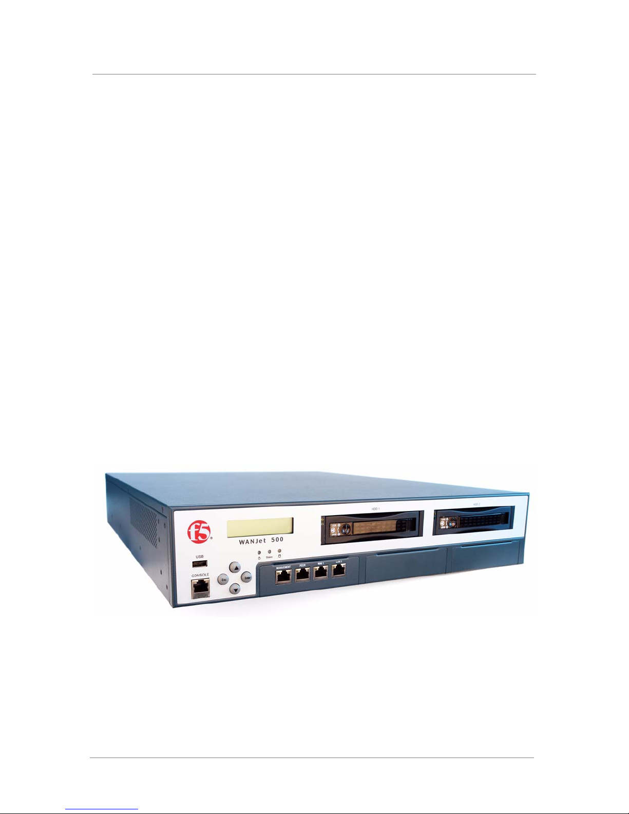
Figure 1.1 shows the WANJet 500 platform. For details on configuring and
maintaining the WANJet 500, see the WANJet
Guide.
Figure 1.1 Front view of the WANJet 500 platform
®
Appliance Administrator
Platform Guide: WANJet® 500 1 - 1
Page 12

Chapter 1
Getting started with the WANJet 500 platform
You must complete the following basic tasks to install and set up the
WANJet 500 platform.
• Acquaint yourself with the WANJet 500 hardware. For more
information, see Familiarizing yourself with the WANJet 500, on page
1-5.
• Review the hardware requirements. For more information about the
hardware requirements, read the following sections, Components
provided with the WANJet 500, following, and Peripheral hardware that
you provide, on page 1-4.
• Install the WANJet 500 hardware and connect it to the network, and
optionally connect the peripheral hardware. For more information on
mounting the hardware and attaching cables, see Installing the hardware,
on page 2-1.
• Understand the environmental guidelines. For more information, see
Chapter 5, Understanding Environmental Guidelines for the WANJet 500
Platform.
The WANJet 500 comes with the hardware that you need for installation.
However, you must also provide standard peripheral hardware, such as a
serial terminal, if you want to administer the WANJet 500 directly.
Components provided with the WANJet 500
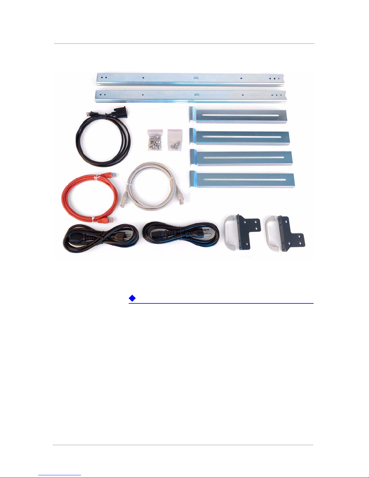
When you unpack the WANJet 500, you should make sure that the
following components, shown in Figure 1.2, are included:
• Rack-mount ears and handles
• Rail-mount kit
• Serial port console cable
• Two power cords
• Two CAT-5e cables (one gray straight-through and one red crossover
cable)
• Two packs of screws (rack-mount and rail-mount screws)
1 - 2
Page 13
Introducing the WANJet 500 Platform
Figure 1.2 Components included with the WANJet 500 platform
Important
The power cables included with this unit are for exclusive use with this unit
and should not be used with other electrical appliances. The unit handles
may look different from those shown in the figure.
Platform Guide: WANJet® 500 1 - 3
Page 14

Chapter 1
Peripheral hardware that you provide
For each WANJet 500 that you install, the peripheral hardware you provide
is determined by the configuration you want to create:
◆ If you want direct administrative access to the WANJet 500, you need
standard input/output hardware. This requires a serial console or a PC
with a serial connector. (You connect it to the WANJet 500 using the
serial port console cable that comes with the WANJet appliance.)
◆ You also need network hubs, switches, or concentrators to connect to the
WANJet 500 network interfaces. The devices you select must be
compatible with the network interface cards installed in the WANJet 500.
The devices must support 10/100 Ethernet or Gigabit Ethernet.
• Ethernet requires either a 10 Mbps or 100 Mbps hub or switch.
• Gigabit Ethernet requires a compatible Gigabit Ethernet switch.
◆ If you want to use the Management port, you must have an
administrative workstation on the same IP network as the WANJet 500.
◆ If you plan on doing remote administration from your own PC
workstation (instead of using the Management port), we recommend that
you have your workstation already in place on the corporate network.
1 - 4
Page 15
Introducing the WANJet 500 Platform
Familiarizing yourself with the WANJet 500
Before you begin to install the WANJet 500, quickly review the following
figures that identify the controls and ports on the front and the back of the
WANJet 500.
Using the WANJet 500 hardware
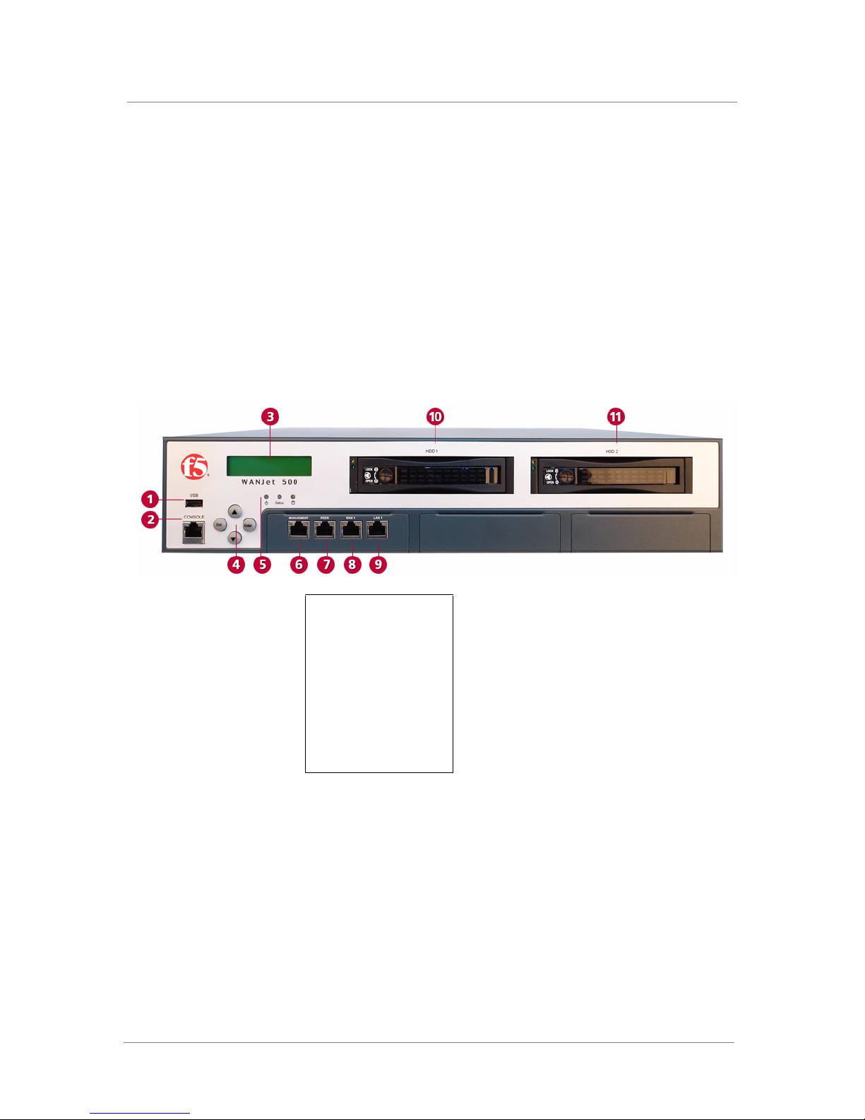
You need to be familiar with both the front and back panels of the WANJet
500. Figure 1.3 illustrates the front of a WANJet 500. On the front of the
unit, you can connect a console, connect a USB keyboard, and view the
indicator lights for hard disk access.
1. USB port
2. Console port
3. LCD display
4. LCD keypad
5. LED status indicators
6. Management port
7. Peer port
8. WAN 1 port
9. LAN 1 port
10. Hard drive 1
11.
Hard drive 2 (optional)
Figure 1.3 Front view of a WANJet 500 platform
If you have physical access to the unit, you can use the front-panel LEDs to
assess the condition of the unit. For details about the behavior of the LEDs,
see Understanding LED behavior, on page 3-5.
Platform Guide: WANJet® 500 1 - 5
Page 16
Chapter 1
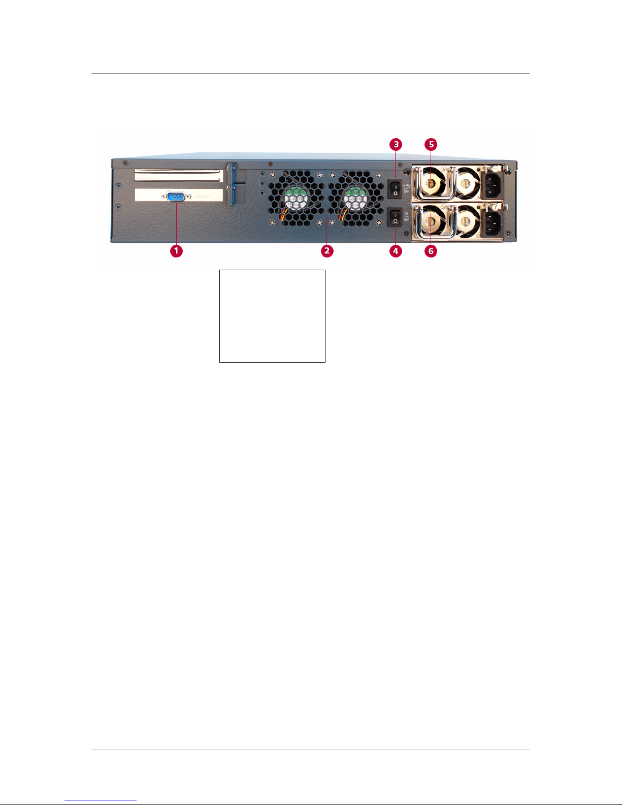
Figure 1.4 illustrates the back of a WANJet 500.
1. Failover port (not used)
2. Fans
3. Power supply alarm
mute switch
4. Power switch
5. Power supply 1
6. Power supply 2
Figure 1.4 Back view of the WANJet 500 platform
Note that the failover port, labeled 1 in the figure, is not used. You may use
the Peer port on the front to set up a redundant system for the WANJet
platform. Refer to the WANJet
on how to set up WANJet platforms in a redundant system.
®
Appliance Administrator Guide for details
1 - 6
Page 17

About this guide
Introducing the WANJet 500 Platform
This guide describes the features of the WANJet 500 platform and contains
the following information.
• Getting familiar with the WANJet platform
Learn about the parts of the WANJet platform. For more information, see
Familiarizing yourself with the WANJet 500, on page 1-5.
• Installing the platform
Learn how to install the hardware in a rack, power it up, perform
minimal configuration tasks, and connect the network cables. For more
information, see Chapter 2, Installing the WANJet 500 Platform.
• Using the LCD keypad
Learn about using the LCD to configure addresses, shut down and restart
the WANJet platform, and perform other basic tasks. For more
information, see Operating the LCD panel, on page 3-1.
• Understanding LED behavior
Learn how to decipher what conditions are signaled by the LEDs. For
more information, see Understanding LED behavior, on page 3-5.
• Changing a power supply
Learn how to replace a power supply. For more information, see
Changing a power supply, on page 4-1.
• Replacing the hard drives
Learn how to replace the hot-swappable drives that may be contained in
each of the drive bays. For more information, see Replacing a hard drive,
on page 4-2.
• Understanding the environmental guidelines
Learn about the environmental requirements for the WANJet 500
platform. For more information, see Chapter 5, Understanding
Environmental Guidelines for the WANJet 500 Platform.
• Reviewing the hardware specifications
Review the hardware specifications for the WANJet 500 platform. For
more information, see Chapter 6, Reviewing Hardware Specifications.
• Installing a rail-mount kit
Learn how to install a rail-mount kit into a rack so the installed
WANJet 500 can slide in and out of the rack. For more information, see
Appendix A, Installing the WANJet Appliance Using the Rail-Mount Kit.
Platform Guide: WANJet® 500 1 - 7
Page 18

Chapter 1
Finding additional information and technical support
In addition to this guide, there are other sources of documentation you can
use in order to work with the WANJet platform. The information is
available in the guides and documents described below. The following
documentation is included with the WANJet platform.
◆ WANJet 500 Appliance Quick Start Card
The WANJet hardware includes the printed WANJet 500 Appliance
Quick Start Card. This document provides basic instructions for a quick
setup and initial configuration of the WANJet platform.
In addition to the documentation included with the platform, you can find
comprehensive technical documentation using the following resources.
Stylistic conventions
◆ WANJet Appliance Administrator Guide
The WANJet
®
Appliance Administrator Guide provides all the
information the administrator needs to configure and manage the
WANJet appliance. It introduces the concepts of optimization,
Transparent Data Reduction (TDR), Application QoS, Type of Service,
and Connection Interception (CI).
◆ Release notes
Release notes for the WANJet appliance are available in HTML format
on the F5 Networks Technical Support web site, http://tech.f5.com. The
release notes contain the latest information for the current version,
including a list of new features and enhancements, a list of fixes, and a
list of known issues.
◆ Technical support through the World Wide Web
The F5 Networks Technical Support web site, http://tech.f5.com,
provides the latest release notes, technical notes, answers to frequently
asked questions, updates to the guides (if available), and the Ask F5
search engine.
To help you easily identify and understand important information, our
documentation uses the stylistic conventions described below.
SM
Using the solution examples
Identifying new terms
1 - 8
Examples in this documentation use only private class IP addresses. When
you set up the solutions we describe, you must use valid IP addresses
suitable to your own network in place of our sample addresses.
When we first define a new term, the term is shown in bold italic text. For
example, the Web UI is the browser-based utility for administering the
WANJet appliance.
Page 19

Introducing the WANJet 500 Platform
Identifying references to objects, names, and commands
We apply bold formatting to a variety of items to help you easily pick them
out of a block of text. These items include web addresses, IP addresses,
utility names, and portions of commands, such as variables and keywords.
For example, to discover devices requires that you include at least one
<ip_address> or an <ip_subnet> variable.
Identifying references to other documents
We use italic text to denote a reference to another document. In references
where we provide the name of a book as well as a specific chapter or section
in the book, we show the book name in bold, italic text, and the
chapter/section name in italic text to help quickly differentiate the two. For
example, you can find information about setting up optimization policies in
the Advanced Configuration chapter of the WANJet
Administrator Guide.
Identifying command syntax
®
Appliance
We show complete commands in bold Courier text. Note that we do not
include the corresponding screen prompt, unless the command is shown in a
figure that depicts an entire command line screen. For example, the
following command shows how to trace the route of IP packets from the
WANJet command line interface:
traceroute <ip_address>
Table 1.1 explains additional special conventions used in command line
syntax.
Item in text Description
\ Indicates that the command continues on the following line, and
< > Identifies a user-defined parameter. For example, if the command
| Separates parts of a command.
[ ] Indicates that syntax inside the brackets is optional.
... Indicates that you can type a series of items.
that users should type the entire command without typing a line
break.
has <your name>, type in your name, but do not include the angle
brackets.
Platform Guide: WANJet® 500 1 - 9
::= Means is defined as. Indicates that an argument is followed by the
description of the elements that you can use for the argument.
Table 1.1 Command line syntax conventions
Page 20

Chapter 1
1 - 10
Page 21

2
Installing the WANJet 500 Platform
• Installing the hardware
• Powering up the WANJet 500 platform
• Configuring the addresses
• Connecting the cables
Page 22

Page 23

Installing the hardware
After you have reviewed the hardware requirements and become familiar
with the WANJet 500, you can install the unit.
This chapter includes detailed instructions on installing and setting up the
WANJet platform. The same instructions appear in a briefer format in the
WANJet 500 Appliance Quick Start Card. If you have already followed the
instructions on the card, and have completed the installation successfully,
you may not need to read this chapter. It describes the same installation
procedure in more detail.
Types of mounts
Two types of mounts are available for the WANJet 500: the standard
front-rack mount that comes with the WANJet 500, and a rail mount that
allows you to slide the unit in and out as needed. The installation of the
WANJet 500 hardware differs depending on which type of mount you
decide to use.
Installing the WANJet 500 Platform
◆ Standard front mount
To install the WANJet 500 platform using the standard front-rack mount
that comes with the hardware, follow the instructions in To install the
unit into a standard-mount rack, on page 2-2.
◆ Optional rail mount
To install the WANJet 500 platform into a rail mount, first attach the
included rail-mount kit. Then, you can install the unit into the rack. For
details, refer to Appendix A, Installing the WANJet Appliance Using the
Rail-Mount Kit.
Whichever mount you are using, read the following general
recommendations before installing the WANJet 500.
General recommendations for mounting a unit in a rack
We recommend that all units have 1U of extra space between them when
mounted in a rack to allow for a rack mounting shelf, and to provide
additional air circulation for cooling the unit.
Although not required, the 1U of space between units makes it easier to
remove the unit from the rack in the event that the unit requires service. A
1U space between units also provides additional cable routing options.
Platform Guide: WANJet® 500 2 - 1
Page 24

Chapter 2
We recommend that you allow about 4 inches (100 mm) of space from the
front panel of the unit to the rack front or rack door. This provides enough
room to route the cables without bending them excessively.
WARNING
This product is sensitive to electrostatic discharge (ESD). We recommend
that when handling the unit, use proper ESD grounding procedures and
equipment.
Installing the WANJet 500 hardware
To use the standard front mount to hold the WANJet 500 unit, follow the
procedure in this section.
You may need a shelf or similar device to support the unit if a single person
is installing the unit. To prevent personal injury or damage to the unit, we
recommend having at least two people to perform the installation.
You can also install the unit onto any flat surface without having to install it
into a rack. In that case, continue on to Powering up the WANJet 500
platform, on page 2-5.
To install the unit into a standard-mount rack
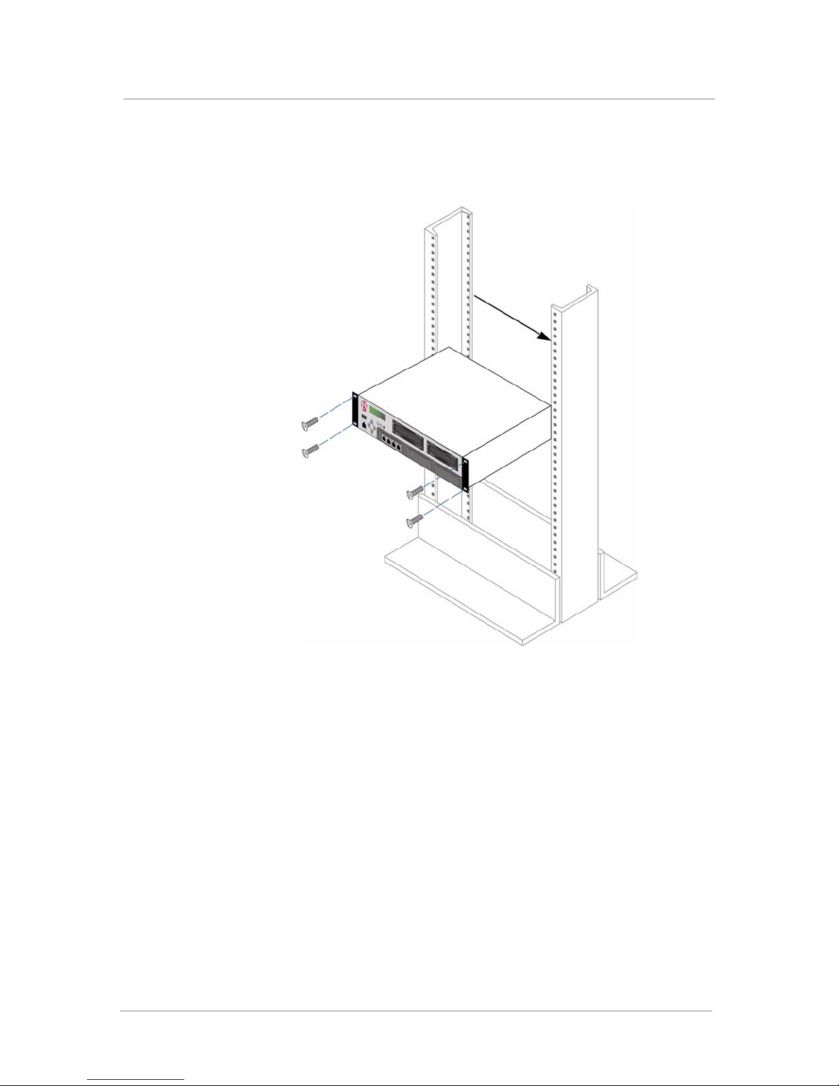
1. Attach the rack-mount ears to the unit, using four black screws per
ear.
2. If desired, attach the handles to the rack-mount ears using the
provided screws.
3. Lift the unit into place.
4. Secure the unit using the four rack-mounting screws that are
provided.
You need to tighten the screws to secure the unit to the rack to
provide adequate stability and to prevent the unit from falling out of
the rack. Securing the unit to the rack with the screws also provides
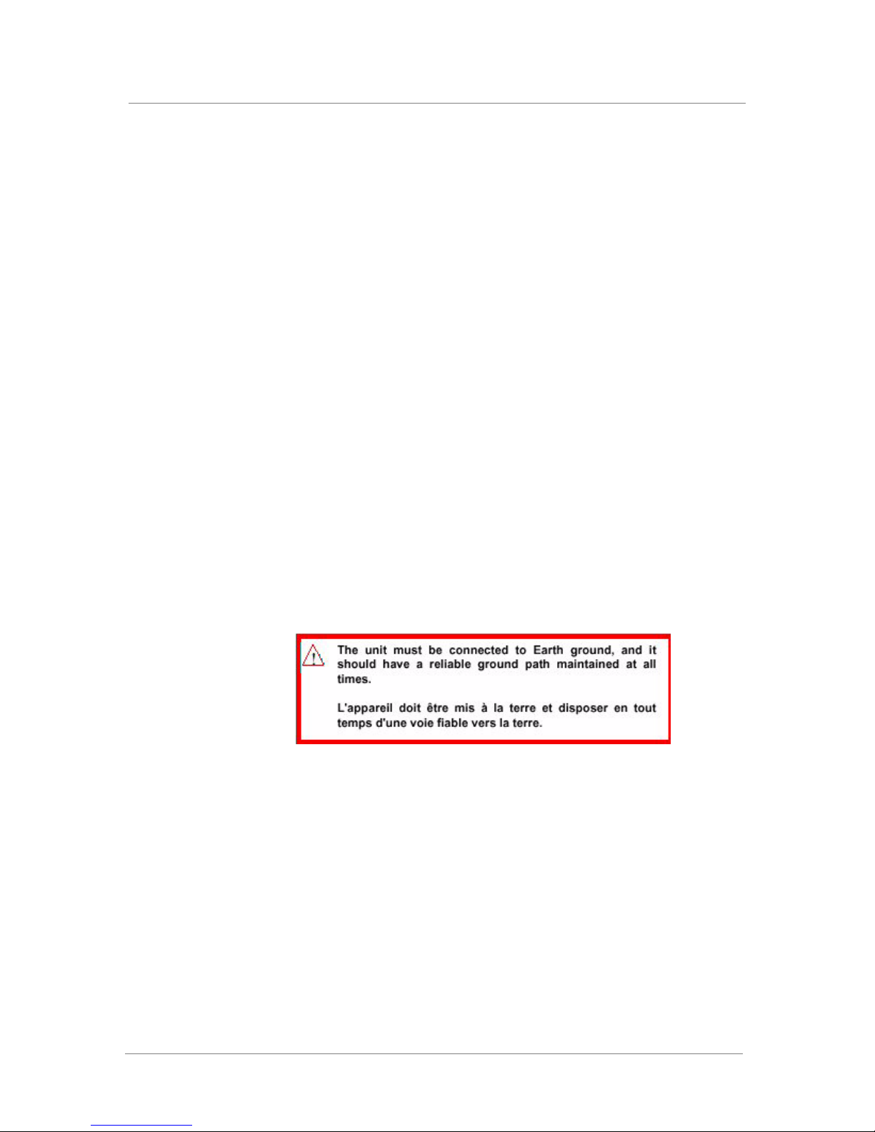
adequate grounding.
If the rack does not provide adequate support for the unit, you may need a
shelf kit. We recommend that you use the shelf kit created by the rack
manufacturer. (Some rack manufacturers provide shelf kits for their racks.)
2 - 2
Page 25
Installing the WANJet 500 Platform
Figure 2.1 shows the orientation of the WANJet 500 and the mounting
screws for installation into a standard 19" rack.
Figure 2.1 Platform orientation for rack mounting
Platform Guide: WANJet® 500 2 - 3
Page 26
Chapter 2
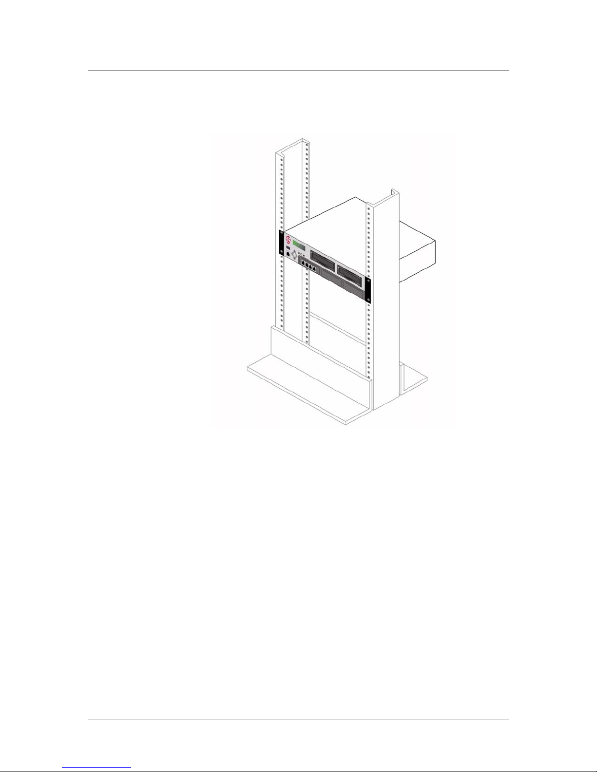
Figure 2.2 shows the WANJet 500 after it has been installed in the rack.
Figure 2.2 Platform installed in a 19" rack
Regardless of which mount type you use, complete the installation in this
order:
• Power on the unit
• Configure the addresses on the WANJet platform
• Connect the cables and other hardware
We recommend that you configure the addresses before connecting the
platform to the network.
2 - 4
Page 27

Installing the WANJet 500 Platform
Powering up the WANJet 500 platform
After you have installed the WANJet 500 platform, you can power it up.
Two power cords provide a redundant power supply.
To power up the WANJet platform
1. Insert the two power cords into the two power supplies (numbers 5
and 6 in Figure 1.4, on page 1-6) on the back of the WANJet
platform.
2. Plug each power cord into a separate power outlet (preferably to
different power circuits).
3. Press the power switch on the back of the unit (number 4 in
Figure 1.4, on page 1-6).
The unit starts up, and you may hear a warning sound.
If one of the power cords is not connected, or fails, the unit continuously
sounds a warning beep. To disable this sound, press the power supply alarm
mute switch (number 3 in Figure 1.4, on page 1-6).
When the appliance is running, the LCD displays the default IP address of
192.168.168.100. Wait approximately 10 more seconds for the operating
system to finish loading.
Platform Guide: WANJet® 500 2 - 5
Page 28

Chapter 2
Configuring the addresses
After the WANJet platform is powered on and started up, you need to do
some minimal configuration, such as entering the WANJet appliance IP
address, its subnet mask, and default gateway. You can configure the
addresses in one of two ways:
• Set the addresses using the four-key LCD keypad.
• Set the addresses using the config command from a serial console or PC.
The advantage of using the LCD keypad is that you do not have to connect
another computer to the platform. When you finish the initial configuration
on the LCD, you can log in to the Web UI from your computer as you
normally would to manage the device.
The advantage of using a serial console or PC is that the configuration is
easier from the command line than it is using arrow keys on the LCD
keypad. Connecting the console or PC is easy, and a few additional
commands are available from the command line.
It is up to you which method you prefer. The following procedures describe
both methods. The procedure on using the LCD describes minimal
configuration only. For details on the using the LCD, see Operating the
LCD panel, on page 3-1. If you want to use the config command, skip to To
set the addresses using a serial console or PC, on page 2-7.
To set the addresses using the LCD keypad
1. Locate the LCD display on the front of the WANJet 500 platform. It
should show the default IP address.
2. On the LCD keypad, press X.
The LCD displays Menu, followed by >Admin.
3. Press X.
The LCD displays Admin, followed by >Configure.
4. Press X.
The LCD displays Configure, followed by >IP Address.
5. Set the WANJet 500 IP address:
a) Press X to display the IP address (default: 192.168.168.100).
b) Press X to move from digit to digit in the address, and use S and
T to set the numbers in the address.
c) With the cursor on the last number on the right, press X.
The LCD displays Configure, followed by >IP Address.
2 - 6
Page 29

Installing the WANJet 500 Platform
6. Set the netmask:
a) Press T.
The LCD displays: >NetMask.
b) Press X to display the netmask (default: 255.255.255.000) and
set it as you did the IP address.
c) With the cursor on the last number on the right, press X.
The LCD again displays >Netmask.
7. Set the default gateway:
a) Press T.
The LCD displays >Gateway.
b) Press X to display the gateway address (default:
192.168.168.001) and set it as you did the other addresses.
c) With the cursor on the last number on the right, press X.
The LCD again displays >Gateway.
8. Use the defaults for the other values. If using a separate subnet for
management, you can optionally set the Mgt IP Address, Mgt
Netmask, and Mgt Gateway. See the WANJet
®
Appliance
Administrator Guide if you need additional details.
9. Save the values you set:
a) Press Tuntil you see >Apply.
b) Press X.
The LCD displays >Apply Now?
c) Press X to apply the values.
The LCD displays Config Applying, then Config Applied when
complete. The LCD panel shows the IP address you configured
for the WANJet platform.
Continue with the section called, Connecting the cables, on page 2-9.
To set the addresses using a serial console or PC
1. Connect the PC or serial terminal to the WANJet platform using the
RJ-45 to DB-9 serial port console cable supplied by F5 Networks.
a) Connect the DB-9 end to the PC or serial console.
b) Plug the RJ-45 end into the Console port (number 2 in Figure 1.3,
on page 1-5).
2. Display a console window. On a PC, you can use HyperTerminal or
an equivalent console emulator (set it to 9600 bits per second and
Xon/Xoff for flow control).
Platform Guide: WANJet® 500 2 - 7
3. When the appliance has finished booting, you should see the
WANJet appliance login prompt. (If you do not see the login
prompt, press Enter.)
Page 30

Chapter 2
4. Log in as admin with the default password of admin.
A message displays a list of commands that you can use from the
command line.
5. To start configuring the addresses, type config.
6. At the Set WANJet IP prompt, type the IP address of the WANJet
appliance (default is 192.168.168.100).
7. At the Set WANJet NetMask prompt, type the netmask you want
to assign to the WANJet appliance (default is 255.255.255.0).
8. At the Set WANJet Gateway prompt, type the IP address of the
WANJet appliance gateway (default is 192.168.168.001).
The media types are displayed.
Type 0 for Auto Sense
Type 100F for 100BaseTX Full-Duplex
Type 100H for 100BaseTX Half-Duplex
Type 10F for 10BaseT Full-Duplex
Type 10H for 10BaseT Half-Duplex
9. To set the media type, type the appropriate alphanumeric code that
represents the desired speed and duplex setting for the eth0 (LAN)
and eth1 (WAN) media types. You can use the default value of
Auto Sense unless you are familiar with the settings required in
your network environment and want to change them.
10. To manage the WANJet platform from a separate management
subnet, you can optionally set the IP addresses for the WANJet
Management IP, WANJet Management NetMask, and WANJet
Management Gateway. (These options are blank, by default.)
11. Determine how you want to allow access to the Web UI.
• To allow access from one IP address, at Set the IP of the first
machine allowed to access WANJet UI, type the IP address of
the only computer that you want to access the Web UI.
• To allow access from multiple IP addresses, leave this blank (the
default). In the navigation pane, expand Security and click IP
Access Control. See Granting Web UI access in the WANJet
Appliance Administrator Guide.
• To allow access from any browser on any computer in your
network (using the correct user name and password), leave this
field blank (the default).
12. Type exit to disconnect the session.
Within a few seconds, the LCD panel displays the IP address you
configured for the WANJet appliance.
Continue with the section called, Connecting the cables, on page 2-9.
®
2 - 8
Page 31

Connecting the cables
After you have configured the WANJet addresses, you can connect the
network cables. Note that you need to follow this procedure regardless of
the type of mount you installed (front mount or rail mount).
To connect the cables
1. Connect the gray Ethernet CAT-5e cable to the LAN1 port on the
front of the WANJet platform. Connect the other end to your LAN
switch.
2. Connect the red crossover CAT-5e cable to the WAN1 port on the
front. Connect the other end to your WAN router.
3. Optionally, connect an Ethernet cable to the Management port on
the front of the WANJet platform. Connect the other end to your
management network for out-of-band management.
You can now log on to the WANJet appliance remotely by using the
Web UI, and begin activating the license. For details about how to log on
and activate the license, refer to the WANJet
Guide.
Installing the WANJet 500 Platform
®
Appliance Administrator
Platform Guide: WANJet® 500 2 - 9
Page 32

Chapter 2
2 - 10
Page 33

3
Using the WANJet 500 LCD and LEDs
• Operating the LCD panel
• Understanding LED behavior
Page 34

Page 35

Operating the LCD panel
The liquid crystal display, or LCD panel, lets you control the WANJet 500
without attaching a serial or network cable. The LCD panel provides menus
with options to configure certain features on the system. The following
options are available on the LCD panel under the Admin menu:
• Configure
• Utils
•Restart
• Shutdown
•Exit
Some of the configuration options found on the LCD are also available
through the Web UI, the browser-based interface to the WANJet appliance.
Refer to the WANJet
the Web UI.
Table 3.1 summarizes the LCD options and their default values.
Using the WANJet 500 LCD and LEDs
®
Appliance Administrator Guide for details on using
LCD menu Options Default value Description
Configure IP Address 192.168.168.100 Sets the IP address for the WANJet appliance on the
NetMask 255.255.255.000 Sets the netmask for the WANJet appliance on the
Gateway 192.168.168.001 Specifies the IP address of the gateway. Also set on the
LAN speed and duplex
Auto Sense
1000 Full
100 Full
100 Half
10 Full
10 Half
WAN speed and duplex
Auto Sense
1000 Full
100 Full
100 Half
10 Full
10 Half
Auto Sense Sets the speed (in Mbps) and duplex mode (full or half)
Auto Sense Sets the speed (in Mbps) and duplex mode (full or half)
network. Also set on the Local WANJet screen in the
Configuration settings of the Web UI.
network. Also set on the Local WANJet screen in the
Configuration settings of the Web UI.
Local WANJet screen in the Configuration settings of
the Web UI.
for the network card connecting to the LAN. If you use
the Auto Sense setting, the WANJet appliance attempts
to match the characteristics of the network device it
connects to from the LAN port (for example, the LAN
router).
Also set on the Interfaces screen in the Configuration
settings of the Web UI.
for the network card connecting to the WAN. If you use
the Auto Sense setting, the WANJet appliance attempts
to match the characteristics of the network device it
connects to from the WAN port (for example, the WAN
router).
Also set on the Interfaces screen in the Configuration
settings of the Web UI.
Table 3.1 WANJet 500 LCD menus and options
Platform Guide: WANJet® 500 3 - 1
Page 36

Chapter 3
LCD menu Options Default value Description
Configure
(continued)
Mgt IP Address No IP address
specified
Mgt Netmask No IP address
specified
Mgt Gateway No IP address
specified
Allowed IP No IP address
specified
Apply Not applicable Saves the configuration changes made during this
Reset Not applicable Discards the configuration changes made during this
Sets the management IP address if managing the
WANJet platform on the management network
(optional).
Also set on the Local WANJet screen in the
Configuration settings of the Web UI.
Sets the netmask if managing the WANJet appliance on
the management network (optional).
Also set on the Local WANJet screen in the
Configuration settings of the Web UI.
Sets the gateway IP address if managing the WANJet
appliance on the management network (optional).
Also set on the Local WANJet screen in the
Configuration settings of the Web UI.
Specifies the IP address of the only computer that you
can use to log in to the WANJet Web UI. If you leave
this option empty, any computer on your network can
access the Web UI (using the correct user name and
password).
To allow or deny more than one IP address, use the IP
Access Control option on the Security screen in the
Web UI.
session.
session.
Utils Ping <IP address> None Tests whether an IP address is reachable across a
network.
Active
Operational mode
On/Off
Send snapshot Not applicable Sends a current snapshot of the system to the email
Restart Restart Now? Not applicable Reboots the WANJet platform. Also available on the
Shutdown Shutdown Now? Not applicable Shuts down the WANJet platform and turns off the
Exit Exit Now? Not applicable Ends the session and returns to the initial menu.
On (check box is
selected)
Turns WANJet appliance optimization on or off. Also set
on the Operational Mode screen in the Optimization
settings of the Web UI.
address configured on the Email Alert screen in the
Configuration settings of the Web UI. The snapshot is a
text file containing statistics, configuration information,
logs, and other useful information. Also available in the
Web UI.
Shutdown & Restart screen in the System settings of
the Web UI.
power. Also available on the Shutdown & Restart
screen in the System settings of the Web UI.
Table 3.1 WANJet 500 LCD menus and options (Continued)
3 - 2
Page 37

Using the WANJet 500 LCD and LEDs
Configuring the WANJet 500 using the LCD
You can use the Configure menu on the LCD to perform initial
configuration of the WANJet 500 platform. Initial configuration includes
setting the WANJet 500 IP address, netmask, gateway. For information on
initial setup, see Chapter 2, Installing the WANJet 500 Platform.
Administering the WANJet 500 using the LCD
You can perform several basic administration tasks from the LCD keypad
after the WANJet 500 is up and running.
Note
You should do most of the administration of the appliance using the Web UI
as described in the WANJet
®
Appliance Administrator Guide.
To ping another device on the network
1. On the LCD keypad, press X twice.
The LCD displays Menu, followed by >Configure.
2. Press T once to go to Utils, and then press X twice.
The LCD displays Ping, followed by an IP address with the cursor
on the first number.
3. Set the IP address to ping:
a) Press X to move from digit to digit in the address, and use S and
T to set the numbers in the address.
b) With the cursor on the last number on the right, press X.
The LCD displays Pinging, followed by the IP address you
specified. The LCD shows whether the ping was successful.
To set the operational mode to active or inactive
1. On the LCD keypad, press X twice.
The LCD displays Menu, followed by >Configure.
2. Press T once to go to Utils, press X once, and then press T once.
The LCD displays Active, followed by a small check box. A check
in the box means the WANJet appliance is active, and no check
means inactive, and traffic is not being optimized.
Platform Guide: WANJet® 500 3 - 3
3. Press X once to change the operational mode from On (Active) to
Off (Inactive).
Page 38

Chapter 3
To send a snapshot of the WANJet appliance to an email
address
Before you can use the LCD to take a snapshot of the WANJet appliance,
you must set up an email address on the Email Alert screen in the
Configuration settings of the Web UI. Refer to the section, Email Alerts, in
®
the WANJet
Appliance Administrator Guide.
1. On the LCD keypad, press X twice.
The LCD displays Menu, followed by >Configure.
2. Press T once to go to Utils, press X once, and then press T twice
to display Send Snapshot.
3. Press X once to take a snapshot of the state of the WANJet
appliance, and mail it to the email address specified in the Web UI.
To restart the WANJet appliance
1. On the LCD keypad, press X twice.
The LCD displays Menu, followed by >Configure.
2. Press T twice to go to Restart.
3. Press X once.
The LCD displays Restart Now?
4. Press X once to restart the WANJet appliance.
To shut down the WANJet appliance
1. On the LCD keypad, press X twice.
The LCD displays Menu, followed by >Configure.
2. Press T three times to go to Shutdown.
3. Press X once.
The LCD displays Shutdown Now?
4. Press X once to shutdown the WANJet appliance.
The system shuts down, and then power turns off.
3 - 4
Page 39
Understanding LED behavior
This section describes the behavior of the LED indicators and the network
interface card LEDs on the WANJet 500 platform.
LED indicators
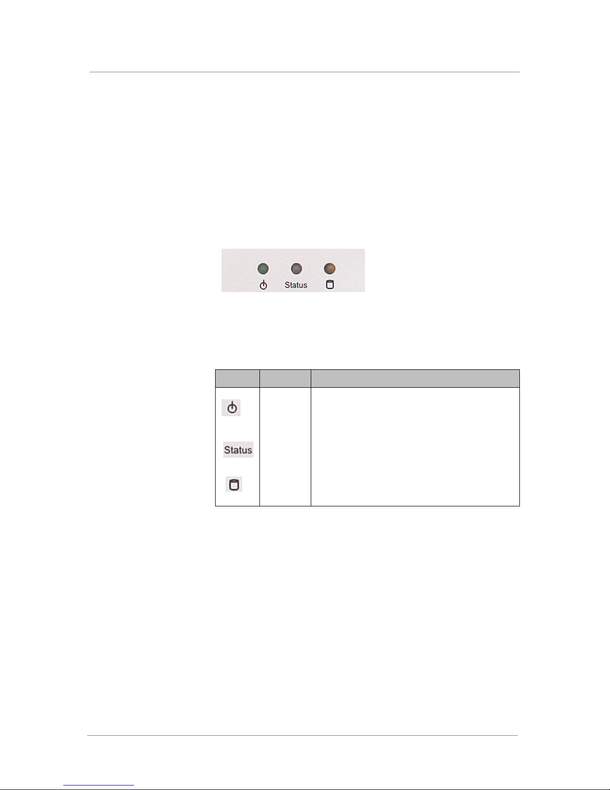
There are three LED indicators on the faceplate of each unit, as shown in
Figure 3.1.
Figure 3.1 LED indicators
Using the WANJet 500 LCD and LEDs
Each LED indicator serves a specific function, as defined in Table 3.2.
Label Function Description
Power Reports the power status: on (green) or off (none). Off
indicates that the unit is not turned on, or that there is
no power connected to the unit.
System
status
Hard disk
drives
Reports the state of the system: on (green) or off
(none).
Reports the status of the hard drives: blinking (yellow)
when data is accessed, or off (none) when the drives
are idle.
Table 3.2 LED indicator functions
Platform Guide: WANJet® 500 3 - 5
Page 40
Chapter 3
Network interface card LEDs
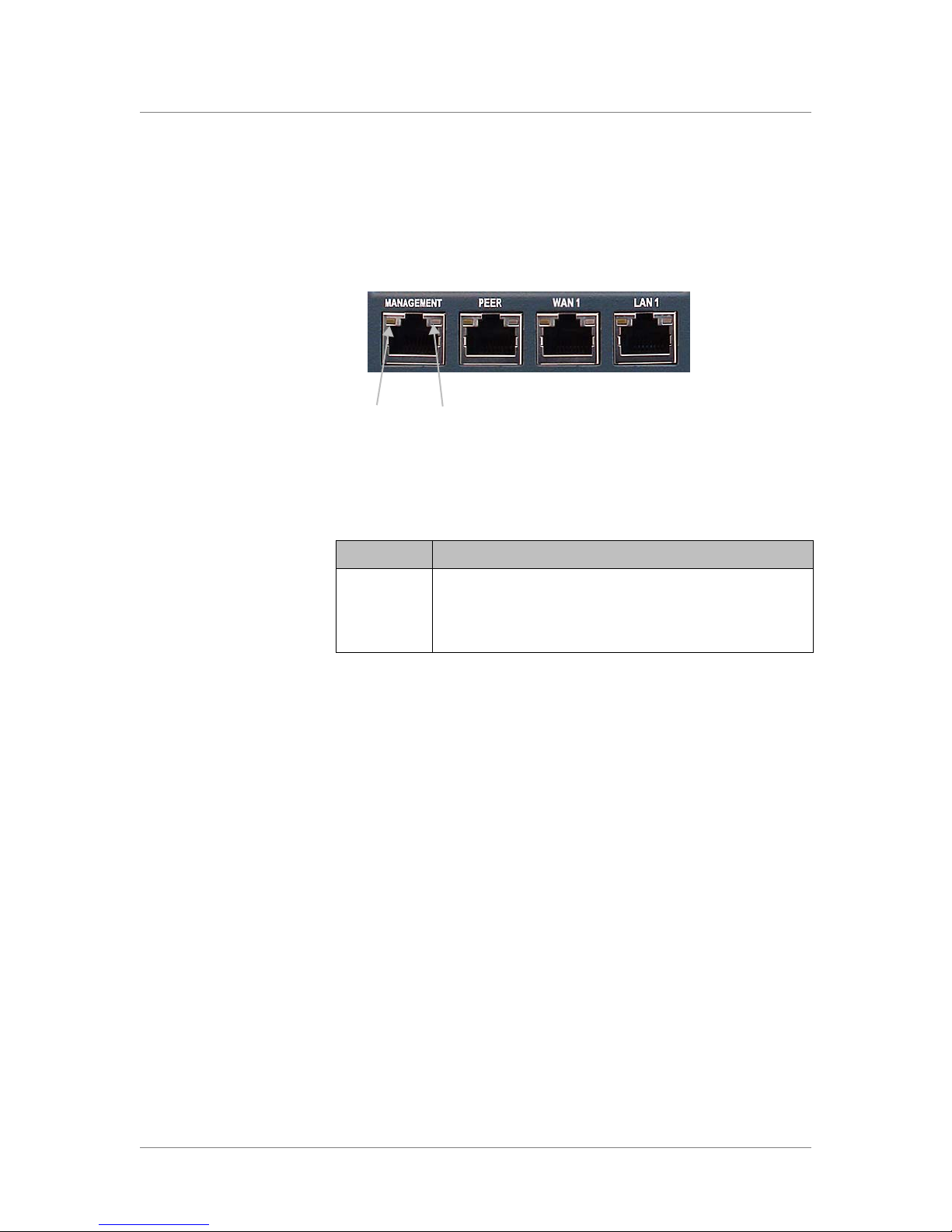
The WANJet 500 has four network interface card (NIC) ports, each of
which have two LEDs. Figure 3.2 shows the ports and shows where the
LEDs are located on the Management port.
Link activity Speed
Figure 3.2 Network interface card LEDs
Table 3.3 provides a description of the LEDs on the NICs.
LED Description
Link activity Displays the status of the link: active (green) or off (none).
Speed Indicates the speed of the connection: Gigabit (amber),
100BaseT (green), or 10BaseT (off).
Table 3.3 LEDs on WANJet 500 NIC ports
3 - 6
Page 41

4
Maintaining the WANJet 500 Platform
• Reviewing maintenance options
• Changing a power supply
• Replacing a hard drive
Page 42

Page 43

Reviewing maintenance options
The WANJet 500 platform contains several field replaceable units (FRUs).
The FRUs provide the ability to replace parts of the system without
replacing the complete system. The FRUs currently available for this
platform are:
• Power supply replacement
• Hard drive replacement
Changing a power supply
The WANJet 500 platform has two hot swappable redundant power
supplies. You can replace the power supply in the event of a power supply
failure.
Maintaining the WANJet 500 Platform
Replacing the power supply
You do not need special tools to replace a power supply. Because the power
supply is a redundant, hot swappable power supply, you can replace it while
the system is running.
To replace a power supply
1. On the back panel of the device, locate the power supply that you
want to replace.
2. Remove the power cable from the power supply that you want to
replace.
A power supply alarm sounds, indicating that a power supply was
removed or is not receiving power.
3. To silence the alarm, press the alarm mute switch (number 3 in
Figure 1.4, on page 1-6) that is located to the left of the power
supply array.
4. Each power supply is secured to the chassis by a self-clinching
knurled fastener and release lever. Loosen the knurled fastener by
turning it counterclockwise.
5. Move the release lever to the left and pull the power supply out of
the system.
6. Slide the new power supply into the power supply slot.
The power supply is connected to the system when you slide it
completely into the chassis.
Platform Guide: WANJet® 500 4 - 1
7. Tighten the knurled fastener into place by turning it clockwise.
8. Re-attach the power cable.
Page 44
Chapter 4
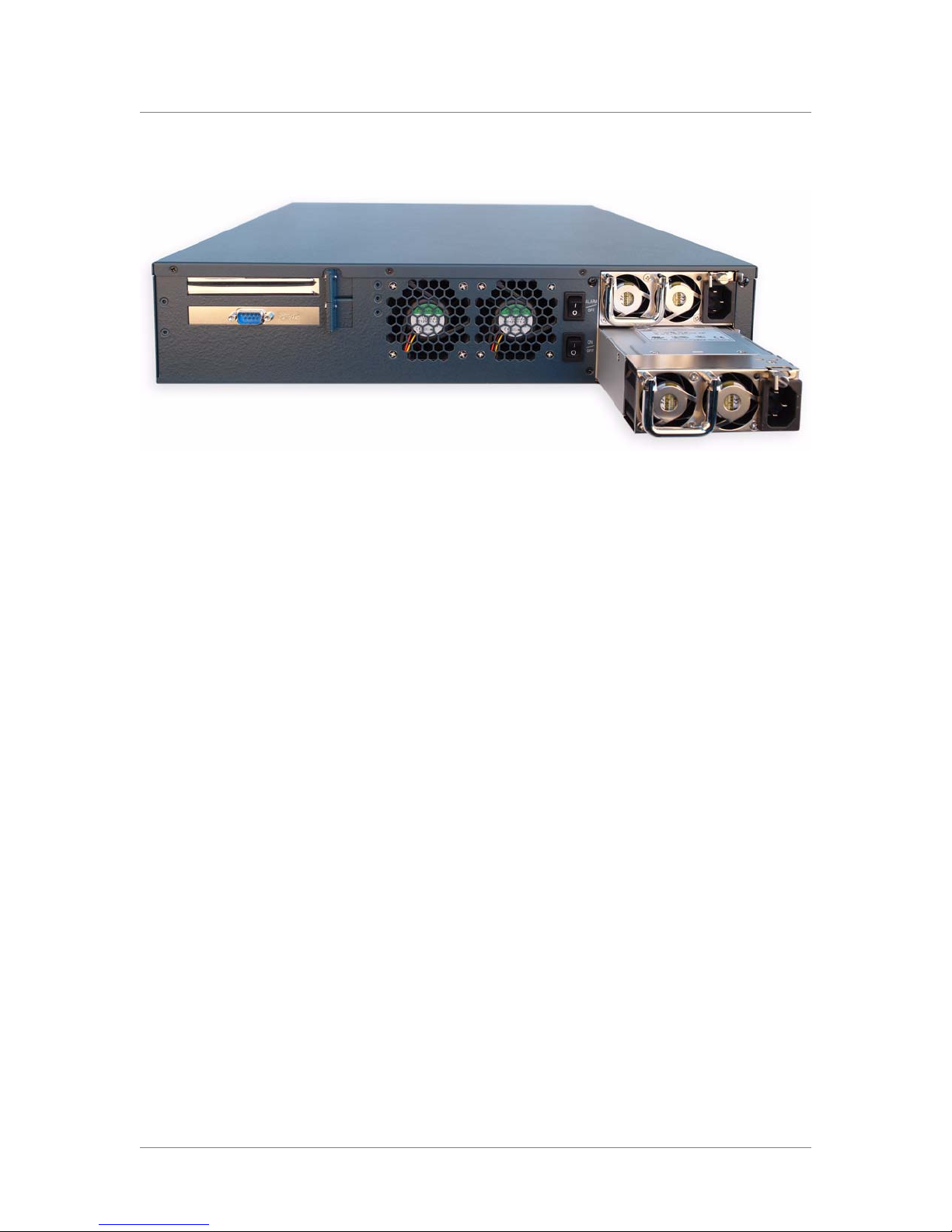
Figure 4.1 Power supply partially removed from the system
Figure 4.1 shows a picture of the unit with the power supply partially
removed from the WANJet 500 platform.
Replacing a hard drive
The WANJet 500 platform includes one hot swappable hard drive and has a
slot for an optional second hot swappable hard drive. You can change or
replace a hard drive tray as part of the routine maintenance of the unit, or in
the event of a drive failure.
Removing and replacing a hard drive tray
You do not need special tools to replace a hard drive tray.
To remove a hard drive
1. Each hard drive tray is secured by a simple switch. To unlock the
switch, turn the switch counterclockwise from Lock to Open.
2. Push the Lock/Open switch slightly to the left to release the tray
lever.
The tray lever extends from the drive tray.
4 - 2
3. Grip the tray lever and pull the drive tray out of the system.
Page 45
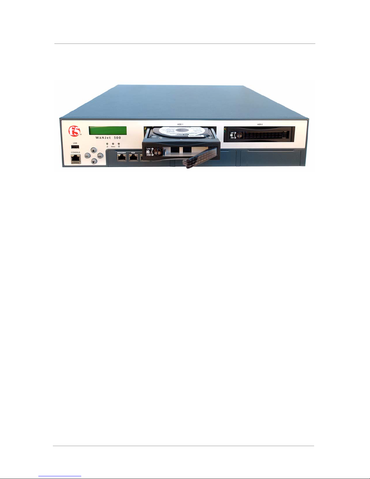
Figure 4.2 Removable drive tray and hard drive
Maintaining the WANJet 500 Platform
Figure 4.2 shows a picture of the drive tray assembly partially removed from
the WANJet appliance.
To replace a hard drive
After you remove a hard drive using the procedure To remove a hard drive,
on page 4-2, you can replace a hard drive using the following procedure.
1. Slide the new tray and hard drive into the chassis.
2. After the drive and tray are secured in the chassis, turn the dial on
the front of the drive clockwise to Lock to secure the tray lever.
Platform Guide: WANJet® 500 4 - 3
Page 46

Chapter 4
4 - 4
Page 47

5
Understanding Environmental Guidelines for
the WANJet 500 Platform
• Environmental requirements
Page 48

Page 49
Understanding Environmental Guidelines for the WANJet 500 Platform
Environmental requirements
Before you install the WANJet 500 platform, review the following
guidelines to make sure that you are installing and using the appliance in the
appropriate environment.
General environmental guidelines
A WANJet 500 platform is an industrial network appliance, designed to be
mounted in a standard 19-inch rack. To ensure safe installation and
operation of the unit, adhere to these recommendations:
• Install the rack according to the manufacturer’s instructions, and check
the rack for stability before placing equipment in it.
• Build and position the rack so that after you install the WANJet 500, the
power supply and the vents on both the front and back of the unit remain
unobstructed. The WANJet 500 must have adequate ventilation around
the unit at all times.
• Do not allow the air temperature in the room to exceed 40° C.
• Do not plug the unit into a branch circuit shared by more electronic
equipment than the circuit is designed to manage safely at one time.
• This product is sensitive to electrostatic discharge (ESD). We
recommend that when you install or maintain the unit, you use proper
ESD grounding procedures and equipment.
Platform Guide: WANJet® 500 5 - 1
Page 50
Chapter 5
5 - 2
Page 51

6
Reviewing Hardware Specifications
• WANJet 500 platform specifications
Page 52

Page 53

WANJet 500 platform specifications
The following specifications apply to the WANJet 500 platform.
Item Specification
Dimensions 550mmH x 431mmW x 88mmD
(3.5"H x 17"W x 22"D) per unit
2U industry standard rack-mount chassis
Weight 14.0 kilograms (30.87 lbs.) per unit
Processor
Power Supply 2 x 460W redundant hot swappable power supplies
Input Voltage 90–264 VAC, +/-10%
Maximum Power
Consumption
Maximum Heat Output 1570 BTUs
Network Interfaces 4 Gigabit Ethernet ports
Hard Drive Capacity 250 GB dual 3.5" hot swappable SATA hard drives
LCD module LCD display and 4-button keypad
RAM 4 GB DDR
Operating
Temperature
Non-operating
ambient temperature
range
Relative Humidity 5% to 95% at 40° C (104° F)
Hazardous Substance
Compliance
Safety Agency
Approval
Electromagnetic
Emissions
Certifications
®
Intel
Xeon Processor 3.2 GHz
460 W
(one included; second optional drive available)
0° to 40° C (32° to 104° F)
Temperature -40° to 70° C (-40° to 158° F) at a relative
humidity of 5% to 95%
RoHS compliant
UL/CUL/CE
EMC: FCC Class B
FCC Part 15 Class A
EN 55022 Class A
EN 55024
EN 61000-3-2
EN 61000-3-3
VCCI Class A
Reviewing Hardware Specifications
Platform Guide: WANJet® 500 6 - 1
Table 6.1 WANJet 500 platform specifications
Important
Specifications are subject to change without notification.
Page 54

Chapter 6
6 - 2
Page 55

A
Installing the WANJet Appliance Using the
Rail-Mount Kit
• Installing the rail-mount kit
Page 56

Page 57

Installing the WANJet Appliance Using the Rail-Mount Kit
Installing the rail-mount kit
The WANJet 500 platform includes two types of mounting devices:
• Rack-mount ears
• Rail-mount kit
The rack-mount ears are suitable for a standard type of mount. With
rack-mount ears, you can bolt the unit directly into the rack.
As an option, you can use an alternative type of mount, called a rail mount,
which allows you to slide the unit in and out of the rack. To install this
rail-mount kit and install the unit into the rack, you need to perform the
following tasks:
• Install the rail-mount kit hardware.
• Install the unit into the rack.
• Connect cables and other hardware.
To perform these tasks, follow the instructions in this appendix.
WARNING
The rail-mount installation procedure requires two people to lift and install
the equipment.
Installing the kit hardware
Installing the rail-mount kit involves attaching rail units to the system and
attaching rails to the server rack. The rail-mount kit consists of the following
parts:
• Two inner rails that attach to either side of the unit
After you attach the rails to the WANJet appliance, these inner rails slide
into the outer rails that you install onto the rack.
• Four mounting brackets that attach to the rack
The mounting brackets attach to each post on the rack. The outer rails
attach to the brackets.
• Two outer rails that attach to the mounting brackets on the rack
The inner rails that you install on the sides of the unit slide into these
outer rails.
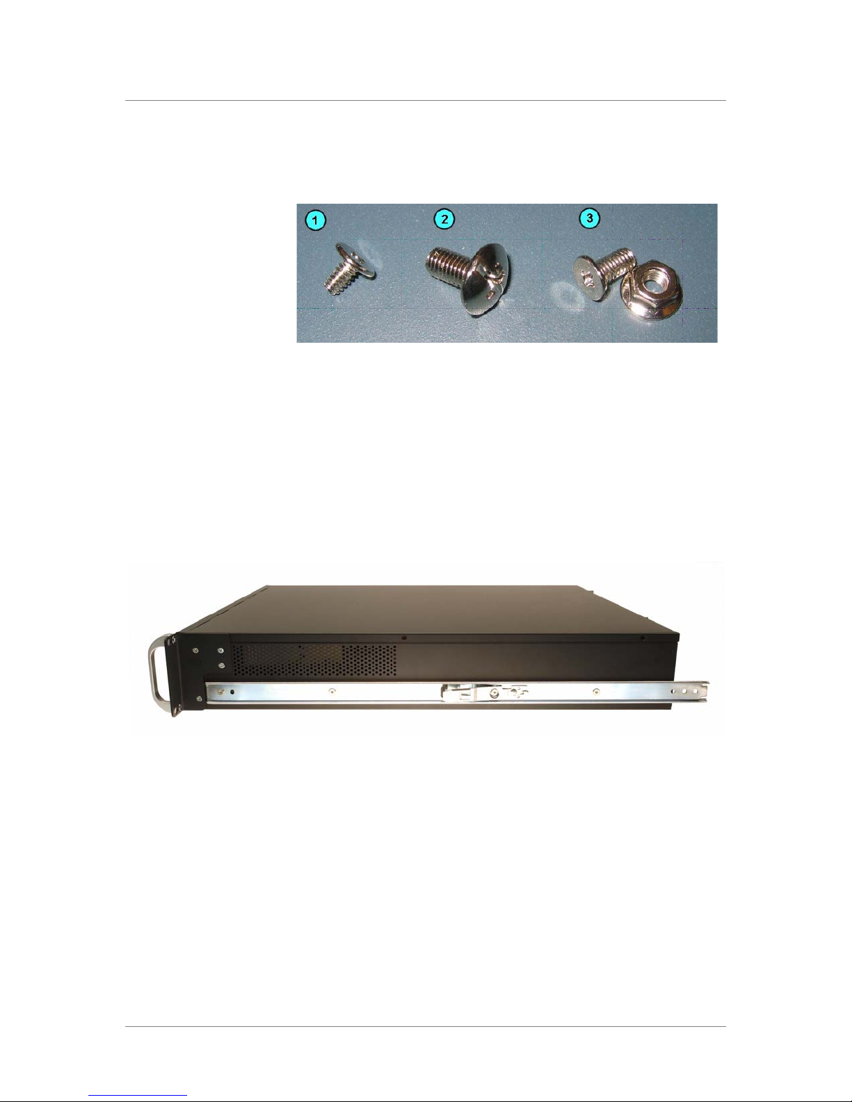
• Set of eight screws for inner rail mount
The eight included pan head Phillips screws attach the inner rail mounts
to the WANJet appliance.
• Set of eight screws for rail-mount brackets
The eight included pan head Phillips/straight slot hybrid screws attach
the rail-mount brackets to the rack. The outer rails fit into these brackets.
• Set of eight nuts and bolts for outer rail mount
Use the included eight pan head Phillips screws and eight flange nuts to
mount the outer rails to the rail-mount brackets.
Platform Guide: WANJet® 500 A - 1
Page 58
Appendix A
Figure A.1 shows the mounting screws that are included with the kit
hardware.
Figure A.1 The three types of mounting screws included with the WANJet
appliance: (1) pan head Phillips, (2) pan head Phillips/straight slot hybrid,
(3) pan head Phillips and flanged nut.
Attaching the inner rails and stops
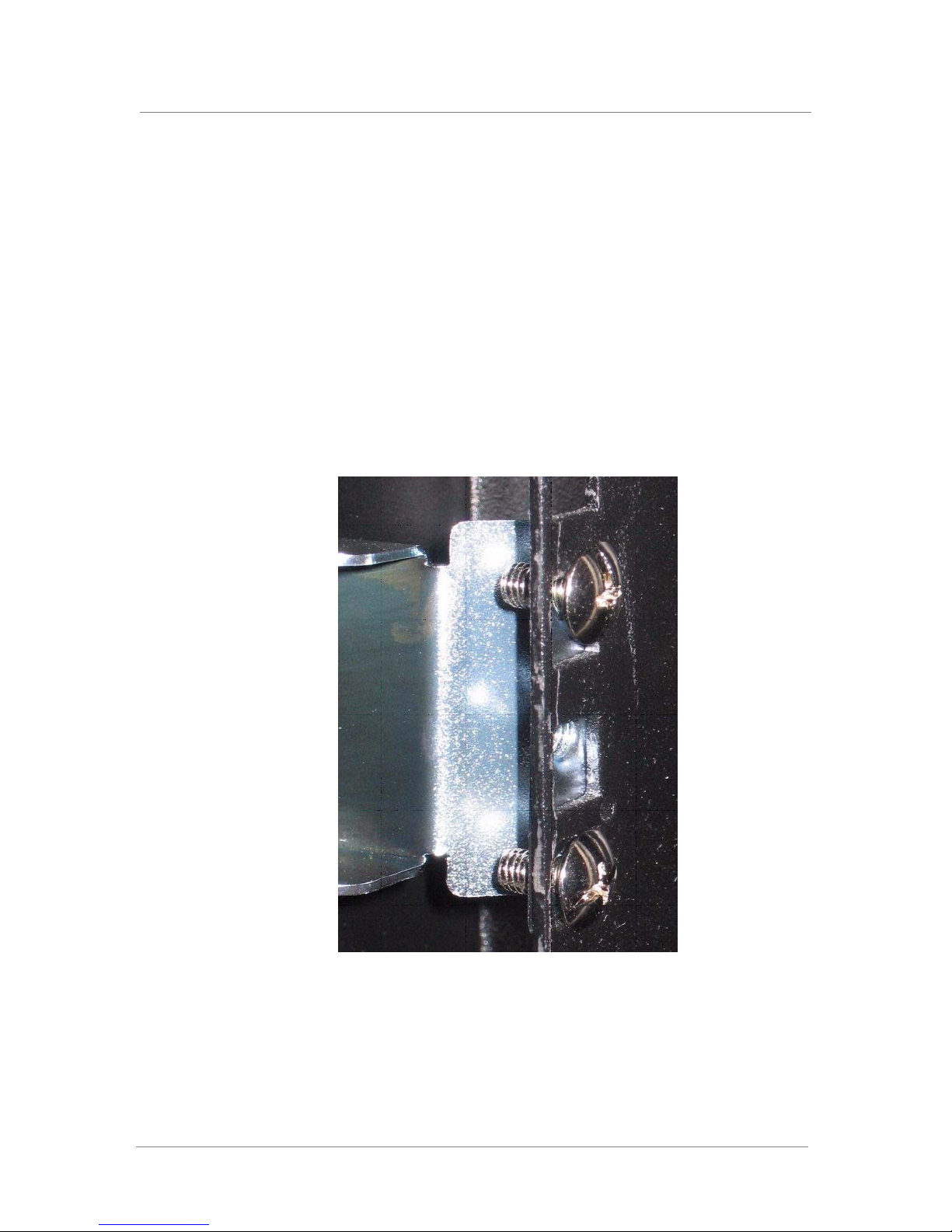
To install the optional rail-mount kit, you must first attach an inner rail and a
stop to each side of the unit. Figure A.2 shows the unit with an inner rail
attached to one side.
Figure A.2 An inner rail attached to the WANJet 500
To attach the inner rails and stops to the unit
1. Prior to attaching the inner rail, separate the rail slides.
The inner rail shown in Figure A.2 slides into the outer rail that
attaches to the rack using the rail-mount brackets.
A - 2
2. Attach an inner rail to each side of the unit, as shown in Figure A.2,
using the pan head Phillips screws included with the system.
Note that each side requires four screws.
Page 59
Attaching the outer rail mounts
The second task in installing the rail-mount kit involves attaching four
mounting brackets to the rack. The mounting brackets provide support for
the outer rails.
After you have installed the inner rails and stops to the unit, you can attach
the four mounting brackets to the rack. The mounting brackets provide
support for the outer rails.
To attach the mounting brackets
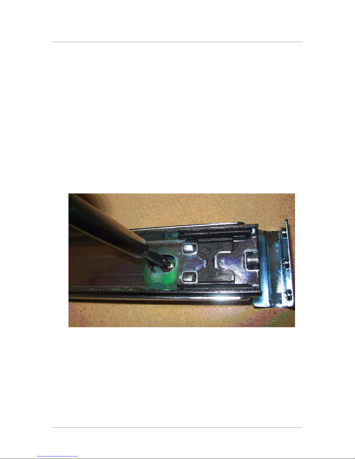
Attach a mounting bracket to each post in the rack, as shown in Figure A.3,
using the pan head Phillips/straight slot hybrid screws included with the
system. Ensure that you use two screws per mount and that you align each
mounting bracket at the same height on each rack post.
Installing the WANJet Appliance Using the Rail-Mount Kit
Platform Guide: WANJet® 500 A - 3
Figure A.3 Mounting bracket attached to rack post
Page 60
Appendix A
Attaching the outer rails
After you have installed the inner rails and stops to the unit, you can attach
the two outer rails to the rack.
Each outer rail fits into the bracket attached to each post. Use the pan head
screws and flanged nuts to attach the outer rail to the mounting brackets.
To attach the outer rails to the rack
1. On one side of the unit, place the rail into the rail mount, and ensure
that the rail slide is not extended.
2. Attach the rail to the front of the mount, as shown in Figure A.4.
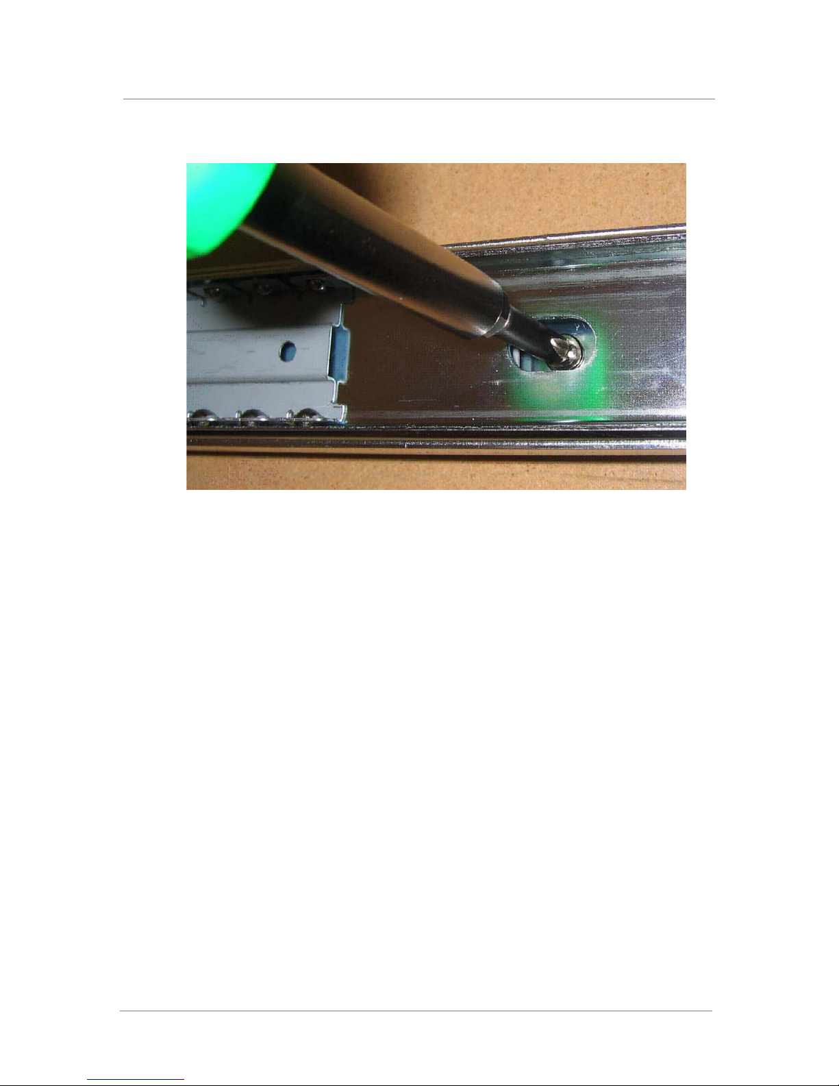
3. Extend the rail to reveal additional screw holes.
4. Attach the rail to the mount as shown in Figure A.5.
5. Repeat this procedure for the rail on the other side.
Figure A.4 Attaching the outer rail to front of the mounting bracket
A - 4
Page 61
Installing the WANJet Appliance Using the Rail-Mount Kit
Figure A.5 Attaching the outer rail after extending the rail slide
Installing the unit into a rail-mount rack
After you have attached the inner rails to the device, and mounted the outer
rails in the rack using the mounting brackets, you can install the device.
To install the unit into the rack
Slide the unit into the rack, fitting the inner rails of the unit to the outer rails
of the rack.
Connecting cables and other hardware
After you have installed the unit into the rack, you need to connect the
cables and other hardware. To perform these tasks, see Connecting the
cables, on page 2-9.
Platform Guide: WANJet® 500 A - 5
Page 62

Appendix A
A - 6
Page 63

B
Platform-Specific Hazardous Substance
Levels, for China
• WJ500, WA4500, and EM3000 platforms
Page 64

Page 65
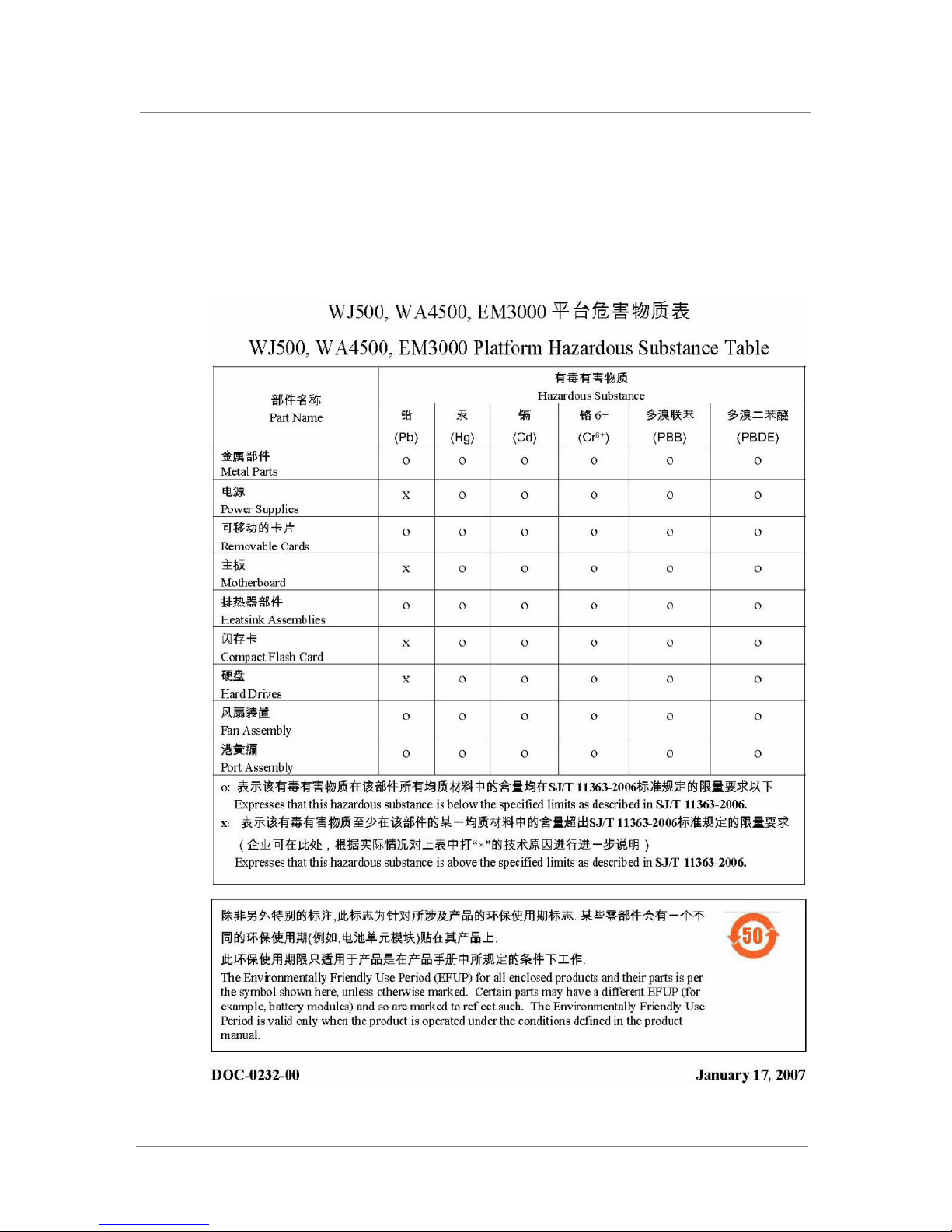
Platform-Specific Hazardous Substance Levels, for China
WJ500, WA4500, and EM3000 platforms
This table lists hazardous substances controlled by China, and shows how
the F5 Networks
conform to the standards.
®
WJ500, WA4500, and EM3000 platform components
Platform Guide: WANJet® 500 B - 1
Page 66

Appendix B
B - 2
Page 67

Glossary
Page 68

Page 69

active unit
Application QoS
Connection Interception (CI)
failover
Glossary
In a redundant system, the active unit is the system that currently optimizes
connections. If the active unit in the redundant system fails, the standby unit
assumes control and begins to optimize connections. See also redundant
system.
Application QoS provides better service for specific data flows by
configuring policies that can adjust the bandwidth consumed by specific
types of network traffic (also referred to as traffic shaping). This way, you
can use the network bandwidth optimally for critical network traffic. See
also Quality of Service (QoS) level.
Connection Interception (CI) intercepts and resets connections that were
initiated before the WANJet appliance became active on the network.
Failover is the process whereby a standby unit in a redundant system takes
over when a software failure or a hardware failure is detected on the active
unit.
field replaceable unit (FRU)
generic routing encapsulation
Layer 1 through Layer 7
LCD
An FRU is a part of the appliance that is replaceable. You can order FRUs to
replace certain parts of the unit including the fan tray, fan filter, drive tray,
and power supply.
Generic routing encapsulation (GRE) tunneling typically connects private IP
networks over an Internet connection using two routers (or switches) that
support GRE encapsulation.
Layers 1 through 7 refer to the seven layers of the Open System
Interconnection (OSI) model. Thus, Layer 1 represents the physical layer,
Layer 2 represents the data-link layer, Layer 3 represents the IP layer, and
Layer 4 represents the transport layer (TCP and UDP). Layer 5 manages
connections between applications, and Layer 6 represents the presentation
layer. Layer 7 represents the application layer, handling traffic such as
HTTP and SSL.
LCD stands for liquid crystal display. An LCD panel is available on the
front of the WANJet 500 platform. You can use the LCD and its associated
keypad to configure the LAN, WAN, and Management ports on the unit and
perform basic administration tasks.
Platform Guide: WANJet® 500 Glossary - 1
Page 70

Glossary
LED indicators
Management port
NIC
OSI model
Peer port
The LED indicators on the front of the WANJet 500 are lights that show the
status of the system.
The Management port on the front of the WANJet 500 can connect to the
management network, if your organization is using out-of-band
management.
A network interface card (NIC) is an expansion board used to connect a
computer to a network.
See Layer 1 through Layer 7.
The Peer port on the front of the WANJet 500 is an Ethernet port that can
connect using a crossover cable to a second WANJet 500 to form a
redundant system. See also redundant system.
Quality of Service (QoS) level
rail mount
redundant system
router
SSL (Secure Sockets Layer)
The Quality of Service (QoS) level is a means by which network equipment
can identify and treat traffic differently based on an identifier. Essentially,
the QoS level specified in a packet enforces a throughput policy for that
packet. See also Application QoS.
A type of mount that attaches rails to the sides of the unit so that you can
slide it in and out of the rack.
Redundant system refers to a pair of units that are configured for failover. In
a redundant system, there are two units, one running as the active unit and
one running as the standby unit. If the active unit fails, the standby unit takes
over and manages connection requests.
A router is a Layer 3 networking device. If no VLANs are defined on the
network, a router defines a broadcast domain.
SSL is a network communications protocol that uses public-key technology
as a way to transmit data in a secure manner.
Glossary - 2
Page 71

standby unit
A standby unit in a redundant system is a unit that is always prepared to
become the active unit if the active unit fails.
Transparent Data Reduction™ (TDR)
TDR technology provides a dramatic reduction in the amount of bandwidth
consumed by repeated data transfers across a WAN link.
Type of Service (ToS) level
The Type of Service (ToS) level is another means, in addition to the Quality
of Service (QoS) level, by which network equipment can identify and treat
traffic differently based on an identifier.
WAN (wide area network)
A WAN is a computer network that spans a large geographic area, and
typically consists of two or more local area networks (LANs). A WAN may
also include public or shared user networks. The most well-known example
of a WAN is the Internet.
Glossary
Web UI
The Web UI is the interface to the WANJet appliance through which you
can configure it and monitor network activity.
Platform Guide: WANJet® 500 Glossary - 3
Page 72

Glossary
Glossary - 4
Page 73

Index
Page 74

Page 75

Index
A
active unit 3-2, 3-3
addresses, configuring 2-6
administrator account, using 2-8
air temperature, operating 5-1
alarm, power supply 4-1
Application QoS 1-8
Ask F5 search engine 1-8
Auto Sense setting 2-8, 3-1
B
battery, lithium warning 5-2
C
cables, connecting 2-9
China material content listing B-1
command line syntax conventions 1-9
command syntax, identifying 1-9
components, provided 1-2, 1-5
config command 2-6
configuration 2-6
Connection Interception (CI) 1-8
console cable 1-3, 1-4, 2-7
console emulator 2-7
console port 1-5
conventions, stylistic 1-8
D
default password 2-8
document cross-reference style 1-9
drive tray replacement 4-2
duplex setting 2-8, 3-1
E
Earth ground 5-1
electrostatic discharge (ESD) 2-2, 5-1
environmental guidelines 5-1
See also hazardous substance restrictions.
See also RoHS compliance.
Ethernet CAT-5e cables 1-3, 2-9
Ethernet hub requirements 1-4
F
failover port 1-6
G
gateway 2-6
Gigabit Ethernet 1-4
grounding, providing 2-2
H
hard drives
locating the drives 1-5
replacing the drives 4-2
hardware components
and environmental guidelines 5-1
connecting peripherals 1-4
of rail-mount kit A-1
unpacking shipping box 1-2
viewing back panel 1-6
viewing front panel 1-5
hardware installation
connecting cables 2-9
mounting in rack 2-1
planning 2-1
hardware requirements, for peripherals 1-4
hardware specifications 6-1
hazardous substance restrictions
and RoHS compliance 1-1
for China B-1
hot swappable hard drive 4-2
hot swappable power supply 4-1
hubs 1-4
HyperTerminal 2-7
I
inactive unit 3-3
indicator lights 1-5
inner rail A-2
installation 2-1
See also hardware installation, and rack-mount
installation.
interface speed 2-8
IP address
configuring 2-6
determining default 2-5
pinging 3-3
L
LAN port 1-5, 2-9
Layer 5 1-1
LCD keypad
and administration 3-3
configuring the unit 3-3
restarting the unit 3-4
setting addresses 2-6
setting operational mode 3-3
shutting down the unit 3-4
using the ping command 3-3
LCD panel
displaying IP address 2-5
locating the LCD 1-5
operating 3-1
Platform Guide: WANJet® 500 Index - 1
Page 76

Index
LED indicators
and functions 3-5
and network interface card 3-6
locating status indicators 1-5
link activity and speed 3-6
liquid crystal display
See LCD keypad.
lithium battery, warning 5-2
M
Management port 1-4, 1-5, 2-9
media types 2-8
mount options 2-1
mounting brackets, attaching A-3
mounting screws, rail kit A-2
N
network cables, connecting 2-9
NIC LEDs 3-6
NIC ports 3-6
O
operational mode 3-3
OSI model 1-1
outer rail mounts A-3
outer rails A-4
P
panel
operating LCD 3-1
panel, front 1-5
parts, provided 1-2, 1-5
password, admin 2-8
PC connection 2-7
Peer port 1-5, 1-6
peripheral hardware 1-4
ping command 3-3
platform
and components provided 1-2
configuring addresses 2-6
determining IP address 2-5
installing in rack 2-1
powering up 2-5
reviewing hardware specifications 6-1
See also China material content listing.
ports 1-5
See also LAN port, Management port, NIC ports,
and Peer port.
power cables 1-3
power supply
and alarm 4-1
replacing 4-1
setting up redundant 2-5
power-up process 2-5
Q
Quick Start Card 1-8
R
rack-mount ears
description A-1
installing 2-2
rack-mount installation
and recommendations 5-1
performing 2-2
rack-mount screws 2-2
rail stop A-2
rail-mount kit
installing A-1
using optional 2-1
rails
attaching inner rails A-2
attaching outer rail mounts A-3
attaching outer rails A-4
redundant power supply 2-5, 4-1
redundant system 1-6
references
identifying commands 1-9
identifying other documents 1-9
release notes 1-8
remote administration 1-4
restart process 3-4
RoHS compliance 1-1
See also China material content listing.
router, connecting to 2-9
S
safe installation recommendations 5-1
screw types A-2
serial console
for hardware installation 1-4
setting addresses 2-7
serial port console cable 1-3, 1-4, 2-7
serviceability 5-2
shelf kit 2-2
shut down process 3-4
snapshot
sending in email 3-4
solution examples 1-8
spacing between units 2-1
specifications
for China, material content B-1
platform 6-1
Index - 2
Page 77

stylistic conventions 1-8
subnet mask 2-6
switches 1-4
syntax, command 1-9
system snapshot 3-4
T
technical support 1-8
Transparent Data Reduction (TDR) 1-1, 1-8
Type of Service (ToS) 1-8
U
USB keyboard 1-5
USB port 1-5
V
ventilation 5-1
W
WAN port 1-5, 2-9
warnings, environmental 5-1
See also China material content listing.
See also RoHS compliance.
Web UI 1-8, 2-6, 2-8, 3-1, 3-2
Index
Platform Guide: WANJet® 500 Index - 3
 Loading...