

Page 1

Platform Guide: 8400 and 8800
MAN-0232-02
Page 2

Page 3

Product Version
Publication Date
Legal Notices
This manual applies to the 8400 and 8800 platforms created by F5 Networks, Inc.
This guide was published on July 26, 2010.
Copyright
Copyright 2007-2010, F5 Networks, Inc. All rights reserved.
F5 Networks, Inc. (F5) believes the information it furnishes to be accurate and reliable. However, F5
assumes no responsibility for the use of this information, nor any infringement of patents or other rights of
third parties which may result from its use. No license is granted by implication or otherwise under any
patent, copyright, or other intellectual property right of F5 except as specifically described by applicable
user licenses. F5 reserves the right to change specifications at any time without notice.
Trademarks
F5, F5 Networks, the F5 logo, BIG-IP, 3-DNS, iControl, Internet Control Architecture, IP Application
Switch, iRules, OneConnect, Packet Velocity, SYN Check, Control Your World, ZoneRunner, uRoam,
FirePass, TrafficShield, Swan, WANJet, WebAccelerator, and TMOS are registered trademarks or
trademarks, and Ask F5 is a service mark, of F5 Networks, Inc. in the U.S. and certain other countries. All
other trademarks mentioned in this document are the property of their respective owners. F5 Networks'
trademarks may not be used in connection with any product or service except as permitted in writing by
F5.
Export Regulation Notice
This product may include cryptographic software. Under the Export Administration Act, the United States
government may consider it a criminal offense to export this product from the United States.
RF Interference Warning
This is a Class A product. In a domestic environment this product may cause radio interference, in which
case the user may be required to take adequate measures.
FCC Compliance
This equipment has been tested and found to comply with the limits for a Class A digital device pursuant
to Part 15 of FCC rules. These limits are designed to provide reasonable protection against harmful
interference when the equipment is operated in a commercial environment. This unit generates, uses, and
can radiate radio frequency energy and, if not installed and used in accordance with the instruction manual,
may cause harmful interference to radio communications. Operation of this equipment in a residential area
is likely to cause harmful interference, in which case the user, at his own expense, will be required to take
whatever measures may be required to correct the interference.
Any modifications to this device, unless expressly approved by the manufacturer, can void the user's
authority to operate this equipment under part 15 of the FCC rules.
Canadian Regulatory Compliance
This Class A digital apparatus complies with Canadian ICES-003.
Standards Compliance
This product conforms to the IEC, European Union, ANSI/UL and Canadian CSA standards applicable to
Information Technology products at the time of manufacture.
Platform Guide: 8400 and 8800 i
Page 4
VCCI Class A Compliance
This is a Class A product. In a domestic environment, this product may cause radio interference, in which
case the user may be required to take corrective actions.
ii
Page 5

Table of Contents
Page 6

Page 7

1
Introducing the IP Application Switch Platform
Working with the IP Application Switch platform ..................................................................1-1
Getting started with the 8400 and 8800 platforms ................................................................1-2
Components provided with the IP Application Switch .................................................1-2
Peripheral hardware that you provide ..............................................................................1-3
Familiarizing yourself with the IP Application Switch .............................................................1-4
Using the IP Application Switch hardware .......................................................................1-4
About this guide ..............................................................................................................................1-6
Finding additional information .............................................................................................1-7
Stylistic conventions ..............................................................................................................1-8
Finding help and technical support resources ....................................................................... 1-10
2
Installing the IP Application Switch Platform
Installing and connecting the hardware .....................................................................................2-1
General recommendations for mounting a unit in a rack ............................................2-1
Installing the IP Application Switch hardware .................................................................2-2
Connecting the cables and other hardware ....................................................................2-4
Table of Contents
3
Operating the LCD Panel
Introducing the LCD panel ...........................................................................................................3-1
Using the LCD panel ......................................................................................................................3-2
Pausing on a screen ...............................................................................................................3-2
Accessing LCD menus ..........................................................................................................3-2
Powering up the unit .............................................................................................................3-2
Halting the unit .......................................................................................................................3-2
Powering down the unit .......................................................................................................3-3
Rebooting the unit .................................................................................................................3-3
Clearing alerts .........................................................................................................................3-3
Navigating through the LCD menus ...........................................................................................3-4
Information menu ..................................................................................................................3-4
System menu ...........................................................................................................................3-5
Screens menu ..........................................................................................................................3-6
Options menu .........................................................................................................................3-7
4
Using Additional IP Application Switch Functionality
Understanding LED behavior .......................................................................................................4-1
Indicator LED functions ........................................................................................................4-1
Indicator LED actions ...........................................................................................................4-1
Standard operating states ....................................................................................................4-2
Alert conditions indicated by the Alarm LED .................................................................4-2
Configuring indicator LEDs to display node status ........................................................4-2
Specific status indicated by the LEDs ................................................................................4-3
Working with interfaces ................................................................................................................4-5
Displaying status and settings for interfaces ....................................................................4-5
Media type and duplex mode ..............................................................................................4-6
Hardware acceleration ..................................................................................................................4-7
Platform Guide: 8400 and 8800 v
Page 8

Table of Contents
5
Maintaining the IP Application Switch Platform
Reviewing maintenance options and operations .....................................................................5-1
Changing the fan tray and filter ...................................................................................................5-1
Replacing the fan tray and filter ..........................................................................................5-1
Changing a power supply ..............................................................................................................5-3
Replacing the power supply .................................................................................................5-3
Changing the drive tray .................................................................................................................5-5
Replacing the drive tray ........................................................................................................5-5
6
Working with Environmental Guidelines for the IP Application Switch Platform
Environmental requirements ........................................................................................................6-1
General environmental guidelines ......................................................................................6-1
Guidelines for DC-powered equipment ...........................................................................6-2
7
Understanding Platform Airflow
Reviewing platform airflow information ....................................................................................7-1
Airflow for the 8400/8800 platform ..................................................................................7-1
8
Reviewing Hardware Specifications
Reviewing hardware specifications .............................................................................................8-1
8400 specifications ..........................................................................................................................8-2
8800 specifications ..........................................................................................................................8-3
Additional acoustic, airflow, and altitude specifications .........................................................8-4
A
Installing an IP Application Switch Using an Optional Rail-Mount Kit
Installing the optional rail-mount kit ..........................................................................................A-1
Removing standard mount hardware from the unit .....................................................A-1
Installing the kit hardware ..................................................................................................A-2
Installing the unit into a rail-mount rack .........................................................................A-5
Connecting cables and other hardware ..........................................................................A-5
B
Platform-Specific Hazardous Substance Levels, for China
8400 platform ................................................................................................................................. B-1
8800 platform ................................................................................................................................. B-2
Glossary
Index
vi
Page 9

1
Introducing the IP Application Switch
Platform
• Working with the IP Application Switch platform
• Getting started with the 8400 and 8800 platforms
• Familiarizing yourself with the IP Application Switch
• About this guide
• Finding help and technical support resources
Page 10

Page 11
Introducing the IP Application Switch Platform
WARNING
Working with the IP Application Switch platform
The IP Application Switch™ platforms are powerful systems capable of
managing traffic for any size of enterprise.
Externally, the IP Application Switch platforms look similar. However,
there are internal differences.
◆ 8400 and 8800 platforms
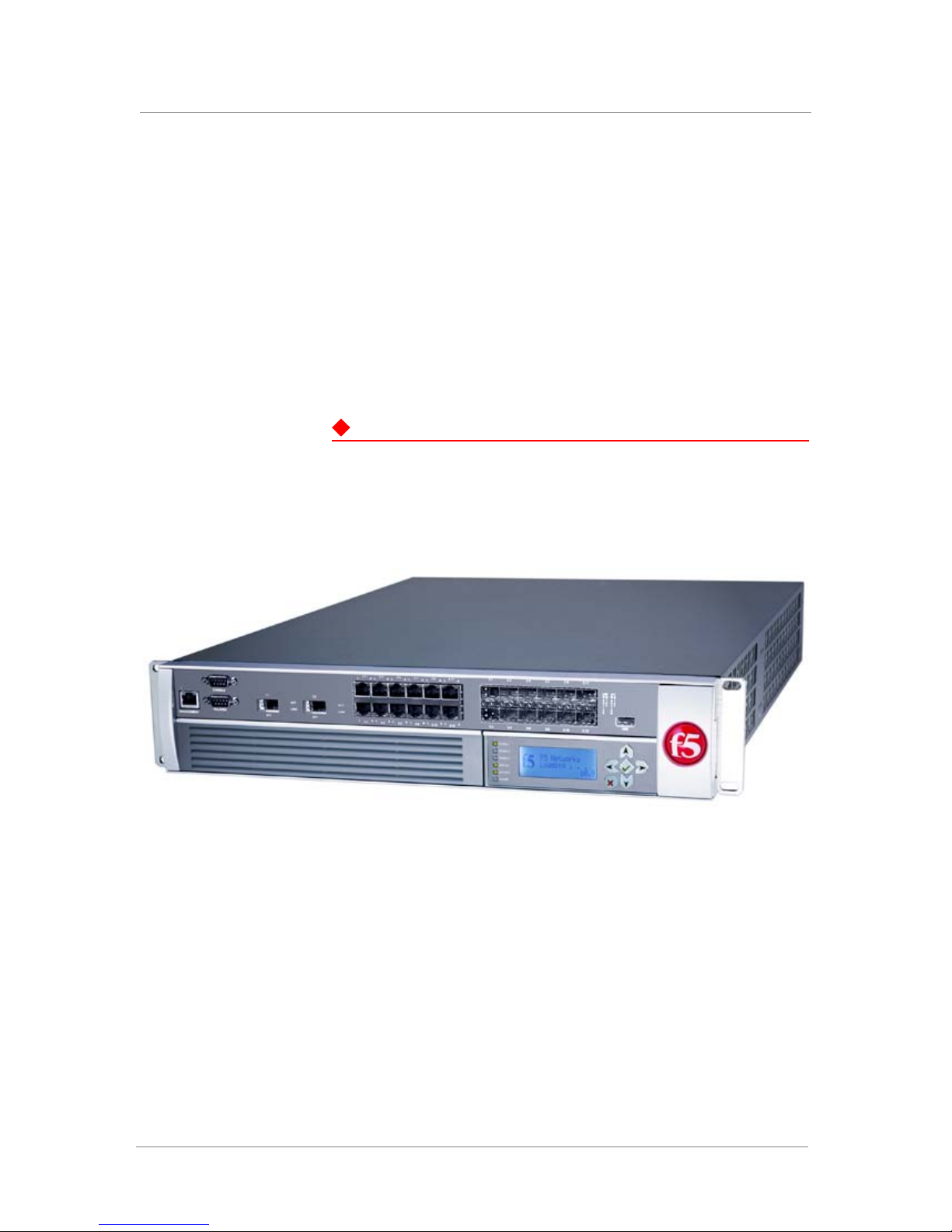
The 8400 and 8800 platforms (Figure 1.1) support two 10 Gigabit XFPs,
twelve fiber small form-factor pluggable (SFP) gigabit interface
converters (GBICs, LC connector type), and twelve copper 10/100/1000
interfaces.
Only optics modules provided by F5 Networks are supported in this
platform.
For detailed specifications of each platform, see Reviewing hardware
specifications, on page 8-1.
Figure 1.1 This is an external view of the 8400/8800 platform
Platform Guide: 8400 and 8800 1 - 1
Page 12

Chapter 1
Getting started with the 8400 and 8800 platforms
There are several basic tasks you must complete to get the IP Application
Switch platform installed and set up.
• Review the hardware requirements. For more information about the
hardware requirements, read the following sections, Components
provided with the IP Application Switch, following, and Peripheral
hardware that you provide, on page 1-3.
• Understand the environmental guidelines. For more information, see
Environmental requirements, on page 6-1.
• Familiarize yourself with the IP Application Switch hardware. For more
information, see Familiarizing yourself with the IP Application Switch,
on page 1-4.
• Connect the IP Application Switch to the network, and optionally
connect the peripheral hardware. For more information on mounting the
hardware and attaching cables, see Installing and connecting the
hardware, on page 2-1.
The IP Application Switch comes with the hardware that you need for
installation. However, you must also provide standard peripheral hardware,
such as a serial terminal, if you want to administer the IP Application Switch
directly.
Components provided with the IP Application Switch
When you unpack the IP Application Switch, you should make sure that the
following components, shown in Figure 1.2, are included:
• One power cable
• One serial failover cable
• Four rack-mounting screws
The power cable included with this unit is for exclusive use with this unit
and should not be used with other electrical appliances.
If you purchased a hardware-based redundant system, you also received one
fail-over cable to connect the two IP Application Switch units together
(network-based redundant systems do not require a fail-over cable).
1 - 2
Page 13
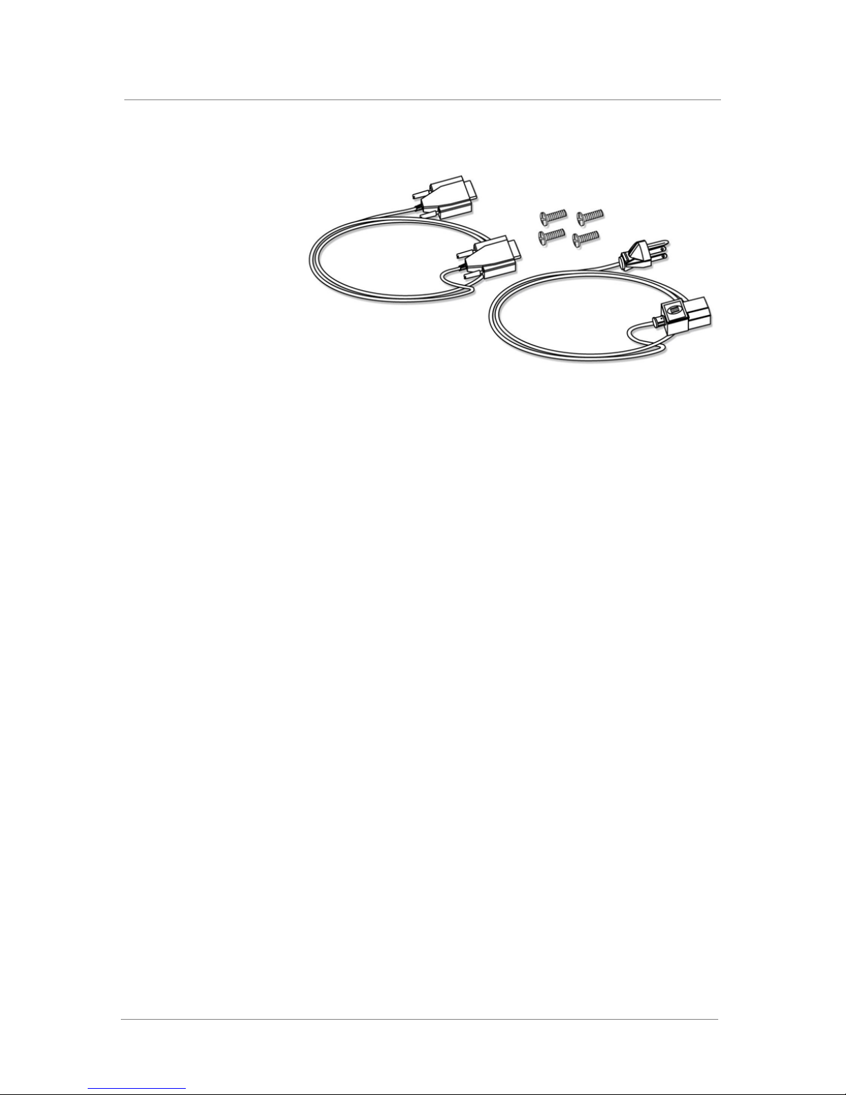
Figure 1.2 Components included with the IP Application Switch
Peripheral hardware that you provide
Introducing the IP Application Switch Platform
For each IP Application Switch in the system, the peripheral hardware you
provide is determined by the configuration you want to create:
◆ If you plan to use direct administrative access to the IP Application
Switch, you need standard input/output hardware. This requires a serial
terminal and a null modem cable.
◆ If you want to use the default IP Application Switch configuration, you
must have an administrative workstation on the same IP network as the
IP Application Switch.
◆ You also need network hubs, switches, or concentrators to connect to the
IP Application Switch network interfaces. The devices you select must
be compatible with the network interface cards installed in the IP
Application Switch. The devices can support 10/100 Ethernet or Gigabit
Ethernet.
• Ethernet requires either a 10 Mbps or 100 Mbps hub or switch.
• Gigabit Ethernet requires a compatible Gigabit Ethernet switch.
◆ You can use a USB drive compatible with the system for installing
upgrades and for system recovery. You can perform an upgrade or
system recovery with almost any non-CDRW USB drive. Even though
most USB CD-ROMS should work, we cannot guarantee compatibility
with all makes and models.
If you plan on doing remote administration from your own PC workstation
as most users do, we recommend that you have your workstation already in
place on the same subnet to which the management interface is connected.
Platform Guide: 8400 and 8800 1 - 3
Page 14
Chapter 1
Familiarizing yourself with the IP Application Switch
The IP Application Switch comes in several different hardware
configurations. Before you begin to install the IP Application Switch, you
may want to quickly review the following figures that illustrate the controls
and ports on both the front and the back of an IP Application Switch.
Using the IP Application Switch hardware
You need to be familiar with both the front and back layout of an IP
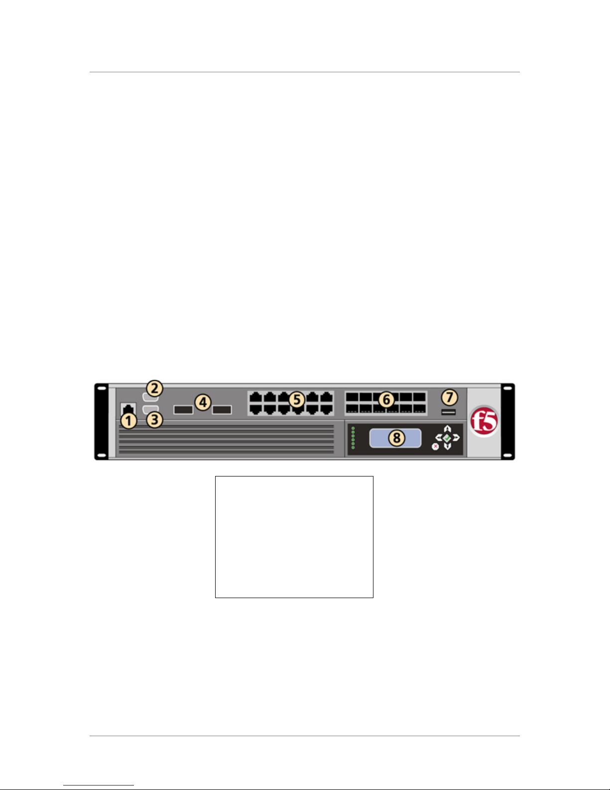
Application Switch. Figure 1.3 illustrates the front of an 8400/8800 series IP
Application Switch. On the front of the unit, you can use the LCD panel to
turn the unit off and on, or you can reset the unit. You can also view the
indicator lights for hard disk access.
The interfaces on every IP Application Switch are labeled, so it should be
clear what each port is, no matter which hardware configuration you have
purchased. Note that the USB port, number 7 in Figure 1.3, is oriented so
that you can plug the cable in with the correct side up. Previous platforms
required you to plug the cable in upside down.
1. 10/100 Ethernet Management interface
2. Console port
3. Hard-wired fail-over port
4. XFP interfaces
5. 10/100/1000 Copper interfaces
6. 1000 Fiber interfaces
7. USB port
8. LCD readout and buttons
Figure 1.3 Front view of the model 8400/8800 IP Application Switch
1 - 4
If you have physical access to the unit, you can use the front-panel LEDs to
assess the condition of the unit. For details about the behavior of the LEDs,
see Understanding LED behavior, on page 4-1.
Page 15
Introducing the IP Application Switch Platform
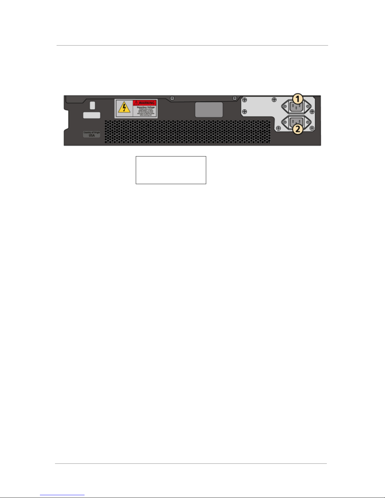
Figure 1.4, following, illustrates the back of a IP Application Switch. Note
that all ports are labeled.
1. Power supply 1
2. Power supply 2 (optional)
Figure 1.4 Back view of the IP Application Switch with power input panel
Platform Guide: 8400 and 8800 1 - 5
Page 16

Chapter 1
About this guide
This guide describes the features of the 8400 and 8800 IP Application
Switch platforms. This guide contains the following information about these
platforms.
• Installing the hardware
You can learn how to install the hardware in a rack. For more
information, see Chapter 2, Installing the IP Application Switch
Platform.
• Understanding the ports and interfaces
You can understand the intended use of the ports and interfaces on each
platform. For more information, see Familiarizing yourself with the IP
Application Switch, on page 1-4.
• Using the LCD panel
You can learn how to understand and use the LCD panel. For more
information see Chapter 3, Operating the LCD Panel.
• Understanding LED behavior
You can learn how to decipher what conditions are signaled by the
LEDs. For more information, see Understanding LED behavior, on page
4-1.
• Replacing a fan tray and filter
You can learn how to replace a fan tray and filter. For more information
see Changing the fan tray and filter, on page 5-1.
• Changing a power supply
You can learn how to replace a power supply. For more information, see
Changing a power supply, on page 5-3.
• Replacing the drive tray
You can learn how to replace the tray that contains the drives for the
system. for more information, see Changing the drive tray, on page 5-5.
• Understanding the environmental guidelines
This chapter includes detailed environmental guidelines for each
platform. For more information, see Chapter 6, Working with
Environmental Guidelines for the IP Application Switch Platform.
• Understanding platform airflow
You can read detailed airflow information for each platform. For more
information, see Chapter 7, Understanding Platform Airflow.
• Learning the hardware specifications
This chapter provides details about the hardware specifications for each
platform. For more information, see Chapter 8, Reviewing Hardware
Specifications.
1 - 6
Page 17

Finding additional information
Introducing the IP Application Switch Platform
In addition to this guide, there are other sources of documentation you can
use in order to work with the BIG-IP
®
platform. The information is available
in the guides and documents described below. The following printed
documentation is included with the BIG-IP system.
◆ Configuration Worksheet
This worksheet provides you with a place to plan the basic configuration
for the BIG-IP system.
◆ BIG-IP Quick Start Instructions
This pamphlet provides you with the basic configuration steps required
to get the BIG-IP system up and running in the network.
The following guides are available from the Ask F5
SM
web site
(https://support.f5.com).
◆ Installation, Licensing, and Upgrades for BIG-IP Systems
This guide provides detailed information about installing upgrades to the
BIG-IP system. It also provides information about licensing the BIG-IP
system software and connecting the system to a management workstation
or network.
◆ Configuration Guide for BIG-IP Local Traffic Management
This guide contains any information you need for configuring the BIG-IP
system to manage local network traffic. With this guide, you can perform
tasks such as creating virtual servers and load balancing pools,
configuring application and persistence profiles, implementing health
monitors, and setting up remote authentication.
◆ BIG-IP Network and System Management Guide
This guide contains any information you need to configure and maintain
the network and system-related components of the BIG-IP system. With
this guide, you can perform tasks such as configuring VLANs, assigning
self IP addresses, creating administrative user accounts, and managing a
redundant system.
Platform Guide: 8400 and 8800 1 - 7
Page 18

Chapter 1
Stylistic conventions
To help you easily identify and understand important information, our
documentation uses the stylistic conventions described below.
Using the solution examples
All examples in this documentation use only private class IP addresses.
When you set up the solutions we describe, you must use valid IP addresses
suitable to your own network in place of our sample addresses.
Identifying new terms
To help you identify sections where a term is defined, the term itself is
shown in bold italic text. For example, a virtual server is a specific
combination of a virtual address and virtual port, associated with a content
site that is managed by a BIG-IP system or other type of host server.
Identifying references to objects, names, and commands
We apply bold text to a variety of items to help you easily pick them out of a
block of text. These items include web addresses, IP addresses, utility
names, and portions of commands, such as variables and keywords. For
example, with the bigpipe pool <pool_name> show command, you can
specify a specific pool to show by specifying a pool name for the
<pool_name> variable.
Identifying references to other documents
We use italic text to denote a reference to another document. In references
where we provide the name of a book as well as a specific chapter or section
in the book, we show the book name in bold, italic text, and the
chapter/section name in italic text to help quickly differentiate the two. This
is an example of a reference:
For details about connecting the system to a management workstation or
network, see Chapter 2, Connecting a Management Workstation or Network,
in Installation, Licensing, and Upgrades for BIG-IP Systems.
1 - 8
Page 19

Identifying command syntax
We show complete commands in bold Courier text. Note that we do not
include the corresponding screen prompt, unless the command is shown in a
figure that depicts an entire command line screen. For example, the
following command shows the configuration of the specified pool name:
bigpipe pool <pool_name> show
or
b pool <pool_name> show
Table 1.1 explains additional special conventions used in command line
syntax.
Item in text Description
Introducing the IP Application Switch Platform
\ Indicates that the command continues on the following line, and that users should type the entire
< > Identifies a user-defined parameter. For example, if the command has <your name>, type in your
| Separates parts of a command.
[ ] Indicates that syntax inside the brackets is optional.
... Indicates that you can type a series of items.
::= Means is defined as. Indicates that an argument is followed by the description of the elements that
command without typing a line break.
name, but do not include the angle brackets.
you can use for the argument.
Table 1.1 Command line syntax conventions
Platform Guide: 8400 and 8800 1 - 9
Page 20

Chapter 1
Finding help and technical support resources
You can find additional technical documentation and product information in
the following locations:
◆ Online help for local traffic management
The Configuration utility has online help for each screen. The online help
contains descriptions of each control and setting on the screen. Click the
Help tab in the left navigation pane to view the online help for a screen.
◆ Welcome screen in the Configuration utility
The Welcome screen in the Configuration utility contains links to many
useful web sites and resources, including:
• The F5 Networks Technical Support web site
• The F5 Solution Center
• The F5 DevCentral web site
• Plug-ins, SNMP MIBs, and SSH clients
◆ F5 Networks Technical Support web site
The F5 Networks Technical Support web site, https://support.f5.com,
provides the latest documentation for the product, including:
• Release notes for the product, current and past
• Updates for guides (in PDF form)
• Technical notes
• Answers to frequently asked questions
• The Ask F5 natural language question and answer engine
To access this site, you need to register at https://support.f5.com.
1 - 10
Page 21

2
Installing the IP Application Switch Platform
• Installing and connecting the hardware
Page 22

Page 23

Installing the IP Application Switch Platform
Installing and connecting the hardware
After you have reviewed the hardware requirements and become familiar
with the IP Application switch, as described in Getting started with the 8400
and 8800 platforms, on page 1-2, you can install the unit.
There are two types of mounts available to hold the IP Application Switch:
the standard front-rack mount that comes with the IP Application Switch,
and an optional rail mount that allows you to slide the unit in and out as
needed. The tasks you need to perform to install the IP Application Switch
hardware differ depending on which type of mount you decide to use:
◆ Standard front mount
If you want to install the IP Application Switch into the standard
front-rack mount that comes with the hardware, you need to install the
unit into the rack, and then connect the peripheral hardware and the
interfaces. For detailed information, see Installing the IP Application
Switch hardware, on page 2-2, and Connecting the cables and other
hardware, on page 2-4.
◆ Optional rail mount
If you want to install the IP Application Switch into a rail mount (using
the optional rail-mount kit), you need to perform two preliminary steps.
• First, you must remove the standard mount-related hardware (known
as rack-mount ears) from the unit, because the mount hardware is no
longer necessary.
• Second, you must install the optional rail-mount kit.
Once you have completed these tasks, you can then install the unit into
the rack and connect the cables and other hardware. For detailed
information on installing a rail-mount kit and installing the unit into the
rack, see Appendix A, Installing an IP Application Switch Using an
Optional Rail-Mount Kit. For information on connecting the cables and
other hardware, see Connecting the cables and other hardware, on page
2-4.
Whether you are using the standard front mount or the optional rail mount,
you should read the following general recommendations before proceeding
with the installation of the IP Application Switch.
General recommendations for mounting a unit in a rack
We recommend that all units have 1U spacing between them when mounted
in a rack to allow for a rack mounting shelf, and to provide additional air
circulation for cooling the unit.
Although not required, a 1U space between units makes it easier for you to
remove the unit from the rack in the event that the unit requires service. A
1U space between units also provides additional cable routing options.
Platform Guide: 8400 and 8800 2 - 1
Page 24

Chapter 2
WARNING
WARNING
WARNING
We recommend 100 mm spacing from the front panel of the unit to the rack
front or rack door. This provides enough room for you to route the cables
without bending them excessively.
For systems configured with the DC power option, this product is designed
for installation in a restricted access location. A readily accessible
disconnect must be incorporated in the wiring for the installation.
This product is sensitive to electrostatic discharge (ESD). We recommend
that when you install or maintain the unit, you use proper ESD grounding
procedures and equipment.
Do not turn on an IP Application Switch until the management serial
console and/or the management network is connected to the unit.
Installing the IP Application Switch hardware
If you want to use the standard front mount to hold the IP Application
Switch unit, use the following procedure, To install the unit into a
standard-mount rack.
If you are using the optional rail mount kit to hold the unit, use the
procedures described in Appendix A, Installing an IP Application Switch
Using an Optional Rail-Mount Kit. The appendix describes how to perform
the two preliminary tasks of removing the standard mount hardware from
the unit and adding the rail hardware to the unit and the rack. The appendix
also describes how to install the unit into the rack.
A shelf or similar device is required to support the unit if a single person is
installing the unit. To prevent personal injury or damage to the unit, we
recommend that at least two people perform the installation.
To install the unit into a standard-mount rack
1. Lift the unit into place.
2. Secure the unit using the four rack-mounting screws that are
provided.
The unit must be securely fastened to the rack to provide adequate
stability and to prevent the unit from falling out of the rack.
Securing the rack with the screws also provides adequate grounding.
2 - 2
If the rack you have does not provide adequate support for the unit, you may
need a shelf kit. We recommend that you use a shelf kit created by the rack
manufacturer. (Some rack manufacturers provide shelf kits for their racks.)
Page 25
Installing the IP Application Switch Platform
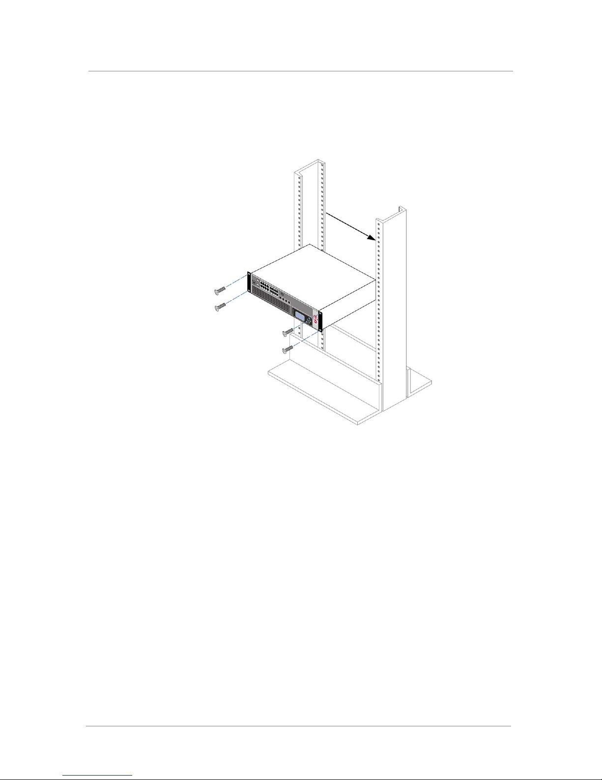
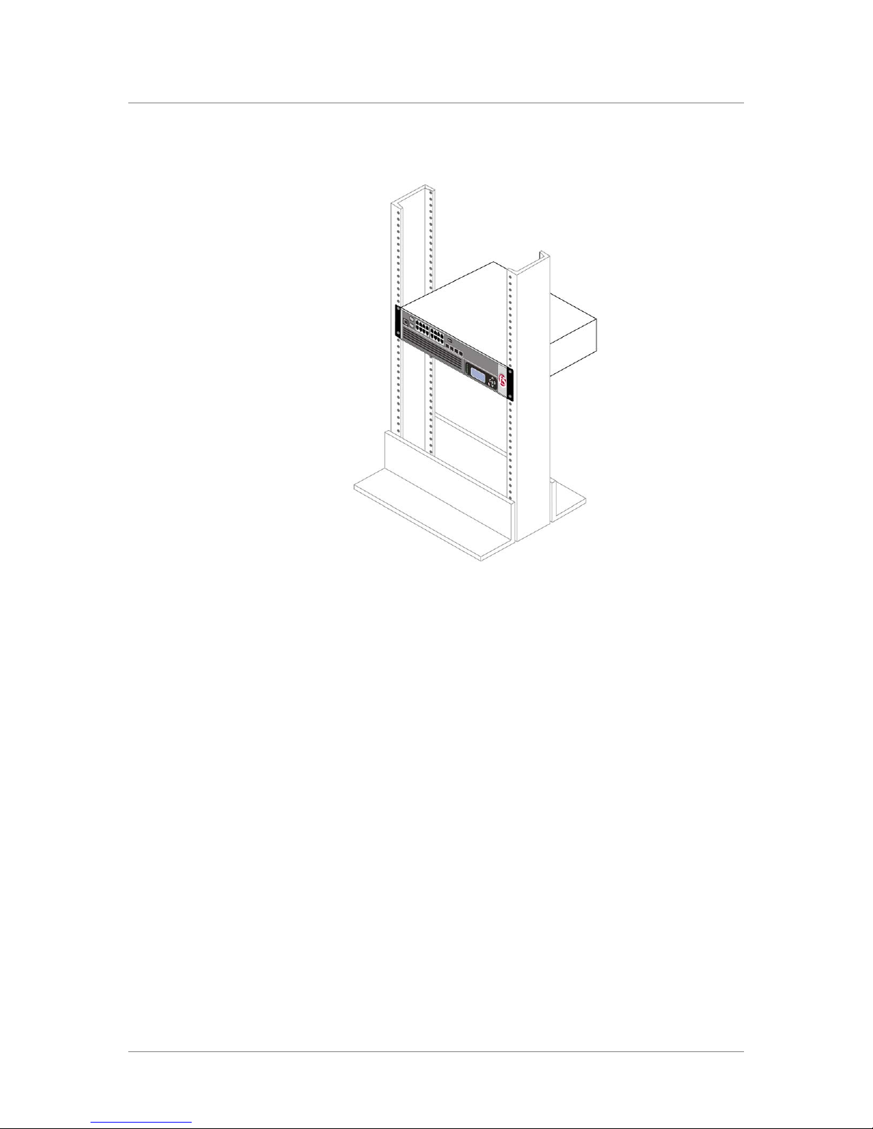
Figure 2.1 shows the orientation of the IP Application Switch and the
mounting screws for installation in a standard 19" rack. Figure 2.2,
following, shows the IP Application Switch installed in the rack.
Figure 2.1 Platform orientation for rack mounting
Platform Guide: 8400 and 8800 2 - 3
Page 26
Chapter 2
Figure 2.2 Platform installed in a 19" rack
Regardless of which mount type you install the unit into, you finish the
installation by connecting the cables and other hardware. This procedure is
described in Connecting the cables and other hardware, following.
Connecting the cables and other hardware
After you have installed the unit into the rack, you need to connect certain
cables and other hardware. To perform these tasks, use the following
procedure. Note that you use this procedure regardless of the type of mount
you installed (front mount or rail mount).
To connect the cables and hardware for input/output
1. Connect the hardware that you have chosen to use for input/output.
For details about connecting the system to a management
workstation or network, see Chapter 2, Connecting a Management
Workstation or Network, in Installation, Licensing, and Upgrades
for BIG-IP Systems.
• If you are using a serial terminal as the console, connect the serial
cable supplied by F5 Networks to the console port (number 2 in
Figure 1.3, on page 1-4).
2 - 4
Page 27

Installing the IP Application Switch Platform
• If you are using an Ethernet connection, connect a management
workstation to the management interface (number 1 in Figure 1.3,
on page 1-4).
2. If you have a hardware-based redundant system, connect the
fail-over cable to the fail-over port on each unit (number 3 in Figure
1.3, on page 1-4).
3. Connect the power cable to the power input panel (number 2 in
Figure 1.4, on page 1-5), and then connect it to the power source. If
the system has the DC power option, a readily accessible disconnect
must be incorporated in the wiring for the installation.
4. Turn on the unit and begin licensing the system. For details about
licensing the BIG-IP system, see Chapter 3, Licensing and
Configuring the BIG-IP System, in Installation, Licensing, and
Upgrades for BIG-IP Systems.
Platform Guide: 8400 and 8800 2 - 5
Page 28

Chapter 2
2 - 6
Page 29

3
Operating the LCD Panel
• Introducing the LCD panel
• Using the LCD panel
• Navigating through the LCD menus
Page 30

Page 31
Introducing the LCD panel
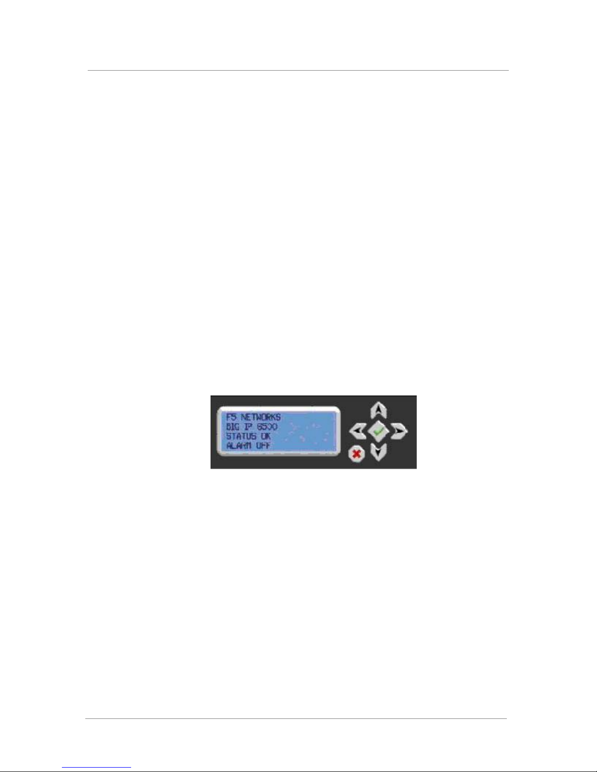
The liquid crystal display, or LCD panel, provides the ability to control the
unit without attaching a serial or network cable. The LCD panel provides
menus with options that provide the ability to configure certain features on
the system. The following menus are available on the LCD panel.
◆ Information menu
Use the Information menu to find information about using the LCD and
its functionality.
◆ System menu
Use the System menu to reboot, netboot, or halt the unit. This menu also
has options for setting the properties of the management interface
(MGMT) and the serial port.
◆ Screens menu
Use the Screens menu to set up the informational screens you would like
the LCD to cycle through. The information screens include system status,
statistics, and system alerts.
◆ Options menu
Use the Options menu to configure the properties of the LCD panel.
Operating the LCD Panel
This chapter describes how to use the LCD panel and its menus.
Figure 3.1 An example of the LCD panel and control buttons
Platform Guide: 8400 and 8800 3 - 1
Page 32

Chapter 3
Using the LCD panel
You can configure the LCD panel to meet your needs. The following section
describes how to perform a number of tasks with the LCD panel:
• Pause on a screen
• Access the LCD menus
• Power up the unit
• Halt the unit
• Power down the unit
• Reboot the unit
• Clear alerts
Pausing on a screen
Normally, the screens cycle on the LCD at a constant rate. However, you
can push the Check button to toggle the LCD between Hold and Rotate
modes. In Hold mode, a single screen is displayed. The Rotate mode
changes the screen displayed on the LCD every 4 seconds.
Accessing LCD menus
Press the X button to put the LCD panel in Menu mode so you can access
the menus. The buttons Left Arrow, Right Arrow, Up Arrow, and Down
Arrow are only functional when the LCD is in Menu mode. For more
information about using the LCD menus, see Navigating through the LCD
menus, on page 3-4.
Powering up the unit
When you want to power up a unit that is shut down, press the Check button
to turn the power on.
Halting the unit
We recommend you halt the unit before you power it down or reboot it
using the LCD menu options.
To halt the unit
1. Press the X button, then use the arrow keys to navigate to the
System menu.
3 - 2
2. Press the Check button. Navigate to the Halt menu.
Page 33

3. Press the Check button. Press the Check button again at the
4. Wait 30 seconds before powering the machine off or rebooting it.
Powering down the unit
Hold the X button for 4 seconds to power down the unit. We recommend
that you halt the system before you power down the unit in this manner.
Halting the unit puts the chassis into a powered on, but quiet state where the
LCD has power and its keypad is dimly lit, but everything else is off. Simply
pressing the green Check button again powers the unit back on.
The system is designed to remember the state of the chassis soft power state
even when the AC power is removed, and to restore that state when AC
power is reapplied. If you power off the chassis using the Check button and
then disconnect the power cord, the power state of the chassis returns to the
soft powered off state when you reconnect the power cord.
Operating the LCD Panel
confirmation screen.
Rebooting the unit
Clearing alerts
Hold the Check button for 4 seconds to reboot the unit. You should only use
this option after you halt the unit.
Press the Check button to clear any alerts on the LCD screen. You must
clear any alerts on the screen before you can use the LCD.
Platform Guide: 8400 and 8800 3 - 3
Page 34

Chapter 3
Navigating through the LCD menus
To use the LCD menus, you must first put the LCD in Menu mode. To put
the LCD in menu mode, press the X button.
After you put the LCD in menu mode, use the Left Arrow, Right Arrow, Up
Arrow, and Down Arrow buttons to select menu options. There are four
menu options:
• Information
• System
• Screens
•Options
The following tables describe each option on the LCD menus.
Information menu
You can use the Information menu to access help pages about using the
LCD panel functionality. You can also find more information on what
different LED activity means, and the failover state of the unit in a
redundant system. The following table, Table 3.1, shows the options
available on the Information menu.
Option Description
How to use the LCD Displays a vertical scrolling text description on how to
Front Panel LEDs Displays a vertical scrolling text description of what the
Port Indicators Displays a vertical scrolling text description of what the
Console and Failover
serial port information
use the LCD panel.
front panel LEDs mean.
lights above the ports mean.
Displays a vertical scrolling text description of the
console and failover serial ports.
Table 3.1 The Information menu
3 - 4
Page 35

System menu
Operating the LCD Panel
The System menu provides various options for rebooting, halting, or
netbooting the hardware. This menu also provides options for configuring
the network on the management interface. The following table, Table 3.2,
lists the options available in the System menu.
Option Description
Reboot Select this option to reboot the unit.
Halt Select this option to halt the unit.
Netboot Select this option if you are installing software from a
PXE server.
IP address Type the management interface IP address. You can
use only an IPv4 address.
Netmask Set the netmask for the management interface IP
address.
Default route Type in the default route for the management interface.
This route is necessary if you plan to manage the unit
from a different subnetwork.
Commit Select this option to save your changes.
Serial port Use this option to change the baud rate of the serial
port. The default baud rate for the serial console is
19200. The following options are available:
9600
19200
38400
115200
Table 3.2 The System menu
Platform Guide: 8400 and 8800 3 - 5
Page 36

Chapter 3
Screens menu
You can use the Screens menu options to view various statistics and
information about the system. The following table, Table 3.3, lists all the
general information screens. You can use the Check button to place a check
mark next to the name of the screens you would like to appear when the
screens cycle.
Option Description
VersionScreen (Version
screen)
InfoScreen (Information
screen)
DateScreen (Date and
Time screen)
MACscreen (MAC
addresses screen)
SysinfoScreen (System
information screen)
TMMCPUScreen (CPU
usage)
TMMMemoryScreen
(Memory usage)
TMMAuthScreen (Auth
requests)
TMMStatScreen
(Statistics)
Displays the product version information.
Displays the information screen menu.
Displays the date and time.
Displays the MAC addresses on the unit.
Displays system information.
Displays the CPU usage percentage.
Displays the memory usage.
Displays the number of authentication requests being
processed.
Displays simple statistics, such as bytes and packets in
and out of the system.
Table 3.3 The general screen information menu
3 - 6
Page 37

Options menu
Operating the LCD Panel
You can use the Options menu to adjust the display properties of the LCD
panel. The following table, Table 3.4, lists the options available on the
Options menu.
Option Description
Heartbeat Use the Check button to turn on (checked) or off
Contrast Use the Left and Right arrow keys on the LCD to set
On Brightness This setting provides the ability to adjust the LCD
Off Brightness This setting controls the brightness of the LCD panel
(unchecked) the heartbeat displayed on the LCD
screen. This heartbeat displays if the SCCP is running
on the system. This heartbeat does not affect the
failover mechanism of the system.
the contrast of the LCD.
backlight brightness.
when the backlight is off. Use the Left and Right arrow
keys to set the brightness of the LCD panel.
Table 3.4 The Options menu
Platform Guide: 8400 and 8800 3 - 7
Page 38

Chapter 3
3 - 8
Page 39

4
Using Additional IP Application Switch
Functionality
• Understanding LED behavior
• Working with interfaces
• Hardware acceleration
Page 40

Page 41

Using Additional IP Application Switch Functionality
Understanding LED behavior
This section describes the LED behavior of the BIG-IP® system, version 9.0
and later, on the BIG-IP 8400 platform.
Indicator LED functions
There are four types of indicator LEDs on the faceplate of each unit. Each
indicator LED serves a specific function. The indicator LED functions are
defined in Table 4.1.
Function Description
Power Reports the power status: on (green), present (yellow),
Status Reports the state of the system: Active/standalone
or off (none). Note that units with the capacity for
additional power supplies have a Power LED for each
power supply bay.
(Green) or Standby (Yellow).
Activity Reports storage device and network device activity.
Alarm Reports a non-specific alert level. Use SNMP traps,
Table 4.1 Indicator LED functions
Indicator LED actions
The behavior, or action, of each of LED indicates the status of the system.
The indicator LED actions are defined in Table 4.2.
Action Description
Off (none) The LED is not lit and does not display any color.
Solid The LED is lit and does not blink.
Blinking The LED turns on and off at a regular frequency.
Intermittent The LED turns on and off with an irregular frequency
Table 4.2 Indicator LED actions
system logs, or the LCD display for more information.
and may sometimes appear solid.
Platform Guide: 8400 and 8800 4 - 1
Page 42
Chapter 4
Important
Standard operating states
When the unit is in a standard operating state, the LEDs behave in a defined
manner. The standard operating states are defined in Table 4.3.
An 8400 platform that shows no light on the Activity LED during regular
operations is functioning normally. For information about a green solid
Activity LED on an 8400 platform, see Green solid Activity indicator LED,
on page 4-4.
System State Alarm LED Activity LED Status LED
Power is off off/none off/none off/none
Standby mode off/none green or yellow intermittent yellow solid
Active mode off/none green or yellow intermittent green solid
Table 4.3 Standard operating states of the LEDs
Alert conditions indicated by the Alarm LED
When there is an alert condition on the unit, the Alarm LED behaves in a
specific manner. Table 4.4 lists the Alarm and the corresponding LED
behavior.
System Situation Alarm LED behavior
Emergency The LED blinks red.
Alert or Critical The LED is lit red.
Error The LED is blinks yellow.
Warning The LED is lit yellow.
Table 4.4 Indicator LED functions
Configuring indicator LEDs to display node status
4 - 2
Alerts that cause the indicators to change are defined in the
/etc/alertd/alert.conf and /config/user_alert.conf files on the BIG-IP
system. You should only edit /config/user_alert.conf to add new alerts. The
/etc/alertd/alert.conf defines standard system alerts.
Page 43

Using Additional IP Application Switch Functionality
To configure indicator LEDs to display node status
1. Display a command-line prompt on the BIG-IP system.
2. Type the following command:
cd /config
3. Using a text editor, such as vi or pico, open the file user_alert.conf.
4. Add the lines shown in Figure 4.1 to the end of the file.
5. Save the file and exit the text editor.
The front panel LEDs now indicate when nodes are marked down.
.
alert BIGIP_MCPD_MCPDERR_POOL_MEMBER_MON_DOWN "Pool member (.*?):(.*?) monitor status
down." {
snmptrap OID=".1.3.6.1.4.1.3375.2.4.0.10";
lcdwarn description="Node down" priority="1"
}
alert BIGIP_MCPD_MCPDERR_NODE_ADDRESS_MON_DOWN "Node (.*?) monitor status down." {
snmptrap OID=".1.3.6.1.4.1.3375.2.4.0.12";
lcdwarn description="Node address down" priority="1"
}
alert BIGIP_MCPD_MCPDERR_POOL_MEMBER_MON_UP "Pool member (.*?):(.*?) monitor status
up." {
snmptrap OID=".1.3.6.1.4.1.3375.2.4.0.11"
}
alert BIGIP_MCPD_MCPDERR_NODE_ADDRESS_MON_UP "Node (.*?) monitor status up." {
snmptrap OID=".1.3.6.1.4.1.3375.2.4.0.13"
}
Figure 4.1 Adding node status to the user_alert.conf file
Specific status indicated by the LEDs
This section includes some specific conditions that are not covered in the
definition tables in the /etc/alertd/alert.conf.
Yellow intermittent Activity indicator LED
A yellow intermittent Activity LED indicates that host traffic is present.
Also, while the kernel is loading, the Activity indicator LED flashes yellow
intermittently when the disk is accessed. This condition is normal and
occurs only during boot up.
Platform Guide: 8400 and 8800 4 - 3
Page 44

Chapter 4
Green intermittent Activity indicator LED
When the Activity indicator LED flashes green intermittently, it indicates
Ethernet traffic leaving the switch subsystem and going to the CPU
subsystem. Because internal traffic may cause this indicator to be active,
you may see the Activity indicator flicker green even though there is no
external client/server traffic.
Green solid Activity indicator LED
When an 8400 platform shows a solid green Activity LED during normal
operations, it indicates that the platform is operating outside of expected
behaviors and could be considered abnormal. Contact technical support for
assistance.
Green or yellow solid Status indicator LED
When the Status indicator LED is solid yellow or green, it indicates that the
BIG-IP unit is in a Standby state (yellow) or an Active state (green).
4 - 4
Page 45
Working with interfaces
The 8400 platform is equipped to handle a wide variety of interfaces and
functions.
• One 10/100 Management interface
• Two 10 Gigabit XFPs
• Twelve fiber SFP GBICs
• Twelve RJ45 10/100/1000 copper interfaces
The 8400 and 8800 platforms have a set of 12 SFPs and a set of 12 RJ45
10/100/1000 copper interfaces that are connected internally. Each set of
interfaces is numbered from 2.1 through 2.12. It is important to note the
following about these interfaces:
• The interfaces with the same number cannot be used simultaneously;
only one can be active at a time.
• If you try to use interfaces with the same number, the SFP interface
overrides the RJ45 interface, however, you can use software settings to
override the hardware default.
• The SFPs can only work a 1000 Mbit.
Using Additional IP Application Switch Functionality
Displaying status and settings for interfaces
From the command line interface, use the following syntax to display the
current status and the settings for all installed interfaces:
b interface show
Figure 4.2 shows an example of the output you see when you issue this
command on an active/standby unit in active mode.
interface speed pkts pkts pkts pkts bits bits errors trunk STP
Mb/s in out drop coll in out
1.1 UP 100 HD 0 213 0 0 0 74.2K 0
1.2 UP 100 HD 20 25 0 0 28.6K 33.9K 0
Figure 4.2 The bigpipe interface show command output
Use the following syntax to display the current status and the setting for a
specific interface:
b interface <if_name> show
Platform Guide: 8400 and 8800 4 - 5
Page 46
Chapter 4
WARNING
Important
Media type and duplex mode
Properties that you can configure on the interfaces include media type and
duplex mode, as shown in Table 4.5.
Interface Properties Description Default
Setting the media type
media You may specify a media type or use
auto for automatic detection.
duplex Use auto for automatic selection. auto
auto
Table 4.5 Attributes you can configure for an interface
All interfaces on the BIG-IP system default to auto-negotiate speed and
duplex settings. We recommend that you configure any network equipment
that you plan to use with the BIG-IP system to auto-negotiate speed and
duplex settings. If you connect the BIG-IP system to network devices with
forced speed and duplex settings, you must force the speed and duplex
settings of the BIG-IP system to match the settings of the other network
device.
If the BIG-IP system is attempting to auto-negotiate interface settings with
an interface that has the speed and duplex settings forced, you will
experience severe performance degradation.
Use the following syntax to set the media type:
b interface <if name list> media <media type> | auto
4 - 6
The valid media types for this command are:
• 10baseT <duplex>
• 100baseTX <duplex>
• 1000baseT <duplex>
• 1000baseSX full
• 1000baseLX full |
• 10GbaseSR full
• 10GbaseLR full |
• 10GbaseER full | auto
To view the valid media types for an interface, type the following command:
b interface <if name list> media show
In all Gigabit Ethernet modes, the only valid duplex mode is full duplex.
Page 47

Setting the duplex mode
You can set duplex mode to full or half duplex. If the media type does not
accept the duplex mode setting, an onscreen message indicates this. If media
type is set to auto, or if the interface does not accept the duplex mode
setting, the duplex setting is not saved to /config/bigip_base.conf.
Use the following syntax to set the duplex mode:
b interface <if_name> duplex full | half
Hardware acceleration
The Packet Velocity® ASIC 10 optimizes application performance, and
reduces application wait times. An ASIC is an Application Specific
Integrated Circuit. The Packet Velocity ASIC is designed to accelerate
Layer 4 decisions. Off-loading the Layer 4 decisions enables the BIG-IP
system to increase performance and throughput for basic routing functions
(Layer 4) and application switching (Layer 7).
Using Additional IP Application Switch Functionality
Platform Guide: 8400 and 8800 4 - 7
Page 48

Chapter 4
4 - 8
Page 49

5
Maintaining the IP Application Switch
Platform
• Reviewing maintenance options and operations
• Changing the fan tray and filter
• Changing a power supply
• Changing the drive tray
Page 50

Page 51

Maintaining the IP Application Switch Platform
Note
Reviewing maintenance options and operations
The IP application switch platform contains several field replaceable units
(FRUs). The FRUs provide the ability to replace parts of the system without
replacing the complete system. The FRUs currently available for this
platform are:
• Fan tray and filter replacement
• Power supply replacement
• Drive tray replacement
Changing the fan tray and filter
The 8400/8800 platforms have a removable fan tray and filter. You can
change or replace the fan tray and filter as part of the routine maintenance of
the unit, or in the event of a fan failure. The air filter in the BIG-IP unit is
designed to remove airborne contaminants and requires replacement during
the life of the product. The fans in the fan tray run constantly while the unit
is on. Over time, the fans will wear out, requiring you to replace the fan tray.
We recommend that you inspect the fan tray and filter every four months.
Replace the fan tray if any of the fans are not functional. Replace the filter
when you replace the fan tray.
Replacing the fan tray and filter
You do not need special tools to replace the fan tray and filter. You can
perform this maintenance while the unit is running.
However, we recommend that you perform the fan tray and filter
replacement only on the standby unit in a redundant system while the unit is
powered down. After you install the fan tray and filter in the standby
system, power up the unit, then force the active system to fail over and
install the fan tray and filter replacement in the other unit of the redundant
system.
To replace the fan tray and filter
1. Start by opening the front panel of the BIG-IP unit running in
standby mode.
2. The fan tray is held on the chassis by a knurled fastener. Loosen the
knurled fastener by turning it counter-clockwise.
3. Pull the old fan tray and filter out of the system.
Platform Guide: 8400 and 8800 5 - 1
Page 52
Chapter 5
WARNING
4. Slide the new fan tray and filter into the fan tray and filter slot.
The tray is automatically turned on when you slide the tray
completely into the chassis.
5. Tighten the knurled fastener into place by turning it clockwise.
6. Close the front panel of the unit.
You should not leave the unit running longer than 90 seconds without the
fan tray installed.
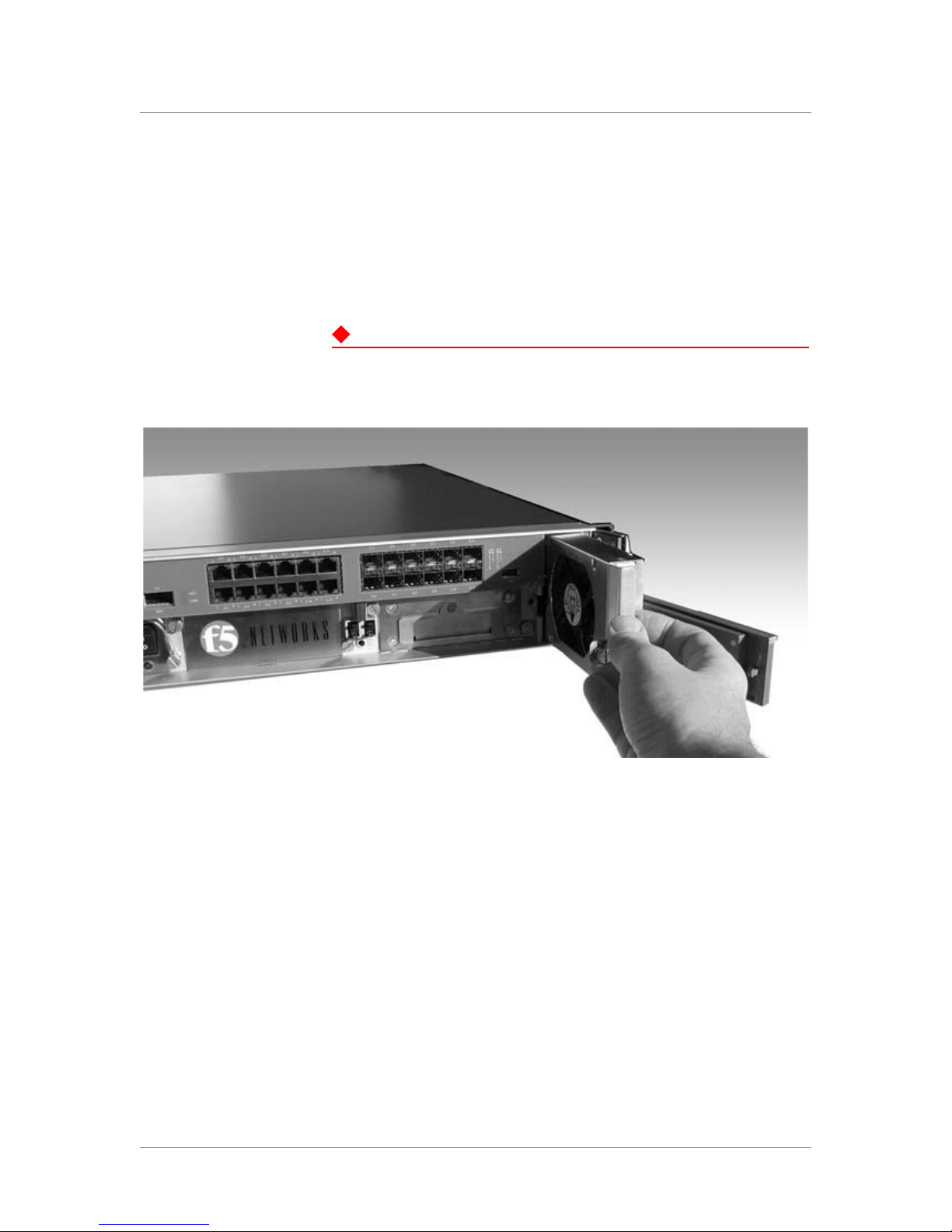
Figure 5.1 The removable fan and filter tray
5 - 2
Figure 5.1 shows an example of the fan and filter tray assembly partially
removed from the BIG-IP system. You can also replace the filter without
replacing the fan tray. This requires you to remove the fan tray, and take out
the old filter, and insert a new one.
To replace the filter only
1. Start by opening the front panel of the BIG-IP unit running in
standby mode.
2. The fan tray is held on the chassis by a knurled fastener. Loosen the
knurled fastener by turning it counter-clockwise.
3. Pull the old fan tray and filter out of the system.
4. Slide the old filter out of the fan tray filter slot. Slide the new filter
into the filter slot.
Page 53

5. Push the fan tray and filter back into the system.
The tray is automatically turned on when you slide the tray
completely into the chassis.
6. Tighten the knurled fastener into place by turning it clockwise.
7. Close the front panel of the unit.
Changing a power supply
The 8400/8800 series platforms have removable power supplies. You can
change or replace the power supply in the event of a power supply failure.
Replacing the power supply
You do not need special tools to replace the power supply. We recommend
that you perform the power supply replacement on the standby unit in a
redundant system after halting it and powering the system off. After you
install the power supply in the standby system, force the active system to fail
over and install the power supply replacement in the other unit of the
redundant system.
Maintaining the IP Application Switch Platform
To halt and power off the unit
1. On the LCD panel, press the X button, then use the arrow keys to
navigate to the System menu.
2. Press the Check button.
3. Navigate to the Halt menu.
4. Press the Check button.
5. Press the Check button again at the confirmation screen.
6. Wait 30 seconds.
7. Hold the X button for 4 seconds to power down the unit.
After you halt and power off the system, you can replace power supply.
To replace the power supply
1. Start by opening the front panel of the BIG-IP unit running in
standby mode.
2. The power supply is held on the chassis by two knurled fasteners.
Loosen the knurled fastener by turning it counter-clockwise.
3. Pull the old power supply out of the system.
Platform Guide: 8400 and 8800 5 - 3
Page 54
Chapter 5
4. Slide the new power supply into the power supply slot.
The power supply is connected to the system when you slide it
completely into the chassis.
5. Tighten the knurled fasteners into place by turning them clockwise.
6. Close the front panel of the unit.
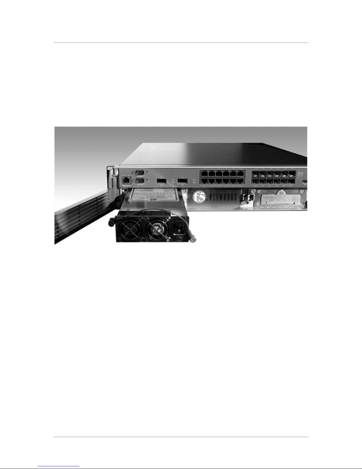
Figure 5.2 The power supply
Figure 5.2 shows an example of the power supply partially removed from
the BIG-IP system.
5 - 4
Page 55

Changing the drive tray
The 8400/8800 series platforms have a removable drive tray. You can
change or replace the drive tray as part of the routine maintenance of the
unit, or in the event of a drive failure.
We recommend that you back up your BIG-IP configuration files any time
you change them. In the event of a drive failure, you can replace the hard
drive tray, then you can reinstall the version of the BIG-IP software you
were running and use the configuration backup to restore the system to its
previous state.
Replacing the drive tray
You do not need special tools to replace the drive tray. We recommend that
you perform the drive tray replacement only on the standby unit in a
redundant system. After you install the drive tray in the standby system,
power up the system and force the active system to fail over. Install the
drive tray replacement in the other unit of the redundant system. You must
halt the system and shut it down before you replace the drive tray.
Maintaining the IP Application Switch Platform
To halt and power off the unit
1. On the LCD panel, press the X button, then use the arrow keys to
navigate to the System menu.
2. Press the Check button.
3. Navigate to the Halt menu.
4. Press the Check button.
5. Press the Check button again at the confirmation screen.
6. Wait 30 seconds.
7. Hold the X button for 4 seconds to power down the unit. After you
halt and power off the system, you can replace the drive tray.
To replace the drive tray
1. Open the front panel of the BIG-IP unit that you have halted and
powered off.
2. The drive tray is held on the chassis by two knurled fasteners.
Loosen the knurled fastener by turning it counter-clockwise.
3. Pull the old drive tray out of the system.
4. Slide the new drive tray into the drive tray slot.
The tray is automatically turned on when you slide the tray
completely into the chassis.
Platform Guide: 8400 and 8800 5 - 5
Page 56
Chapter 5
5. Tighten the knurled fasteners into place by turning them clockwise.
6. Close the front panel of the unit.
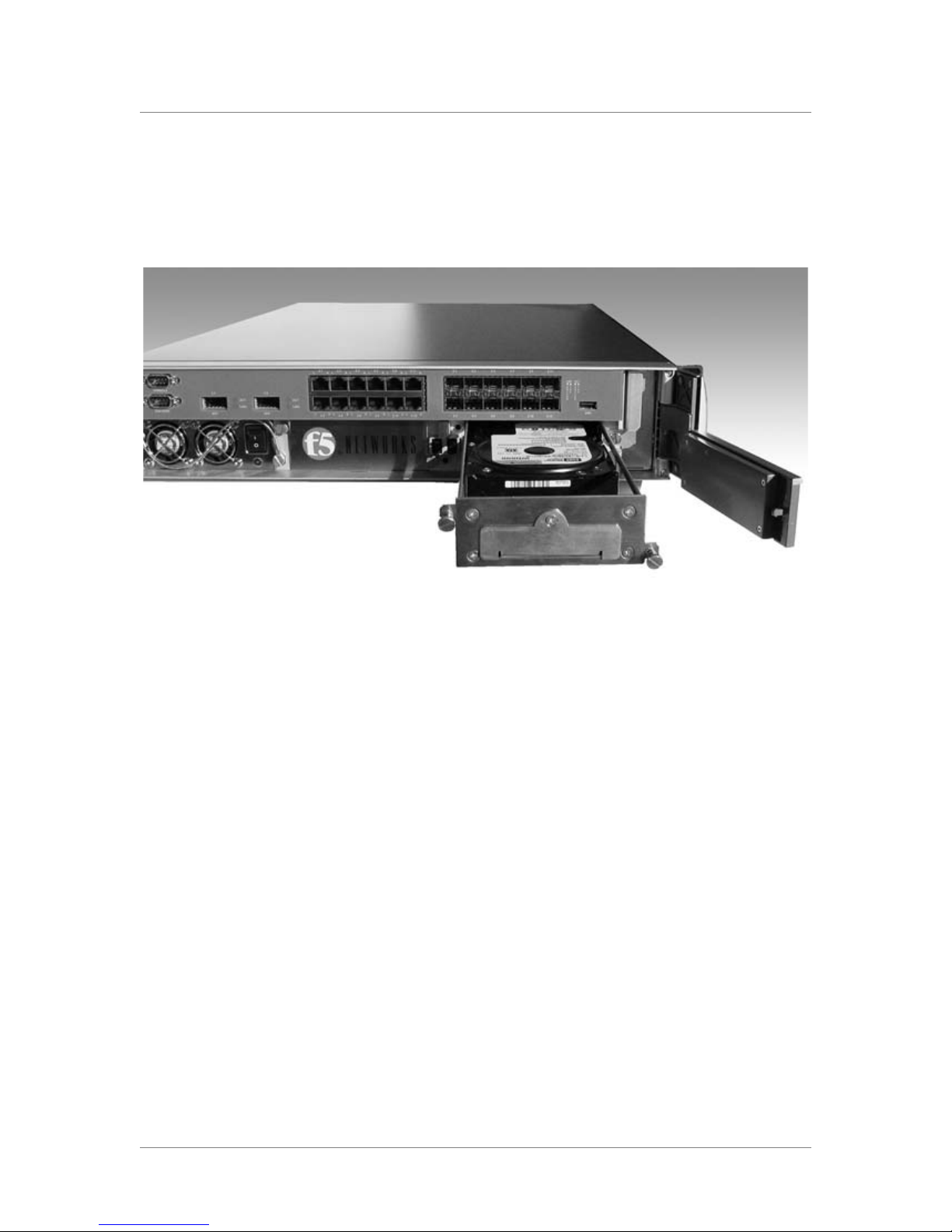
Figure 5.3 The removable drive tray
Figure 5.3 shows an example of the drive tray assembly partially removed
from the BIG-IP system.
5 - 6
Page 57

6
Working with Environmental Guidelines for
the IP Application Switch Platform
• Environmental requirements
Page 58

Page 59
Working with Environmental Guidelines for the IP Application Switch Platform
Environmental requirements
Before you install the IP Application Switch, review the following
guidelines to make sure that you are installing and using the IP Application
Switch in the appropriate environment.
General environmental guidelines
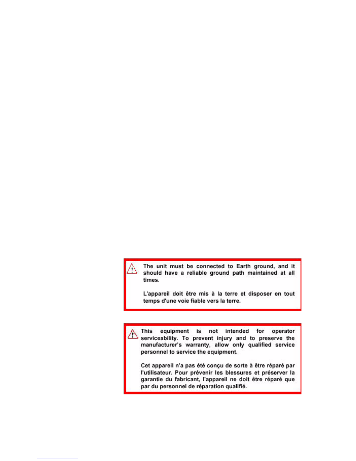
An IP Application Switch is an industrial network appliance, designed to be
mounted in a standard 19-inch rack. To ensure safe installation and
operation of the unit, be sure to adhere to these recommendations:
• Install the rack according to the manufacturer’s instructions, and check
the rack for stability before placing equipment in it.
• Build and position the rack so that once you install the IP Application
Switch, the power supply and the vents on both the left and right sides of
the unit remain unobstructed. The IP Application Switch must have
adequate ventilation around the unit at all times.
• Do not allow the air temperature in the room to exceed 40° C.
• Do not plug the unit into a branch circuit shared by more electronic
equipment than the circuit is designed to manage safely at one time.
• This product is sensitive to electrostatic discharge (ESD). We
recommend that when you install or maintain the unit, you use proper
ESD grounding procedures and equipment.
Platform Guide: 8400 and 8800 6 - 1
Page 60
Chapter 6
Guidelines for DC-powered equipment
A DC-powered installation must meet the following requirements:
• Install the unit using a 20 Amp external branch circuit protection device.
• For permanently connected equipment, incorporate a readily accessible
disconnect in the fixed wiring.
• Use only copper conductors.
6 - 2
Page 61

7
Understanding Platform Airflow
• Reviewing platform airflow information
Page 62

Page 63
Understanding Platform Airflow
Reviewing platform airflow information
When you install the 8400/8800 platform into a rack, it is important to
understand the unit’s airflow direction so that you can ensure proper
cooling.
Airflow for the 8400/8800 platform
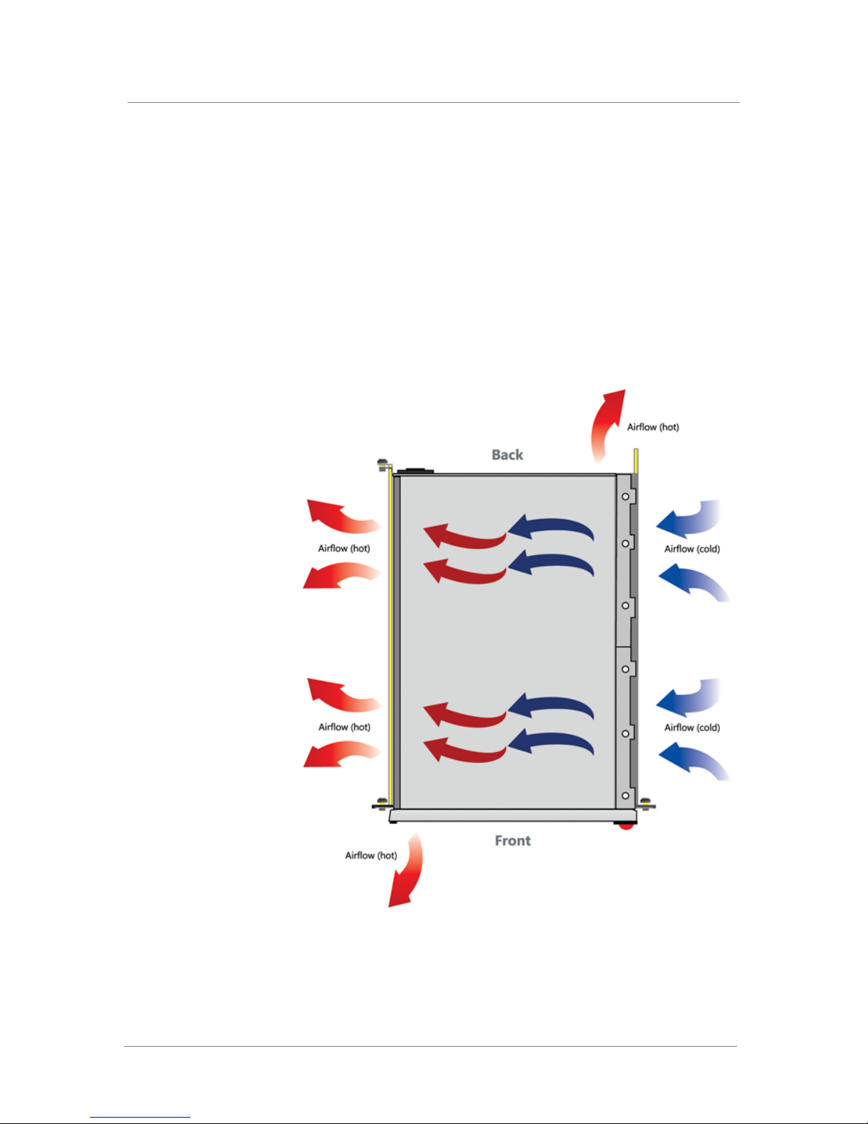
The 8400/8800 platform employs a positive pressure fan system, which
blows cold air in from the right side of the chassis and exhausts hot air out
the left and back sides of the chassis, as shown in Figure 7.1.
Platform Guide: 8400 and 8800 7 - 1
Figure 7.1 Airflow in 8400/8800 platform
Page 64

Chapter 7
7 - 2
Page 65

8
Reviewing Hardware Specifications
• Reviewing hardware specifications
• 8400 specifications
• 8800 specifications
• Additional acoustic, airflow, and altitude
specifications
Page 66

Page 67

Reviewing hardware specifications
The following section contains general information about the IP Application
Switch hardware platforms.
Item Specification
Reviewing Hardware Specifications
Server/Node Operating
System Compatibility
Internet/Intranet
Protocol Support
Administrative
Environment Support
Network Management
& Monitoring
Dynamic Content
Support
Device Redundancy Watchdog timer, fail-safe cable (primary & secondary)
Web Server
Application
Compatibility
Routing Protocols RIP, OSPF, and BGP with optional ZebOS Routing
Operating
Temperature
Load balancing of any TCP/IP OS, including Windows
NT, Windows 95, all UNIX platforms, and Mac/OS
All TCP services, UDP, SIP, and SSL; nearly all
IP-based protocols
DNS proxy, SMTP, SSH, SNMP, dynamic/static
network monitoring, scheduled batch job processing,
system status reports, and alarms event notification
Secure SSL browser-based interface, remote
encrypted login and file transfer using SSH monitor,
BIG-IP system network monitoring utilities and
additional contributed software; SNMP gets and traps
iControl API using CORBA & SOAP/XML
ASP (active server pages), VB (visual basic script),
ActiveX, JAVA,VRML, CGI, Cool Talk, Net Meeting,
Real Audio, Real Video, Netshow, Quick Time,
PointCast, any HTTP encapsulated data
Any IP-based web or application server
Modules
23° to 104° F (-5° to 40° C) per Telcordia GR-63-CORE
5.1.1 and 5.1.2
Platform Guide: 8400 and 8800 8 - 1
Relative Humidity 10 to 90% @ 40º C, per Telcordia GR-63-CORE 5.1.1
Safety Agency
Approval
Electromagnetic
Emissions
Certifications
Non-operational
specification
and 5.1.2
UL 60950 (UL1950-3)
CSA-C22.2 No. 60950-00 (Bi-national standard with UL
60950)
CB TEST CERTIFICATION TO IEC 950
EN 60950
EN55022 1998 Class A
EN55024 1998 Class A
FCC Part 15B Class A
VCCI Class A
Temperature -40º to 149º F (-40º to 65º C)
Humidity 10 to 95% at 40º non-condensing
Table 8.1 General IP Application Switch specifications
Page 68

Chapter 8
WARNING
Important
8400 specifications
The following specifications apply to only the 8400 IP Application Switch
platform.
Only optics modules provided by F5 Networks are supported in this
platform.
Item Specification
Dimensions 3.5"H x 19"W x 24"D (per unit) 2U industry standard
Weight 43 lbs. (single power), 46 lbs. (dual power) per unit
Processor Dual Opteron 2.6 GHz
Power Supply Optional redundant power supply
rack-mount chassis
ASIC Packet Velocity ASIC™ 10 (PVA 10)
Network Interfaces 12x10/100/1000 Copper ports
12x1000Base-X SFP Fiber ports
1000BASE-SX - 850nm (LC Connector, 6 modules
included)
1000BASE-LX - 1310nm (LC Connector, optional)
2x10 Gigabit XFP ports
10GBASE-SR - 850nm (LC Connector, optional)
1x10/100 Ethernet Management port
Hard Drive Capacity 512 MB flash with 80 Gigabyte hard drive
RAM 2 GB (expandable to 4 GB)
Power supply type 460W 90/240 +/- 10% VAC AUTO Switching
Input Voltage and
Current
Typical power
consumption
Heat generated 1365 BTU/hour
90-132 9A
80-264 4A
460W (AC)
Table 8.2 The 8400 IP Application Switch platform specification
8 - 2
Specifications are subject to change without notification.
Page 69

8800 specifications
WARNING
Important
The following specifications apply to only the 8800 IP Application Switch
platform.
Only optics modules provided by F5 Networks are supported in this
platform.
Item Specification
Dimensions 3.5"H x 19"W x 24"D (per unit) 2U industry standard
Weight 47 lbs. per unit
Processor Two Dual-Core Opteron 2.6 GHz
ASIC Packet Velocity ASIC™ 10 (PVA 10)
Reviewing Hardware Specifications
rack-mount chassis
Network Interfaces 12x10/100/1000 Copper ports
12x1000Base-X SFP Fiber ports
1000BASE-SX - 850nm (LC Connector, 6 modules
included)
1000BASE-LX - 1310nm (LC Connector, optional)
2x10 Gigabit XFP ports
10GBASE-SR - 850nm (LC Connector, optional)
1x10/100 Ethernet Management port
Hard Drive Capacity 512 MB flash with 80 Gigabyte hard drive
RAM 2 GB (expandable to 4 GB)
Power supply type Two 460W 90/240 +/- 10% VAC AUTO Switching
Input Voltage and
Current
Typical power
consumption
Heat generated 1778 BTU/hour
90-132 9A
80-264 4A
460W (AC)
Table 8.3 The 8800 IP Application Switch platform specification
Platform Guide: 8400 and 8800 8 - 3
Specifications are subject to change without notification.
Page 70

Chapter 8
Additional acoustic, airflow, and altitude
specifications
This section describes additional specifications such as acoustic levels,
airflow movement, and operational altitude for the BIG-IP 8400 and 8800
units.
Detail Units 8400 and 8800
Acoustic [1]
Front face db 65
Left face db 64
Right face db 68
Rear face db 65
Altitude [2]
Operational Feet 5905
Non-operational Feet 40000
Airflow
Entire chassis cfm 128.1
Table 8.4 Acoustic, altitude, and airflow specifications
[1] All measurements taken at 1 meter - A-weighting.
[2] Per BELCORE GR-63-CORE, section 4.1.3. 60 meters (197 feet) below
sea level to 1800 meters (5905 feet) above sea level.
8 - 4
Page 71

A
Installing an IP Application Switch Using an
Optional Rail-Mount Kit
• Installing the optional rail-mount kit
Page 72

Page 73
Installing an IP Application Switch Using an Optional Rail-Mount Kit
Installing the optional rail-mount kit
When you received your IP Application Switch, the unit included
rack-mount ears, suited for a standard type of mount. With rack-mount ears,
the unit is bolted directly to the rack.
As an option, you can use an alternative type of mount, called a rail mount,
which allows you to slide the unit in and out of the rack at will. To install
this rail-mount kit and install the unit into the rack, you need to perform the
following tasks:
• Remove some standard mount hardware from the unit
• Install the rail-mount kit hardware
• Install the unit into the rack
• Connect cables and other hardware
To perform these tasks, follow the instructions in the following sections.
Removing standard mount hardware from the unit
The first step in installing a rail-mount kit is to remove some
standard-mount hardware from the unit itself. Commonly referred to as
rack-mount ears, this hardware must be removed before you can install a
rail-mount kit.
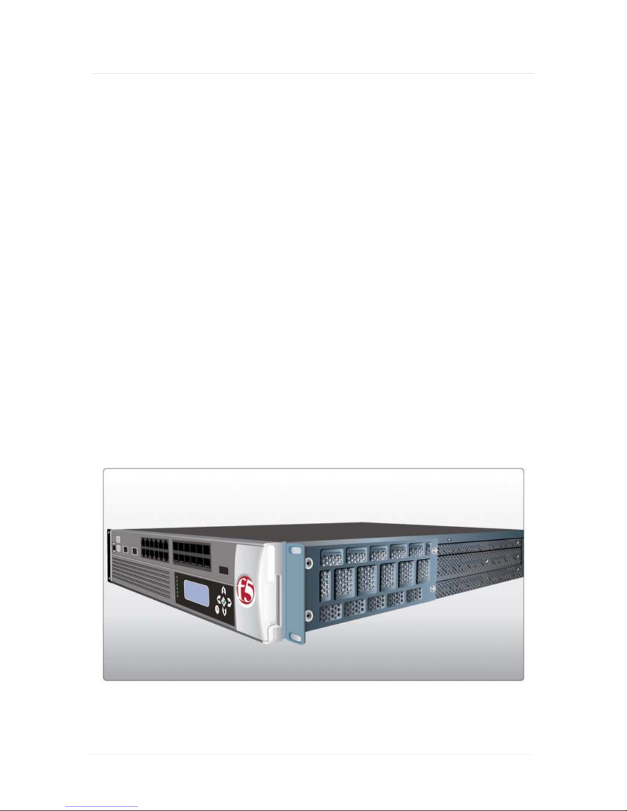
Figure A.1 shows one of the rack-mount ears on an IP Application Switch.
Figure A.1 A rack-mount ear on an IP Application Switch
Platform Guide: 8400 and 8800 A - 1
Page 74
Appendix A
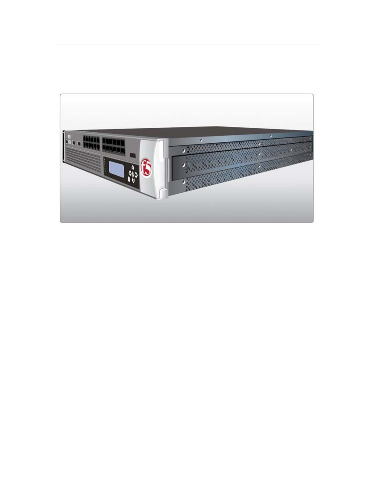
Figure A.2 shows the IP Application Switch after you have removed the
rack-mount ears.
Figure A.2 An IP Application Switch with a rack-mount ear removed
To remove the rack-mount ears from the unit
To remove the rack-mount ears from the unit, locate the four screws that
hold the rack-mount ears to the unit and unscrew them. You must do this for
both rack-mount ears, one on either side of the unit. Save the screws you
removed for the next procedure.
Installing the kit hardware
After you have removed the rack-mount ears from the unit, you must install
the rail-mount kit. The rail-mount kit consists of these parts:
• Two inner rails that you attach to either side of the unit. Once the kit is
installed, these inner rails slide into the outer rails that you install onto
the rack.
• Two stops that you attach to either side of the unit.
• Two outer rails that you attach to the rack. The inner rails that you install
on the sides of the unit will slide into these outer rails.
• Four optional brackets and screws for use on square-holed racks.
A - 2
Page 75
Installing an IP Application Switch Using an Optional Rail-Mount Kit
Attaching the inner rails and stops
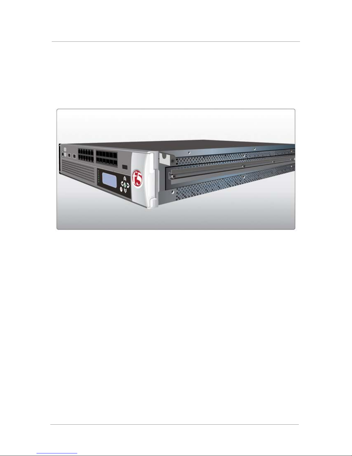
The first task in installing the optional rail-mount kit is to attach an inner rail
and a stop to each side of the unit. Figure A.3 shows the unit with an inner
rail and stop attached to one side.
Figure A.3 An inner rail with stop installed
To attach the inner rails and stops to the unit
1. Attach an inner rail to each side of the unit, as shown in Figure A.3,
using the four screws that you removed from each rack-mount ear.
Note that each side requires four screws.
2. Attach a stop to each side of the unit, near the front, as shown in
Figure A.3, using the screws provided in the kit.
Attaching the outer rails
Once you have installed the inner rails and stops to the unit, you can attach
the two outer rails to the rack. One outer rail is made specifically for the left
side of the rack, while the other outer rail is made specifically for the right
side of the rack.
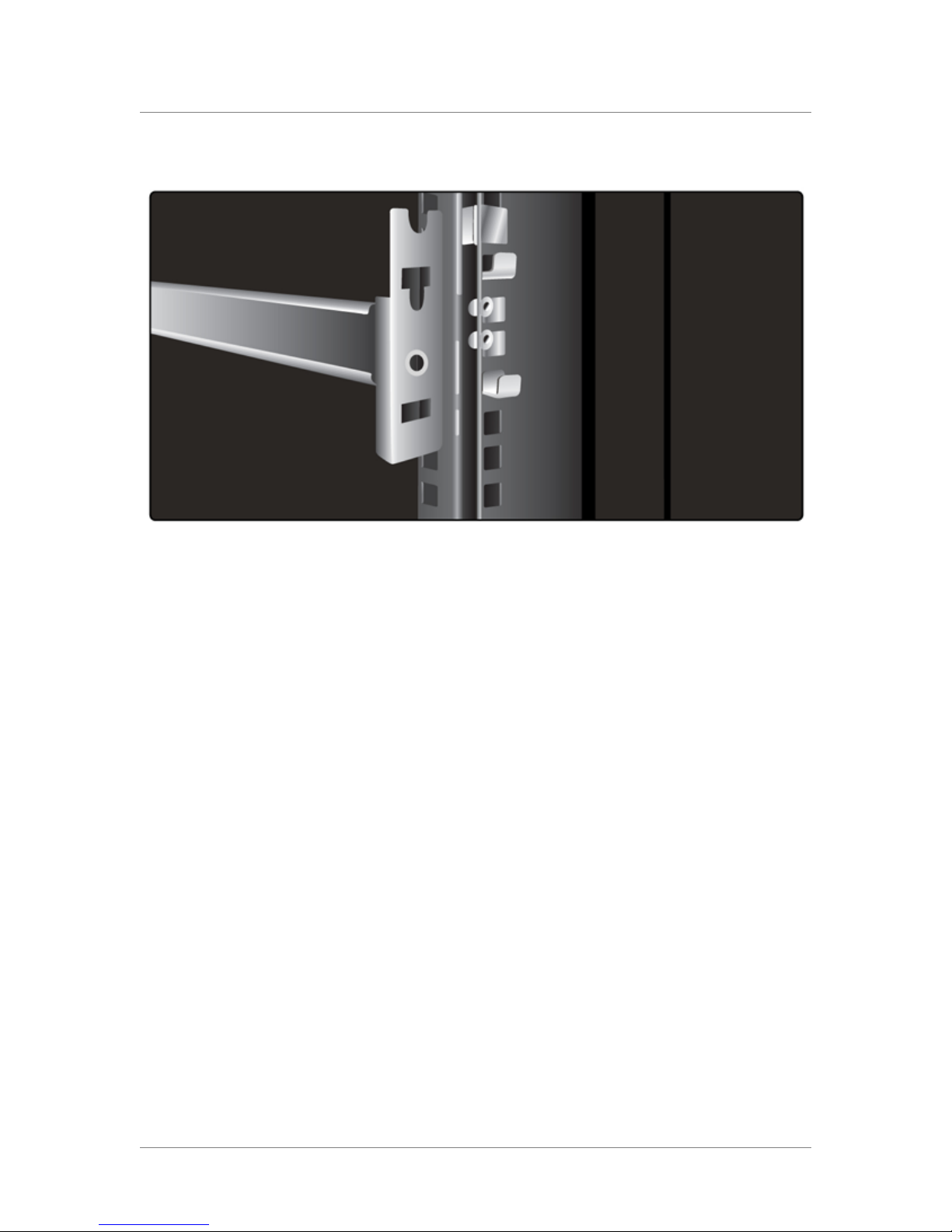
Each outer rail includes a bracket on the front, with a square hole and a
round hole. Figure A.4 shows a bracket with the square and the round holes.
Platform Guide: 8400 and 8800 A - 3
Page 76
Appendix A
Figure A.4 Outer rail and attached bracket
If the rack is a round-holed rack, use your own standard rack screws to
attach the rail and bracket directly to the rack.
If the rack is a square-holed rack, you must use the additional, separate
brackets included in the kit to attach the rail and bracket to the rack.
To attach the outer rails to the rack
1. Find the upper rail that corresponds to the side of the rack onto
which you are installing the rail.
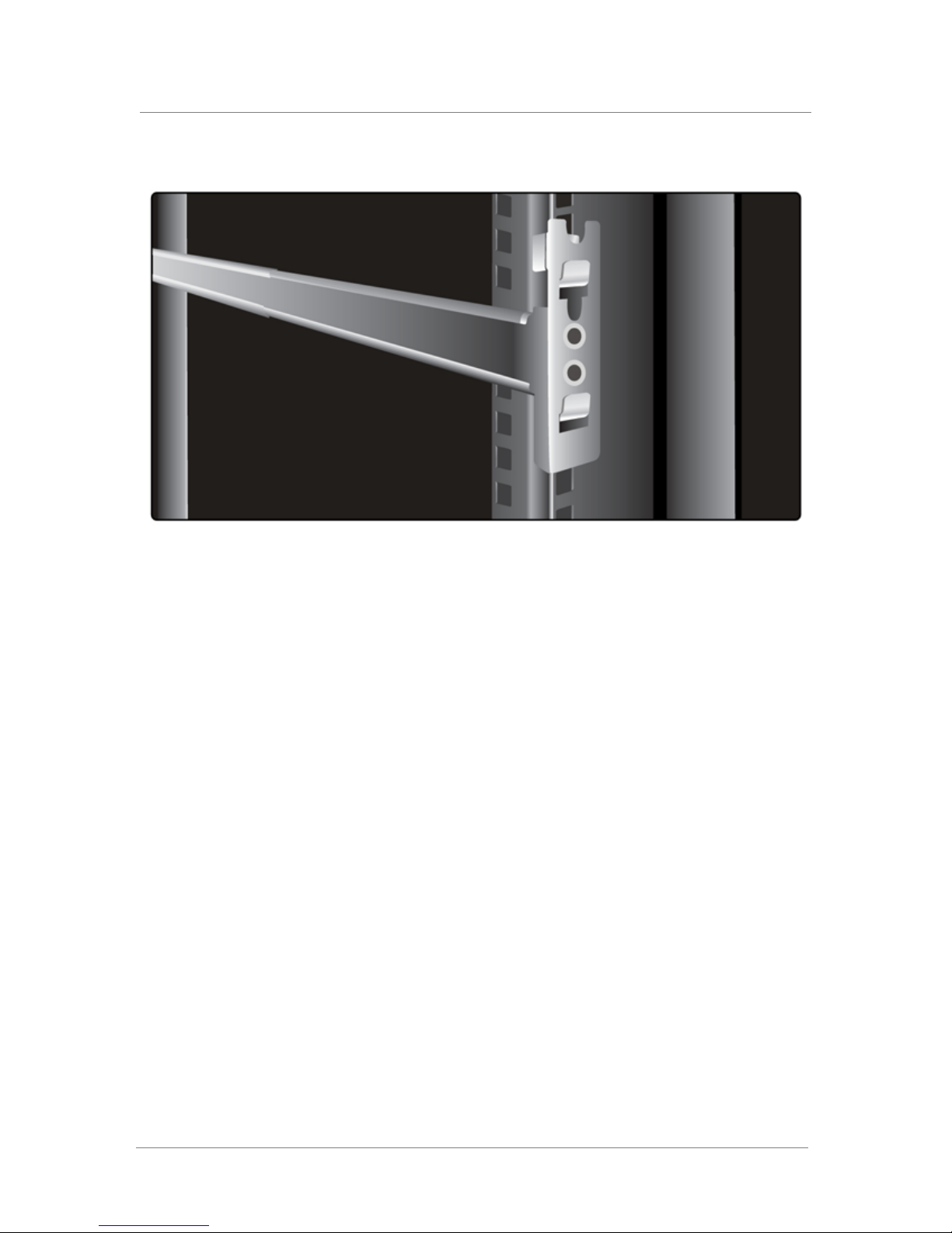
2. Attach the outer rail and bracket onto the rack as shown in Figure
A.5. Note the following:
a) If the rack is a round-holed rack, use standard rack screws.
b) If the rack is a square-holed rack, hang one of the separate
Figure A.5 shows a rack with an outer rail attached.
brackets provided with the kit onto each end of an outer rail, and
then use the screws provided to attach each rail onto the rack. To
accomplish this task, you will use a total of four separate brackets
(two per rail), and eight screws (two per bracket).
A - 4
Page 77
Installing an IP Application Switch Using an Optional Rail-Mount Kit
Figure A.5 Outer rail with attached bracket installed
Once the inner and outer rails are installed, you can easily install the unit
into the rack.
Installing the unit into a rail-mount rack
Use the following procedure to install the unit into the rail-mount rack.
To install the unit into the rack
1. Slide the unit into the rack, fitting the inner rails of the unit to the
outer rails of the rack.
2. On each side of the unit, screw a nut into the stop that you installed
on the unit.
Connecting cables and other hardware
After you have installed the unit into the rack, you need to connect certain
cables and other hardware. For more information, see Connecting the cables
and other hardware, on page 2-4.
Platform Guide: 8400 and 8800 A - 5
Page 78

Appendix A
A - 6
Page 79

B
Platform-Specific Hazardous Substance
Levels, for China
• 8400 platform
• 8800 platform
Page 80

Page 81
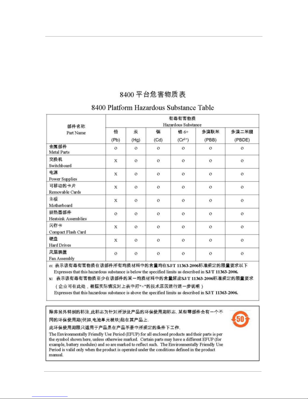
8400 platform
Platform-Specific Hazardous Substance Levels, for China
This table lists hazardous substances controlled by China, and shows how
the F5 Networks
®
8400 platform components conform to the standards.
Platform Guide: 8400 and 8800 B - 1
Page 82
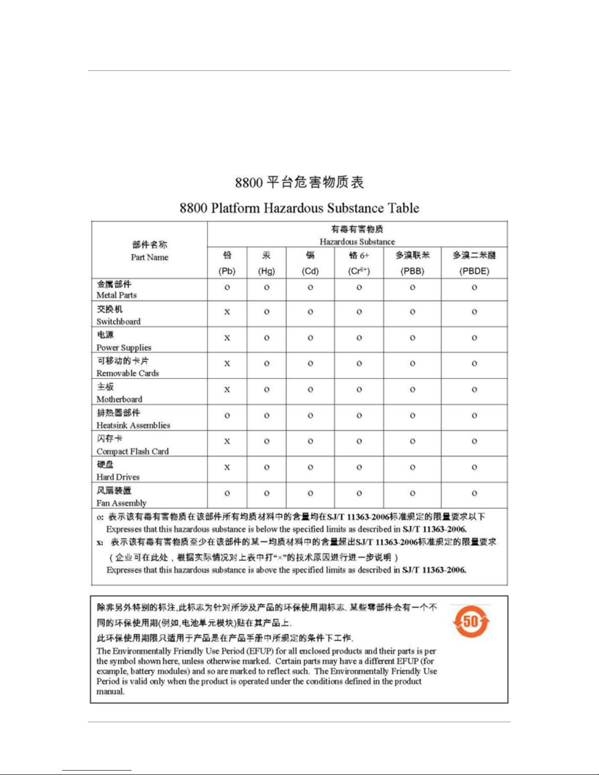
Appendix B
8800 platform
This table lists hazardous substances controlled by China, and shows how
the F5 Networks
®
8800 platform components conform to the standards.
B - 2
Page 83

Glossary
Page 84

Page 85

ASIC
bigpipe
BIOS
Configuration utility
DHCP
Glossary
An ASIC is an application specific integrated circuit.
The bigpipe utility provides command line access to the BIG-IP software.
BIOS stands for Basic Input/Output System. The BIOS is software that is
built-in to the computer and determines what the computer can do without
accessing programs from a disk.
The Configuration utility is the browser-based application that you use to
configure the software.
DHCP stands for Dynamic Host Configuration Protocol. It is a protocol
used to assign dynamic IP addresses to network devices. When using
DHCP, a network device can have a different IP address each time it
connects to the network.
DNS
FRU
LCD
NIC
PXE
DNS stands for Domain Name System. It is a service that translates domain
names into IP addresses. For example, the domain name
www.siterequest.com might translate to 101.102.103.104.
An FRU is a field replaceable unit. You can order FRUs to replace certain
parts of the unit including the fan tray, fan filter, drive tray, and power
supply.
LCD stands for liquid crystal display. An LCD panel is available on the
front of the 8400 platforms. You can use the LCD and its associated controls
to configure the management port on the unit and view basic statistics.
NIC stands for Network Interface Card. It is an expansion board used to
connect a computer to a network.
PXE stands for Pre-Boot Execution Environment, a network boot method. It
allows you to boot a computer from a server on a network before you boot
the operating system on the local hard drive.
Platform Guide: 8400 and 8800 Glossary - 1
Page 86

Glossary
SCCP
SFP GBIC
SSH
SSL
subnetwork
SCCP stands for the switch card control processor. A processor that
provides control over the hardware in the unit for lights-out management.
SFP GBIC stands for small-form factor pluggable (SFP) gigabit interface
converter (GBIC).
SSH is a protocol for secure remote login and other secure network services
over a non-secure network.
SSL stands for Secure Sockets Layer. It is a protocol that uses a public key
to encrypt data transmitted through the Internet over an SSL connection.
URLs using an SSL connection start with HTTPS: instead of HTTP:.
The portion of a network that shares a common address component. For
instance, on TCP/IP networks, a subnetwork is all devices whose IP
addresses have the same prefix segment.
Telnet
terminal emulator
virtual server
Telnet is a terminal emulation program for TCP/IP networks. Telnet runs on
your computer and connects it to a server on the network. It then allows you
to enter commands as though you were directly connected to the server
console.
A terminal emulator is a program that mimics a terminal.
Virtual servers are a specific combination of virtual address and virtual port,
associated with a content site that is managed by a BIG-IP system or other
type of host server.
Glossary - 2
Page 87

Index
Page 88

Page 89

1U spacing 2-1
8400 platform
and green solid Activity LED 4-4
and unlit Activity LED 4-2
Index
D
DC power 2-2, 2-5
DC-powered equipment guidelines 6-2
drive tray replacement 5-5
duplex mode 4-6
A
acceleration
for hardware 4-7
for Layer 4 4-7
acoustic specifications 8-4
Activity LED 4-1
when green intermittent 4-4
when solid green 4-4
when yellow intermittent 4-3
additional information, finding 1-7
airflow
and direction 7-1
See also platform airflow.
airflow specifications 8-4
Alarm LED 4-1
alerts
and LCD 3-3
clearing 3-3
altitude specifications 8-4
ASIC. See Packet Velocity ASIC 10.
Ask F5 natural language engine 1-10
B
BIG-IP Quick Start Instructions 1-7
C
cable, fail-over 1-2, 2-5
chassis
and airflow 7-1
Check button
and clearing alerts 3-3
for power on 3-2
China material content listing B-1, B-2
clear alert operation 3-3
command line syntax table 1-9
command syntax, identifying 1-9
components provided with IP Application Switch 1-2
Configuration utility
about online help 1-10
about the Welcome screen 1-10
Configuration Worksheet 1-7
cooling system, for platform 7-1
copper interfaces 1-1
E
electrostatic discharge (ESD) 2-2, 6-1
environmental guidelines 6-1
See also hazardous substance restrictions.
Ethernet hub requirements 1-3
F
fail-over cable 1-2, 2-5
fan system 7-1
fan tray and filter replacement 5-1
fiber interfaces
and LC connector type 1-1
fiber module types 8-2, 8-3
filter only replacement 5-2
G
Gigabit Ethernet 1-3
grounding, providing 2-2
H
halt operation 3-2
hardware
and appearance 1-4
and environmental guidelines 6-1
for DC-powered equipment 6-2
hardware acceleration 4-7
hardware installation
connecting cables 2-4
in rack 2-1
installing in rack 2-1
planning 2-1
hardware requirements
for components 1-2
for peripherals 1-3
hardware specifications
additional IP Application Switch 8-1
for 8400 8-2
for 8800 8-3
hazardous substance restrictions
for China B-1, B-2
help, online 1-10
Hold mode 3-2
hot-swap components
and fan tray 5-1
and filter 5-2
hubs 1-3
Platform Guide: 8400 and 8800 Index - 1
Page 90

Index
I
indicator LED 4-1
and actions 4-1
and functions 4-1
and types 4-1
configuring 4-3
displaying node status 4-3
for alert conditions 4-2
for special conditions 4-3
indicator lights 1-4
Information menu 3-1, 3-4
installation. See rack installation.
interface media type 4-6
interface mode 4-6
interface settings
displaying 4-5
interface status
displaying 4-5
intermittent Activity LED 4-3, 4-4
IP Application Switch
installing A-5
IP Application Switch platform
and components provided 1-2
installing 2-1
reviewing 1-4
L
LCD
and alerts 3-3
for information menu 3-4
for options menu 3-7
for screens menu 3-6
for system menu 3-5
LCD menus
accessing 3-4
introducing 3-4
navigating 3-4
LCD panel
configuring 3-2
LED. See indicator LED.
liquid crystal display, See LCD. 3-1
M
MAC addresses screen 3-6
management interface 2-5
media types
and attributes 4-6
setting 4-6
Menu mode 3-2, 3-4
menus on LCD panel 3-4
N
Network and System Management Guide 1-7
new terms, identifying 1-8
O
online help 1-10
optic modules 8-2, 8-3
Options menu 3-1, 3-7
P
Packet Velocity ASIC 10 4-7
panel. See LCD panel.
platform
cooling system 7-1
platform airflow
for 8400/8800 platform 7-1
See also airflow.
platform orientation 2-3
ports 1-4, 1-5
positive pressure fan system 7-1
power cable 2-5
power down operation 3-3, 5-3, 5-5
Power LED 4-1
power supply replacement 5-3
power up operation 3-2
product information, finding 1-10
R
rack installation
connecting components 2-2
rack mounting 2-1, 6-1
rack-mount ears
defined 2-1, A-1
removing A-2
rack-mounting hardware 1-2
rack-mounting screws 2-2
rail mount
and cables 2-4
defined A-1
introducing 2-1
rail-mount kit, installing A-2
rails
installing A-3
reboot unit operation 3-3
redundant systems
and fail-over cable 1-2
references
identifying 1-8
to commands 1-8
remote administration 1-3
replacement
of drive tray 5-5
of fan tray 5-1
of filter 5-2
of power supply 5-3
Rotate mode 3-2
round-holed racks A-3
Index - 2
Page 91

S
safe installation recommendations 6-1
Screens menu 3-1, 3-6
serial terminal
and hardware installation 1-3, 2-4
solid Status LED 4-4
solution examples 1-8
specifications, hardware
for 8400 8-2, 8-3
for China, material content B-1, B-2
square-holed racks A-3
standard operating state. See indicator LED.
Status LED 4-1
when solid green 4-4
when solid yellow 4-4
stylistic conventions 1-8
switches 1-3
syntax. See command syntax, identifying.
system airflow
See airflow.
System menu 3-1, 3-5
Index
T
technical documentation, finding 1-10
technical support web site 1-10
U
USB port
and supported CD drives 1-3
V
ventilation 6-1, 7-1
W
warnings, environmental 6-1
See also China material content listing.
Welcome screen
about 1-10
X
X button
on LCD panel 3-2
Platform Guide: 8400 and 8800 Index - 3
 Loading...