

ez WheelS EZRTHW1 Users manual
Operating Manual
autonomous wheels ezW10 and
ezW300
tiller head ezRTH
wireless versions
Revision B – May 2014


Index
1. Characteristics of the ez-Wheel product 4
2. Installation of the ez-Wheel product 5
□ Positioning/direction of operation 5
□ Mounting of the tiller head 5
□ Mounting of the wheel on the application 5
3. Use of the ez-Wheel product 7
□ Starting up for the first time 7
□ Use 7
□ Charging the wheel 8
□ Charging of the tiller head batteries 9
□ Versions with tyres: Changing a tyre 9
□ Versions with solid tyres 10
4. Precautions for use 10
□ Wheel maintenance 10
□ Prolonged shutdown 11
□ Precautions for use relative to the wheel 11
□ Precautions for use relative to the tiller head 11
□ Safety rules in relation to the batteries 11
□ Incorrect use 11
5. Customer Department contact 11
6. Troubleshooting 12
□ Display 12
□ Changing a tyre 12
□ Wheel malfunctioning 12
□ Tiller head malfunction 13
□ System reset procedure 13
7. Product end-of-life 13
8. Compliance with the limits for digital device 13
9. Radiation exposure limits 14
□ The wheel 14
□ The tiller head 14
Display 15
Declaration of incorporation 16
Declaration of CE conformity 16
Do not use ez-Wheel products for other purposes or in other conditions than those mentioned in the
technical documentation.
Read and make sure you have understood the manual before using ez-Wheel products.
Observe all the warnings and usage instructions in this manual.
Keep this manual for reference throughout the life of the product.
In the event of loss, you can obtain a copy of this manual from the ez-Wheel Customer Department
If the product is transferred to another owner, make sure that the manual is transferred as well.
The characteristics, descriptions, and illustrations in this document are applicable at the date of
publication. ez-Wheel reserves the right to make any modifications and revisions to this document. Product
users obtain their own information on these modifications.
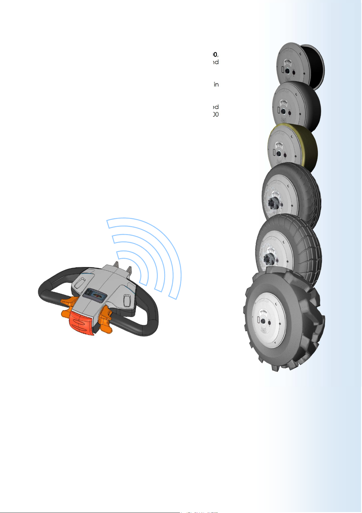
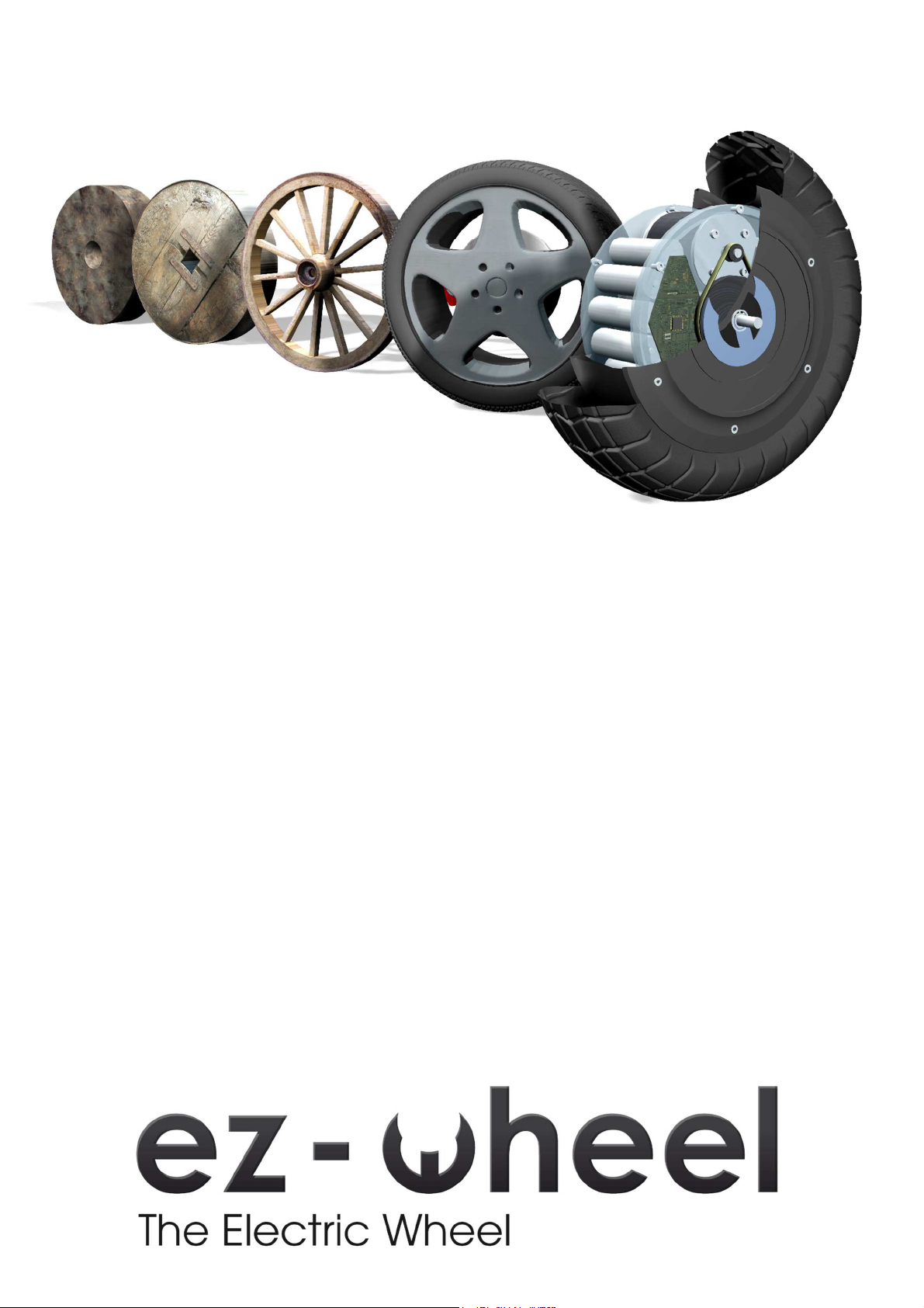
1. Characteristics of the ez-Wheel product
The range of autonomous wheels, ezW10 and ezW300,
enables powerful electric drive to be installed quickly and
easily.
ezW10 and ezW300 wheels are controlled by the interface in
the tiller head ezRTH via a wireless communication system.
This operating manual contains the instructions to be followed
for installation, use and maintenance of ezW10 and ezW300
wheels and the ezRTH tiller head
Page 4 User's Manual – Revision B – May 2014
2. Installation of the ez-Wheel product
All mechanical drawings that could serve for the installation of
ez-Wheel products are available on request.
All the accessories mentioned are available in the ez-Wheel
catalogue.
The wheels and the tiller heads are designed to work together
according to the configuration described in the configuration
sheet delivered with the equipment.
□ Positioning/direction of operation
• Refer to the configuration sheet.
• Take the tiller head with the serial number mentioned on
the configuration sheet.
• Identify the serial numbers of the wheels given on the
configuration sheet.
• Prepare and position the corresponding wheels, as shown
on the configuration sheet
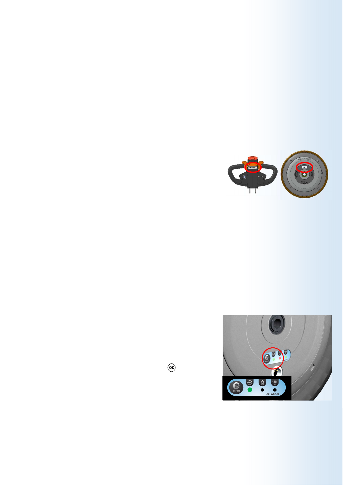
□ Mounting of the tiller head
• The tiller head must be held by the plate situated on the
back of the box.
• Fix the tiller head to the application in such a way as to
ensure that it is intuitive and ergonomic for the user to
handle it.
All mechanical drawings that could serve for the installation of
the tiller head are available on request.
□ Mounting of the wheel on the application
• Check that the tiller head is switched off: All lights are off.
• Inspect the general condition of the wheel and check for
damage.
• Check the condition of the wheel: Press the ON/OFF zone
on the wheel label and check that the light is green.
Page 5 User's Manual – Revision B – May 2014
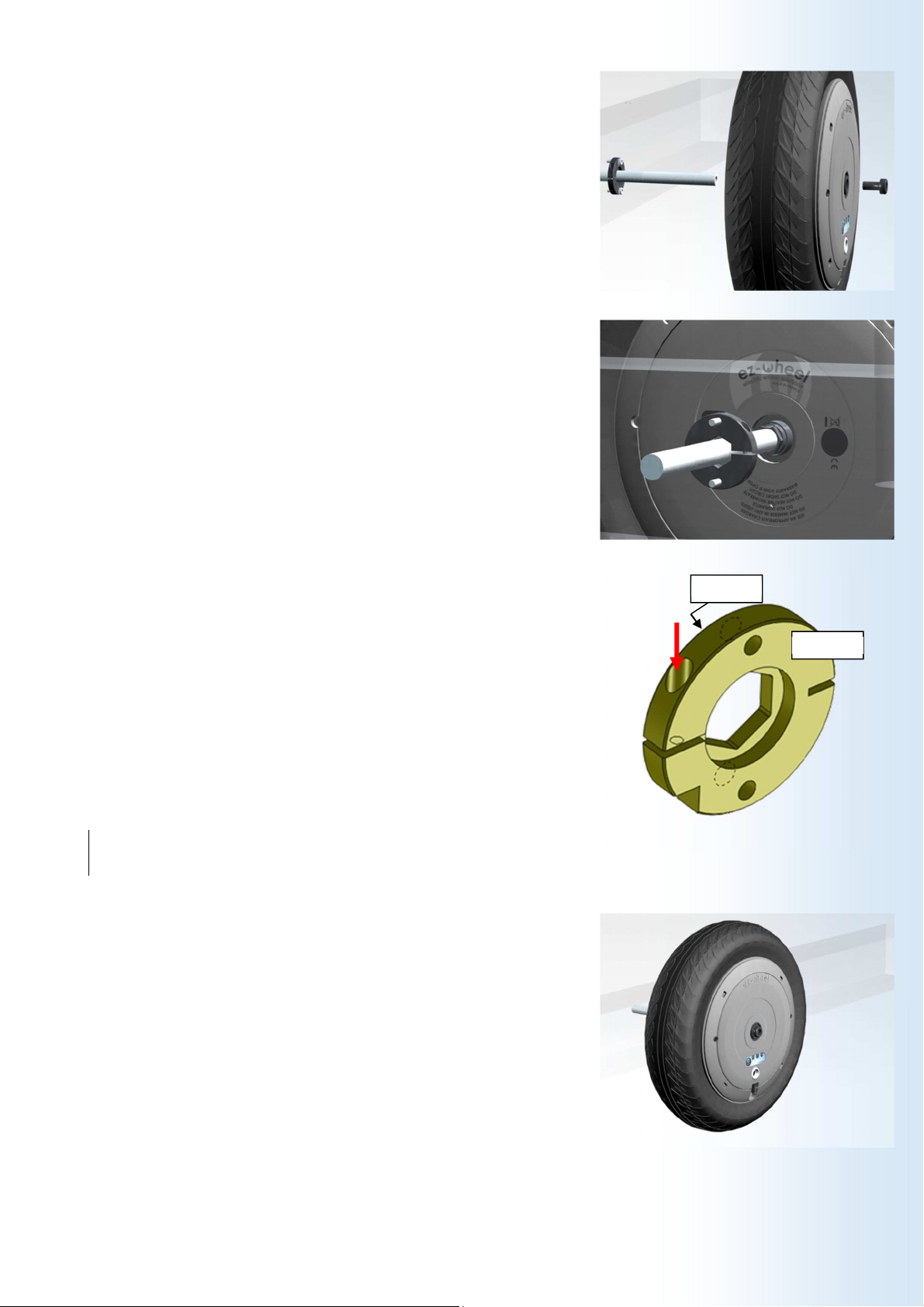
• Check that the application on which the wheel is going to
be mounted has a spindle with a diameter of 16 mm, of
which the length corresponds to the thickness of the wheel,
for each wheel.
• Check the presence of a hexagon anti-rotation zone (XC
18 steel or equivalent hardness).
• Position the wheel on the spindle and make sure that the
hexagon zone of the wheel is correctly inserted in that of
the application.
• The optional ezMAR anti-rotation washer accessory can be
used.
Remove the M3 screw from the ezMAR washer with a 2.5
mm Allen key.
- Position the hexagon zone of the ezMAR clamp on the
wheel spindle. It is possible to use a mallet for this operation
but the wheel spindle must not be damaged in any
circumstances. Face A of the clamp should be against the
wheel.
- Tighten the M3 side screw with an Allen key to ensure that
the clamp is locked around the hexagon zone.
CHC M3x12 SCREW
2.5 mm Allen key
Mallet
• Lock the wheel to the spindle with a screw on the side
opposite the hexagon zone (or both sides of the spindle if
the application is fitted with a fork or a yoke)
• Check the holding of the wheel before putting the tiller
head into operation.
• Repeat this operation for each wheel if the system has
several wheels.
Face B
Face A
Page 6 User's Manual – Revision B – May 2014
 Loading...