

Page 1
www.ezurio.com
802.11b/g Wireless LAN – TCP/IP (BISM II Pin Compatible)
Part Number: WISMC01BI
1. General Description
EZURiO’s Wireless LAN Module is a fully integrated and qualified solution for adding 802.11
functionality to embedded products. Unlike other modules it implements a complete wireless system,
including antenna, 802.11b/g radio, wireless network drivers, TCP/IP stack, security (WEP, WPA2,
SSL), a web-server, UART, GPIOs, 10 bit ADCs, plus an interpreter with a wireless language and user
accessible flash storage for program scripts. It is ideal for integration within M2M applications. It can
also be used for remote monitoring with the addition of just a sensor and battery/power supply.
The optimised RF section provides an output of up to +17dBm using the integrated ceramic antenna.
Coupled with a receive sensitivity of -84dBm, a range of 100 metres is achievable. A separate u.fl
connector is fitted to the module which allows a second antenna to be connected to take advantage of
antenna diversity. For most applications the internal antenna is sufficient. It provides a largely
omnidirectional distribution and is highly resistant to detuning, allowing the module to be fitted in a
wide variety of situations with no degradation of the radio performance.
An integrated ARM processor runs all of the wireless drivers and protocol stack. It includes a web
server that can be used to interrogate the variety of interfaces within module. The processor runs
EZURiO’s high efficiency embedded interpreter, which gives the module its amazing power. Users can
write simple scripts for the interpreter, which supports the BASIC language, as well as an extensive
range of commands to control the wireless connection. Scripts can be auto-run at power up to turn
the module into a self-contained wireless application processor. A low cost development system is
available for fast product evaluation and development.
The module contains an industry standard RS-232 UART for connection to a host processor,
peripheral device or sensor. This is capable of baud rates up to 921,600 bps for high speed data
transfer. Nine General Purpose I/O lines and two 10 bit analogue input lines are also provided. These
can be configured using scripts to provide control or monitoring of simple devices such as switches or
LEDs without a requirement for any external processing. Both the GPIO and ADC lines can be
accessed either via the wired host UART connection, or remotely over the Wireless LAN connection.
For battery and low power operation, support is provided for IEEE powersave modes, which can
reduce the current consumption to less than 10mA. This makes the module ideal for battery powered
sensor applications.
The Wireless LAN module is supplied in a small pcb form factor (22.0mm x 34.0mm x 7.6mm), that
connects to a main pcb using a 40 way Hirose connector. It is pin compatible with the EZURiO
Bluetooth Intelligent Serial Module BISMII. The Wireless LAN module is Lead-free and is RoHS
compliant and supports an industrial temperature range of -40°C to +85°C.
1.1 Applications
• POS Equipment
• Medical Equipment
• Telematics
• Industrial Automation
• Automotive Applications
• Battery Powered Sensors
© 2005-2006 Ezurio Ltd Data Sheet
1
Page 2

2. Features
Feature Implementation
Wireless LAN Transmission Complete stand alone device with on board flash
Drivers Embedded 802.11b/g
Protocol TCP/IP IPv4 and DHCP
Range 100 metres typical
Frequency 2.4 – 2.484 GHz
11 channels – USA
Channels
Max Transmit Power
Receive Sensitivity -84dBm @ 2Mbps
13 channels – Europe (excl France)
14 channels – Japan
4 channels – France
+15 dBm @ antenna connector.
+17dBm from integrated antenna
+10 dBm limit for France and Hungary
Interface UART Interface
Programmable Real-time scripting engine
Data Transfer rate Up to 2 Mbps (determined by UART)
Serial Interface
Serial parameters Default 115200,n,8,1.
Configurable from 9,600 bps. Default 921,600 bps
Security WEP encryption 64 and 128 bit options, WPA, WPA2, SSL
Network support Access Point
I/O 2 x 10bit ADC’s
9 GPIO
Current consumption
Temperature Range
Supply Voltage 3.3V – 5.0V
Interface Levels 3.0V Logic
Connection Option: 40 way BISM II pin compatible Hirose connector
Lead free Lead-free and RoHS compliant
Warranty 2 Years
RS-232 bi-directional for commands and data.
16550 compatible. DTR, DSR, DCD, RI, RTS, CTS
Less than 250mA (this depends on the data rate – 250mA is at
115kbaud) during data transfer with a configurable low power mode
-40°C to +85°C (requires operation in powersave modes)
-30°C to +60°C (continuous operation)
The features described within this data sheet are those targeted for the first production
release of firmware. Note that not all of these features may be available within individual
releases of the Engineering Sample firmware. Check with the firmware release notes to
determine the supported functionality.
© 2005-2006 Ezurio Ltd Data Sheet
1
Page 3
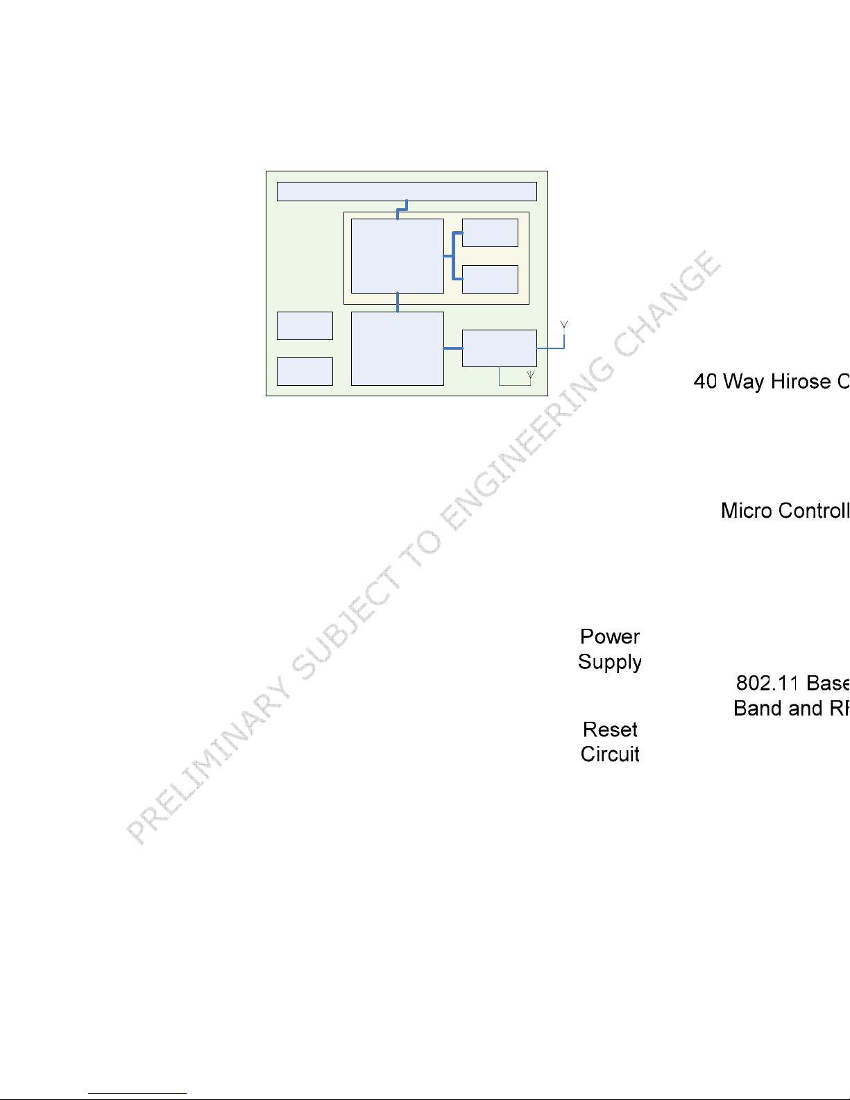
2.1 Block Diagram
The module will have 40 way Hirose connector which will have a compatible pin out to the
EZURiO Bluetooth Intelligent Serial Module, BISM II Hirose connector.
3. Mechanical
Figure 1 Wireless LAN Module Dimensional outline
© 2005-2006 Ezurio Ltd Data Sheet
2
Page 4
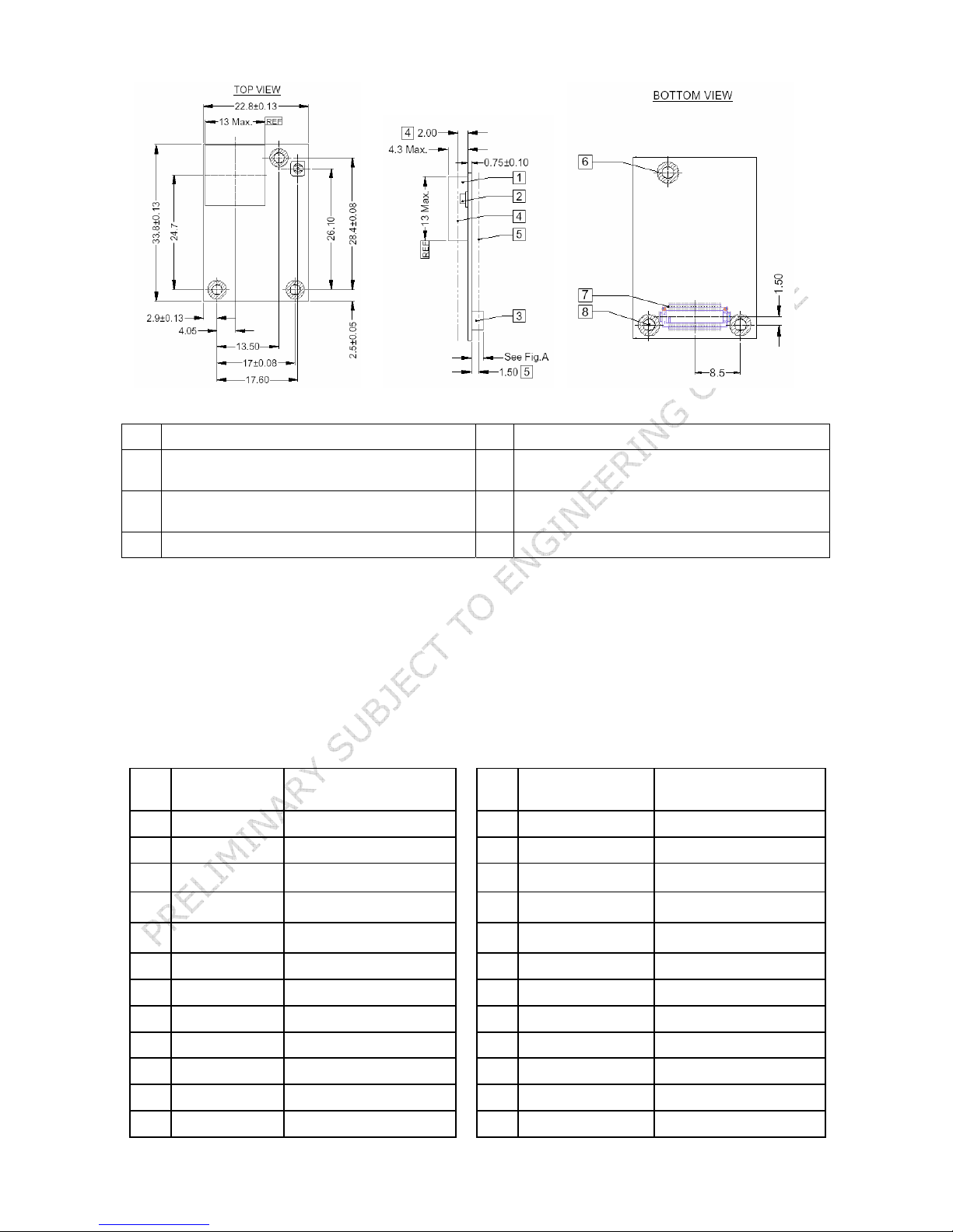
1 RF antenna 2 Optional RF connector (Hirose U.FL-R-SMT)
3 Board to board connector (Hirose connector) 4 2MM maximum top side component height
(excluding antenna)
5 1.5MM maximum bottom side component
height
7 40 way connector 8 2.2 +/- 0.075 fixing holes X 3
6 3.8 max. pcb clearance for fixings body (top
and bottom)
3.1 40 way Hirose Pin Descriptions
The Hirose DF12C board-to-board connector on the module is a 40-pin double-row receptacle.
The table below defines the pin functions. Note that this pin-out is as viewed from the underside of the
Module.
Pin
Signal Description Pin
No.
1 ADC 0 1.8v Max 2 GPIO1 I/O for Host.
3 ADC 1 1.8v Max 4 GPIO2 I/O for Host
WLAN_ACTIVE
5
7 N/C
9 N/C
11 GND 12 GPIO3/UART_DTR I/O for Host
13 RESET Reset I/P * 14 GPIO4 I/O for Host
15 GND 16 GPIO5 I/O for Host
17 N/C Not used 18 GND
19 UART_CTS Clear to Send I/P 20 IRQ0 Input
21 UART_TX Transmit Data O/P 22 WAKEUP Not used
23 UART_RTS Request to Send O/P 24 BT_PRIORITY Input
Output
6 UART_RI ‘Ring’ Input or Output
8 UART_DCD Input or Output
10 UART_DSR Input
Signal Description
No.
© 2005-2006 Ezurio Ltd Data Sheet
3
Page 5

25 UART_RX Receive Data I/P 26 N/C Not used
27 VCC_3V 3.0V Monitor 28 VCC_5v Input
29 VCC_5V Input 30 GND
31 VCC_5V Input 32 N/C
33 GPIO6 I/O for Host 34 N/C
35 GPIO7 ** I/O for Host 36 GND
37 GPIO8 ** I/O for Host 38 GND
39 GPIO9 I/O for Host 40 BT_STATE
Notes:
* The reset circuitry within the module incorporates a brown-out detector. The reset line has a fixed
10kOhm pull down resistor to ground.
GPIO lines can be configured through software to be either inputs or outputs. At reset, all GPIO lines
are configured as inputs.
UART_RX, UART_TX, UART_CTS, UART_RTS, UART_RI, UART_DCD and UART_DSR are all 3.0v level
logic. For example, when RX and TX are idle they will be sitting at 3.0V. For handshaking pins CTS,
RTS, RI, DCD, DSR, 0v is treated as an assertion.
Pin 8 (UART_DCD) is active low. It is normally 3.0v. When a connection is live this pin is low. This
means that when this pin is converted to RS232 voltage levels it will have the correct voltage level for
assertion.
Pin 10 (UART_DSR) is an input, with active low logic. It should be connected to the DTR output of the
host.
Pin 27 (VCC_3V monitor) may only be used for monitoring purposes. It must not be used as a current
source.
ADC inputs (pins 1 and 3) are read using UW script functions.
3.2 Electrical Specifications
3.2.1 Absolute Maximum ratings
Absolute maximum ratings for supply voltage and voltages on digital and analogue pins of the Module
are listed below; exceeding these values will cause permanent damage.
Parameter Min Max Unit
Peak current of power supply 550 mA
Voltage at digital pins -0.3 3.3 V
Voltage at POWER pin 3.3 5 V
3.2.2 Recommended Operating Parameters
3.2.2.1 Power Supply
Signal Name Pin No I/O Voltage level Comments
Vcc 29 I 3.3V to 5.0V I
GND 11, 15, 18,
30, 36, 38
© 2005-2006 Ezurio Ltd Data Sheet
= 250mA
typ
6 Ground terminals to be attached
in parallel
4
Page 6

Signal Name Pin No I/O Voltage level Comments
VCC_3V0 27 O 3.0V typical For monitoring only. No current
source
3.2.2.2 RS-232 Interface
Signal Name Pin No I/O Signal level Comments
UART_TX 21 O
UART_RX 25 I
UART_CTS 19 I
UART_RTS 23 O
UART_DSR 10 I VILmax=0.8V
UART_DTR 12 O
UART_RI 6 I or O
UART_DCD 8 I or O
VOLmax=0.2V
min=2.8V
V
OH
VILmax=0.8V
min=2.1V
V
IH
max=3.3V
V
IH
VILmax=0.8V
min=2.1V
V
IH
max=3.3V
V
IH
max=0.2V
V
OL
min=2.8V
V
OH
min=2.1V
V
IH
max=3.3V
V
IH
VOLmax=0.2V
min=2.8V
V
OH
O/P : VOLmax=0.2V
V
I/P : V
V
V
min=2.8V
OH
max=0.8V
IL
min=2.1V
IH
max=3.3V
IH
O/P : VOLmax=0.2V
V
I/P : V
V
V
min=2.8V
OH
max=0.8V
IL
min=2.1V
IH
max=3.3V
IH
Shared with GPIO3
Direction may be programmed.
Direction may be programmed.
3.2.2.3 General Purpose I/O and ADC
Signal Name Pin No I/O Signal level Comments
GPIO 1 - 9 2,4,12,
14,16,
33, 35,
37, 39
AIO_0, AIO_1 1, 3 I
© 2005-2006 Ezurio Ltd Data Sheet
I or O
O/P : VOLmax=0.2V
V
I/P : V
V
V
min=2.8V
OH
max=0.8V
IL
min=2.1V
IH
max=3.3V
IH
Range 0 – 1.8V
5
Page 7

4. DC Characteristics
4.1 RF Performance
4.1.1 Transmit Power (802.11g)
Conducted Transmit Power
Antenna Gain (Integrated
Antenna)
Effective Transmit Power
Typ: +13 dBm
+2dBi typ.
Typ:+15dBm
4.1.2 Transmit Power (802.11b)
Conducted Transmit Power
Antenna Gain (Integrated
Antenna)
Effective Transmit Power
Typ: +15 dBm
+2dBi typ.
Typ:+17dBm
4.1.3 Receive Sensitivity (802.11b)
Receive Sensitivity (11Mbps) Typ: -84dBm
Antenna Gain (Integrated
Antenna)
Effective Receive Sensitivity -86dBm
+2dBi typ
4.1.4 Receive Sensitivity (802.11g)
Receive Sensitivity (6Mbps) Typ: -82dBm
Antenna Gain (Integrated
Antenna)
Effective Receive Sensitivity -84dBm
+2dBi typ
© 2005-2006 Ezurio Ltd Data Sheet
6
Page 8

5. Functional Description
The Wireless LAN module is a self-contained product and requires only power to implement full wireless
communication. The integrated, high performance antenna together with the RF and Baseband circuitry
provides the Wireless LAN connectivity and the UART interface provides a connection to the host
system. The module can also be used with a program script that interrogates the GPIO and ADC lines,
allowing it to operate as a stand-alone sensor interface.
The complexity and flexibility of configuration are made simple for the design engineer by the
integration of a extremely comprehensive scripting language, UWScript. UWScript provides a BASIC
style language enhanced with commands that simplify the wireless operation of the module.
To provide the widest scope for integration a range of different physical host interfaces are provided:
5.1 Interfaces
5.1.1 UART interface
UART_TX, UART_RX, UART_RTS and UART_CTS form a conventional asynchronous serial data port with
handshaking. The interface is designed to operate correctly when connected to other UART devices
such as the 16550A. The signalling levels are nominal 0V and 3.0V and are inverted with respect to the
signalling on an RS232 cable. The interface is programmable over a variety of bit rates; no, even or
odd parity; stop bit and hardware flow control. The default condition on power-up is pre-assigned in the
external Flash. Two-way hardware flow control is implemented by UART_RTS and UART_CTS.
UART_RTS is an output and is active low. UART_CTS is an input and is active low. These signals
operate according to normal industry convention.
The module communicates with the customer application using the following signals:
RS-232
Port /TXD @ application sends data to the module’s UART_RX signal line
Port /RXD @ application receives data from the module’s UART_TX signal line
Serial Module
UART_TX
UART_RX
UART Interface
UART_CTS
UART_RTS
UART_DSR
UART_DTR
UART_RI
UART_DCD
Application
/RXD
/TXD
/RTS
/CTS
/DTR
/DSR
/RING
RS232 Interface
Figure 6.1 : UART interfaces
Note that the serial module output is at 3.0V CMOS logic levels. Level conversion must be added to
interface with an RS-232 level compliant interface.
5.1.2 GPIO Port
Nine lines of programmable bi-directional input/outputs (I/O) are provided that can be accessed either
via the UART port using UWscript functions. These can be used as data inputs or to control external
equipment.
Each of the GPIO pins can be independently configured to be either an Input or Output. A selection of
ports can be accessed synchronously.
© 2005-2006 Ezurio Ltd Data Sheet
7
Page 9

5.1.3 ADC
The Wireless LAN module provides access to two 10-bit ADCs. These provide an input range of 0mV to
1.8V ADC reference voltage.
Suitable external scaling and over-voltage protection should be incorporated in your design. If read
through the UART the ADCs provide 5 samples per second.
6. Firmware Features
6.1 Command Set
The Wireless LAN module has an integrated high level language UWScript. UWScript provides both the
command set and an structured programming language for the module. This revolutionary software
interface is described in detail in the UWScript Core Language and the UWScript Wireless LAN specific
extension documents. Accompanying these are release notes specific to each module and firmware
release notes detailing the functions supported with each release.
6.2 TCP/IP
The module implements IPLITE - an Ultra Compact IPv4 solution. IPLITE has a very small footprint and
minimal impact on the module’s processing and is designed specifically for the embedded environment.
The stack fully supports raw IP, UDP and TCP BSD sockets as well as providing an underlying support
infrastructure for the implementation of IP Security and is designed for minimum footprint and
maximum performance.
6.3 DHCP
With the Dynamic Host Configuration Protocol - DHCP - the process of configuring devices on a network
gets automated. With very little administrator intervention it is easy to accommodate new devices to a
network. Another big advantage of DHCP is that it allows for easy connection of mobile devices. DHCPenabled modules can move from one place to another with no disturbances. The TCP/IP stack
automatically gets an IP address and configuration suitable for the network segment it is currently
attached to.
6.4 Power Saving
The module supports the Wireless LAN IEEE power saving function. When this power saving mode is
enabled, the wireless LAN chipset goes to sleep when it is not actively receiving from the access point.
The chipset wakes up on a regular basis to receive broadcast messages from the AP or to transmit or
receive unicast messages. By using this technique the average power consumption of the chipset is
reduced from around 250mA in active receive to <10mA (TBC) when IEEE power save is in use. The
EZURiO module offers IEEE power save operation in two different modes:
• Powersave mode 1: The wireless LAN chipset operates in IEEE powersave mode and the
module microcontroller remains fully awake and ready to receive commands and data from
the host. This mode of power saving reduces the average consumption of the module to
<35mA (TBC).
• Powersave mode 2: The wireless LAN module operates in IEEE powersave mode and the
module microcontroller is put into a very low power standby mode. The average current
consumption in this mode is reduced to <5mA (TBC). In power save mode 2, /DSR (TBD) is
used by the host to indicate that the module can enter the low power state. When /DSR
(TBD) is de-asserted, the module microcontroller enters low power standby. The
microcontroller will re-start when either a packet is received from the AP or the host
requests it by asserting /DSR (TBD).
• Powersave mode 5: The modules default mode of start up is in powersave mode5.
At start up the module automatically enters Power Save 5 mode.
current consumption in this mode is reduced to <25mA (TBC).
© 2005-2006 Ezurio Ltd Data Sheet
The average
In this mode the module
8
Page 10

powers down the WLAN chipset, and awaits commands from the host or from a
script running on the module. While in powersave mode 5 the host or scripts
cannot send commands relating to wireless operation.
To gain access to all commands the module must first be changed from powersave
mode 5 to either powersave 1 or powersave 0 mode.
7. Application Information
7.1 External Antenna
A variety of manufacturers can supply external antennae suitable for use with the WISM module as a
diversity or prime antenna. Users should be aware that the choice of antenna will affect the
qualification of the module.
To ensure that the qualification is not affected, the TOTAL GAIN of the external antenna, including
insertion loss of the connectors and cable must be less than 3dBi. If a higher gain is employed, then
the pre-qualified status of the module will be lost. It is the customer’s responsibility to ensure that an
external antenna does not negate the qualification.
7.2 Power Supply Considerations
The power supply for the Module has to be a single voltage source of Vcc within the range of 3.3 V to
5.0 V. It must be able to provide sufficient current in a transmit burst. This can rise to 550mA.
The Module includes regulators to provide local 3.0V. This rail is accessible on connector J2 for
monitoring purposes only. Under no circumstances should this pin be used to source current.
Power (Vcc) can be provided via the board-to-board connector Pins 28, 29 and 31.
7.3 Power-On-Reset
The Module is provided with an active high reset pin (Hirose 40way DF12C connector pin 13). Upon the
application of power, the Power On Reset circuit built into the Module will ensure that the unit starts
correctly. There is no need for an external power reset monitor.
7.4 Operational Temperature
The Wireless LAN module is designed to meet an operational temperature of -40°C to +85°C in the
standard mode where it is running in IEEE power save mode.
If the module is run in a mode that results in more frequent receive and transmit activity the operating
temperature will need to be derated to ensure that overall module power dissipation limits are not
exceeded. When the ambient temperature rises above 60°C the module should only be operated in
powersave mode 1 or higher.
7.5 Mounting the Module onto the application platform
There are many ways to properly install the Module in the host device. An efficient approach is to
mount the PCB to a frame, plate, rack or chassis. Fasteners can be M1.8 or M2 screws plus suitable
washers, circuit board spacers, or customized screws, clamps, or brackets in 2.2mm diameter holes.
Note that care should be taken to ensure the head of the fixing does not interfere with the circuit.
Nylon fixings are recommended. In addition, the board-to-board connection can also be utilized to
achieve better support.
The antenna (Brown square component on top side of PCB) must not be influenced by any other PCBs,
components or by the housing of the host device. The proximity of the antenna to large metallic objects
© 2005-2006 Ezurio Ltd Data Sheet
9
Page 11

can affect the range and performance of the system. Designers should carefully consider the location of
the Module and the type of enclosure material that is used.
To prevent mechanical damage, be careful not to force, bend or twist the Module. Be sure it is
positioned flat against the host device.
7.5.1 Fixing Pillars
EZURiO in conjunction with Richco has designed a mounting pillar for use with the Wireless LAN
Module. This allows the module to be securely held to a primary pcb using snap fit details. A variety of
different heights are available to accommodate different variants of Hirose stacked connectors. Pillars
supporting a 3.5mm stacked board height can be supplied by EZURiO. These and alternative spacings
can also be ordered directly from Richco.
Customer designs using these pillars should use 2.5mm diameter holes on a 1.6mm thick PCB. in
conjunction with the 3.6 mm stacked height Hirose if they are to take advantage of this.
© 2005-2006 Ezurio Ltd Data Sheet
10
Page 12

8. Board to Board Connector
This chapter provides specifications for the 40-pin board-to-board connector which serves as physical
interface to the host application. The receptacle assembled on the Module is Hirose type DF12C. Details
are available at: http://www.hirose.co.jp/cataloge_hp/e53700036.pdf
8.1 Stacking Height
Mating headers from Hirose are available in different stacking heights, allowing the spacing between
the BISM2 and carrier pcb to be changed from 3.5mm to 5.0mm.
Notes: The headers listed above are with boss and metal fitting.
Suffix -86 denotes RoHS compliance.
Item Part number Stacking height HRS number
Receptacle on
Module
Headers DF12 series DF12(3.5)-40DP-0.5V(86) 3.5 mm CL537-0032-4-86
DF12(4.0)-40DP-0.5V(86)
DF12(5.0)-40DP-0.5V(86)
See http://www.hirose.co.jp/cataloge_hp/e53700036.pdf
DF12C-40DS-0.5V(86) 3.5 mm – 5 mm CL537-0007-7-86
4.0 mm CL537-0057-5-86
5.0 mm
for detail information on the PCB socket.
CL537-0157-0-86
8.2 Hirose Connector general specification
Parameter Specification (40 pin Board to Board connector)
Number of Contacts 40
Quantity delivered 2000 Connectors per Tape & Reel
Voltage 50V
Current Rating 0.5A max per contact
Resistance 0.05 Ohm per contact
Dielectric Withstanding Voltage 500V RMS min
Operating Temperature -45°C...+125°C
Contact Material phosphor bronze (surface: gold plated)
Insulator Material PA , beige natural
Stacking height 3.0 mm ; 3.5 mm ; 4.0 mm ; 5.0 mm
Insertion force 21.8N
Withdrawal force 1st 10N
Withdrawal force 50th 10N
Maximum connection cycles 50
© 2005-2006 Ezurio Ltd Data Sheet
11
Page 13

9. Disclaimers
EZURIO’S WIRELESS PRODUCTS ARE NOT AUTHORISED FOR USE AS CRITICAL COMPONENTS IN LIFE
SUPPORT DEVICES OR SYSTEMS WITHOUT THE EXPRESS WRITTEN APPROVAL OF THE MANAGING
DIRECTOR OF EZURIO LTD.
The definitions used herein are:
a) Life support devices or systems are devices which (1) are intended for surgical implant into the
body, or (2) support or sustain life and whose failure to perform when properly used in accordance with
the instructions for use provided in the labelling can reasonably be expected to result in a significant
injury to the user.
b) A critical component is any component of a life support device or system whose failure to perform
can be reasonably expected to cause the failure of the life support device or system, or to affect its
safety or effectiveness.
EZURiO does not assume responsibility for use of any of the circuitry described, no circuit patent
licenses are implied and EZURiO reserves the right at any time to change without notice said circuitry
and specifications.
9.1 Data Sheet Status
This data sheet contains preliminary data for use with Engineering Samples. Supplementary data will
be published at a later date. EZURiO Ltd reserve the right to change the specification without prior
notice in order to improve the design and supply the best possible product.
The features described within this data sheet are those targeted for the first production
release of firmware. Note that not all of these features may be available within individual
releases of the Engineering Sample firmware. Check with the firmware release notes to
determine the supported functionality.
Please check with EZURiO Ltd for the most recent data before initiating or completing a design.
© 2005-2006 Ezurio Ltd Data Sheet
12
 Loading...