

Page 1

www.ezurio.com
Embedded USB / HCI Bluetooth™ Module
Part Numbers: TRBLU024-00100, TRBLU024-00200, TRBLU024-00300, TRBLU024-00400
1. General Description
Ezurio’s Embedded Intelligent Bluetooth Serial Module is a fully integrated and qualified Class 1 Bluetooth solution
designed for lowest cost of integration and ownership for designers wishing to include Bluetooth functionality in
their products. The module is qualified to Bluetooth Version 2.0.
The Embedded Intelligent Bluetooth Serial Module is designed to give a rugged solution that is ideal for industrial
automation and ruggedised handheld devices. It works over a wide temperature range of -40°C to +85°C. The
physical form of the module allows designers to mount the antenna section of the module outside a screened
enclosure.
The Embedded Intelligent Serial Module is based on Cambridge Silicon Radio’s BlueCore4 chipset. The module
contains all of the hardware and firmware for a complete Bluetooth solution, requiring no further components.
The Module has an integrated, high performance antenna which is matched with the Bluetooth RF and baseband
circuitry. The firmware integrated into the module implements the higher layer Bluetooth protocol stack, up to
and including the Generic Access Profile (GAP), Service Discovery Profile (SDAP), Serial Port Profile (SPP) and
Audio Gateway. A virtual processor is used within the BC04 to implement an AT command processor. This
interfaces to the host system over a straight forward serial port using an extensive range of AT commands. The
AT command set abstracts the Bluetooth protocol from the host application, saving many months of programming
and integration time. It provides extremely short integration times for data oriented cable replacement and voice
applications. A low cost development system and integrated RS232 products with the same firmware are
available for fast product evaluation and development.
An alternative version of firmware is available that provides support for multi-point applications.
The Module can be configured so that it can be attached to a ‘dumb’ terminal or attached to a PC or PDA for cable
replacement applications.
In addition to the Bluetooth functionality, The Embedded Intelligent Serial Module provides access to 6 General
I/O lines and one ADC input. These can be configured to extend the UART control or to provide connection to
simple devices such as switches or LEDs without requiring any external processing. The GPIO lines can be
accessed either via the wired host UART connection, or remotely over the Bluetooth link. Support is also provided
for a PCM connection to an external audio codec.
The Embedded Intelligent Bluetooth Module is supplied in a small form factor PCB (17.7mm x 46.0mm x 5.0mm),
that solders directly. The module includes a high sensitivity, high gain antenna which provides excellent range.
Typical open field performance provides ranges of over 250 metres at transmit powers of 4mW.
Support is provided for low power modes that make the Embedded Intelligent Bluetooth Module particularly
applicable to battery powered installations.
The Embedded Intelligent Bluetooth Module is Lead-free and RoHS compliant and supports an industrial operating
temperature range of -40°C to +85°C.
1.1 Applications
• POS Equipment • Automotive Applications
• Industrial Automation • Telematics
• Vending Equipment • Medical
• Windows CE solutions • Embedded Windows XP Applications
• Audio Applications
Bluetooth is a trademark owned by Bluetooth SIG, Inc., USA, and is licensed to Ezurio Ltd
© 2007 Ezurio Ltd DSH_BT024-00100_1v6 1
Page 2

www.ezurio.com
2. Features
Feature Implementation
Bluetooth Transmission Class 1
Fully Bluetooth pre-qualified Bluetooth 2.0
Range 250 metres typical (free space)
Frequency 2.400 – 2.485 GHz
Max Transmit Power +6dBm
Min Transmit Power -27dBm
Receive Sensitivity Better than -86dB
Data Transfer rate 2.1 Mbps max data rate. 3.0 Mbps symbol,rate
Serial Interface USB 1.2 compliant HCI interface
Physical size 17.7mm x 46.0mm x 5.0mm, 8g
Current consumption Less than 36mA during data transfer in standard power mode. Lower powers
Low power sniff mode 2.5mA typ
Temperature Range Normal operation: -40°C to +85°C
Supply Voltage 3.3V – 7.0V
Audio Audio can be transferred over SCO channels through the PCM interface at
Profiles Server - SPP (Full), DUN, Audio Gateway, Headset, Handsfree
Multipoint Max 7 slaves with multipoint
Field upgradeable Over USB interface
GPIO 6 x digital (DTR can also be allocated as GPIO)
ADC 1 x 8 bit
Indicators Pads for 2 programmable LEDs
Lead free Lead-free and RoHS compliant
are attainable with a configurable low power mode.
64kbps. PCM can be configured as master or slave.
Support for dual slave PCM connections.
Client - All RFCOMM based profiles
© 2007 Ezurio Ltd DSH_BT024-00100_1v6 2
Page 3
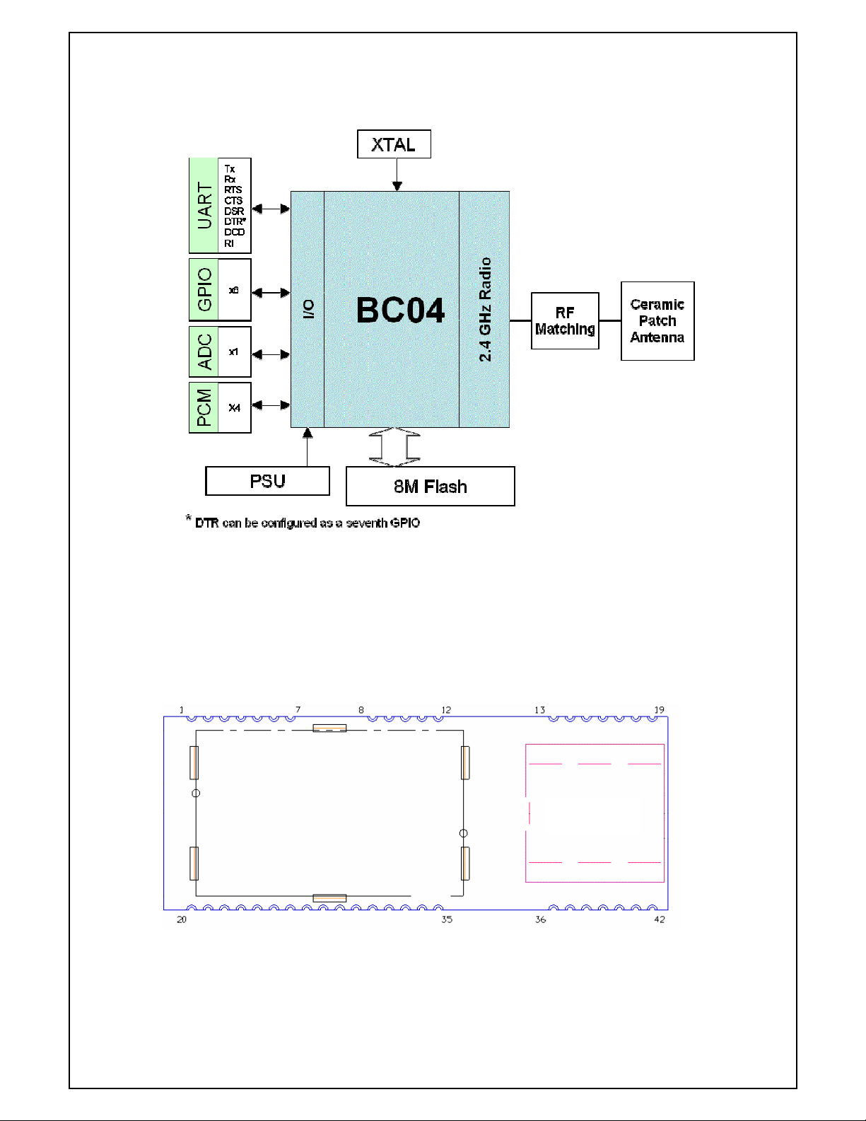
3. Functional Block Diagram
www.ezurio.com
3.1 Connection Diagram
The Module is connected to a “mother” PCB by direct soldering to edge pads. Pads adjacent to the
antenna do not provide an electrical connection, but are used for additional mechanical stability.
Antenna
© 2007 Ezurio Ltd DSH_BT024-00100_1v6 3
Page 4
www.ezurio.com
3.2 Pin Descriptions
The table below defines the pin functions. Refer to the previous section for the pin location.
Pin
No.
Signal Description Pin
No.
Signal Description
1 Vcc 2 USB D+
3 USB D- 4 GND
5 RESET Reset I/P * 6-19 N/C Do not Connect
20 GND 21-33 N/C Do not Connect
34 MPIO_10 (LED1) I/O for Host 35 MPIO_11 (LED2) I/O for Host
36-42 N/C Do not Connect
* The reset line has a fixed 10kOhm pull up resistor to ground.
3.3 Electrical Specifications
3.3.1 Absolute Maximum ratings
Absolute maximum ratings for supply voltage and voltages on digital and analogue pins of the Module
are listed below; exceeding these values will cause permanent damage.
Parameter Min Max Unit
Peak current of power supply 0 100 mA
Voltage at digital pins -0.3 3.7 V
Voltage at POWER pin 3.6 7 V
3.3.2 Recommended Operating Parameters
3.3.2.1 Power Supply
Absolute maximum ratings for supply voltage and voltages on digital and analogue pins of the Module are listed
below; exceeding these values will cause permanent damage.
Parameter Min Max Unit
Peak current of power supply 0 100 mA
Voltage at digital pins -0.3 3.3 V
Voltage at POWER pin 3.3 7 V
3.3.2.2 Power Supply
Signal Name Pin No I/O Voltage level Comments
Vcc 1 I 3.3V to 7.0V I
GND 4, 20, 29
The module contains a power on reset circuit that ensures the module is reset at power on. The internal reset
circuit is triggered when the input voltage to the module drops below ~1.7V and is hence only suitable for
providing a power on reset signal. If the supply voltage to the module can drop below the minimum voltage level
in normal operation, then it is recommended that an external brownout circuit is provided to assert the module
reset and to ensure that the module is reset when the module supply voltage drops below 3.1V.
= 30mA
typ
© 2007 Ezurio Ltd DSH_BT024-00100_1v6 4
Page 5
www.ezurio.com
This will ensure that the module will return to an operational state when the supply voltage comes back within
specification. For example, if the module supply can drop to 2.7V and then be restored to 3.3V there is no
guarantee that the module will still be operational unless the reset signal has been asserted.
3.3.2.3 UART Specific Recommendations
Function Signal Name Pin No I/O Signal level Comments
USB D- 3 I VILmax =0.3vdd_usb
VIHmin =0.7vdd_usb
USB D+ 2 I VILmax =0.3vdd_usb
VIHmin =0.7vdd_usb
Normally inactive.
Pull to GND
through 10K
Normally inactive.
Pull to GND
through 10K
Reset RESET 5 I Threshold 2.6V Active LOW
Terminology: USB Signal Levels. vdd_usb refers to the internal voltage generated by the LDO
regulator on the module, which is typically 3.3V. Hence 0.3vdd_usb and 0.7vdd_usb correspond to
1.0V to 2.3V. If Vcc falls below the recommended minimum of 3.6V, these values will be reduced.
3.3.2.4 General Purpose I/O and ADC
Signal Name Pin No I/O Signal level Comments
GPIO 4, 5, 6, 7,
8, 9
GPIO 3 27 I or O O/P : VOLmax=0.2V
ADC 0 37 I Range 0 – 1.8V ADC
36, 35,
6, 7, 38,
34
I or O O/P : VOLmax=0.2V
VOHmin=2.8V
I/P : VILmax=0.8V
VIHmin=2.1V
VIHmax=3.4V
VOHmin=2.8V
I/P : VILmax=0.8V
VIHmin=2.1V
VIHmax=3.4V
GPIO_4 and 5 are shared with the
onboard LED pads.
GPIO_9 is also used for
PCM_SLVCLK.
Shared with DTR
PIO lines can be configured through software to be either inputs or outputs with weak or strong pull-ups or pulldowns. At reset, all PIO lines are configured as inputs with weak pull-downs.
3.3.2.5 PCM Interface
Signal Name Pin No I/O Signal level Comments
PCM_CLK 32 I or O O/P : VOLmax=0.2V
VOHmin=2.8V
I/P : VILmax=0.8V
VIHmin=2.1V
VIHmax=3.4V
PCM_IN 31 I VILmax=0.8V
VIHmin=2.1V
VIHmax=3.4V
PCM_SYNC 30 I or O O/P : VOLmax=0.2V
VOHmin=2.8V
I/P : VILmax=0.8V
© 2007 Ezurio Ltd DSH_BT024-00100_1v6 5
If unused keep pins open
Page 6
www.ezurio.com
VIHmin=2.1V
VIHmax=3.4V
PCM_OUT 33 O VOLmax=0.2V
VOHmin=2.8V
PCM_SLV_CLK
(GPIO9)
O O/P : VOLmax=0.2V
VOHmin=2.8V
Available as a clock when two
connected devices are both in PCM
slave mode.
Shared with GPIO_9
4. I/O Characteristics
4.1 Power Consumption
The hardware specification for the Module allows for a voltage range of 3.3 to 7.0 at Vcc. Tests have
shown that there is no significant difference in current draw when Vcc is 5 or 6V. Tests have shown
that where power drain is an issue, it is best to keep Vcc at the lower end of the range.
With regards to operating mode the significant modes are; idle, waiting for a connection, inquiring,
initiating a connection, sniff and connected. With connected mode, it is also relevant to differentiate
between no data being transferred and when data is being transferred at the maximum rate possible.
The firmware within the USB/HCI module will always attempt to place the module into the lowest
possible power configuration.
5. DC Characteristics
5.1 RF Performance
5.1.1 Transmit Power
Conducted Transmit Power min: 1.0mW (0dBm) max: 4mW (6dBm)
Antenna Gain +2dBi typ.
Effective Transmit Power min:0dBm Max: +6dBm
Output power can be reduced by program control via the HCI interface
5.1.2 Receive Sensitivity
Receive Sensitivity (Typ) -86dBm (at 25°C)
Antenna Gain +2dBi typ
Effective Receive Sensitivity -88dBm (at 25°C)
6. Functional Description
The Embedded USB / HCI Bluetooth module is a fully featured HCI Bluetooth product and requires
only power and an external higher layer Bluetooth stack to implement full Bluetooth communication.
© 2007 Ezurio Ltd DSH_BT024-00100_1v6 6
Page 7

www.ezurio.com
The integrated, high performance antenna together with the RF and Base-band circuitry provides the
Bluetooth wireless link and the USB interface provides a connection to the host system.
6.1 GPIO Port
Eight lines of programmable bi-directional input/outputs (I/O) are provided that can be accessed
either via the UART port, or Over The Air (OTA) from a second Bluetooth unit. These can be used as
data inputs or to control external equipment. By using these in OTA mode, an embedded Bluetooth
Serial module can be used for control and data acquisition without the need for any additional host
processor. A further line can be used as an input.
Each of the GPIO ports can be independently configured to be either an Input or Output. A selection
of ports can be accessed synchronously.
The ports are powered from VCC. The mode of these lines can be configured and the lines are
accessed via S Registers in the range 623 to 629.
Low latency I/O can be accessed by using Ezurio’s I/O via an enhanced inquiry process.
6.2 PCM CODEC Interface
PCM_OUT, PCM_IN, PCM_CLK and PCM_SYNC carry up to three bi-directional channels of voice data,
each at 8ksamples/s. The format of the PCM samples can be 8-bit A-law, 8-bit µ-law, 13-bit linear or
16-bit linear. The PCM_CLK and PCM_SYNC terminals can be configured as inputs or outputs,
depending on whether the module is the Master or Slave of the PCM interface.
In applications where the PCM master cannot supply a clock signal, the module can be configured to
generate a clock signal on this GPIO: PCM_SLVCLK. Please contact an Ezurio FAE for further details.
The Module is compatible with the Motorola SSI TM interface and interfaces directly to PCM audio
devices including the following:
6.2.1 Compatible Codec Chips
PCM_OUT, PCM_IN, PCM_CLK and PCM_SYNC carry up to three bi-directional channels of voice data, each at
8ksamples/s. The format of the PCM samples can be 8-bit A-law, 8-bit µ-law, 13-bit linear or 16-bit linear. The
PCM_CLK and PCM_SYNC terminals can be configured as inputs or outputs, depending on whether the module is
the Master or Slave of the PCM interface. Please contact an Ezurio FAE for further details.
The Module is compatible with the Motorola SSI TM interface and interfaces directly to PCM audio devices
including the following:
• Winbond W61360 13-bit linear CODEC (Motorola MC145483 compatible)
• OKI MSM7702 single channel A-law and µ-law CODEC
• OKI MSM7705 four channel A-law and µ-law CODEC
The default codec support is for the Winbond W61360
• Codec development boards that mate with the EZURiO Wireless Developers Kit are available for each of
the three codecs listed above.
6.3 ADC
The module provides access to one 8-bit ADC. This provides an input range of 0mV to 1,800mV,
which can be read using S register 701.
Suitable external scaling and over-voltage protection should be incorporated in your design. The
module provides 5 samples per second at the UART with a baud rate of 115,200 or above.
Low latency access of the upper 6 bits of the ADCs can be obtained by using Ezurio’s I/O via an
enhanced inquiry process.
© 2007 Ezurio Ltd DSH_BT024-00100_1v6 7
Page 8

www.ezurio.com
6.4 LEDs
Pads are provided to allow two LEDs to be added for diagnostic purposes. They are controlled by an
S registers 624 and 625 to display the status of various parameters and are useful for debug and
test.
7. Integrated Firmware
7.1 Bluetooth Stacks
Most users will use the Embedded USB / HCI Bluetooth module with a pre-qualified Bluetooth stack.
The USB interface has been configured to present the device as a generic Bluetooth module. This
allows it to be plugged directly into most upper layer Bluetooth stacks, where it will enumerate and
start operating.
The module has been tested with the following stacks and requires no further drivers for these.
• Windows XP SP1 (we recommend the use of SP2)
• Windows XP SP2
• Windows XP embedded
• Windows CE
• Windows Vista (beta)
Ezurio can supply a Widcomm Windows stack that runs on Windows 98, 2000, ME and XP and which
provides a wider range of profiles than the Microsoft stacks. There is an additional per machine
license for the Widcomm stack.
7.1.1 Features of the HCI Stack
7.1.1.1 Standard Bluetooth v2.0 + EDR mandatory functionality:
• Adaptive frequency hopping (AFH), including classifier
• Faster connection - enhanced inquiry scan (immediate FHS response)
• LMP improvements
• Parameter ranges
7.1.1.2 Optional Bluetooth v2.0 + EDR functionality supported:
• Adaptive Frequency Hopping (AFH) as Master and Automatic Channel Classification
• Fast Connect - Interlaced Inquiry and Page Scan plus RSSI during Inquiry
• Extended SCO (eSCO), eV3 +CRC, eV4, eV5
• SCO handle
• Synchronisation
© 2007 Ezurio Ltd DSH_BT024-00100_1v6 8
Page 9

7.1.1.3 Standard Bluetooth components:
• Baseband (including LC)
• LM
• HCI
• Standard USB v1.1 HCI Transport Layer
• All standard radio packet types
(2)
(1)
• Full Bluetooth data rate, enhanced data rates of 2 and 3Mbps
•
Operation with up to seven active slaves
(1)
• Scatternet v2.5 operation
• Maximum number of simultaneous active ACL connections: 7
• Maximum number of simultaneous active SCO or eSCO connections: 3
• Operation with up to three SCO / eSCO links, routed to one or more slaves
• All standard SCO voice coding, plus transparent SCO
• Standard operating modes: Page, Inquiry, Page-Scan and Inquiry-Scan
• All standard pairing, authentication, link key and encryption operations
(2)
www.ezurio.com
• Standard Bluetooth power saving mechanisms: Hold, Sniff and Park modes, including Forced
Hold
• Dynamic control of peers' transmit power via LMP
• Master/Slave switch
• Broadcast
• Channel quality driven data rate
• All standard Bluetooth test modes
(1) This is the maximum all owed by Bluetooth v2.0 + EDR specification.
(2) Supports all combinati ons of active ACL and SCO channels f or both master and slave operation, as specified by the Bl uetooth v2.0 + EDR
specification.
7.2 Additional Stack Functionality
The firmware extends the standard Bluetooth functionality with the following features:
Hardware low power modes: Shallow Sleep and Deep Sleep. The chip drops into modes that
significantly reduce power consumption when the software goes idle.
8. Interfaces
8.1 USB Interface
The embedded USB / HCI module contains a full speed (12Mbits/s) USB interface that is capable of
driving a USB cable directly. No external USB transceiver is required. The device operates as a USB
peripheral, responding to requests from a master host controller such as a PC. Both the OHCI and the
UHCI standards are supported. The set of USB endpoints implemented can behave as specified in the
USB section of the Bluetooth specification v2.0+EDR. The module only operates as a USB slave.
The module contains inline resistors to provide a match for the characteristic impedance of a USB
cable as defined by the USB standard.
© 2007 Ezurio Ltd DSH_BT024-00100_1v6 9
Page 10

www.ezurio.com
The module contains a USB pull-up resistor. This pulls the USB+ pin weakly high when the USB
interface is ready to enumerate. It signals to the USB host that it is a full speed (12Mbit/s) USB
device. This pull-up is implemented as a current source, and is compliant with section 7.1.5 of the
USB specification v1.2. It pulls USB+ high to at least 2.8V when loaded with a 15kΩ 5% pull-down
resistor (in the hub/host) when VCC is 3.6V or higher. This presents a Thevenin resistance to the host
of at least 900Ω.
8.1.1 USB Enumeration
The embedded USB / HCI module enumerates with the following information:
Device Descriptor:
bcdUSB: 0x0200
bDeviceClass: 0xE0
bDeviceSubClass: 0x01
bDeviceProtocol: 0x01
bMaxPacketSize0: 0x40 (64)
idVendor: 0x04BF
idProduct: 0x0320
bcdDevice: 0x2652
iManufacturer: 0x01
iProduct: 0x02
iSerialNumber: 0x00
bNumConfigurations: 0x01
Current Config Value: 0x01
Device Bus Speed: Full
Device Address: 0x03
Open Pipes: 5
Endpoint Descriptor:
bEndpointAddress: 0x81
Transfer Type: Interrupt
wMaxPacketSize: 0x0010 (16)
bInterval: 0x01
Endpoint Descriptor:
bEndpointAddress: 0x02
Transfer Type: Bulk
wMaxPacketSize: 0x0040 (64)
bInterval: 0x01
Endpoint Descriptor:
bEndpointAddress: 0x82
Transfer Type: Bulk
wMaxPacketSize: 0x0040 (64)
bInterval: 0x01
Endpoint Descriptor:
bEndpointAddress: 0x03
Transfer Type: Isochronous
wMaxPacketSize: 0x0000 (0)
bInterval: 0x01
Endpoint Descriptor:
© 2007 Ezurio Ltd DSH_BT024-00100_1v6 10
Page 11

www.ezurio.com
bEndpointAddress: 0x83
Transfer Type: Isochronous
wMaxPacketSize: 0x0000 (0)
bInterval: 0x01
9. Low Power Modes
The embedded USB / HCI module supports all of the standard low power modes as specified by the
Bluetooth 2.0 + EDR standard.
In addition the firmware contains power management which will automatically place the device in
sleep modes whenever there is a period of inactivity.
9.1 Low Power Modes using Sniff
Bluetooth connections are master/slave in nature. A master sends packets and a slave has to
acknowledge that packet in the next timeslot. Timeslots in Bluetooth are 625 microseconds wide. This
implies that a master will always know when packets will be sent and received, which further means it
is able to optimise power usage by switching on power hungry circuitry only when needed.
A slave on the other hand does NOT have prior knowledge of when a packet will be received and has
to assume that a packet will be received from a master on every receive slot. This means that it has
to leave its receiving circuitry on for most of the receive slot duration. The result of this is high power
consumption, where a slave with no data transmission still consumes around 31mA whereas a master
consumes only 6mA.
This problem was identified very early in the evolution of Bluetooth (especially since headsets spend
all their time as a slave in a Bluetooth connection) and it was solved by having a mode called Sniff,
with appropriate lower layer negotiating protocol.
Sniff mode during connection is basically an agreement between the slave and its master that data
packets will only be exchanged for N timeslots every M slots. The slave can then assume that it will
never be contacted during N-M slots, and so can switch its power hungry circuitry off. The
specification goes further by also specifying a third parameter called ‘timeout’ (T) which specifies
‘extra’ timeslots that the slave will agree to listen for after receiving a valid data packet. Put another
way, if a data packet is received by the slave, then it knows that it MUST carry on listening for at
least T more slots. If within that T slot time period another data packet is received, then the timer is
restarted. This mechanism ensures low power consumption when there is no data transfer – at the
expense of latency. When there is a lot of data to be transferred, it acts as if sniff mode were not
enabled.
It is stated above that during sniff mode, a slave listens for N slots every M slots. The Bluetooth
specification states that a master can have up to 7 slaves attached to it with all slaves having
requested varying sniff parameters. It may therefore be impossible to guarantee that each slave gets
the M parameter it requested. In light of this, the protocol for enabling sniff mode specifies that a
requesting peer specify the M parameter as a minimum and maximum value. This will allow the
master to interleave the sniff modes for all slaves attached. This is illustrated in the diagram below.
For this reason, the sniff parameters are specified in the Embedded Intelligent Bluetooth Module via
four S registers. S Register 561 is used to specify ‘N’, S Register 562 is used to specify ‘T’ and S
Registers 563/564 are used to specify minimum ‘M’ and maximum ‘M’ respectively. Although the
specification defines these parameters in terms of timeslots, the S register values have to be
specified in units of milliseconds and the firmware does the necessary translation to timeslots.
High Power Consumption
Low Power Consumption
Data Exchange
T
© 2007 Ezurio Ltd DSH_BT024-00100_1v6 11
N
Slots
Slots
Data Exchange
Data Exhange
Data Exchange
Data Exchange
T
T
Slots
Slots
T
Slots
N
Data Exchange
Slots
T
Slots
N
Slots
Page 12

10. Enhanced Data Rate
www.ezurio.com
EDR has been introduced with Version 2.0 of the Bluetooth standard to provide 2x and 3x
rates with minimal disruption to higher layers of the Bluetooth stack. Ezurio’s embedded USB/HCI
module provides support for both of these new data rates and is compliant with the Bluetooth
v2.0+EDR specification.
At the baseband level EDR utilises both the same 1.6kHz slot rate and the 1MHz symbol rate as
defined for the basic data rate. Where EDR differs is that each symbol in the payload portion of a
packet represents 2 or 3-bits. This is achieved using two new distinct modulation schemes. These are
summarised below. Link Establishment and management are unchanged and still use GFSK for both
the header and payload portions of these packets.
(1) The inclusion of 3x data rates is optional.
Date Rate Scheme Bits Per Symbol Modulation
Basic Data Rate 1 GFSK
EDR 2 ∏/4 DQPSK
EDR 3 8DPSK (Optional)
(1)
data
Basic Rate and Enhanced Data Rate Packet Structure
11. Application Information
11.1 Antenna Position
The antenna used on the Embedded USB/HCI Bluetooth module is designed to be largely immune
from the effects of proximity detuning. Normally, antennas operating at 2.4GHz are affected by their
surroundings, so that great care is needed in their placement and orientation.
The Embedded USB/HCI Module can be used in most locations and orientations and is only marginally
affected by the presence of a significant ground plane in close proximity.
The antenna distribution is close to isotropic, which means that the orientation of mounting has only a
limited effect on the overall range. However the optimum range is achieved when the two antennae
are directly facing each other
The module should not be located in a sealed metal enclosure, as this will act as a Faraday cage and
severely attenuate the radio signal. A distance of 6mm has been allowed between the metal shield
and the antenna to allow the antenna to protrude through a slow in a metal enclosure.
The antenna finish may tarnish as a result of environmental effects and handling. This is a cosmetic
effect and does not affect the RF performance.
© 2007 Ezurio Ltd DSH_BT024-00100_1v6 12
Page 13

www.ezurio.com
11.2 External Antenna Module
The dimensions for this module are identical to the Surface Mount Module, but the antenna is
replaced with a U.FL connector.
The module is certified for use with the EZURiO external antenna ACC-008. If an alternative antenna
is connected, it will invalidate the RF and Bluetooth approvals for the module.
The antenna connector is a U.FL connector, supplied by Hirose. Mating connectors with cables are
available from Hirose and their distributors, and also from other cable suppliers. The data sheet for
the connector series is available at http://www.hirose.co.jp/cataloge_hp/e32119372.pdf
11.3 Power Supply Considerations
The power supply for the Module has to be a single voltage source of Vcc within the range of 3.3V to
70 V. It must be able to provide sufficient current in a transmit burst. This can rise to 65mA.
11.4 Power-On-Reset (Power Cycling and Brown Out
considerations).
The Module is provided with an active low reset pin. Upon the application of power, the Power On
Reset circuit built into the Module will ensure that the unit starts correctly. The internal reset circuit
is triggered when the input voltage to the module drops below ~1.7V and is hence only suitable for
providing a power on reset signal. If the supply voltage to the module can drop below the minimum
voltage level in normal operation, then it is recommended that an external brownout circuit is
provided to assert the module reset and to ensure that the module is reset when the module supply
voltage drops below 3.1V.
This will ensure that the module will return to an operational state when the supply voltage comes
back within specification. For example, if the module supply can drop to 2.7V and then be restored to
3.3V there is no guarantee that the module will still be operational unless the reset signal has been
asserted.
11.5 RF Shield
To meet FCC requirements and to facilitate IR soldering, all modules are supplied with a soldered RF
shield. This meets the requirement that users may not be able to access RF circuitry without special
tools. Removal of the shield may negate RF approvals.
© 2007 Ezurio Ltd DSH_BT024-00100_1v6 13
Page 14

www.ezurio.com
11.6 Mounting the Module onto the application platform
The antenna (Brown square component on top side of PCB) is designed to minimise detuning effects
from nearby components and metalwork. However, it is good design practise to ensure that other
active circuitry is kept away from the antenna.
The proximity of the antenna to large metallic objects can affect the range and performance of the
system. Designers should carefully consider the location of the Module and the type of enclosure
material that is used.
No tracks should be present on the top layer of the board on which the module is soldered, as these
may cause inadvertent connections to test pads. The recommended land pattern for the mother PCB
is detailed below
12. Qualification
12.1 Bluetooth Qualification Process
The following safety precautions must be observed during all phases of the operation, usage, service
or repair of any application incorporating this Module. Manufacturers of the RF equipment are advised
to convey the following safety information to users and operating personnel and to incorporate these
guidelines into all manuals supplied with the product. Failure to comply with these precautions
violates safety standards of design, manufacture and intended use of the product. Ezurio assumes no
liability for customer failure to comply with these precautions.
12.2 Safety Information:
Switch off the Bluetooth device before boarding an aircraft. Make sure it cannot be switched on
inadvertently. The operation of wireless appliances in an aircraft is forbidden by many airlines to
prevent interference with communications systems. Applications that could result in use on aircraft
should carry appropriate warnings.
Some airlines may permit use of Bluetooth. Check before use.
© 2007 Ezurio Ltd DSH_BT024-00100_1v6 14
Page 15

www.ezurio.com
12.3 Qualifications
12.3.1 RF approvals
The Embedded USB/HCI Bluetooth Module is qualified as a Bluetooth Subsystem. This means that if
it is combined with a higher level Bluetooth stack that is also qualified as a Subsystem, then no
further qualification is required. Final products incorporating Bluetooth technology should be listed
with the Bluetooth qualification body according to the guidelines available on www.bluetooth.org.
The manufacturer must state the Ezurio part number and product reference in his literature in order
to meet the requirements of the Bluetooth and regulatory approvals.
A list of the countries where the Module is approved will be provided by Ezurio as required. As a
minimum the product is listed in Europe, Scandinavia and USA. Ezurio assumes no liability for
customer failure to comply with national RF approvals.
12.3.1.1 Radio.
R&TTE EN 300 328-2 V1.1.1 (2000-07)
EN 301 489-1 V1.3.1 (2001-09)
12.3.1.2 EMC Emissions.
FCC15B Class B
EN55022 Class B
12.3.1.3 EMC Immunity.
EN55024 Class
12.3.1.4 Environmental.
EN300 019-2-4 v2.2.2 (2003-2004)
12.3.1.5 Medical
EN60601-1-2
12.3.1.6 Automotive
SAE1455:REVAug94 Paragraph 4.10.4 (shock)
SAE1455:REVAug94 Paragraph 4.9.4.2 (random)
Emission test to 95/54/EC
© 2007 Ezurio Ltd DSH_BT024-00100_1v6 15
Page 16

12.4 Safety and Regulatory Statements
complies with the appropriate essential requirements of the Article 3 of
the R&TTE and the other relevant provisions, when used for its intended
950: 1992 Safety of information technology equipment +
Amendment A1:1993, Amendment A2:1993, Amendment A3:1995,
s with the basic restrictions
300 GHz)
Protection requirements with respect to electromagnetic compatibility
tibility and
Magnetic Compatibility (EMC)
tions
2001), Radio Equipment and Systems (RES);
Wideband transmission systems; Technical characteristics and test
conditions for data transmission equipment operating in the 2,4 GHz ISM
ques. Part 2:
Harmonized EN covering essential requirements under article 3(2) of the
12.4.1 Europe – EU Declaration of Conformity
www.ezurio.com
DECLARATION OF CONFORMITY
In accordance with Annex IV of the EU directive 1999/5/EC
Ezurio declare under our responsibility that the Bluetooth Module
purpose.
Health and Safety requirements contained in Article 3 (1) a)
EN 60
Amendment A4:1997, Amendment A11:1997
EN 50371: Generic standard to demonstrate the compliance of lowpower electronic and electrical apparatu
related to human exposure to electromagnetic fields (10 MHz – General public
Art.3 (1) b)
EN 301489-17 V1.1.1 (09-2000), Electromagnetic Compa
radio spectrum Matters (ERM); Electro
standard for radio equipment and services; Part 17: Specific condi
for wideband data HiperLAN equipment
Means of the efficient use of the radio frequency spectrum
EN 300328-2 V1.2.1 (11-
band and using spread spectrum modulation techni
R&TTE directive.
Registered in England
www.ezurio.com No. 5178293
12.4.2 FCC and Industry Canada Statements
This device complies with part 15 of the FCC Rules. Operation is subject to the following two
conditions: (1) This device may not cause harmful interference, and (2) this device must accept any
interference received, including interference that may cause undesired operation.
© 2007 Ezurio Ltd DSH_BT024-00100_1v6 16
Page 17

www.ezurio.com
Changes or modifications not expressly approved by the party responsible for compliance could void
the user's authority to operate the equipment.
12.4.2.1 FCC Labelling requirement
If the FCC ID is not visible when the module is installed inside another device, then the outside of the
device into which the module is installed must also display a label referring to the enclosed module.
This exterior label can use wording such as the following: “Contains Transmitter Module FCC ID:
PI401B” or “Contains FCC ID: PI401B.” Any similar wording that expresses the same meaning may be
used.
13. Environmental
13.1 Operating temperatures
Parameter Min Typ Max Unit
Operating temp (standard product) -40 25 +85 °C
13.2 Storage temperature
Parameter Min Max Unit
Storage temp -40 +125 °C
13.3 Reliability
Parameter Test Comment
Thermal Shock 200 cycles -40ºC /+85ºC 30 min 1 cycle/hour
Vibration Continuous operation at 60 Hz,
2mm stroke
Shock 50G 11ms Half Sine Wave 6 axis x 3 cycles each axis
Moisture Resistance
High Temp Storage 125ºC, 360 hours
Low Temp Storage -40ºC, 240 hours
High Temp/Humidity
Operation
Thermal shock -40 to 60ºC in 30min 200 cycles with continuous
Electro Static Discharge EN55024:1998 & IEC61000-4-3
Drop Test 75cm to concrete, 3 axis x 2
60ºC, 90%RH, 360 hours
cycles per corner
15g max sine wave, 12 hours
operation
© 2007 Ezurio Ltd DSH_BT024-00100_1v6 17
Page 18

14. Physical Dimensions (all dimensions in mm)
14.1 Top View
www.ezurio.com
14.2 Bottom View
14.3 Side View
© 2007 Ezurio Ltd DSH_BT024-00100_1v6 18
Page 19

www.ezurio.com
14.4 Labelling
The module has a label indicating the part number and the unique Bluetooth address of the module.
14.5 Ordering Information
Part Number Description
TRBLU024-00100
TRBLU024-00200
TRBLU024-00300
TRBLU024-00400
TRBLU024-001NA Embedded Module with no antenna and HCI
TRBLU024-002NA
TRBLU024-003NA
TRBLU024-004NA
Embedded Module with integrated ceramic
antenna and HCI firmware
Embedded Module with integrated ceramic
antenna and H4 firmware
Embedded Module with integrated ceramic
antenna and H5 firmware
Embedded Module with integrated ceramic
antenna and BCSP firmware
firmware
Embedded Module with no antenna and H4
firmware
Embedded Module with no antenna and H5
firmware
Embedded Module with no antenna and BCSP
firmware
15. Related Documents
The firmware incorporated into the Embedded HCI/USB Bluetooth Module is more fully described in
Firmware release notes available from Cambridge Silicon Radio. Details of the HCI interface are
provided in the Bluetooth specification.
• Bluetooth Core 2.0 Specification – www.bluetooth.org
• Bluecore4-External Datasheet for BC417143B-IQN-E4 July 2005 - CSR
© 2007 Ezurio Ltd DSH_BT024-00100_1v6 19
Page 20

www.ezurio.com
16. Disclaimers
EZURIO’S BLUETOOTH PRODUCTS ARE NOT AUTHORISED FOR USE AS CRITICAL COMPONENTS IN
LIFE SUPPORT DEVICES OR SYSTEMS WITHOUT THE EXPRESS WRITTEN APPROVAL OF THE
MANAGING DIRECTOR OF EZURIO LTD.
The definitions used herein are:
a) Life support devices or systems are devices which (1) are intended for surgical implant into the
body, or (2) support or sustain life and whose failure to perform when properly used in accordance
with the instructions for use provided in the labelling can reasonably be expected to result in a
significant injury to the user.
b) A critical component is any component of a life support device or system whose failure to perform
can be reasonably expected to cause the failure of the life support device or system, or to affect its
safety or effectiveness.
Ezurio does not assume responsibility for use of any of the circuitry described, no circuit patent
licenses are implied and Ezurio reserves the right at any time to change without notice said circuitry
and specifications.
16.1 Data Sheet Status
This data sheet contains data from the Preliminary specification. Supplementary data will be
published at a later date. Ezurio Ltd reserves the right to change the specification without notice in
order to improve the design and supply the best possible product.
Where reference is made to related products from other suppliers, Ezurio takes no responsibility for
the information, availability or performance of such products.
Please check with Ezurio Ltd for the most recent data before initiating or completing a design.
16.2 Warranty
Ezurio warrants that its products shall conform to Ezurio’s published specifications and remain free
from defects in materials and workmanship under normal, proper and intended use for a period of
two (2) years from date of purchase, provided that proof of purchase be furnished with any returned
equipment.
If during the warranty period any component part of the equipment becomes defective by reason of
material or workmanship, and Ezurio is immediately notified of such defect, Ezurio shall at its option
supply a replacement part or request return of equipment, freight prepaid, to its designated facility
for repair. In the event no trouble is found on products returned for repair, Ezurio reserves the right
to charge the customer its standard published repair charge.
This warranty shall not apply to any products that have been subject to misuse, bending, twisting,
neglect, alteration, improper installation, testing or unauthorized repair performed by anyone other
than an Ezurio designated repair facility. Any non-warranty repairs or maintenance shall be at Ezurio’s
standard rates in effect at the time.
This warranty is in lieu of all other warranties, whether expressed, implied, or statutory, including but
not limited to, implied warranties or merchantability and fitness for a particular purpose. In no event
shall Ezurio be liable, whether in contract, in part, or on any other basis, for any damage sustained by
its customers or any other person arising from or related to loss of use, failure or interruption in the
operation of any products, or delay in maintenance, or for incidental, consequential, in direct, or
special damages or liabilities, or for loss of revenue, loss of business, or other financial loss arising
out of or in connection with the sale, lease, maintenance, use, performance, failure, or interruption of
these products.
© 2007 Ezurio Ltd DSH_BT024-00100_1v6 20
 Loading...