

Page 1

QUALCOMM
Incorporated
5775 Morehouse Drive,
San Diego, California 92121-1714 US
200 Series and Accessory Installation Guide
Qualcomm Mobile Computing Platform
80-J9968-1 Rev. A
Month 2009
Page 2

QUALCOMM Incorporated
5775 Morehouse Drive
San Diego, CA 92121-1714
U.S.A.
Copyright
All rights reserved.
QUALCOMM, OmniTRACS, OmniExpress, SensorTRACS, QTRACS, GlobalTRACS, and
TrailerTRACS are registered trademarks of QUALCOMM Incorporated in the United States and may be
registered in other countries.
Qualcomm Enterprise Services, QES, T2, MVPc, and TruckMAIL are trademarks of QUALCOMM
Incorporated. QES is a service mark of QUALCOMM Incorporated.
Other product and brand names may be trademarks or registered trademarks of their respective owners.
Qualcomm endeavors to ensure that the information in this document is correct and fairly stated, but
Qualcomm is not liable for any errors or omissions. Published information may not be up to date, and it is
important to confirm current status with Qualcomm.
This technical data may be subject to U.S. and international export, re-export or transfer (expo rt ) laws.
Diversion contrary to U.S. and international law is strictly prohibited.
80-J9968-1 Rev. A
Month 2009
© 2009 QUALCOMM Incorporated.
Page 3

Contents
Important Safety Information
Safety Definitions ................................................................................................xi
Safety Advice ......................................................................................................xi
Chapter 1 How the Qualcomm® Mobile Computing Platform 200 Series Works
MCP200 Overview ............................................................................................1-2
Why MCP200 Makes Companies More Efficient ..............................................1-2
MCP200 Component Description .....................................................................1-3
CDMA Wireless Network and PCS ...................................................................1-4
How MCP200 Uses PCS ............................................................................1-4
Optional Data Satellite ......................................................................................1-5
GPS Network ....................................................................................................1-5
How the MCP200 Uses GPS .....................................................................1-5
Wi-Fi® Network .................................................................................................1-5
How the MCP200 Uses Wi-Fi® ..................................................................1-5
What Is MCP200? .............................................................................................1-6
Chapter 2 Component Overview
Equipment Installation ......................................................................................2-2
Wireless Interface Box 200 (WIB200) ...............................................................2-3
Wireless Interface Box (WIB200) Cable .....................................................2-3
Optional Satellite Data Modem (SDM) ..............................................................2-3
Satellite Data Modem (SDM) Cable ...........................................................2-3
Display Interface Unit 200 (DIU200) .................................................................2-4
Display Cable .............................................................................................2-4
Procedures for Using the DIU200 ..............................................................2-4
Mobile Application Server 200 (MAS200) .........................................................2-5
Backup Battery .................................................................................................2-6
Accessory Cable for the Qualcomm® MCP200 .........................................2-6
Speaker Switch Cable ................................................................................2-6
Power Cable ...............................................................................................2-6
Optional Remote Control Device (RCD) ...........................................................2-7
Optional Accessories for the MCP200 ..............................................................2-7
80-J9968-1 Rev. A MAY CONTAIN U.S. AND INTERNATIONAL EXPORT CONTROLLED INFORMATION iii
Page 4

Chapter 3 General Wiring and Installation Guidelines
Making Electrical Connections .........................................................................3-2
Approved Qualcomm Electrical Connectors ..............................................3-2
Wire Stripping ............................................................................................3-2
Butt Splicing................................................................................................3-3
Crimping .....................................................................................................3-4
Ring Terminals .........................................................................................3-10
Proper Grounding ...........................................................................................3-10
General Installation Guidelines ......................................................................3-11
Routing and Protecting Cables ......................................................................3-11
Chapter 4 Installation Planning
Installation Guidelines ......................................................................................4-2
Safety, Reliability, and Accessibility ...........................................................4-2
Typical Installation Sequence ..........................................................................4-2
Typical Installation Locations for MCP200 Components ..................................4-3
Conventional Vehicle Types ......................................................................4-4
Straight Truck Vehicle Types (All Makes) ..................................................4-6
Cabover Engine Vehicle Types (All Makes) ..............................................4-6
Special Cable Ordering Instructions for Tilt Cabs ......................................4-7
Installation Planning Worksheets for the MCP200 Components .....................4-8
Tools and Supplies Recommended for Installations ......................................4-11
Qualcomm Approved Sealants ................................................................4-11
Contents
Chapter 5 Mobile Application Server 200 (MAS200) Installation
General Installation Guidelines ........................................................................5-2
Installing the Backup Battery into the MAS200 ................................................5-2
Installing the MAS200 into the Mounting Surface ............................................5-3
Selecting a Mounting Location ...................................................................5-3
Securing the MAS200 ................................................................................5-5
Installing the Power Cable ...............................................................................5-5
Power Cable Run .......................................................................................5-5
Power Cable Routing .................................................................................5-5
Low Voltage Disconnects (LVDs) ..............................................................5-5
Power Cable Wire Connections .................................................................5-6
Grounding Guidelines ......................................................................................5-7
Installing the Accessory Cable .........................................................................5-7
Cable Run ..................................................................................................5-8
Connecting Cables to the MAS200.............................................................5-9
DO NOT COPY
Chapter 6 Wireless Interface Box 200 (WIB200) Antenna Installation
General Installation Guidelines ........................................................................7-2
Option A—Antenna Installation Using VHB Tape ............................................7-2
iv
MAY CONTAIN U.S. AND INTERNATIONAL EXPORT CONTROLLED INFORMATION 80-J9968-1 Rev. A
Page 5

Contents
Antenna Surface Preparation .....................................................................7-2
Option B—Mount Method Installation Using Hardware ....................................7-3
Mount Surface Preparation ........................................................................7-3
Routing the WIB200 Cable ...............................................................................7-4
Connecting the Antenna Cable to the MAS200 ................................................7-4
Chapter 7 Optional Satellite Data Modem (SDM) Installation
General Installation Guidelines .........................................................................8-2
Selecting a Mount .......................................................................................8-2
Orienting the SDM on the Mount ......................................................................8-2
Installing Mounting Bolts ...................................................................................8-3
Line-of-Sight Requirements ..............................................................................8-4
Trailer Swing Area ............................................................................................8-5
Installing the SDM Cable ..................................................................................8-5
Connecting the SDM Cable ........................................................................8-5
SDM Cable Run .........................................................................................8-6
SDM Cable Installation ...............................................................................8-6
Connecting the SDM Cable to the MAS200 .....................................................8-7
PY
Chapter 8 Display Interface Unit 200 (DIU200) Installation
General Installation Guidelines .........................................................................9-2
Selecting a Mounting Location ...................................................................9-2
Installing the DIU200 Holster Using Well-nut Fasteners ...................................9-3
Installing the DIU200 Cable ..............................................................................9-4
DIU200 Cable Run .....................................................................................9-4
Connecting the Display Cable to the DIU200 ...................................................9-4
Inserting the DIU200 into the Holster ................................................................9-5
Connecting the Display Cable to the MAS200 ..................................................9-6
N
O
T
O
D
Chapter 9 Optional Text-to-Speech (TTS) Installation
General Installation Guidelines .......................................................................10-2
Selecting a Mounting Location .................................................................10-2
Installing the Remote Control Device (RCD) ..................................................10-2
Connecting the RCD to the Accessory Cable ..........................................10-2
Selecting a Speaker ........................................................................................10-3
Speaker Requirements .............................................................................10-3
Choosing a Speaker .................................................................................10-3
Option A—Connecting to an Existing or Shared Speaker ..............................10-4
Connecting Speaker Switch Cable to Accessory Cable ...........................10-5
Option B—Connecting to a Dedicated 8-ohm Speaker ..................................10-6
CO
Chapter 10 Vehicle Data Bus Connections
Vehicle Data Source Overview .......................................................................11-2
80-J9968-1 Rev. A MAY CONTAIN U.S. AND INTERNATIONAL EXPORT CONTROLLED INFORMATION v
Page 6

J1939 Data Bus .......................................................................................11-2
J1708/J1587 Data Bus ............................................................................11-2
Traditional Sensors ..................................................................................11-2
Vehicle Data Source Selection .......................................................................11-3
Guidelines for Connecting to the J1939 Data Bus .........................................11-3
J1939 Pre-installation Check Out ...................................................................11-4
Resistance Test (to Verify that J1939 Is Present) ...................................11-4
Checking the MCP200 Accessory Cable for CAN0 and CAN1 ................11-5
Option 1—Connecting J1939 Using CAN 1 (for All After-Market Installations) 11-5
Making the Connection ............................................................................11-6
Option 2—Connecting J1939 Using CAN0 (for Most OEM Prewires) ............11-8
Making the Connection.............................................................................11-9
Connecting J1708 /J1587 ............................................................................11-10
Verifying Data Source Connectivity ..............................................................11-11
Chapter 11 System Verification
What Is Basic Qualcomm® MCP200 System Verification? ...........................12-2
MCP200 Display Unit Screens .......................................................................12-2
MCP200 System Screen .........................................................................12-3
MCP200 OVT/CDMA Screens .................................................................12-4
MCP200 SDM Screens ............................................................................12-5
MCP200 GPS Screen ..............................................................................12-6
MCP200 Config Screen ...........................................................................12-7
MCP200 Engineering Screen ..................................................................12-8
MCP200 CER Screen ..............................................................................12-8
VDS (Status) Screen ...............................................................................12-9
Flowchart—Basic MCP200 System Verification ..........................................12-11
Basic MCP System Verification Procedure ..................................................12-13
Qualcomm® MCP System Verification Form ...............................................12-18
DO NOT COPY
Contents
Chapter 12 SensorTRACS® Performance Monitoring Verification
SensorTRACS® System Overview ................................................................13-2
Performing SensorTRACS® System Verification ...........................................13-2
Conducting a Road Test ..........................................................................13-2
SensorTRACS® System Display Screens .....................................................13-3
Accessing the SensorTRACS® Screens .................................................13-3
Summary Screen......................................................................................13-4
Performance Screen.................................................................................13-5
Parameters Screen...................................................................................13-6
Odometer Screen ....................................................................................13-7
PTO Screen..............................................................................................13-8
Installer Screen ........................................................................................13-9
Special Alert Display Messages ...................................................................13-12
Warning Messages ................................................................................13-12
vi
MAY CONTAIN U.S. AND INTERNATIONAL EXPORT CONTROLLED INFORMATION 80-J9968-1 Rev. A
Page 7

Contents
Power Take-off (PTO) Overview ...................................................................13-12
PTOP (Power Take-off Pump)/PTOC (Power Take-off Compressor).....13-13
PTO Data Input Verification Procedure ........................................................13-14
Chapter 13 Vehicle Maintenance Installation
Vehicle Maintenance Overview ......................................................................14-2
Feature Requirements ..............................................................................14-2
Connecting the J1939 Wires ...........................................................................14-3
Enabling a Vehicle for Vehicle Maintenance ..................................................14-3
Vehicle Maintenance System Verification .......................................................14-4
Chapter 14 TrailerTRACS® System Installation
TrailerTRACS® System Overview ..................................................................15-2
Hardware Requirements ..........................................................................15-2
TrailerTRACS® System Wiring for the Truck .................................................15-2
Fuse Kit Installation ..................................................................................15-2
TrailerTRACS® System Verification ...............................................................15-3
Enabling the Option for the TrailerTRACS® System ...............................15-3
Trailer Connection/Disconnection ............................................................15-4
TrailerTRACS® Diagnostic Screen ..........................................................15-5
Refrigeration Status Screen .....................................................................15-6
T
CO
PY
Chapter 15 Buzzer Installation
Buzzer Overview .............................................................................................17-1
Mounting Location ..........................................................................................17-2
Installation Guidelines .....................................................................................17-2
Installation Verification ....................................................................................17-2
N
O
O
D
Chapter 16 Remote Message Waiting Light (RMWL) Installation
RMWL Overview .............................................................................................18-1
Installing the Remote Message Waiting Light .................................................18-2
Installation Verification ....................................................................................18-2
Chapter 17 Wired Panic Button Installation
Wired Panic Button Overview .........................................................................19-1
Installing the Panic Button ..............................................................................19-2
Installation Verification ....................................................................................19-4
Automated Panic Button Test System Dial-in Procedure .........................19-4
Chapter 18 In-Cab Printer Installation
Wiring Configuration .......................................................................................20-2
80-J9968-1 Rev. A MAY CONTAIN U.S. AND INTERNATIONAL EXPORT CONTROLLED INFORMATION vii
Page 8

Installation Guidelines ....................................................................................20-2
Location ...................................................................................................20-2
Cables ......................................................................................................20-2
Mounting Bracket ...........................................................................................20-2
Installing the Printer .......................................................................................20-3
Installation Verification ...................................................................................20-4
Return Material Authorization (RMA) Process ...............................................20-4
O’Neil Printer Parts List ..................................................................................20-4
Chapter 19 In-Cab Scanner Installation
Installation Guidelines ....................................................................................21-2
Location ...................................................................................................21-2
Scanner Cable .........................................................................................21-2
Mounting the Scanner ....................................................................................21-2
Scanner Mounting Option ........................................................................21-2
Holster Mounting Option ..........................................................................21-2
Installing the Scanner .....................................................................................21-3
Calibrating the Scanner ..................................................................................21-3
Sending a Scan ..............................................................................................21-4
Cleaning the Scanner .....................................................................................21-5
Return Material Authorization (RMA) Process ...............................................21-5
BCS Solutions Scanner Parts List ..................................................................21-6
Contents
Appendix A Wiring Diagrams and Charts
Qualcomm® MCP200 Electrical Diagram ........................................................A-2
Qualcomm® MCP200 Wiring Diagram ............................................................A-3
Power Cable Pin Callouts ................................................................................A-4
Optional Satellite Data Modem (SDM) Cable 9-Pin Connector Callouts ..........A-5
Primary Accessory Cable Pin Callouts .............................................................A-6
Secondary Accessory Cable Pin Callouts ........................................................A-7
Display Interface Unit 200 (DIU200) Connector Pin Callouts ...........................A-8
Six-pin Data Link Connector Pin Callouts ........................................................A-9
Nine-pin Data Link Connector Pin Callouts ....................................................A-10
Radio Connector Pin Callouts ........................................................................A-11
CAN Conductor Cable ....................................................................................A-12
DO NOT COPY
Appendix B Environmental and Power Requirements
MCP200 Environmental and Power Requirements ..........................................B-2
Appendix C Standard RMA Procedure
The Return Material Authorization Process .....................................................C-1
How to Obtain an RMA Number .......................................................................C-2
Required Information .................................................................................C-2
viii
MAY CONTAIN U.S. AND INTERNATIONAL EXPORT CONTROLLED INFORMATION 80-J9968-1 Rev. A
Page 9

Contents
Creating an RMA On-line...........................................................................C-4
RMA Policies ...................................................................................................C-4
What to Return/Not Return ........................................................................C-4
Where to Return Equipment ......................................................................C-5
“Past Due” Equipment ...............................................................................C-6
Customer-Damaged Equipment ................................................................C-6
Missing, Lost, Stolen, or Destroyed Equipment ........................................C-6
Permanent Fleet Size Reduction Request Form .......................................C-7
Appendix D Upgrading the Qualcomm® MCP Using Secure Digital Cards
Checking the Software Versions Installed .......................................................D-2
SD Card Instructions ........................................................................................D-3
Upgrading Only the MAS Software ..................................................................D-3
Upgrading the MAS Operating System and MAS Software .............................D-4
Upgrading the SDM Software ..........................................................................D-5
Upgrading the MDU Software ..........................................................................D-6
PY
Appendix E Preventive Maintenance Inspection
How Often Should Inspections Be Performed? ...............................................E-2
Inspecting the Mobile Application Server 200 (MAS200) ................................E-2
Inspecting the Display Interface Unit 200 (DIU200) .........................................E-4
Inspecting the Wireless Interface Box 200 (WIB200) and the Optional Satellite Data Modem
(SDM) ..............................................................................................................E-6
Verifying TrailerTRACS® System Connections ...............................................E-9
T
O
CO
N
Appendix F Component and Document Information
DCNs for Documents Referenced in this Guide ..............................................F-2
MCP200 System Component MCNs Referenced in this Guide ....................... F-2
MCNs for Sealants and Lubricants Referenced in this Guide ......................... F-6
MCN for Qualcomm-recommended Torque Wrench Referenced in this Guide F-6
Appendix G Feedback Form
Feedback Form ................................................................................................G-1
Company Information ................................................................................G-1
Documentation Content .............................................................................G-2
Documentation Format ..............................................................................G-2
O
D
Glossary
Index
80-J9968-1 Rev. A MAY CONTAIN U.S. AND INTERNATIONAL EXPORT CONTROLLED INFORMATION ix
Page 10

Contents
DO NOT COPY
x
MAY CONTAIN U.S. AND INTERNATIONAL EXPORT CONTROLLED INFORMATION 80-J9968-1 Rev. A
Page 11

Safety Definitions
The following Caution and Warning definitions are intended to advise the driver when it is
safe to use a display unit.
CAUTION indicates a potentially hazardous situation which, if not avoided, may result in
minor or moderate injury. It may also be used to alert against unsafe practices.
WARNING indicates a potentially hazardous situation which, if not avoided, could result in
death or serious injury.
Safety Advice
The following Safety Advice is provided for drivers, installers, and application developers who
use and/or locate all types of display units.
If you are a Driver, do not use a display unit when the vehicle is in motion.
If you are an Installer, do not locate the display unit, including third-party devices, where it
obstructs the driver’s field of vision, distracts the driver from the driving task, o r interferes with
the driver’s operation of controls or displays. The following label is to be posted in clear view
for the driver to see.
Important Safety Information
If you are a Third-party Device Manufacturer or Application Developer, it is your
responsibility to provide appropriate warnings regarding the safe use of your device(s) in
conjunction with Qualcomm
his attention from the road while driving a vehicle.
80-J9968-1 Rev. A MAY CONTAIN U.S. AND INTERNATIONAL EXPORT CONTROLLED INFORMATION xi
DO NOT COPY
®
equipment. Applications should not require the driver to divert
Page 12

Safety Advice Important Safety Information
FCC notice:
Caution: Any changes or modifications to this device not explicitly approved by
manufacturer could void your authority to operate this equipment.
This equipment complies with FCC radiation exposure limits set forth for an
uncontrolled environment. This equipment should be installed and operated with
minimum 20 cm between the radiator and your body. This transmitter must not be
collocated or operating in conjunction with any other antenna or transmitter unless
authorized to do so by the FCC.
IC Notice:
The device’s user manual does not contain the following or equivalent statement as
per RSS-GEN section 7.1.5: Operation of this device is subject to the following two
conditions: (1) this device may not cause interference, and (2) this device must
accept any interference, including interference that may cause undesired operation
of the device.
DO NOT COPY
xii
MAY CONTAIN U.S. AND INTERNATIONAL EXPORT CONTROLLED INFORMATION 80-J9968-1 Rev. A
Page 13

1
How the Qualcomm® Mobile Computing Platform 200 Series Works
Topics in this chapter provide a basic overview of the MCP 200 Series and how its
components interact to deliver effective, two-way communications and other value-added
services.
MCP200 Overview. . . . . . . . . . . . . . . . . . . . . . . . . . . . . . . . . . . . . . . . . . . . . . . . . . 1-2
Why MCP200 Makes Companies More Efficient. . . . . . . . . . . . . . . . . . . . . . . . . . . 1-2
MCP200 Component Description. . . . . . . . . . . . . . . . . . . . . . . . . . . . . . . . . . . . . . . 1-3
CDMA Wireless Network and PCS . . . . . . . . . . . . . . . . . . . . . . . . . . . . . . . . . . . . . 1-4
Optional Data Satellite . . . . . . . . . . . . . . . . . . . . . . . . . . . . . . . . . . . . . . . . . . . . . . . 1-5
GPS Network . . . . . . . . . . . . . . . . . . . . . . . . . . . . . . . . . . . . . . . . . . . . . . . . . . . . . . 1-5
Wi-Fi® Network . . . . . . . . . . . . . . . . . . . . . . . . . . . . . . . . . . . . . . . . . . . . . . . . . . . . 1-5
What Is MCP200? . . . . . . . . . . . . . . . . . . . . . . . . . . . . . . . . . . . . . . . . . . . . . . . . . . 1-6
For technical questions, contact Qualcomm Enterprise Services (QESSM) Customer Support.
Customer Support is staffed 24 hours a day, 365 days a year:
In the United States, call 800-541-7490
In Canada, call 800-863-9191
DO NOT COPY
80-J9968-1 Rev. A MAY CONTAIN U.S. AND INTERNATIONAL EXPORT CONTROLLED INFORMATION 1-1
Page 14

MCP200 Overview How the Qualcomm® Mobile Computing Platform 200 Series Works
MCP200 Overview
MCP200 is a high bandwidth mobile computing platform designed to help increase customer
service, reduce operating costs, enhance driver productivity, and ensure vehicle safety.
®
MCP200 offers multi-mode communications (terrestrial and Wi-Fi
optional); and delivers more processing power on the mobile unit, an increased number of
hardware ports, and a Windows
Data transmitted through the MCP200 is backward compatible and interoperable with the
host, so customers can access information across various Qualcomm platforms, such as
MCP 100 Series, OmniTRACS
Communications System, and Untethered Asset Management Service.
®
Embedded Standard operating system.
®
Mobile Communications System, OmniExpress® Mobile
are standard, satellite is
Why MCP200 Makes Companies More Efficient
• Companies can maintain two-way contact with their vehicles and drivers 24 hours a day.
• Dispatchers can send pickup and delivery information directly to drivers, keeping vehicles
on the road.
• Text-to-speech alerts drivers of incoming messages and their importance, so drivers can
choose to immediately listen to messages without pulling off the road.
• Dispatchers know when vehicles are expected to arrive at locations, and can pass that
information on to customers.
• Provides dispatchers with vehicle location and position history information by tracking the
location of each MCP200 using latitude and longitude or distance and direction from
landmarks (usually large towns and cities).
• Drivers can inform the dispatcher of road conditions or problems.
• Optional devices allow monitoring of driver performance, engine diagnostics, trailer
locations, and refrigeration status.
DO NOT COPY
• Decision support software enables customers to optimize assets and inform shippers and
consignees of load status.
• Over-the-air software upgrades allow drivers to remain on the road rather than having to
stop at service centers.
• Display interface unit 200 (DIU200) provides a color graphical display, with a sliding
keyboard that integrates touchscreen functionality, extended temperature range, and
improved clarity for delivering critical information to drivers.
• Hours of service data ensures regulatory compliance.
• On-board navigation application provides truck-specific route mappings.
1-2
• International Fuel Tax Agreement (IFTA) simplifies fuel reporting for inter-state operations.
• Helps with safety and accident prevention.
• Optimizes fuel management.
MAY CONTAIN U.S. AND INTERNATIONAL EXPORT CONTROLLED INFORMATION 80-J9968-1 Rev. A
Page 15
How the Qualcomm® Mobile Computing Platform 200 Series Works MCP200 Component Description
K
w
PWR
IO 1
IO 2
9
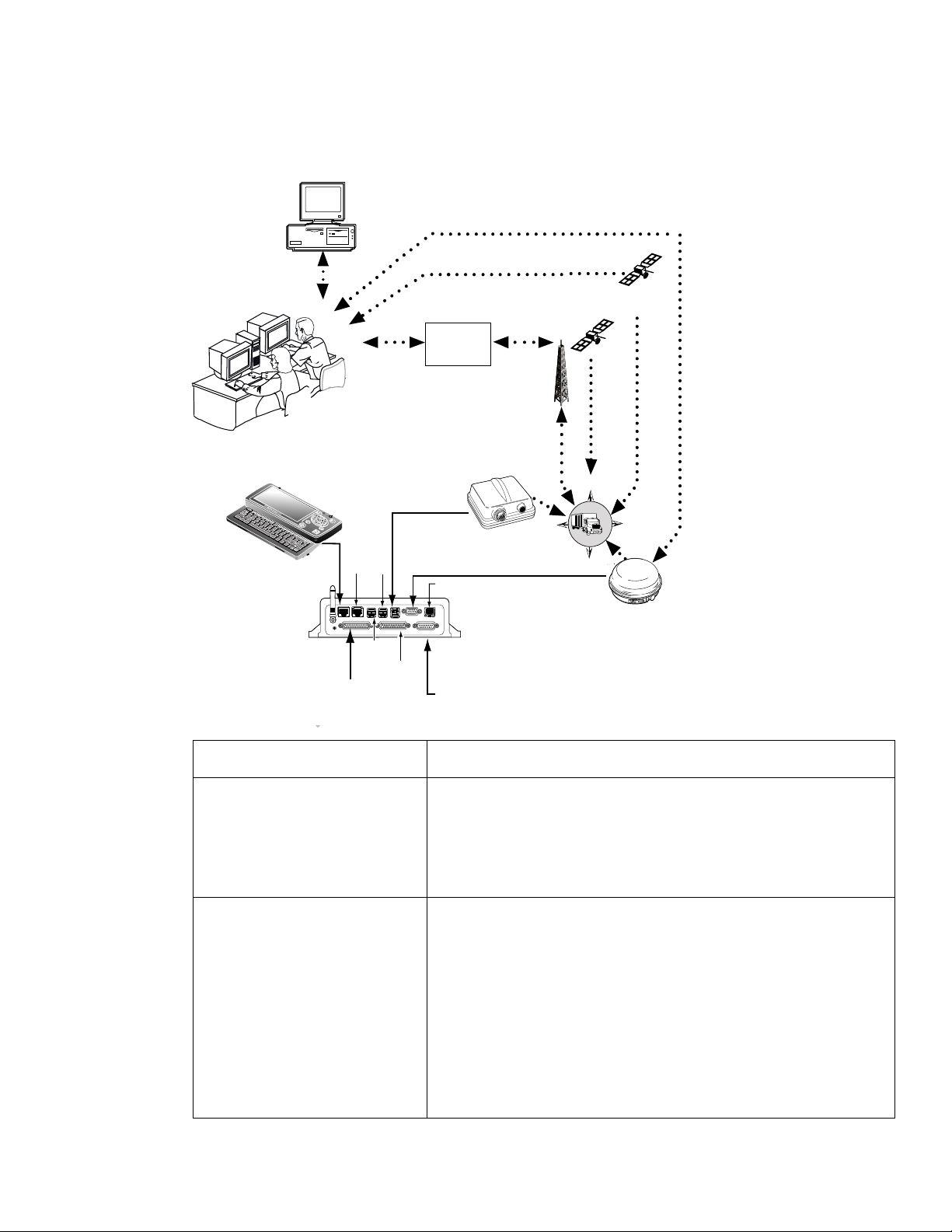
MCP200 Component Description
Customer dispatch
computer
Shift
Ctn
Fn
Esc
Tab
F
1
Alt
F
2
F
3
F
4
F
5
F
6
F
7
F
8
lkXZ
lkXZ
Ctn
Home
DIU200
MAS200
F
9
F
1
0
F
1
0
Shift
End
Up
Pg
F
1
1
F
1
2
Backspac
Insert
e
Delete
S
y
m
A
b
o
A
l
A
Dn
Pg
NOC
IDD
IO 2
Primary
Accessory
cable
USB
1/2
USB
3G
Secondary
IO 1
Accessory
cable
O
Terrestrial
network
LAN
PWR
N
Power/
Ignition
WIB200
O
GPS
Satellite
N
W
CO
S
T
Data
Satellite
PY
E
SDM
09AAA_01
Component Description
Network Operations Center
(NOC)
D
• Responsible for processing and managing message
traffic between dispatch center and fleet.
• Within the NOC is the Network Management Computer
(NMC), which receives and handles message traffic.
• Located at QUALCOMM Incorporated, in San Diego, CA.
Qualcomm Dispatch
Software (QTRACS
software)
®
• Software on the trucking company’s dispatch computer
and dispatcher’s interface with the MCP200.
• Allows dispatcher to send and receive messages, request
MCP200 location information, and perform other dispatch
functions.
• QTRACS/400 and QTRACS/Windows customers
communicate with the NMC via dialup using PPTP or a
frame relay connection.
• QTRACS/Web customers communicate via the NMC
using RI/Web client over a PPTP connection.
80-J9968-1 Rev. A MAY CONTAIN U.S. AND INTERNATIONAL EXPORT CONTROLLED INFORMATION 1-3
Page 16

CDMA Wireless Network and PCS How the Qualcomm® Mobile Computing Platform 200 Series Works
Code Division Multiple
Access (CDMA)
Wireless Network
Optional Data Satellite • Handles all two-way message traffic between the vehicle
GPS Positioning Satellites • Uses 24 satellites to provide vehicle positioning
Mobile Computing Platform
200 (MCP200)
CDMA Wireless Network and PCS
• MCP200 uses CDMA technology to connect dispatchers and vehicles over the wireless
airwaves.
• The Personal Communications Service (PCS) System is a low-powered, higher frequency
competitive technology to cellular, ideal for “in-city” trucking and transport.
• Radio frequency (RF) signals are received from the
antenna by the MCP200 via the wireless interface box
(WIB200) from a wireless communication network, which
varies depending on geographic location.
and the NMC if you are using a satellite data modem
(SDM).
information.
• Driver’s interface with the Qualcomm platform and the
component that resides in the vehicle.
• Allows the driver to send and receive messages.
• Wherever a terrestrial wireless network exists, drivers can send messages to and receive
messages from dispatchers while traveling.
How MCP200 Uses PCS
• The MCP200 includes the MAS200, which consists primarily of a microprocessor, a
wireless modem module, and data storage.
• The user interface device (DIU200) is the driver’s display terminal that enables the driver
to read, write, and send messages.
• The antenna (located inside the WIB200) relays messages between dispatch and the
driver.
• The antenna receives and transmits wireless information to and from the MAS200.
• The antenna interfaces with local wireless networks. Communication is collected at the
PCS gateway and obtained by Qualcomm’s NOC where it is distributed to the dispatch
center . Disp atchers respond by send ing a message back to Qualcomm’s NOC, where it is
relayed to the PCS gateway and broadcast out to the wireless network to be picked up by
the vehicle’s antenna.
DO NOT COPY
1-4
MAY CONTAIN U.S. AND INTERNATIONAL EXPORT CONTROLLED INFORMATION 80-J9968-1 Rev. A
Page 17

How the Qualcomm® Mobile Computing Platform 200 Series Works Optional Data Satellite
Optional Data Satellite
• Used if you are using an SDM.
• Located approximately 22,300 miles over the equator at 83° west longitude (south of
Georgia).
• Uses Ku-band signals to handle all two-way message traffic between the vehicle and the
NMC.
• Sends the message along the forward message link to the MCP200.
• Receives the message back from the driver along the return message link.
GPS Network
• A worldwide radio-navigation system formed from a constellation of 24 satellites and their
ground stations.
• Uses satellites as reference points to calculate positions accurate to a matter of meters.
• Allows every square meter of the planet to have a unique address.
• Originally created for and used by the military.
PY
• Currently used in a number of industries, including construction, film, farming, computer,
transportation, telecommunication, and wireless.
• A standard feature of the MCP200.
How the MCP200 Uses GPS
• MCP200 receives positioning data from the GPS receiver, which is integrated inside the
antenna to determine location.
• NOC receives position data from the MCP200 whenever a message is sent to a vehicle
and acknowledged, and whenever a driver sends a message to a dispatcher.
• NOC automatically retrieves position data from the NOC at regular intervals and makes it
available to the dispatcher.
• Dispatcher can request a position report from the MCP200 at any time.
Wi-Fi® Network
• A wireless networking technology that uses radio waves to provide wireless high-speed
internet and network connections.
• Provides Wi-Fi enabled devices, such as PCs, game consoles, mobile phones, MP3
players, and PDAs, access to the internet when within range (“hotspot” area) of a wireless
network.
CO
T
O
N
O
D
• Applications and devices that support Wi-Fi are interoperable with one another.
• Based on IEEE 802.11 standards.
How the MCP200 Uses Wi-Fi®
80-J9968-1 Rev. A MAY CONTAIN U.S. AND INTERNATIONAL EXPORT CONTROLLED INFORMATION 1-5
Page 18

What Is MCP200? How the Qualcomm® Mobile Computing Platform 200 Series Works
What Is MCP200?
• Mobile part of the Qualcomm platform installed in a customer’s vehicle.
• Provides the driver with the ability to exchange messages with the dispatch center.
• Sends vehicle location information to the NOC.
• Each MCP200 has its own unique unit address which is the serial number on the MAS200.
This address is used by the NMC to route messages to the correct vehicle. The unit
address for a particular vehicle changes if the MAS200 in the vehicle is replaced.
• MCP200 operator, typically the driver, uses the display screens for creating, sending, and
reading messages; system verification; and troubleshooting.
Wireless Interface Box
(WIB200)
Antenna
Esc
Tab
F1
F2
Shift
F3
Ctn
F4
Fn
F5
Alt
F6
F7
F8
F9
F10
F10
F11
lkXZ
lkXZ
F12
Backspac
Insert
Ctn
e
Home
Delete
Shift
Symbol
End
Up
AAA
Pg
Dn
Pg
OPTIONAL
Satellite Data Modem
(SDM)
Display Interface Unit
(DIU200)
DO NOT COPY
OPTIONAL
Mobile Application
Server (MAS200)
• Standard components:
- Wireless interface box (WIB200)—Contains terrestrial and Wi-Fi
antennae that provide CDMA/GSM/UMTS communication.
- Mobile application server (MAS200)—Communication unit which contains the operating
circuitry and memory for the MCP200. The “black box” of the platform.
- Display interface unit (DIU200)—Standa rd display unit for the MCP200, which the driver
uses to communicate with the dispatcher. Consists of a color graphical display with a
Remote Control
Device (RCD)
®
08AAA_053
modems, and
1-6
MAY CONTAIN U.S. AND INTERNATIONAL EXPORT CONTROLLED INFORMATION 80-J9968-1 Rev. A
Page 19

How the Qualcomm® Mobile Computing Platform 200 Series Works What Is MCP200?
sliding keyboard that integrates touchscreen functionality , extended te mperature range,
and improved clarity for drivers.
• Optional components:
- Satellite data modem (SDM)—Contains the antenna that communicates with the
satellite and GPS receiver.
- Remote control device (RCD)—Small keypad that allows the driver to safely listen to
incoming messages without having to sop the vehicle and read the message(s) on the
display.
PY
D
CO
T
O
N
O
80-J9968-1 Rev. A MAY CONTAIN U.S. AND INTERNATIONAL EXPORT CONTROLLED INFORMATION 1-7
Page 20

What Is MCP200? How the Qualcomm® Mobile Computing Platform 200 Series Works
1-8
DO NOT COPY
MAY CONTAIN U.S. AND INTERNATIONAL EXPORT CONTROLLED INFORMATION 80-J9968-1 Rev. A
Page 21

2
Component Overview
Topics in this chapter provide a basic component and wiring overview of the Qualcomm®
mobile computing platform 200 (MCP200) installation.
• For planning and installation instructions, see Chapters 4–11.
• For optional accessory installation, refer to Optional Accessories for the MCP200 on
page 2-7.
Equipment Installation . . . . . . . . . . . . . . . . . . . . . . . . . . . . . . . . . . . . . . . . . . . . . . . 2-2
Wireless Interface Box 200 (WIB200) . . . . . . . . . . . . . . . . . . . . . . . . . . . . . . . . . . . 2-3
Optional Satellite Data Modem (SDM). . . . . . . . . . . . . . . . . . . . . . . . . . . . . . . . . . . 2-3
Display Interface Unit 200 (DIU200) . . . . . . . . . . . . . . . . . . . . . . . . . . . . . . . . . . . . 2-4
Mobile Application Server 200 (MAS200) . . . . . . . . . . . . . . . . . . . . . . . . . . . . . . . . 2-5
Backup Battery. . . . . . . . . . . . . . . . . . . . . . . . . . . . . . . . . . . . . . . . . . . . . . . . . . . . . 2-6
Optional Remote Control Device (RCD) . . . . . . . . . . . . . . . . . . . . . . . . . . . . . . . . . 2-7
Optional Accessories for the MCP200 . . . . . . . . . . . . . . . . . . . . . . . . . . . . . . . . . . . 2-7
For technical questions, contact Qualcomm Enterprise Services (QESSM) Customer Support.
Customer Support is staffed 24 hours a day, 365 days a year:
In the United States, call 800-541-7490
In Canada, call 800-863-9191
DO NOT COPY
80-J9968-1 Rev. A MAY CONTAIN U.S. AND INTERNATIONAL EXPORT CONTROLLED INFORMATION 2-1
Page 22
Equipment Installation Component Overview
SDM
SDM Cable
Accessory Connections
(e.g., RMWL, J1708, RCD, TTS)
Power Cable
Accessory Cable
Power Connections
MAS
Display Cable
Remote
Control Device
CB or
Stereo Speaker
Speaker
Cable
Media Display Unit
TMCP_SMCP
Satellite MCP Connection Points
MAS
Display
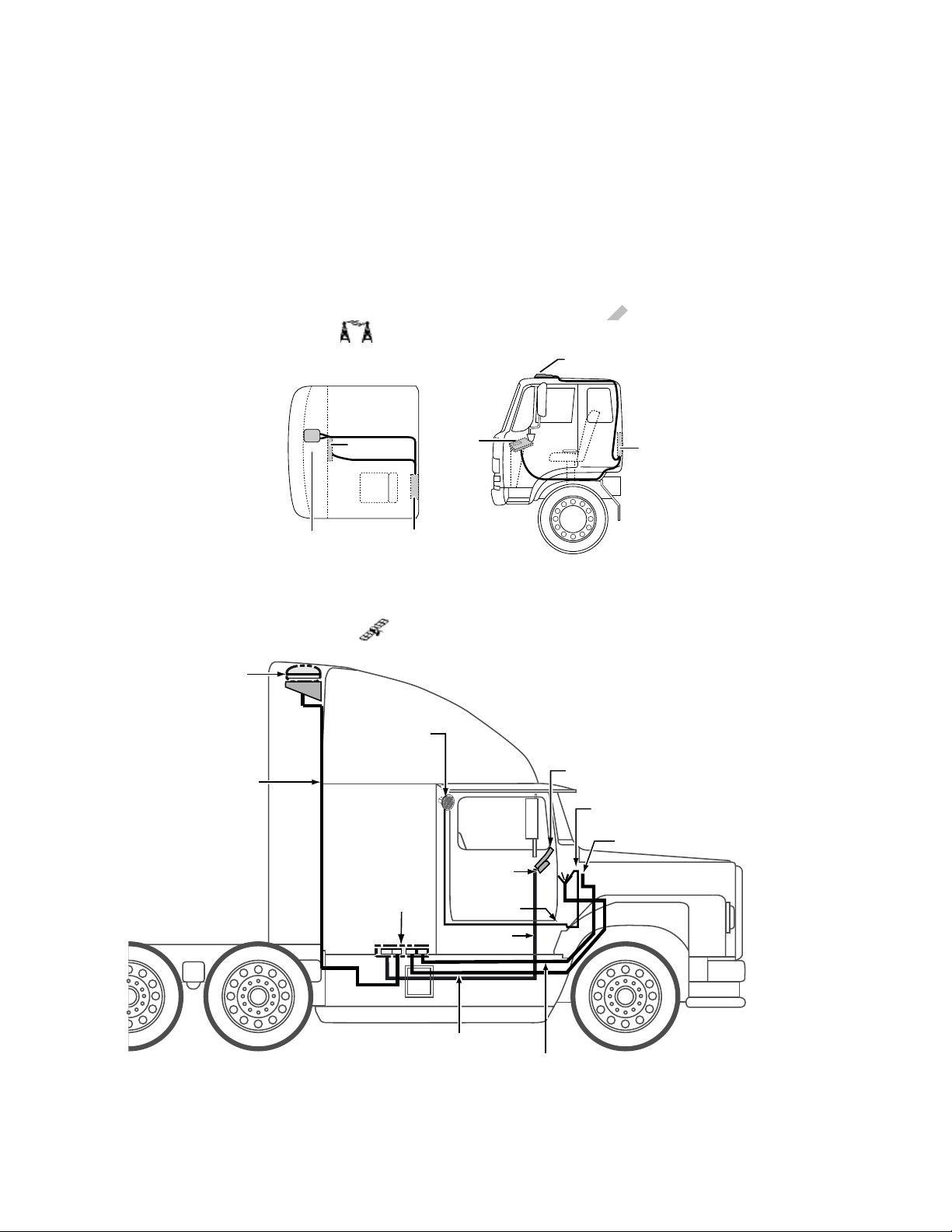
Typical truck cab - top view
MAS
Antenna
cable
Terrestrial
Antenna
Terrestrial
Antenna
Display
Terrestrial MCP Connection Points
Equipment Installation
Qualcomm MCP200 masterpack:
• Wireless interface box 200 (WIB200) • Cables
• Display interface unit 200 (DIU200) • Backup battery
• Mobile application server 200 (MAS200)
DO NOT COPY
2-2
MAY CONTAIN U.S. AND INTERNATIONAL EXPORT CONTROLLED INFORMATION 80-J9968-1 Rev. A
Page 23

Component Overview Wireless Interface Box 200 (WIB200)
Wireless Interface Box 200 (WIB200)
The WIB200 includes terrestrial and Wi-Fi® modems, and antennae that provide CDMA/
GSM/UMTS communication. The hardware provides reliable communication and GPS
positioning.
• Height: 3.4 inches
• Width: 6.5 inches
• Length: 6.5 inches
• Extended operating temperature range:
-30C to +70 C / -22F to +158F
• 802.11 compatible
• Lightweight housing for easy installation.
• Rugged design
PY
Wireless Interface Box (WIB200) Cable
• Connects the WIB200 to the MAS200.
• Standard length is two feet.
Optional Satellite Data Modem (SDM)
The SDM communicates bi-directionally via an antenna to a geostationary satellite. The SDM
is lightweight and rugged in design with strengthened antenna housing for protection against
weather and external elements.
• Height: 6.8 inches
• Diameter: 12 inches
• Weight: 7.0 pounds
• Operating temperature range:
-40C to +70C / -40F to +158F
• Connects with one Ku-band satellite for two-way data transmission. A secondary
frequency exists as a backup satellite.
• Robust sealing mechanism for use in all outdoor environments.
• Housing has the same bolt pattern as the OmniTRACS
(ACU) for ease of installation.
O
D
N
O
CO
T
®
antenna communication unit
Satellite Data Modem (SDM) Cable
• Connects the SDM to the MAS200.
• Standard length is 20 feet.
80-J9968-1 Rev. A MAY CONTAIN U.S. AND INTERNATIONAL EXPORT CONTROLLED INFORMATION 2-3
Page 24

Display Interface Unit 200 (DIU200) Component Overview
Display Interface Unit 200 (DIU200)
A color graphical display with sliding keyboard that integrates touchscreen functionality,
extended temperature range, and improved clarity for delivering
critical information to drivers.
• Dimensions—Open: 10.4 x 8.5 x 2.0 inches
Dimensions—Closed: 10.4 x 5.3 x 2.0 inches
• Weight: 3.2 pounds
• Screen size: 7-inch diagonal
• Resolution: 800 x 480
• Extended operating temperature range: -30C to +70C / -22F to +158F. Display brightness
is reduced at temperatures above +60C / +140F to reduce internal heat generation.
• Standard QWERTY keyboard with 4 arrow/navigation keys.
• Three indicator LEDs alert drivers of incoming messages, connectivity, and other
information.
• 16:9 aspect ratio color TFT LCD touchscreen includes stylus. Icon- and task- driven to
maximize driver efficiency.
• Holstered dash mount and tethered display allows for use anywhere in the cab.
• Display and keyboard are backlit, allowing the driver to distinguish keys in the dark. An
ambient light sensor adjusts backlight when it gets dark.
• Integrated speaker can be used for audio throughout the cab.
• One standard USB port for peripherals.
• Utilizes in-motion user interface to reduce driver distraction and increase safe driving.
• Touchscreen provides valid Cartesian touch coordinates for the entire active display
surface.
DO NOT COPY
Display Cable
• Connects the DIU200 to the MAS200.
• Standard length is 20 feet: 17 feet of straight cable; 3 feet of coiled cable.
Procedures for Using the DIU200
What to use for navigating the DIU200 touchscreen—PDA stylus (provided) or your
fingers.
What NOT to use for navigating the DIU200 touchscreen—pencils, pens, metal objects, or
any other devices which could possibly scratch the touchscreen.
2-4
What to use when cleaning the DIU200—a soft cloth and either plain water, glass cleaner,
or mild soap. Do not spray any liquid directly onto the DIU200.
MAY CONTAIN U.S. AND INTERNATIONAL EXPORT CONTROLLED INFORMATION 80-J9968-1 Rev. A
Page 25

Component Overview Mobile Application Server 200 (MAS200)
Mobile Application Server 200 (MAS200)
The hardware component that leverages the Windows® Embedded Standard operating
system to deliver computing intelligence, processing power, and
expansion capability.
• Dimensions: 9.7 x 6.5 x 2.4 inches
• Weight: 4.3 pounds
• Extended operating temperature range:
-40C to +70C / -40F to +158F
• Storage temperature range: -40C to +85C / -40F to +185F
• On-board memory: 8 GB of compact flash solid state memory and 1 GB RAM. Optional
16GB flash memory upgrade available.
• Rugged hardware is compliant to SAE xJ1455 vibration profiles.
• .NET framework version 3.5.
• Intel
• Backup battery for cold crank condition.
• Supports a wide range of port interfaces that allow connections to on-board equipment:
• Supports these other interfaces:
®
Extended Temperature Atom 1.3 GHz.
CO
- J1708 Bus connects to J1708 bus of older trucks.
- (2) J1939/CAN Bus connect to J1939 bus of newer trucks. Can be used to drive some
serial tachographs.
- (4) USB 2.0 Host Ports allow USB peripherals, such as handheld scanners,
keyboards, and storage devices.
- RS-232 Interface allows connectivity to devices, such as printers, barcode readers,
and scanners.
- Configurable Interface (RS-232 or RS-485) connects to modular truck interface
systems.
- Ethernet Port RJ45 Connector
- (2) Display Ports allow for in-dash infotainment system and one other display.
- (7) Power Drivers act as switches to control lights, buzzers, door locks, etc.
D
N
O
T
O
PY
- (6) Digital Inputs allow the MAS200 to sense door openings, button pushes, alarm
status, power takeoff (PTO) clutch position, etc.
- (2) Analog Inputs allow the MCP200 to read and react to analog values, such as
temperature, light levels, and humidity levels.
- Panic Button Input allows connection of a panic button for emergency driver
signaling.
- Engine and Vehicle Speed Inputs sense the speed of the engine and the vehicle.
80-J9968-1 Rev. A MAY CONTAIN U.S. AND INTERNATIONAL EXPORT CONTROLLED INFORMATION 2-5
Page 26

Backup Battery Component Overview
Pull Tab
Battery Pack
- (2) Tamper Detect Lines detect tampering with the SDM and WIB200.
- Decoy Tamper Detect Line detects tampering with decoy vehicle wiring.
- Indicator Box Output drives a warning lamp to alert drivers of overspeed or overrev.
- Tethered Asset Management Rec eiver allows the MAS200 to determine what trailer
is attached to the tractor.
- Audio Output drives a truck’s speakers which allow for voice navigation and
messaging prompts, i.e., text-to-speech.
Backup Battery
• Qualcomm MCP200 requires a rechargeable lead-acid
battery installed into the MAS200.
• For more specific information about the backup battery,
see Chapter 5.
• When vehicle power is lost to the MCP200, the backup battery allows the MAS200 to shut
down gracefully and properly store data. Without a healthy battery installed, there is a high
probability of experiencing data loss or corruption.
Accessory Cable for the Qualcomm® MCP200
• Connects accessories and options, such as the SensorTRACS system®, the
TrailerTRACS system, and the RCD and speaker to the MAS200 for text-to-spee ch (TTS)
play.
• Standard length is 20 feet.
• Does not support wiring for the CDU, Axle, RPM, PTOP, or PTOC.
Speaker Switch Cable
• Connects a vehicle into a speaker to play text-to-speech.
• Cable length is 8 feet.
• Do not need if a dedicated speaker is added to the vehicle for text-to-speech (TTS).
DO NOT COPY
Power Cable
• Connects the +12/24 VDC unswitched power source (battery), the +12/24 VDC switched
power (ignition), and the system ground to the MAS200.
• Standard length is 20 feet.
2-6
MAY CONTAIN U.S. AND INTERNATIONAL EXPORT CONTROLLED INFORMATION 80-J9968-1 Rev. A
Page 27

Component Overview Optional Remote Control Device (RCD)
Optional Remote Control Device (RCD)
An easily accessible in-cab device allowing drivers to easily manage message playback and
the text-to-speech (TTS) feature.
• Extended operating temperature range: -30C to +70C.
• Storage temperature range: -40C to +85C.
• Small and easy to mount to the vehicle dash.
Optional Accessories for the MCP200
Accessory Chapter
SensorTRACS system 13
Vehicle Maintenance 14
PY
TrailerTRACS system 15
Buzzer 17
CO
Remote message waiting light 18
Panic button 19
Printer 20
Scanner 21
N
T
O
O
D
80-J9968-1 Rev. A MAY CONTAIN U.S. AND INTERNATIONAL EXPORT CONTROLLED INFORMATION 2-7
Page 28

Optional Accessories for the MCP200 Component Overview
2-8
DO NOT COPY
MAY CONTAIN U.S. AND INTERNATIONAL EXPORT CONTROLLED INFORMATION 80-J9968-1 Rev. A
Page 29

General Wiring and Installation Guidelines
Topics in this chapter provide the Qualcomm-approved general methods for making
connections to cables and wires and the proper connectors to use to avoid potential
problems.
Making Electrical Connections. . . . . . . . . . . . . . . . . . . . . . . . . . . . . . . . . . . . . . . . . 3-2
Proper Grounding. . . . . . . . . . . . . . . . . . . . . . . . . . . . . . . . . . . . . . . . . . . . . . . . . . 3-10
General Installation Guidelines . . . . . . . . . . . . . . . . . . . . . . . . . . . . . . . . . . . . . . . 3-11
Routing and Protecting Cables . . . . . . . . . . . . . . . . . . . . . . . . . . . . . . . . . . . . . . . 3-11
If you have technical questions while reviewing this chapter, please contact Qualcomm
SM
Enterprise Services (QES
365 days a year:
) Customer Support. Customer Support is staffed 24 hours a day,
In the United States, call 800-541-7490
In Canada, call 800-863-9191
3
DO NOT COPY
80-J9968-1 Rev. A MAY CONTAIN U.S. AND INTERNATIONAL EXPORT CONTROLLED INFORMATION 3-1
Page 30
Making Electrical Connections General Wiring and Installation Guidelines
Making Electrical Connections
Approved Qualcomm Electrical Connectors
The only Qualcomm-approved electrical connectors are crimp butt splices and crimp ring
terminals. Qualcomm recommends Nylon insulated, seamless butt connectors with
inspection windows. Heat-shrinkable butt connectors are preferred. When butt splicing
multiple wires on one end of a butt splice and a different number of wires on the other end,
step-down butt splices are recommended.
WAR NI NG
Not following proper wiring guidelines and using improper crimps and butt splices
may cause intermittent connections and may result in unexpected truck down time or
system failure.
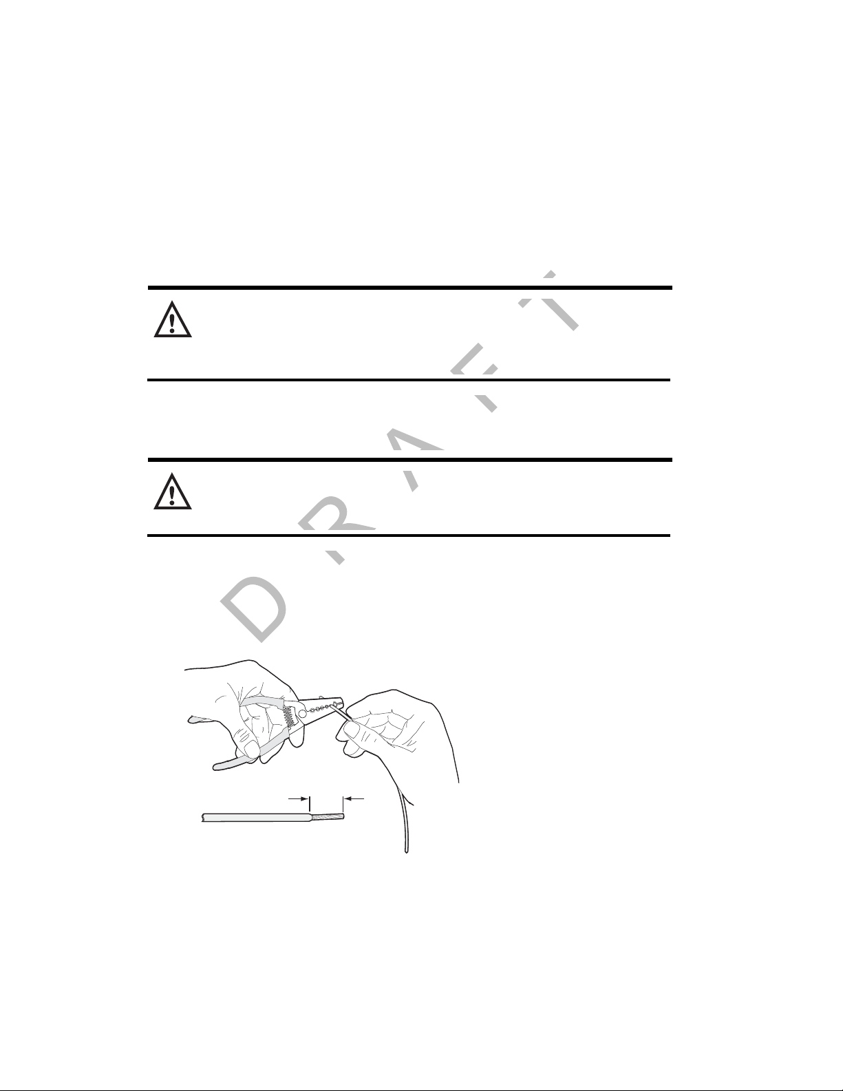
Wire Stripping
Caution
Use care in stripping wires. Vibration can cause nicked wires to fail. Using wire
cutters, knives, or other tools can damage the conductor wire and/or insulation.
Knowing and following proper wire stripping techniques is essential for performing successful
and safe electrical connections of all system components.
1. Using a wire stripper, strip approximately 1/4" off the end of an insulated wire.
DO NOT COPY
Strip
approx.
1/4"
03AAA_270a
3-2
2. After stripping the wire, verify that the wire is not severed, nicked, or damaged by the
stripping tool. If the wire has been properly stripped, it is ready to be butt spliced. If the
wire has been damaged, restrip the wire (see step 1.).
MAY CONTAIN U.S. AND INTERNATIONAL EXPORT CONTROLLED INFORMATION 80-J9968-1 Rev. A
Page 31

General Wiring and Installation Guidelines Butt Splicing
Butt Splicing
• Qualcomm recommends Nylon insulated, seamless butt connectors with inspection
windows.
• Heat-shrinkable butt connectors are preferred.
Butt splicing can be done inside and outside the cab or enclosure. See Butt Splicing
Connections Done Inside the Vehicle (Out of the Weather) on page 3-3 and Moisture
Protection for Connections Done Outside the Vehicle on page 3-7.
Make sure the size of the butt splice is appropriate for the job. A good butt splice has these
characteristics:
• The ends of the bare wires are visible through an inspection window.
• The ends of the wires “butt” up against the stop.
• The wires are not exposed beyond splice shielding.
• Crimping does not sever or damage the wires or insulation.
Butt Splicing Connections Done Inside the Vehicle (Out of the Weather)
1. Insert the stripped wires approximately half way into a butt splice, preferably one with
an inspection window for verifying the wire is in the correct position.
T
Push the stripped
wires to the inspection window
O
of the butt splice
CO
PY
N
O
D
Butt splice
03AAA_272
Inspection window
2. Repeat this process for the wire on the opposite end of the butt splice. Once a proper
butt splice is confirmed, it is important to properly crimp the butt splice to hold the
connection.
80-J9968-1 Rev. A MAY CONTAIN U.S. AND INTERNATIONAL EXPORT CONTROLLED INFORMATION 3-3
Page 32

Crimping General Wiring and Installation Guidelines
03AAA_90b
Crimp tooth
INSUL
Do NOT crimp wire here
Crimp here
INSUL
UNINSUL
UNINSUL
Crimping
• When crimping a butt-spliced wire or cable, be sure the insulated butt splice is crimped
using the insulated position on the crimp tool and not the crimping “tooth” of the tool.
• Crimping butt splices incorrectly can result in a severed wire and a failed wire connection.
Caution
DO NOT crimp on the crimp “tooth.”
1. Using a crimping tool, crimp the butt splice one end at a time. First, crimp the inside
crimp area where the wire has been stripped. Apply necessary pressure to this inside
area.
DO NOT COPY
3-4
MAY CONTAIN U.S. AND INTERNATIONAL EXPORT CONTROLLED INFORMATION 80-J9968-1 Rev. A
Page 33

General Wiring and Installation Guidelines Crimping
p
Note
The objective is to apply only the necessary pressure to crimp the butt splice closed and hold
the wire connections together. Do not apply so much pressure as to crush the butt splice and
sever the wire or the insulation on the wire.
Butt splice is visibly crushed,
WRONG
possibly damaging the wire
and the wire connection.
Some wires are exposed.
2. After crimping the inside of both ends of the butt splice on the “insulated” area of the
crimping tool, next crimp the outside of both ends of the butt splice.
CORRECT
Crimping is done properly,
protecting the wire and
the wire connection.
No exposed wires.
CO
PY
03AAA_277A
T
O
Wire crim
N
O
D
Crimping Tool
UNINSUL
INSUL
Crimp here
80-J9968-1 Rev. A MAY CONTAIN U.S. AND INTERNATIONAL EXPORT CONTROLLED INFORMATION 3-5
03AAA_271
Page 34

Crimping General Wiring and Installation Guidelines
Crimping locations
Outside crimp (insulated wire)
Inside crimp (stripped wire)
Outside crimp (insulated wire)
Inside crimp (stripped wire)
03AAA_273
3. Verify that the crimps are good and the wires have not been damaged.
4. Do a pull test. Pull on both ends of the wires to ensure a solid butt-spliced connection
exists. The crimped butt splice securely grips the insulated wires.
03AAA_282
WAR NI NG
If using heat shrinkable crimps, DO NOT use a heat gun or open flame near
combustible materials. Use a heat gun only when it is safe and appropriate to do so.
Protect surrounding wiring and other components when using a heat gun.
DO NOT COPY
3-6
MAY CONTAIN U.S. AND INTERNATIONAL EXPORT CONTROLLED INFORMATION 80-J9968-1 Rev. A
Page 35

General Wiring and Installation Guidelines Crimping
04AAA_22a
Wrap two
layers minimum
Peel Paper
Backing Off
Moisture Protection for Connections Done Outside the Vehicle
1. For crimps done outside the vehicle, when the crimps are verified to be good, use
plastic seal tape to wrap the entire connection. Use a minimum of two layers of seal
tape to completely wrap the connection.
• 3M industrial tape (tape sealant, vinyl/rubber mastic) is available in a 10’ roll from
Qualcomm (MCN# 800-01788-0168). To find a local or nationwide supplier, visit
http://www.3m.com (Mastic, Scotch
®
Vinyl).
PY
CO
T
O
N
O
D
80-J9968-1 Rev. A MAY CONTAIN U.S. AND INTERNATIONAL EXPORT CONTROLLED INFORMATION 3-7
Page 36

Crimping General Wiring and Installation Guidelines
Strain Relief With or Without Weather Protection Tape
If there is sufficient wire available for the Four-Finger Wrap Method:
1. Wrap a wire around four fingers of a hand, one full loop, so that the wire loop is longer
than the wrapped butt splice.
2. Pinch the loop tightly and center it against the wrapped butt splice.
04AAA_24a
3. Secure the wires together and place 4" tie wraps at the outside ends of the butt splice.
Place tie wraps
at outside ends of
butt splice.
DO NOT COPY
04AAA_23a
4. Cinch the tie wraps tight and cut them flush to the lock head.
3-8
MAY CONTAIN U.S. AND INTERNATIONAL EXPORT CONTROLLED INFORMATION 80-J9968-1 Rev. A
Page 37

General Wiring and Installation Guidelines Crimping
a
Caution
Failure to cut the tie wraps flush to the lock head can result in minor injury.
Cut tie wrap
flush with lock head.
PY
CO
T
04AAA_25a
5. Firmly tug on the butt-spliced wire connection to make sure the tie wraps do not pull
loose.
O
N
O
D
04AAA_26
If there is NOT sufficient wire available for the Four-Finger Wrap Method:
1. Securely tie wrap the butt spliced wires to existing wires or harnesses in the nearby
vicinity.
Note
It is good practice to tie wrap the newly installed wires to existing wires approximately
every 15"–18".
80-J9968-1 Rev. A MAY CONTAIN U.S. AND INTERNATIONAL EXPORT CONTROLLED INFORMATION 3-9
Page 38

Ring Terminals General Wiring and Installation Guidelines
Wire gripping impression
is well formed
Bare wire
protrudes 0.03 to
0.125 inch
OM/E-0093-97
Flat Washer
Flat Washer
Flat Washer
Star Washer
Lock Washer
Nut
Terminal Connector
Terminal Connector
Terminal
Screw
Ring Terminals
When making electrical connections, crimp ring terminals onto the ends of the wire s to ensure
good contacts. A properly crimped ring terminal has these characteristics:
• The barrel crimping indent is well-formed and properly positioned.
• The insulated wire’s grip impression is well-formed and provides proper support without
crushing the insulation.
• The wire does not move independently of the lug. Firmly tug on the ring termin al to ensure
it does not pull loose.
• The end of the bare wire protrudes through the crimp barrel approximately 0.03 to 0.125"
depending on the lug size and crimp tool.
Proper Grounding
3-10
Install the ring terminal on the ground connection using one of the following options:
DO NOT COPY
When establishing a good chassis ground, avoid areas that may be potentially isolated from
ground by a hinge or bad welds. It is extremely import an t th at you cre ate clean, secure, tight,
metal-to-metal grounds. If grounding terminals are not available, remove the paint from the
surface of the metal connected to the chassis to make the ground. Make sure the wires are
not strained or vulnerable to damage.
WAR NI NG
Not following proper grounding guidelines may cause intermittent connections and
may result in unexpected truck downtime or system failure.
MAY CONTAIN U.S. AND INTERNATIONAL EXPORT CONTROLLED INFORMATION 80-J9968-1 Rev. A
Page 39

General Wiring and Installation Guidelines General Installation Guidelines
Bend Diameter
General Installation Guidelines
• Determine the most direct and protected route when routing cables to connect the
components to each other and to the vehicle. Refer to Chapter 4.
• The standard cable length for the power, display, and accessory cables is 20 feet.
- If you are working with a tilt cab, a longer cable may be necessary.
• Do not trim cable lengths to fit a specific vehicle.
• Keep protective caps in place or wrap connector with plastic/electrical tape until you’re
ready to connect the cable to the component.
• Use only wire strippers for stripping wires.
• Use only the appropriate insulated crimping tool for crimping insulated connectors.
• Use existing holes for cable routing whenever possible.
Routing and Protecting Cables
PROTECT THE ENTIRE LENGTH of cabling with convoluted tubing when routing the cable:
• Limit the minimum bend diameter:
- accessory cable to 5.0 inches
- display cable to 1.5 inches
- power cable to 2.5 inches
- antenna cable to 2.5 inches
- SDM cable (optional) to 2.5 inches
• Provide strain relief for all cables
• Use supplied grommets
• Use tie wraps
• Debur any drilled holes
DO NOT route cables:
• Near audio system amplifiers
• Near exhaust pipes and other sources of heat
PY
CO
T
O
N
O
D
• Near the brake, clutch, or accelerator pedals, and linkage
• Near foot traffic areas
• Near the windshield wiper mechanism
• Near CB radio wires
• Over sharp edges
• Over moving parts
80-J9968-1 Rev. A MAY CONTAIN U.S. AND INTERNATIONAL EXPORT CONTROLLED INFORMATION 3-11
Page 40

Routing and Protecting Cables General Wiring and Installation Guidelines
Rear View
Cable tied to existing
boomerang brackets
Convoluted tubing
05AAA_223E
Drip loop
Terrestrial Antenna
A
Special Exterior Routing Guidelines
• Always use convoluted tubing to protect the cables. Secure the cables to the vehicle with
tie wraps at approximately 18" intervals.
• Route away from exhaust pipes and moving parts. If an exhaust pipe or moving part must
be crossed, use extra tie wraps and route the cable in such a manner that if the tie wrap
fails, the cable will be caught or rest on a safe part (not hot or moving).
• Seal all external holes for cables with refrigeration/tar tape or silicone sealant to keep
moisture out.
• Route cables with any existing vehicle cables.
Special Interior Routing Guidelines
• Route cables under kick plates or carpets.
• Avoid high foot traffic areas.
• When reinstalling kick plates or carpets, be careful that screws do not penetrate cables.
• Route cables with any existing vehicle cables.
• Use convoluted tubing and refrigeration/tar tape when cables are routed through interior
holes with sharp edges.
Storing Excess Cabling
• Secure excess cabling with tie wraps.
• Stow out of sight.
Service Loops (Drip Loops)
• Provide for all cables.
• Ensure that service loops do not cause any obstruction.
DO NOT COPY
Satellite Data Modem
Drip loop
Convoluted tubing
Cable tied to existing
boomerang brackets
3-12
Rear View
MAY CONTAIN U.S. AND INTERNATIONAL EXPORT CONTROLLED INFORMATION 80-J9968-1 Rev. A
05AAA_223
Page 41

General Wiring and Installation Guidelines Routing and Protecting Cables
Access Holes
• Use existing holes for cable routing.
• If you drill, drill the smallest hole for the purpose:
- 1-1/2" hole is recommended for cables with a 9-pin DSUB connector, e.g., SDM cable.
- 1" hole is needed for the connectors on the antenna cable.
• Finish holes prior to routing cables:
- Debur holes.
- Use supplied grommet/convoluted tubing with internal holes.
- Extend convoluted tubing beyond the hole.
Access hole
sealed with
grommet
Tie-wraps
Fire Wall
of Vehicle
Convoluted
Tubing
PY
CO
T
06AAA_89
O
N
O
D
80-J9968-1 Rev. A MAY CONTAIN U.S. AND INTERNATIONAL EXPORT CONTROLLED INFORMATION 3-13
Page 42

Routing and Protecting Cables General Wiring and Installation Guidelines
3-14
DO NOT COPY
MAY CONTAIN U.S. AND INTERNATIONAL EXPORT CONTROLLED INFORMATION 80-J9968-1 Rev. A
Page 43

4
Installation Planning
Topics in this chapter provide guidelines for planning a basic Qualcomm® MCP200
installation.
Installation Guidelines . . . . . . . . . . . . . . . . . . . . . . . . . . . . . . . . . . . . . . . . . . . . . . . 4-2
Typical Installation Sequence. . . . . . . . . . . . . . . . . . . . . . . . . . . . . . . . . . . . . . . . . . 4-2
Typical Installation Locations for MCP200 Components . . . . . . . . . . . . . . . . . . . . . 4-3
Installation Planning Worksheets fo r the MCP200 Components . . . . . . . . . . . . . . . 4-8
Tools and Supplies Recommended for Installations . . . . . . . . . . . . . . . . . . . . . . . 4-11
For technical questions, contact Qualcomm Enterprise Services (QESSM) Customer Support.
Customer Support is staffed 24 hours a day, 365 days a year:
In the United States, call 800-541-7490
In Canada, call 800-863-9191
DO NOT COPY
80-J9968-1 Rev. A MAY CONTAIN U.S. AND INTERNATIONAL EXPORT CONTROLLED INFORMATION 4-1
Page 44

Installation Guidelines Installation Planning
Installation Guidelines
Safety, Reliability, and Accessibility
• Use eye protection when using a drill/performing work that may be hazardous to the eyes.
• Use ear protection in noisy work areas.
• Wear appropriate clothing/uniforms and safety shoes.
• Make sure you know what is behind the area before you drill.
• Use hood safety lanyards when the vehicle hood is open.
• Make sure ladders are in good working order.
• Place ladders in safe positions.
• Install equipment so it will not cause damage to the vehicle or work loose over time.
• Make sure there are no loose components/cables and no unsecured components.
• Use solid mounting surfaces.
• Do not modify or design your own mounts without first obtaining Qualcomm approval
(applies domestically only).
• Mount WIB200 in locations where the unit will receive uninterrupted and undegraded GPS
satellite signals. Refer to Routing the WIB200 Cable on page 7-4.
• Mount optional SDMs in locations where the unit will receive uninterrupted and
undegraded GPS satellite signals. Refer to Line-of-Sight Requirements on page 8-4.
• Install all components in locations where they will not be abused.
• Do not mount antennas on headache racks or exhaust stacks.
• Route all cables away from hot or abrasive areas.
• Ensure that electrical connections are solid and the system ground is a clean, secure,
metal-to-metal chassis ground.
• Choose installation locations where future maintenance can be easily serviced.
• Choose installation locations where components are safe from tampering and damage.
Typical Installation Sequence
1. Determine component installation locations best-suited for your vehicle.
2. Install and route cables.
3. Antenna, see Chapter 7: Wireless Interface Box 200 (WIB200) Antenna Installation or
Chapter 8: Optional Satellite Data Modem (SDM) Installation.
DO NOT COPY
4-2
4. Display unit holster and display unit, see Chapter 9.
5. Remote control device (RCD), see Chapter 10.
MAY CONTAIN U.S. AND INTERNATIONAL EXPORT CONTROLLED INFORMATION 80-J9968-1 Rev. A
Page 45

Installation Planning Typical Installation Locations for MCP200 Components
6. Accessories.
7. MAS200, see Chapter 5.
8. After you install the MCP200 components, see Chapter 12.
Typical Installation Locations for MCP200 Components
SDM
CB or
Stereo Speaker
SDM Cable
MAS
Remote
Control Device
Speaker
Cable
CO
Display Cable
Media Display Unit
Accessory Connections
(e.g., RMWL, J1708, RCD, TTS)
PY
Power Connections
T
O
Accessory Cable
N
• Securely mount the wireless interface box 200 (WIB200) with a clear “line-of-sight” to the
GPS satellite (see Chapter 7).
O
Power Cable
Scene2A_revised
D
• Securely mount the optional satellite data modem (SDM), if being used, to the mounting
assembly with a clear “line-of-sight” to the satellite (see Chapter 8).
• Install the display unit in the cab where it can be easily accessed by the driver.
WAR NI NG
The driver should not use the display unit while the vehicle is in motion.
• Install the MAS200 in a dry, protected space, such as the side box or bunk area.
• Install the optional RCD, if being used, within reach of the driver but where it will not
interfere with the operation of the vehicle.
80-J9968-1 Rev. A MAY CONTAIN U.S. AND INTERNATIONAL EXPORT CONTROLLED INFORMATION 4-3
Page 46

Conventional Vehicle Types Installation Planning
PowerMain
Power Bus
MAS
International/Navistar
Key
Switch
Display
Electrical
Panel
Antenna cable
access hole
MAS
Freightliner
Existing
heater
box
A pillar
Display
Electrical
Panel
Antenna cable
access hole
MAS
Freightliner
Existing
heater
box
A pillar
Kenworth
Displayface of
map box
Powerkey switch
MAS
Antenna
cable
access
hole
Conventional Vehicle Types
International/Navistar
• MAS200—Install on side wall or hang under bunk.
- Install so there is always SD card slot access.
•DIU200—Install where space allows/customer preference.
• Cables—Route externally or internally.
- Drill a 1" hole for antenna cable.
Freightliner FLD
• MAS200—Install on side wall or hang under bunk.
- Install so there is always SD card slot access.
•DIU200—Attach to electrical access panel behind gearshift.
• Cables—Route externally.
- Cables exit/enter sleeper near MAS200.
- Cables enter/exit cab low on passenger side firewall.
- Drill a 1" hole for antenna cable.
Freightliner Century/Columbia
• MAS200—Install on side wall or hang under bunk.
- Install so there is always SD card slot access.
•DIU200—Install where space allows/customer preference.
• Cables—Route internally.
- Power is at A pillar on passenger side.
DO NOT COPY
- Drill a 1" hole for antenna cable.
Kenworth T600/W900
• MAS200—Install on side wall or hang under the bunk.
- Install so there is always SD card slot access.
•DIU200—Install on face of mapbox.
4-4
• Cables—Route externally.
- Connect power cable to key switch.
- Cables exit/enter sleeper floor near MAS200.
- Cables enter/exit cab through firewall high on driver side. Look for rubber plugs.
- Drill a 1" hole in floor of side box for antenna cable. A hole already exists in the firewall.
MAY CONTAIN U.S. AND INTERNATIONAL EXPORT CONTROLLED INFORMATION 80-J9968-1 Rev. A
Page 47

Installation Planning Conventional Vehicle Types
Kenworth
Displayface of
map box
Powerkey switch
MAS
Antenna
cable
access
hole
Display
Electrical
Panel
Antenna cable
access hole
MAS
Volvo
Peterbilt
Display
Powersolenoid
behind
pyrometer
panel
MAS
Antenna cable
access hole
Existing
heater
box
Display
PowerMain
Power Bus
Antenna cable
access hole
MAS
Peterbilt
Kenworth T2000
• MAS200—Install on side wall or hang under the bunk.
- Install so there is always SD card slot access.
•DIU200—Install on passenger side glovebox.
• Cables—Route externally.
- Connect power cable to key switch.
- Cables exit/enter sleeper floor near MAS200.
- Cables enter/exit cab through firewall high on passenger side. Look for rubber plugs.
- Drill a 1" hole in floor of side box for antenna cable. A hole already exists in the firewall
to route cables to the passenger side fuse panel.
Volvo
• MAS200—Install on side wall or hang under the bunk.
- Install so there is always SD card slot access.
•DIU200—Install on engine cover/dog house.
• Cables—Route internally.
- Connect power cable to electrical panel in
top center of dash.
T
- Drill a 1" hole in floor of side box for antenna cable.
O
Peterbilt 378/379
N
• MAS200—Install on side wall or hang under the bunk.
- Install so there is always SD card slot access.
•DIU200—Install behind passenger seat.
• Cables—Route display cables internally or externally.
- Connect power cable to solenoid behind
pyrometer panel.
- Cables exit/enter the sleeper floor near MAS200.
- Cables enter/exit cab through firewall, high on passenger side. Use existing cable path.
Remove map box.
O
D
PY
CO
- Drill a 1" hole in floor of side box for antenna cable.
Peterbilt 387
• MAS200—Install on side wall or hang under the bunk.
80-J9968-1 Rev. A MAY CONTAIN U.S. AND INTERNATIONAL EXPORT CONTROLLED INFORMATION 4-5
Page 48

Straight Truck Vehicle Types (All Makes) Installation Planning
Display
PowerMain
Power Bus
Antenna cable
access hole
MAS
Mack
Straight Trucks
Fixed Cab
Fixed Cab + Sleeper
Outdoor
Unit
Outdoor
Unit
Display
Unit
Display
Unit
MAS
Power Bus/
Key Switch
Power Bus/
Key Switch
MAS
MAS
Antenna cable
access hole
Display
Electrical
Panel
Cabover Engine
- Install so there is always SD card slot access.
•DIU200—Install on face of connector panel.
• Cables—Route externally.
- Drill a 1" hole in floor of side box for antenna cable.
Mack
• MAS200—Install on side wall or hang under the bunk.
- Install so there is always SD card slot access.
•DIU200—Install on face of connector panel.
• Cables—Route externally.
- Drill a 1" hole in floor of side box for antenna cable.
Straight Truck Vehicle Types (All Makes)
• MAS200—Install on side wall or hang under bunk.
Cabover Engine Vehicle Types (All Makes)
4-6
- Install so there is always SD card slot access.
•DIU200—Install where space allows/customer preference.
• Cables—Route externally or internally.
- Tilt cabs may require longer cables.
- Drill a 1" hole in floor of side box for antenna cable.
DO NOT COPY
• MAS200—Install on side wall or hang under bunk.
- Install so there is always SD card slot access.
•DIU200— Install on dash.
• Cables—Route internally.
- Connect power cable to main bus or keyswitch.
- Drill a 1" hole in floor of side box for antenna cable.
MAY CONTAIN U.S. AND INTERNATIONAL EXPORT CONTROLLED INFORMATION 80-J9968-1 Rev. A
Page 49

Installation Planning Special Cable Ordering Instructions for Tilt Cabs
Tilt Cab
Pivot Point
Display
Unit
Power Bus/
Key
Switch
MAS
Longer
Cable
Outdoor
Unit
Tilt Cab
Special Cable Ordering Instructions for Tilt Cabs
• Typically, the antenna cable must be routed through the cab
pivot point to allow for the tilt.
• In most tilt cab vehicles, this routing requires a longer
cable than the standard cable.
• When ordering the MCP200, specify the length of the
cable(s) you need.
PY
D
CO
T
O
N
O
80-J9968-1 Rev. A MAY CONTAIN U.S. AND INTERNATIONAL EXPORT CONTROLLED INFORMATION 4-7
Page 50

Installation Planning Worksheets for the MCP200 Components Installation Planning
Conventional Vehicle
User Interface Device:
Communication Unit:
Cables:
Access Holes:
Locations
OM/E0093-152
Installation Planning Worksheets for the MCP200 Components
DO NOT COPY
4-8
MAY CONTAIN U.S. AND INTERNATIONAL EXPORT CONTROLLED INFORMATION 80-J9968-1 Rev. A
Page 51

Installation Planning Installation Planning Worksheets for the MCP200 Components
Cab Over Engine
Installation Planning Worksheet
User Interface Device:
Communication Unit:
Cables:
Access Holes:
Locations
OM/E0093-151
PY
D
O
N
CO
T
O
80-J9968-1 Rev. A MAY CONTAIN U.S. AND INTERNATIONAL EXPORT CONTROLLED INFORMATION 4-9
Page 52

Installation Planning Worksheets for the MCP200 Components Installation Planning
Day Cab
User Interface Device:
Communication Unit:
Cables:
Access Holes:
Locations
OM/E0093-153
DO NOT COPY
4-10
MAY CONTAIN U.S. AND INTERNATIONAL EXPORT CONTROLLED INFORMATION 80-J9968-1 Rev. A
Page 53

Installation Planning Tools and Supplies Recommended for Installations
Tools and Supplies Recommended for Installations
Essential Tools Miscellaneous Tools
• Standard Combination Wrench Set Measuring Tape
• Diagonal Wire Cutters Rachet/Sockets
• Wire Strippers Adjustable Wrench
• 3/8" Drive Standard Deep Well Socket Set with rachet Level
• Butt Splice Crimping Tool Debur Tool
• Screwdrivers: Phillips #2 and Slotted Flush Cutters
• Torx Drivers: #10, #20, #25 Hacksaw
• Volt/ohm Meter Hammer
• 1/4" Drill Bit and assorted size bits Utility Knife
• 1-1/2" Hole Saw Files (flat, round)
• 3/8" Cordless Drill (this will speed up installation time) Channel Locks
• Radio Removal Tool “U” Straight Awl
Miscellaneous Supplies
• Silicone Sealant or Refrigeration/Tar Tape Flash/Drop Light
• Assorted Ring Terminals
• Assorted Butt Splices
• Electrical Tape
Items marked with a bullet (•) are considered necessary, must-have tools and supplies required to perform an
installation. Additional tools may be required to facilitate certain installations and for maintenance.
Qualcomm Approved Sealants
Sealant, Lubricant, or Liquid Acceptable For Required For
Refrigeration/tar tape
(supplied)
D
O
1/4" Drive Standard Deep Well Socket Set with
rachet
CO
T
O
N
Sealing exterior to interior
holes.
PY
Sealing 1" hole for
antenna cable.
Silicone sealant Sealing exterior to interior
holes.
80-J9968-1 Rev. A MAY CONTAIN U.S. AND INTERNATIONAL EXPORT CONTROLLED INFORMATION 4-11
Sealing bolt holes for
antenna mounting
brackets.
Page 54

Qualcomm Approved Sealants Installation Planning
4-12
DO NOT COPY
MAY CONTAIN U.S. AND INTERNATIONAL EXPORT CONTROLLED INFORMATION 80-J9968-1 Rev. A
Page 55

5
Mobile Application Server 200 (MAS200) Installation
Topics in this chapter provide general guidelines and instructions for installing the MAS200
and connecting the cables to the MAS200.
General Installation Guidelines . . . . . . . . . . . . . . . . . . . . . . . . . . . . . . . . . . . . . . . . 5-2
Installing the Backup Battery into the MAS200 . . . . . . . . . . . . . . . . . . . . . . . . . . . . 5-2
Installing the MAS200 into the Mounting Surface . . . . . . . . . . . . . . . . . . . . . . . . . . 5-3
Installing the Power Cable . . . . . . . . . . . . . . . . . . . . . . . . . . . . . . . . . . . . . . . . . . . . 5-5
Grounding Guidelines . . . . . . . . . . . . . . . . . . . . . . . . . . . . . . . . . . . . . . . . . . . . . . . 5-7
Installing the Accessory Cable. . . . . . . . . . . . . . . . . . . . . . . . . . . . . . . . . . . . . . . . . 5-7
For technical questions, contact Qualcomm Enterprise Services (QESSM) Customer Support.
Customer Support is staffed 24 hours a day, 365 days a year:
In the United States, call 800-541-7490
In Canada, call 800-863-9191
DO NOT COPY
80-J9968-1 Rev. A MAY CONTAIN U.S. AND INTERNATIONAL EXPORT CONTROLLED INFORMATION 5-1
Page 56

General Installation Guidelines Mobile Application Server 200 (MAS200) Installation
General Installation Guidelines
1. Install the backup battery into the MAS200.
2. Install the MAS200 onto the mounting surface.
3. Connect cables to the MAS200.
Installing the Backup Battery into the MAS200
Install the backup battery before installing the MAS200.
1. Open the battery door on the MAS200 using a Torx #10 driver.
2. Hold the backup battery in a vertical position with the connector facing down.
3. Insert the backup battery connector into the keyed mating connector in the MAS200.
Rotate tab up
Battery door
removed for clartiy
DO NOT COPY
05AAA_45QMCP
5-2
MAY CONTAIN U.S. AND INTERNATIONAL EXPORT CONTROLLED INFORMATION 80-J9968-1 Rev. A
Page 57

Mobile Application Server 200 (MAS200) Installation Installing the MAS200 into the Mounting Surface
4. Rotate the backup battery into a horizontal position and place in the MAS200.
PY
5. Close door and tighten the T10 Torx screws using a hand tool. Do not overtighten the
door screws.
Installing the MAS200 into the Mounting Surface
N
O
O
Selecting a Mounting Location
D
Caution
The MAS200 is not watertight. DO NOT get it wet. Do not locate the MAS200 where
it could come into contact with liquids or solvents.
Adequate Clearance
The minimum requirements for adequate clearance around the MAS200 for ventilation,
cooling, and easy access are:
CO
T
09AAA_01
• Sides and back of unit—1".
• Top of unit—1".
• Top of unit—3" to open the battery door and access the battery.
• Front of unit—6" to allow for proper cable bend diameter exiting the unit.
80-J9968-1 Rev. A MAY CONTAIN U.S. AND INTERNATIONAL EXPORT CONTROLLED INFORMATION 5-3
Page 58

Selecting a Mounting Location Mobile Application Server 200 (MAS200) Installation
1"
1"
3"
DSPL SDM I / 0
UI
PWR
05AAA_237A
DSPL SDM I / 0
UI
PWR
DSPL SDM I / 0
UI
PWR
1"
3"
1"
3"
1"
05AAA_237
1"
05AAA_237B
Location and Orientation
• When possible, do not install the MAS200 on the floor of the vehicle.
• Preferably, install the MAS200 on the vertical side wall.
• If possible, install the MAS200 in a storage compartment.
• Choose a location that provides easy access to the SD card slot and visibility to LEDs
located inside the SD card slot.
DO NOT COPY
• Choose a location where the MAS200 will not come into contact with liquids or solvents.
• Choose a location where tire chains or other tools will not likely be stowed on top of the
unit or cables. Do not mount the unit near items that may fall on it or bump cable
connections.
• Choose a location for the MAS200 that is structurally sound. The surface must support the
full weight of the MAS200 under all circumstances.
• Choose a location that provides for the various cable lengths.
• In cabover vehicles, install the MAS200 in the rear of the storage compartment. In this
location, tools or tire chains will not fall on top of the unit when the cab is tilted up.
• Be sure to provide enough room for cable bends or the removal of cables for servicing (4"
to 6" is recommended).
• Install the MAS200 so that the unit, cables, and any accessories can be serviced in the
future.
5-4
MAY CONTAIN U.S. AND INTERNATIONAL EXPORT CONTROLLED INFORMATION 80-J9968-1 Rev. A
Page 59

Mobile Application Server 200 (MAS200) Installation Securing the MAS200
Securing the MAS200
• Tighten the four self-drilling screws into the mounting surface.
Installing the Power Cable
• Connects MAS200 to vehicle’s electrical power source.
Power Cable Run
• Run direction—Route the power cable from the MAS200 to the power connection points.
• Routing location—Route internally or externally. If routed externally, use the supplied
convoluted tubing.
• Cable dressing—Store and secure excess cable.
Power Cable Routing
PY
1. Select one of the following electrical power interface locations on the vehicle:
•Key switch
• Fuse panel
•Bus bar
• Circuit breakers
2. If needed, temporarily remove the two fuses from the fuse holders on the end of the
cable.
3. Route the fuse end of the power cable from the MAS200 location into the cab of the
vehicle.
4. Re-install the fuses onto the appropriate wires.
D
5. Power on the MAS200 when ready.
Low Voltage Disconnects (LVDs)
• Removes “non-critical” loads, such as TVs, radios, and microwaves from the truck battery
when operating these items without the vehicle running. This ensures that there will be
enough battery power left to start and run the vehicle.
• Do not wire the Qualcomm
operation of the system. When the LVD is engaged:
CO
T
O
N
O
®
MCP200 through any L VD device as this will af fect the normal
- MCP200 will not transmit or receive messages
- Panic button will not operate
- Tamper detection will not work
- Vehicle position will be lost
- Backup battery life will be significantly reduced
80-J9968-1 Rev. A MAY CONTAIN U.S. AND INTERNATIONAL EXPORT CONTROLLED INFORMATION 5-5
Page 60

Power Cable Wire Connections Mobile Application Server 200 (MAS200) Installation
Power Cable
10-AMP
3-AMP
BAT+
BAT RTN
BLACK
IGNITION
WHITE
YELLOW
3-AMP
Power Cable Wire Connections
• Vehicle battery supplies power to the MAS200.
• The three required connections that you must make at the fuse end of the power cable:
- Chassis ground
- +12/24 VDC Battery (Main) (unswitched)
- +12/24 VDC Ignition (switched)
• Never wire the constant BAT+ connection or the IGNITION connection to the Accessory
position. See Appendix A for detailed pin and wire callouts.
1. Connect the black BA T RTN wires to a good grounding surface on the vehicle chassis or
one that is connected to the chassis. Refer to Grounding Guidelines on page 5-7 for
more information.
2. Connect the yellow BA T+ wire to an unswitched (Main) +12/24 VDC power source, such
as the hot side of the vehicle main wiring bus, the battery side of the ignition switch, or
the battery side of the fuse block (not the load side). This bus provides constant +12/24
VDC to the MCP200 and must not be connected to the accessory bus or any other
switched bus.
3. Connect the white IGNITION wire to the switched (ignition) +12/24 VDC power source,
such as the ignition side of the ignition (key) switch or the ignition side of the fuse block.
DO NOT COPY
• +12/24 VDC should be present on the IGNITION wire only when the ignition switch is
in the ON position, not in the OFF or Accessory position.
5-6
MAY CONTAIN U.S. AND INTERNATIONAL EXPORT CONTROLLED INFORMATION 80-J9968-1 Rev. A
Page 61

Mobile Application Server 200 (MAS200) Installation Grounding Guidelines
Metal surface
No
Paint
Grounding Guidelines
• Create clean, secure, tight, metal-to-metal grounds.
• If grounding terminals are not available, remove the paint from the surface of the firewall
or other metal connected to the chassis to make the ground.
• Remove the paint from the metal and tighten the bolt for a good metal-to-metal ground
connection.
PY
Installing the Accessory Cable
• Connects the MCP200 to the optional remote control device (RCD) for text-to-sp eech, the
J1708/1587 data link, and other vehicle inputs and optional system devices.
• Provides necessary wiring for optional system features, such as display screen disabling,
the SensorTRACS
button and other security devices.
• Two accessory cables available:
- primary accessory cable
- secondary accessory cable
- standard length of either cable is 20 feet
- See Appendix A for detailed wiring diagrams.
CO
T
O
®
system, TrailerTRACS® asset management, buzzer, RMWL, panic
N
O
D
80-J9968-1 Rev. A MAY CONTAIN U.S. AND INTERNATIONAL EXPORT CONTROLLED INFORMATION 5-7
Page 62

Cable Run Mobile Application Server 200 (MAS200) Installation
GRN 22
RED 22
BRN 22
BLU/BLK 22
BLU/RED 22
BLU 22
VIO/ORN 22
VIO/RED 22
BLU/GRN 22
VIO 22
BLU/YEL 22
BLU/VIO 22
BLU/GRA 22
Primary Qualcomm® MCP200 Accessory Cable
• Connects accessories and options, and the optional RCD and speaker to the MAS200 for
text-to-speech (TTS) play.
• Supports wiring for J1708/J1587, J1939, Panic Button, PTOC, TrailerTRACS.
BLU/GRA 22BLU/GRA 22
BLU/GRN 22BLU/GRN 22
BLU/RED 22BLU/RED 22
BLU/BLK 22BLU/BLK 22
GRN 22GRN 22
VIO 22VIO 22
BRN 22BRN 22
RED 22RED 22
BLU 22BLU 22
VIO/ORN 22VIO/ORN 22
VIO/RED 22VIO/RED 22
Cable Run
PIN 3
PIN 1
COLOR
WHT/BLU 20WHT/BLU 20
BLU/WHT 20BLU/WHT 20
WHT/BRN 22WHT/BRN 22
BRN/WHT 22BRN/WHT 22
BLU/YEL 22BLU/YEL 22
BLU/VIO 22BLU/VIO 22
PIN 4
PIN 2
SIGNAL
(CAN_B(TX))(CAN_B(TX))
(CAN_C(GND))(CAN_C(GND))
(CAN_D(PWR))(CAN_D(PWR))
(CAN_A(RX))(CAN_A(RX))
PIN
09AAA_014A
Secondary Qualcomm® MCP200 Accessory Cable
• See Appendix A for detailed pin and wire callouts.
• Run direction—Run the loose conductor end of the cable from the MAS200 to the dash
area. (The connector is too large to pass through most access holes.)
• Routing location—Route internally or externally. Use existing cable runs.
• Cable dressing—Stow and secure any loose wires. Use convoluted tubing for cables run
externally.
DO NOT COPY
5-8
• Installation instructions for optional accessories which use the accessory cable are
provided in later chapters of this guide.
• Before connecting the accessory cable to the MCP200, inspect the connectors to make
sure they are not damaged and the pins are not bent. Do not attempt to straighten bent
pins. This further weakens the pins and results in cable failure.
MAY CONTAIN U.S. AND INTERNATIONAL EXPORT CONTROLLED INFORMATION 80-J9968-1 Rev. A
Page 63

Mobile Application Server 200 (MAS200) Installation Connecting Cables to the MAS200
DSPL
SDM
I / 0
UI
PWR
Connecting Cables to the MAS200
1. Inspect all connectors for bent pins.
2. Only hand-tighten the thumb screws on the connector.
3. Align the connector so it is straight before sliding into position.
4. Connect the accessory cable into the I/O slot.
5. Connect the power cable into the PWR slot.
UI
DSPL
SDM
I / 0
PWR
PY
CO
T
O
N
Accessory
Cable
Powe r
Cable
05AAA_222DD
O
D
80-J9968-1 Rev. A MAY CONTAIN U.S. AND INTERNATIONAL EXPORT CONTROLLED INFORMATION 5-9
Page 64

Connecting Cables to the MAS200 Mobile Application Server 200 (MAS200) Installation
5-10
DO NOT COPY
MAY CONTAIN U.S. AND INTERNATIONAL EXPORT CONTROLLED INFORMATION 80-J9968-1 Rev. A
Page 65

7
Wireless Interface Box 200 (WIB200) Antenna Installation
Topics in this chapter provide general guidelines and instructions for installing the wireless
interface box 200 (WIB200) antenna.
General Installation Guidelines . . . . . . . . . . . . . . . . . . . . . . . . . . . . . . . . . . . . . . . . 7-2
Option A—Antenna Installation Using VHB Tape. . . . . . . . . . . . . . . . . . . . . . . . . . . 7-2
Option B—Mount Method Installation Using Hardware . . . . . . . . . . . . . . . . . . . . . . 7-3
Routing the WIB200 Cable. . . . . . . . . . . . . . . . . . . . . . . . . . . . . . . . . . . . . . . . . . . . 7-4
Connecting the Antenna Cable to the MAS200. . . . . . . . . . . . . . . . . . . . . . . . . . . . 7-4
For technical questions, contact Qualcomm Enterprise Services (QESSM) Customer Support.
Customer Support is staffed 24 hours a day, 365 days a year:
In the United States, call 800-541-7490
In Canada, call 800-863-9191
DO NOT COPY
80-J9968-1 Rev. A MAY CONTAIN U.S. AND INTERNATIONAL EXPORT CONTROLLED INFORMATION 7-1
Page 66

General Installation Guidelines Wireless Interface Box 200 (WIB200) Antenna Installation
General Installation Guidelines
1. Orient the antenna on the exterior of the vehicle roof.
2. Connect and route the cable.
3. Connect the antenna cable to the WIB200.
The antenna can be installed using tape or screws.
• If you are using a VHB tape, see Option A—Antenna Installation Using VHB Tape on
page 7-2.
• If you are using self-drilling screws, see Option B—Mount Method Installation Using
Hardware on page 7-3.
Option A—Antenna Installation Using VHB Tape
• Attaches to the backside of the vehicle roof without drilling.
Terrestrial
Antenna
Back of
Truck Cab
To TDM
Caution
Do not use VHB tape on chrome surfaces.
Antenna Surface Preparation
1. Pick a location toward the back of the vehicle roof.
DO NOT COPY
01AAJ_79cQMCP
7-2
2. Ensure that the vehicle mounting surface is flat.
3. Verify that the cable routing will adequately reach the bottom of the TDM where the
connection is required.
4. Use alcohol pad to ensure that the vehicle mounting surface is free of dirt and wax.
MAY CONTAIN U.S. AND INTERNATIONAL EXPORT CONTROLLED INFORMATION 80-J9968-1 Rev. A
Page 67

Wireless Interface Box 200 (WIB200) Antenna Installation Option B—Mount Method Installation Using Hardware
5. Apply the tape primer evenly across the vehicle mounting surface. Wait five minutes
before installing the antenna bracket.
6. Remove the backing from the VHB tape. Position the vertical bracket assembly up to
the mounting surface. Apply even pressure until fully adhered to the mounting surface.
7. Connect and route the cables according to the cable routing instructions on page 7-4.
Option B—Mount Method Installation Using Hardware
• Attaches to the backside of the vehicle roof by using self-drilling screws.
Terrestrial
Antenna
Vertical
Mounting
Bracket
4X#10 Nut
4X#10 Washer
Mount Surface Preparation
1. Use alcohol pad to ensure that the vehicle mounting surface is free of dirt and wax.
2. Using a razor knife, cut the adhesive tape from the four vertical bracket mounting holes.
Back Of
Truck Cab
To TDM
D
Antenna
Cable
N
O
4X#10 Washer
4X#10 Bolt
PY
CO
T
O
01AAJ_79dQMCP
3. Using the vertical bracket as a template, hold it against the mounting surface and mark
the mounting holes.
4. Mount the bracket over the holes.
5. Tighten the four self-drilling screws into the mounting surface with a Torx #25 driver.
80-J9968-1 Rev. A MAY CONTAIN U.S. AND INTERNATIONAL EXPORT CONTROLLED INFORMATION 7-3
Page 68

Routing the WIB200 Cable Wireless Interface Box 200 (WIB200) Antenna Installation
07AAA_56BQMCP
Terrestrial
Antenna
Terrestrial
Data Modem (TDM)
GPS
Celluar
Routing the WIB200 Cable
The antenna cable connects the WIB200 to the MAS200.
• Run direction—Start at the WIB200 and run the cable down to the MAS200.
• Run location—Route the cable internally or externally.
• Cable connectors—Make sure the rubber boots are completely forward so the connectors
are totally covered.
Connecting the Antenna Cable to the MAS200
1. Inspect the antenna cable connectors for damaged or bent pins.
2. Connect the antenna cable connectors to the mobile application server (MAS200).
7-4
MAY CONTAIN U.S. AND INTERNATIONAL EXPORT CONTROLLED INFORMATION 80-J9968-1 Rev. A
DO NOT COPY
Page 69

8
Optional Satellite Data Modem (SDM) Installation
®
Topics in this chapter provide guidelines for installing the Qualcomm
SDM.
General Installation Guidelines . . . . . . . . . . . . . . . . . . . . . . . . . . . . . . . . . . . . . . . . 8-2
Orienting the SDM on the Mount . . . . . . . . . . . . . . . . . . . . . . . . . . . . . . . . . . . . . . . 8-2
Installing Mounting Bolts . . . . . . . . . . . . . . . . . . . . . . . . . . . . . . . . . . . . . . . . . . . . . 8-3
Line-of-Sight Requirements. . . . . . . . . . . . . . . . . . . . . . . . . . . . . . . . . . . . . . . . . . . 8-4
Trailer Swing Area . . . . . . . . . . . . . . . . . . . . . . . . . . . . . . . . . . . . . . . . . . . . . . . . . . 8-5
Installing the SDM Cable . . . . . . . . . . . . . . . . . . . . . . . . . . . . . . . . . . . . . . . . . . . . . 8-5
Connecting the SDM Cable to the MAS200. . . . . . . . . . . . . . . . . . . . . . . . . . . . . . . 8-7
For technical questions, contact Qualcomm Enterprise Services (QESSM) Customer Support.
Customer Support is staffed 24 hours a day, 365 days a year:
In the United States, call 800-541-7490
In Canada, call 800-863-9191
MCP200 optional
DO NOT COPY
80-J9968-1 Rev. A MAY CONTAIN U.S. AND INTERNATIONAL EXPORT CONTROLLED INFORMATION 8-1
Page 70

General Installation Guidelines Optional Satellite Data Modem (SDM) Installation
General Installation Guidelines
1. Orient the SDM on the mount.
2. Connect the SDM.
3. Route the SDM cable.
4. Connect the SDM cable to the MAS200.
Selecting a Mount
See the Outdoor Unit Mount Installation Guide for a complete list of Qualcomm mount s for
specific vehicle types and complete instructions for installing the SDM on the mount.
• Use only Qualcomm-designated mounts for equipment installed in the United States.
• Provide adequate clearance from any nearby structures, such as airdams and exhaust
stacks.
• Position the mount on the driver’s side, if possible, where tree branches and other hazards
will less likely contact the SDM.
• DO NOT install SDMs on headache racks or exhaust pipes.
Caution
Headache racks are mounted to the vehicle frame and there is no shock cushioning.
An SDM mounted on a headache rack risks damage. Qualcomm reserves the right
to charge for replacement or repair of damaged or malfunctioning SDMs which
Qualcomm determines to have failed as a result of installation on the headache
rack.
• DO NOT paint the SDM. Painting the SDM will degrade the performance of the mobile
computing platform (MCP) and void the unit warranty. The SDM mount may be painted.
• DO NOT open the SDM. Removing the radome will void the warranty unless you have
obtained authorization and instructions from Qualcomm. Removing the radome exposes
the MCP antenna to moisture.
• DO NOT overtighten bolts or connectors.
DO NOT COPY
Orienting the SDM on the Mount
• Install the SDM so that it is level when the vehicle is level.
8-2
MAY CONTAIN U.S. AND INTERNATIONAL EXPORT CONTROLLED INFORMATION 80-J9968-1 Rev. A
Page 71

Optional Satellite Data Modem (SDM) Installation Installing Mounting Bolts
Mounting
Bracket
SDM
Vehicles with Airdams
• Under a full airdam, orient the SDM so the SDM cable exits toward the front of the
vehicle.
• This orientation reduces the likelihood of water entering the SDM through the connector
port, especially when the vehicle is cleaned with high-pressure water.
Vehicles Without Airdams
• On a vehicle without an airdam and/or the mount is on the rear of the cab, orient th e SDM
so the SDM cable connection faces toward the side of the vehicle. See page 3-11 for
cable routing examples.
• This orientation prevents wind-driven rain from pounding the connector, while preventing
trailer swing from hitting the connector.
• Install the SDM so that it does not exceed the Federal D.O.T. mandated maximum legal
height of 13’ 6".
PY
Installing Mounting Bolts
1. Mount the SDM to the mounting bracket using the bolts and washers supplied with the
SDM mounting hardware (or exact substitutions). Normally, bolts longer than
should not be used. If longer bolts are needed, such as when the SDM is being
attached to a fiberglass shelf with a plywood base, use
2. Tighten the SDM mounting bolts to the recommended torque of 72 inch/pounds.
T
O
CO
1/4-20 UNC grade 8 or better.
3/4"
N
O
D
Caution
To avoid over-torquing, never use power tools to tighten mounting hardware.
80-J9968-1 Rev. A MAY CONTAIN U.S. AND INTERNATIONAL EXPORT CONTROLLED INFORMATION 8-3
Page 72

Line-of-Sight Requirements Optional Satellite Data Modem (SDM) Installation
Maximum Height: 2' 6"
Maximum Height: 2' 1"
Maximum Height: 1' 8"
8' 10' 12'
12˚
Distance From
Centerline
Horizontal
Plane
Satellite
signals
OM/E-0093-42
Line-of-Sight Requirements
• SDM requires an unobstructed line-of-sight view to the satellite in order to clearly sen d and
receive signals.
• SDM must be able to send and receive the signals at a 12° angle above the horizontal
plane of the unit. There must be an unobstructed view of the satellite at all angles above
12°.
The following illustration shows the 12° angle and the maximum allowable height of
objects located at various distances from the SDM centerline.
• An obstruction height of 2.5 feet for every 12 feet away from the SDM centerline is
acceptable. Use this same formula to verify that a trailer hooked up to the vehicle does not
extend above the 12° angle.
• Satellite signal can normally pass through thin layers of glass, fiberglass, and plastic. Thick
layers or obstructions above the 12° angle may block the satellite signal and cause “blind
spots.” Keep blind spots to a minimum:
- Multiple layers of fiberglass, glass, or plastic
- Areas with numerous bends in the fiber glass
- Metal and wood bracing
- Metallic paints and lead-based paints
DO NOT COPY
- Company logos that contain metallic materials
- Metal airdams, metal wings, metal side skirts, air conditioning units, and exhaust
stacks.
• When mounting an SDM, make sure that the mounting surface is strong enough to support
the weight of the SDM and mount.
• The installation must also withstand very strong shock forces exerted by the vehicle when
it is moving.
8-4
MAY CONTAIN U.S. AND INTERNATIONAL EXPORT CONTROLLED INFORMATION 80-J9968-1 Rev. A
Page 73

Optional Satellite Data Modem (SDM) Installation Trailer Swing Area
Cab/Sleeper
Trailer
Trailer Swing Area
Yes
(Recommended)
No
Yes
OM/E-0093-87
Trailer Swing Area
• DO NOT position the mount in the rear center of the vehicle. The corner of the trailer could
hit the SDM when the vehicle turns sharply.
• When positioning the SDM on the mount, protect the SDM connector by turning the
antenna so it faces the side and NOT the back of the trailer.
• Make sure that when the “fifth wheel” of a vehicle is fully forward, the trailer clears the
SDM when executing sharp turns or going up ramps.
• If the vehicle will be hauling refrigerated trailers, make sure that the refrigeration unit still
clears the SDM when the driver turns sharply or drives up ramps.
PY
Installing the SDM Cable
• Connects SDM to MAS200.
Connecting the SDM Cable
1. Install the SDM cable on the SDM connector and hand-tighten.
Caution
CO
T
O
N
O
D
80-J9968-1 Rev. A MAY CONTAIN U.S. AND INTERNATIONAL EXPORT CONTROLLED INFORMATION 8-5
If the cable does not easily connect to the SDM cable connector, check the part
number of the cable to make sure you are using the SDM cable. The SDM cable is
keyed to avoid an incorrect cable with a similar connector type from being attached.
Page 74

SDM Cable Run Optional Satellite Data Modem (SDM) Installation
Convoluted tubing
Service (drip) loop
Tie
wraps
Tie
wraps
Convoluted tubing
Cable tied to existing
boomerang brackets
Convoluted tubing
Cable tied to existing
boomerang brackets
Existing
fiberglass
shelf
Cable tied to existing
boomerang brackets
Convoluted tubing
Drip loop
• The SDM connector is weather-resistant; do not weather-proof the SDM connector.
Caution
Do not use refrigeration/tar tape on the SDM connector.
SDM Cable Run
• Run direction—Start at the SDM mount and run the cable down to the MAS200.
• Routing location—Route the cable externally.
• Cable dressing—SDM cable comes with pre-installed convoluted tubing and UV resistant
SDM Cable Installation
1. Start at the SDM and run the cables down the back of the sleeper/cab and under the
8-6
DO NOT COPY
tie wraps.
body toward the MAS200.
• Route the cable using existing brackets as tie points.
MAY CONTAIN U.S. AND INTERNATIONAL EXPORT CONTROLLED INFORMATION 80-J9968-1 Rev. A
Page 75

Optional Satellite Data Modem (SDM) Installation Connecting the SDM Cable to the MAS200
E
DSPL
SDM
I / 0
UI
PWR
2. Drill an access hole through the bottom of the cab so it enters where the MAS200 is
installed. See Access Holes on page 3-13.
3. Store and coil excess cable near the MAS200.
Caution
Do not tie the cable to the headache rack. Headache racks are mounted to the
chassis and move at different rates than the body.
Caution
Loose cables can cause damage to paint and wear to the fiberglass. Ensure that
the cables are secured to the vehicle with tie wraps at approximately 18" intervals.
PY
Connecting the SDM Cable to the MAS200
1. Inspect the connector for bent pins.
CO
2. Only hand-tighten the thumb screws on the connector.
3. Align the connector so it is straight before sliding into position.
4. Connect the SDM cable into the satellite data modem (SDM) slot.
UI
N
T
O
O
DSPL
SDM
I / 0
PWR
D
SDM Cable
80-J9968-1 Rev. A MAY CONTAIN U.S. AND INTERNATIONAL EXPORT CONTROLLED INFORMATION 8-7
05AAA_222
Page 76

Connecting the SDM Cable to the MAS200 Optional Satellite Data Modem (SDM) Installation
8-8
DO NOT COPY
MAY CONTAIN U.S. AND INTERNATIONAL EXPORT CONTROLLED INFORMATION 80-J9968-1 Rev. A
Page 77

9
Display Interface Unit 200 (DIU200) Installation
Topics in this chapter provide guidelines and instructions for installing the DIU200:
General Installation Guidelines . . . . . . . . . . . . . . . . . . . . . . . . . . . . . . . . . . . . . . . . 9-2
Installing the DIU200 Holster Using Well-nut Fasteners . . . . . . . . . . . . . . . . . . . . . 9-3
Installing the DIU200 Cable . . . . . . . . . . . . . . . . . . . . . . . . . . . . . . . . . . . . . . . . . . . 9-4
Connecting the Display Cable to the DIU200. . . . . . . . . . . . . . . . . . . . . . . . . . . . . . 9-4
Inserting the DIU200 into the Holster. . . . . . . . . . . . . . . . . . . . . . . . . . . . . . . . . . . . 9-5
Connecting the Display Cable to the MAS200. . . . . . . . . . . . . . . . . . . . . . . . . . . . . 9-6
For technical questions, contact Qualcomm Enterprise Services (QESSM) Customer Support.
Customer Support is staffed 24 hours a day, 365 days a year:
In the United States, call 800-541-7490
In Canada, call 800-863-9191
DO NOT COPY
80-J9968-1 Rev. A MAY CONTAIN U.S. AND INTERNATIONAL EXPORT CONTROLLED INFORMATION 9-1
Page 78

General Installation Guidelines Display Interface Unit 200 (DIU200) Installation
!
General Installation Guidelines
1. Install the DIU200 holster.
2. Route and connect the cable.
3. Connect the DIU200 cable to the MAS200.
Selecting a Mounting Location
IMPORTANT SAFETY INFORMATION
Do not locate the display unit where it obstructs the driver’s field of vision, distracts the drive r
from the driving task, or interferes with the driver’s operation of controls or displays.
9-2
Tie wrap
the cable for
strain relief
DO NOT COPY
Opt
Back
e
Backspac
+
=
)
{
0
(
[
{
9
*
[
8
P
&
Enter
7
0
^
"
'
6
I
%
5
U
$
L
Shift
4
#
Y
K
?
3
T
@
V
J
2
!
HGFDS
V
1
E R
Esc
Delete
M
W
N
Q
B
Tab
V
A
C
Caps
X
Z
Shift
Alt Sym
Ctrl
Hole Mount Tie
Wrap and Self
Drilling Screw
Media Display Unit (MDU)
02AAA_210D
1. Each display unit is equipped with a holster to hold and protect the device when not in
use.
• The holster can be installed inside the cab in locations, such as map box door/glove
compartment door, engine cover/“dog house,” and behind the passenger’s seat/
cabinet wall, depending on the owner’s preference and whether there is a team or
single driver.
• Make sure there is enough clearance to lift the unit out of the holster easily.
• Before you install the device on a map box/glove compartment door, make sure the
driver can still open the map box/glove compartment.
MAY CONTAIN U.S. AND INTERNATIONAL EXPORT CONTROLLED INFORMATION 80-J9968-1 Rev. A
Page 79

Display Interface Unit 200 (DIU200) Installation Installing the DIU200 Holster Using Well-nut Fasteners
2. Select an installation location where:
• driver can easily see the message waiting light from his seat
• mounting surface is flat
• device will not be positioned high in the cab
• device will not be stored in constant, direct sunlight
• device will not fall out of the holster when the vehicle is in motion
• device will not limit a passenger’s leg room or block access to the wiring pan el or any
other compartments
• device will not interfere with a passenger entering or exiting the vehicle
• device will not adversely impact a passenger in case of a vehicle accident or collision
• driver can easily pull the device toward the driver’s seat
Installing the DIU200 Holster Using Well-nut Fasteners
1. Mount on any rigid surface between .035 and .232 inches thick and able to support the
weight of the DIU200 (3.2 lbs.).
2. Use your display holster as a template to mark the four mounting holes.
3. Drill four .375 (3/8") holes in the positions marked in step 2.
4. Place the well-nut inserts all the way into each .375 hole until the flanges fit firmly
against the mounting surface.
5. Place the holster correctly over the mounting holes.
6. Pass the 10-32 machine screws through the holster and mounting holes and tighten
until snug.
N
O
T
O
D
PY
CO
09AAA_07
80-J9968-1 Rev. A MAY CONTAIN U.S. AND INTERNATIONAL EXPORT CONTROLLED INFORMATION 9-3
Page 80

Installing the DIU200 Cable Display Interface Unit 200 (DIU200) Installation
Straight
Bent
Installing the DIU200 Cable
• Connects DIU200 to MAS200.
DIU200 Cable Run
• Run direction—In most vehicles, the display unit is mounted in the dash area. Route the
cable from the DIU200 to the MAS200 with the coiled end of the cable at the DIU200 and
the uncoiled end routed to the MAS200. If drilling is necessary, the 9-pin DSUB connector
end of the display cable requires a 1-1/2" hole.
• Routing location—Route the cable internally or externally.
- In a few vehicles, the display unit may be installed in the sleeper . In this ca se, route the
cable internally to this area.
• Cable dressing—For strain relief, the base of the coil should be secured with tie wraps.
The strain-relief tie wrap is normally positioned at the point where the cable transitions
from a straight cable to a coiled cable.
Connecting the Display Cable to the DIU200
1. If the cable is not yet routed, refer to page 3-11 for routing procedures.
Caution
Do not step on or drop any objects on the display cable connectors. Do not let the
connectors lie on the ground unprotected.
2. Use a #10 Torx driver to remove the DIU200’s back housing.
3. Remove the protective cap on the connector.
• Inspect the connectors for damage and bent pins.
DO NOT COPY
9-4
4. Plug in connector.
• Make sure the rubber grommet fits in the grooves of the DIU200.
• Make sure the flat side of the grommet is facing up.
MAY CONTAIN U.S. AND INTERNATIONAL EXPORT CONTROLLED INFORMATION 80-J9968-1 Rev. A
Page 81

Display Interface Unit 200 (DIU200) Installation Inserting the DIU200 into the Holster
Cable Routing
Tie Wraps
5. Install and tighten the cable strain tie wraps on the back of the DIU200.
6. Route the display cable through the right or left channel on the back of the DIU200.
7. Reinstall the back housing.
8. Install the rubber plug on the opposite side from where the cable has been run.
9. Secure the cable with tie wrap.
Inserting the DIU200 into the Holster
1. Push bottom of display into lower holster tabs.
2. Push top of display into upper holster tabs.
O
D
PY
CO
T
O
N
80-J9968-1 Rev. A MAY CONTAIN U.S. AND INTERNATIONAL EXPORT CONTROLLED INFORMATION 9-5
09AAA_08
Page 82

Connecting the Display Cable to the MAS200 Display Interface Unit 200 (DIU200) Installation
DSPL
SDM
I / 0
UI
PWR
Connecting the Display Cable to the MAS200
1. Inspect the connector for bent pins.
2. Only hand-tighten the thumb screws on the connector.
3. Align the connector so it is straight before sliding into position.
4. Connect the display cable into the DSPL slot.
UI
DSPL
SDM
Display Unit Cable
I / 0
PWR
05AAA_222F
DO NOT COPY
9-6
MAY CONTAIN U.S. AND INTERNATIONAL EXPORT CONTROLLED INFORMATION 80-J9968-1 Rev. A
Page 83

10
Optional Text-to-Speech (TTS) Installation
Topics in this chapter provide guidelines for installing the remote control device (RCD) and
speaker switch cable for the Qualcomm
This is an option that can be used if the DIU200 is not located where the driver can readily
hear incoming messages.
General Installation Guidelines . . . . . . . . . . . . . . . . . . . . . . . . . . . . . . . . . . . . . . . 10-2
Installing the Remote Control Device (RCD) . . . . . . . . . . . . . . . . . . . . . . . . . . . . . 10-2
Selecting a Speaker. . . . . . . . . . . . . . . . . . . . . . . . . . . . . . . . . . . . . . . . . . . . . . . . 10-3
Option A—Connecting to an Existing or Shared Speaker . . . . . . . . . . . . . . . . . . . 10-4
Option B—Connecting to a Dedicated 8-ohm Speaker . . . . . . . . . . . . . . . . . . . . . 10-6
For technical questions, contact Qualcomm Enterprise Services (QESSM) Customer Support.
Customer Support is staffed 24 hours a day, 365 days a year:
In the United States, call 800-541-7490
In Canada, call 800-863-9191
®
MCP200 optional text-to-speech (TTS) feature.
DO NOT COPY
80-J9968-1 Rev. A MAY CONTAIN U.S. AND INTERNATIONAL EXPORT CONTROLLED INFORMATION 10-1
Page 84

General Installation Guidelines Optional Text-to-Speech (TTS) Installation
General Installation Guidelines
1. Install the RCD.
2. Route and connect RCD cable.
3. Route and connect RCD cable to speaker.
Selecting a Mounting Location
• Mount the RCD on the dash panel of the vehicle.
• RCD must be easily accessible to the driver while seated in the driver’s seat, but
cannot interfere in any way with the operation of the vehicle.
• Check Important Safety Information on page -xi when choosing a location.
Installing the Remote Control Device (RCD)
1. Determine a suitable location.
• VHB (very high bond) tape permanently bonds the device to the dash panel.
2. Remove the dash panels to expose the backside of the dash. Check that the area is free
of cable, wires, and/or hoses.
3. Drill a 1/4" hole in the dash panel and debur the hole.
• OPTIONAL: If routing the cable over the dash, use tie wraps to secure the cable.
4. Route cable through the hole and behind the dash panel.
5. Use the alcohol wipe provided to clean the mounting surface of any dirt, oil, or grime.
• OPTIONAL: There are two nutsert s on the back of the RCD that can be used instead
of/in addition to the VHB tape. If you use the nutserts, you will need 4-40 x 0.375-
0.412 screws. These screws are not supplied by Qualcomm.
6. Remove the paper backing from the VHB tape and firmly press the RCD onto the
mounting surface. Let it stand for a few minutes to allow surfaces to fully bond.
7. Finish routing the RCD cable to where the accessory cable ends.
DO NOT COPY
Connecting the RCD to the Accessory Cable
1. Butt splice the yellow wire on the RCD cable to the blue/green RCD wire on the
accessory cable.
10-2
2. Butt splice the black wire on the RCD cable to the violet COM5 GND wire on the
accessory cable.
MAY CONTAIN U.S. AND INTERNATIONAL EXPORT CONTROLLED INFORMATION 80-J9968-1 Rev. A
Page 85

Optional Text-to-Speech (TTS) Installation Selecting a Speaker
• The COM5 GND wire is also used for the speaker switch cable ground (green wire),
if used. Make both ground connections at the same time.
Remote Control Device (RCD)
Selecting a Speaker
Speaker Requirements
There are two basic speaker requirements for TTS:
• Only one speaker should be connected to the MCP200 for text-to-speech play, otherwise
the volume will be very low.
• An 8-ohm speaker , such as a standard CB spe aker or standard truck audio sp eaker , must
be used for text-to-speech play.
D
O
RCD Cable
N
GND
(Black)
Speaker
Switch Cable
O
Accessory Cable
RCD
(Yellow)
COM5 GND
(Violet)
RCD
(Blue/Green)
CO
T
05AAA_148B
PY
Choosing a Speaker
Text-to-speech works with either an existing speaker (typically, the driver’s side door
speaker) that is part of the vehicle’s audio system, or a speake r that can be added for te xt-tospeech.
• If you are using a vehicle’s audio system 8-ohm speaker, see Option A—Connecting to an
Existing or Shared Speaker on page 10-4.
• If you are adding a dedicated speaker for TTS, see Option B—Connecting to a Dedicated
8-ohm Speaker on page 10-6.
80-J9968-1 Rev. A MAY CONTAIN U.S. AND INTERNATIONAL EXPORT CONTROLLED INFORMATION 10-3
Page 86

Option A—Connecting to an Existing or Shared Speaker Optional Text-to-Speech (TTS) Installation
8-ohm
Door Speaker
SPKR OUT +
(Yellow)
SPKR OUT -
(Black)
To Speaker
VEH AUDIO IN +
(Orange)
VEH AUDIO IN -
(Black)
To Audio
Radio
To Accessory Cable
06AAA_180
Option A—Connecting to an Existing or Shared Speaker
1. Identify the speaker to be used for message playback. See Speaker Requirements on
page 10-3.
2. Test the audio system prior to installation.
3. Remove audio/radio.
4. Locate the speaker wires to be used for message playback. Refer to Radio Connector
Pin Callouts on page A-11.
5. Find a good location on the speaker wires where they can be cut and where there will
be enough room to work on either side of the cut.
6. Cut the speaker wires.
DO NOT COPY
7. Butt splice the yellow SPKR OUT+ wire on the speaker switch cable to the positive (+)
wire that leads from th e speaker.
8. Butt splice the black SPKR OUT- wire on the speaker switch cable to the negative (-)
wire that leads from th e speaker.
10-4
MAY CONTAIN U.S. AND INTERNATIONAL EXPORT CONTROLLED INFORMATION 80-J9968-1 Rev. A
Page 87

Optional Text-to-Speech (TTS) Installation Connecting Speaker Switch Cable to Accessory Cable
05AAA_148DQMCP
Door
Speaker
Accessory Cable
SPKR -
(Blue/Yellow)
MAS
SPKR (Black)
MAS
SPKR +
(Yellow)
COM5 GND
(Violet)
is a shared
ground
Radio /Audio
GND
(Green)
SPKR +
(Blue/Violet)
SPKR OUT +
(Yellow)
SPKR OUT -
(Black)
To Speaker
VEH AUDIO IN +
(Orange)
VEH AUDIO OUT -
(Black)
To A u di o
9. Butt splice the orange VEH AUDIO IN + wire on the speaker switch cable to the positive
(+) speaker wire that leads from the audio.
10. Butt splice the black VEH AUDIO IN - wire on the speaker switch cable to the negative
(-) speaker wire that leads from the audio.
11. Tie wrap loose cabling and reconnect/replace the radio.
Connecting Speaker Switch Cable to Accessory Cable
1. Butt splice the yellow MAS SPKR + wire on the speaker switch cable to the blue/yellow
SPKR + wire on the accessory cable.
2. Butt splice the black MAS SPKR - wire on the speaker switch cable to the blue/violet
SPKR - wire on the accessory cable.
3. Butt splice the green GND wire on the speaker switch cable to the viole t COM5 GND on
the accessory cable. As noted on page 10-2, the COM5 GND is a shared ground with
the black RCD wire.
PY
D
CO
T
O
N
O
80-J9968-1 Rev. A MAY CONTAIN U.S. AND INTERNATIONAL EXPORT CONTROLLED INFORMATION 10-5
Page 88

Option B—Connecting to a Dedicated 8-ohm Speaker Optional Text-to-Speech (TTS) Installation
Option B—Connecting to a Dedicated 8-ohm Speaker
• Connect the dedicated speaker for text-to-speech play directly to the accessory cable:
1. Butt splice the blue/yellow SPKR + wire on the accessory cable to the positive (+) wire
that leads from the speaker.
2. Butt splice the blue/violet SPKR - wire on the accessory cable to the negative (-) wire
that leads from the speaker.
Note
The speaker switch cable is not used if you are adding an external, dedicated speaker.
Speaker
Speaker
Wires
SPKR-
(blue/violet)
SPKR+
(blue/yellow)
Accessory Cable
DO NOT COPY
05AAA_148T
10-6
MAY CONTAIN U.S. AND INTERNATIONAL EXPORT CONTROLLED INFORMATION 80-J9968-1 Rev. A
Page 89

11
Vehicle Data Bus Connections
Topics in this chapter provide the procedures for performing J1939, J1708/J1587, and
traditional sensors (standard speed and RPM) installations.
Vehicle Data Source Overview. . . . . . . . . . . . . . . . . . . . . . . . . . . . . . . . . . . . . . . . 11-2
Vehicle Data Source Selection. . . . . . . . . . . . . . . . . . . . . . . . . . . . . . . . . . . . . . . . 11-3
Guidelines for Connecting to the J1939 Data Bus. . . . . . . . . . . . . . . . . . . . . . . . . 11-3
J1939 Pre-installation Check Out. . . . . . . . . . . . . . . . . . . . . . . . . . . . . . . . . . . . . . 11-4
Option 1—Connecting J1939 Using CAN 1 (for All After-Market Installations) . . . 11-5
Option 2—Connecting J1939 Using CAN0 (for Most OEM Prewires) . . . . . . . . . . 11-8
Connecting J1708 /J1587 . . . . . . . . . . . . . . . . . . . . . . . . . . . . . . . . . . . . . . . . . . 11-10
Verifying Data Source Connectivity . . . . . . . . . . . . . . . . . . . . . . . . . . . . . . . . . . . 11-11
For technical questions, contact Qualcomm Enterprise Services (QESSM) Customer Support.
Customer Support is staffed 24 hours a day, 365 days a year:
In the United States, call 800-541-7490
In Canada, call 800-863-9191
DO NOT COPY
80-J9968-1 Rev. A MAY CONTAIN U.S. AND INTERNATIONAL EXPORT CONTROLLED INFORMATION 11-1
Page 90

Vehicle Data Source Overview Vehicle Data Bus Connections
Vehicle Data Source Overview
Qualcomm’s mobile computing platform can use the J1708/J1587 and J1939 data buses, as
well as traditional sensors to monitor critical vehicle data:
• Traditional sensors are used on most pre-1992 trucks.
• J1708/J1587 data bus is used on most 1992–2009 trucks.
• J1708/J1587 and J1939 data buses are available on 2007–2010 trucks.
• J1939 will be the only data bus used on most trucks built after 2010.
These data inputs can be monitored on the vehicle data services (VDS) screens. The vehicle
data source makes this data available to specific applications on the MCP200.
J1939 Data Bus
Qualcomm applications only support 2007 and newer trucks with ECMs that support the SAE
J1939-71, Rev. Nov 2006 standard.
• High speed (250 Kb/sec) data bus.
• Uses a two-wire differential serial bus, which is a network backbone running throughout
the vehicle with several stubs connecting each ECM to the backbone.
J1708/J1587 Data Bus
• Low speed (9.6 Kb/sec), bi-directional data bus.
• Uses a two-wire differential serial bus, which runs throughout the vehicle.
Traditional Sensors
• Use traditional sensors if the truck does not have the J1708/J1587 or J1939 data bus. For
information on connecting traditional sensors, contact Qualcomm Enterprise Services
SM
(QES
) Customer Support.
DO NOT COPY
11-2
MAY CONTAIN U.S. AND INTERNATIONAL EXPORT CONTROLLED INFORMATION 80-J9968-1 Rev. A
Page 91

Vehicle Data Bus Connections Vehicle Data Source Selection
Vehicle Data Source Selection
When making data source connections, there are two possible data buses available: the
J1708 /J1587 low-speed data bus and the J1939 high-speed dat a bus. The truck year, make,
and model, as well as the Qualcomm applications used determine which data bus to use.
If you do not know which data source to use, contact your Qualcomm representative for
assistance.
Guidelines for Connecting to the J1939 Data Bus
• The MCP200 has two J1939 CAN inputs. Choose Option 1 or Option 2 according to these
specifications:
- Option 1: CAN 1 is used for all after market installations and some factory prewired
installations when the distance between the MAS200 and the J1939 bus connection
point exceeds 10 feet.
- Option 2: CAN0 is only used for factory prewired installations when the distance
between the MAS200 and the J1939 bus connection point does not exceed 10 feet.
• DO NOT extend factory wires.
• Maximum stub length is 10 feet.
• Minimum stub spacing is 4 inches.
• Never have more than one ECM device on the same stub.
Reads 60 ohms when measured in parallel from CAN_HIGH to CAN_LOW
Termination Resistors at Ends of the Main Backbone
CAN_H
CAN_L
Each 120 Ohms 5 % 1/4W
N
O
Stub StubStub
T
O
CO
D
4 in Min
4 in Min
PY
To ECM
ECM
Device
ECM
Device
10 ft. Max
Never have more than
one ECM on the same stub
80-J9968-1 Rev. A MAY CONTAIN U.S. AND INTERNATIONAL EXPORT CONTROLLED INFORMATION 11-3
08AAA_053Dem
Page 92

J1939 Pre-installation Check Out Vehicle Data Bus Connections
08AAA_051A
A
PIN C
CAN_HIGH
B
F
E
J
G
H
PIN D
CAN_LOW
J1939 Pre-installation Check Out
Prior to beginning any installation, start the vehicle and verify that the vehicle is in good
working order, has no faults, and no check engine lights display.
Resistance Test (to Verify that J1939 Is Present)
1. Turn ignition OFF.
2. Verify tha t J1939 is present on vehicle. Locate the 9-pin d iagnostic (Deut sch) conn ector.
Note
If you have a 6-pin connector, you have J1708/J1587 only. See Connecting J1708 /
J1587 on page 11-10.
3. Using an ohmmeter, place the positive lead on pin C and the negative lead on pin D of
the diagnostic connector. Verify that the resistance is 55–65 ohms.
• If the resistance is 55–65 ohms, J1939 is present. Go to Checking the MCP200
Accessory Cable for CAN0 and CAN1 on page 11-5.
DO NOT COPY
• If the resistance is not 55–65 ohms, there is a problem with your J19 39 dat a bus. Fix
the problem.
Note
On some vehicles, open doors and/or cabin lights on may cause CAN/J1939 bus
activity which may interfere with diagnostic connector resistance measurements.
Pin C CAN High (tractor bus) Pin H Proprietary OEM use/
Pin D CAN Low (tractor bus) Pin J Proprietary OEM use/
Implement bus CAN High
Implement bus CAN Low
Pin E CAN Shield (J1939-11)
11-4
MAY CONTAIN U.S. AND INTERNATIONAL EXPORT CONTROLLED INFORMATION 80-J9968-1 Rev. A
Page 93

Vehicle Data Bus Connections Checking the MCP200 Accessory Cable for CAN0 and CAN1
Mobile Application Server
(MAS)
CONVERTER
To Modem
To Display
J1939+
Yel l o w
J1939Green
J1939+
J1939-
MCP
Accessory Cable
Accessory
Cable
D
E
F
G
H
J
B
C
A
CAN_H
CAN_L
Termination resistors
at the far ENDS of
the Main Backbone
Each120 Ohms 5% 1/4W
TRUCK ECM
Most US ECMs are
hi impedance (Z)
and not internally terminated
PIN C
CAN_HIGH
PIN D
CAN_LOW
Diagnostic
Connector
Checking the MCP200 Accessory Cable for CAN0 and CAN1
1. Locate the end of the installed MCP200 accessory cable. This cable is usually located
in either the vehicle’s dash or B-pillar.
2. Locate the CAN connector on the accessory cable. The CAN connector is marked
either CAN0 or CAN1 to identify the MAS200 CAN port being used.
• All after-market installations have a CAN1 connector.
• OEM prewires can have either a CAN0 or a CAN1 connector, depending on the
truck model/manufacturer.
3. For a CAN1 connector, go to Option 1—Connecting J1939 Using CAN 1 (for All After-
Market Installations) on page 11-5.
4. For a CAN0 connector , go to Option 2—Con necting J1939 Using CAN0 (for Most OEM
Prewires) on page 11-8.
PY
Option 1—Connecting J1939 Using CAN 1 (for All After-Market Installations)
Connect the MCP200 accessory cable to the CAN converter. A CAN converter cable is
required for this procedure (see Appendix A for detailed pin and wire callouts of the CAN
converter cable).
D
O
N
O
CO
T
In order for the MCP200 to receive J1939 data, the MAS200 CAN/J1939 wires must be
connected to the truck’s J1939 CAN bus in the vehicle.
Follow all SAE guidelines when connecting to the vehicle’s J1939 data bus.
80-J9968-1 Rev. A MAY CONTAIN U.S. AND INTERNATIONAL EXPORT CONTROLLED INFORMATION 11-5
Page 94

Making the Connection Vehicle Data Bus Connections
B
Making the Connection
1. Start the vehicle and verify that the truck is in good working order and displays no dash
faults.
2. Turn OFF the truck and ensure that no dash lights are on.
Note
Some trucks may have activity on the J1939 bus with the door open or if an accessory is
active. This can cause a faulty resistance reading on the CAN bus.
3. Measure the J1939 bus resistance at the diagnostic connector. It should read 60 ohms.
(Refer to Resistance Test (to Verify that J1939 Is Present) on page 11-4.)
4. Locate the J1939 bus wires.
• The J1939 wires are a twisted pair
• CAN high (J1939+) (yellow)
• CAN low (J1939-) (green)
5. Determine a suitable J1939 location point. In many vehicles you can connect behind the
truck diagnostic connector. Be aware that only one electronic device should be
connected to the J1939 stub at the back of the diagnostic connector at a time. If another
device is already present you will need to splice directly into the vehicle's backbone.
Contact Qualcomm Enterprise Services (QES
SM
) Customer Support for assistance if
needed.
6. Splice the yellow CAN high J1939+ wire from the converter cable to the yellow CAN
high J1939+ wire from the truck’s J1939 bus. (Refer to the illustration on page 11-5.)
7. Splice the green CAN low J1939- wire from the converter cable to the green CAN low
J1939- wire from the truck’s J1939 bus. (Refer to the illustration on page 11-5.)
DO NOT COPY
J1939
Converter cable
J1939+
Ye l l o w
J1939Green
11-6
Truck's
J1939 bus
J1939+
J1939-
08AAA_048
8. Measure the J1939 bus resistance at the diagnostic connector. It should read 60 ohms.
9. Locate the CAN1 4-pin Molex connector on the MCP200 accessory cable.
MAY CONTAIN U.S. AND INTERNATIONAL EXPORT CONTROLLED INFORMATION 80-J9968-1 Rev. A
Page 95

Vehicle Data Bus Connections Making the Connection
10. Connect the CAN converter cable to the CAN1 Molex plug on the MCP200 accessory
cable.
09AAA_02
11. Start the vehicle and verify that the truck is in good working order and displays no dash
faults.
12. Verify that the J1939 data is being passed to the MAS200 from the data bus by
monitoring the VDS screen on the MAS200. (Refer to Verifying Data Source
Connectivity on page 11-11.)
13. Stow and secure any loose wires, making sure to keep the wires clear of sharp edges
and away from panels and moving parts.
CO
PY
T
O
N
O
D
80-J9968-1 Rev. A MAY CONTAIN U.S. AND INTERNATIONAL EXPORT CONTROLLED INFORMATION 11-7
Page 96

Option 2—Connecting J1939 Using CAN0 (for Most OEM Prewires) Vehicle Data Bus Connections
CAN_HCAN_L
Termination Resistors
at the far ENDS
of the Main Backbone
Each120 Ohms 5% 1/4W
08AAA_046A
OEM
CONNECTOR
TRUCK ECM
Most US ECMs are
hi impedance (Z)
and not internally terminated
Mobile Application Server
(MAS)
Accessory
Cable
To Modem
To Display
Stub
Option 2—Connecting J1939 Using CAN0 (for Most OEM Prewires)
Connect the MCP200 accessory cable to the OEM-supplied stub connector . A CAN converter
cable is not required for this procedure.
In order for the MCP200 to receive J1939 data, the MAS200 CAN/J1939 wires must be
connected to the truck’s J1939 CAN bus in the vehicle.
Follow all SAE guidelines when connecting to the J1939 data source.
DO NOT COPY
If you are doing an installation on an OEM prewired truck with a CAN1 MCP200 accessory
Note
cable and a converter cable is not included as part of the prewire, go to Option 1—Connecting
J1939 Using CAN 1 (for All After-Market Installations) on page 11-5.
11-8
MAY CONTAIN U.S. AND INTERNATIONAL EXPORT CONTROLLED INFORMATION 80-J9968-1 Rev. A
Page 97

Vehicle Data Bus Connections Making the Connection
Making the Connection
1. St art the vehicle and verify that the truck is in good working order and displays no dash
faults.
2. Turn OFF the truck and ensure that no dash lights are on.
3. Measure the J1939 bus resistance at the diagnostic connector. It should read 60 ohms.
Note
Some trucks may have activity on the J1939 bus with the door open or if an accessory
is active. This can cause a faulty resistance reading on the CAN bus.
4. Locate the OEM J1939 stub connector and the CAN0 mating connector on the MCP200
accessory cable. These are usually located either in the truck’s B pillar or in the center
of the dash.
5. Connect the two J1939 connectors.
PY
6. Measure the J1939 bus resistance at the diagnostic connector. It should read 60 ohms.
7. St art the vehicle and verify that the truck is in good working order and displays no dash
faults.
8. Verify that the J1939 data is being passed to the MAS200 from the data bus by
monitoring the VDS screen on the MAS200. (Refer to Verifying Data Source
Connectivity on page 11-11.)
T
CO
O
9. Stow and secure any loose wires, making sure to keep the wires clear of sharp edges
and away from panels and moving parts.
N
O
D
80-J9968-1 Rev. A MAY CONTAIN U.S. AND INTERNATIONAL EXPORT CONTROLLED INFORMATION 11-9
Page 98

Connecting J1708 /J1587 Vehicle Data Bus Connections
MCP
Accessory Cable
Butt Splice
Data Link-
Data Link-
Data Link+
Data Link+
To vehicle
datalink
J1708-
J1708+
Connecting J1708 /J1587
1. Start the vehicle and verify that the truck is in good working order and displays no dash
faults.
2. Verify that the engine ignition switch is OFF.
3. Locate the engine data diagnostic connector.
• The data source wires to the engine dat a diagnostic conn ector are a twisted p air that
should remain twisted after the installation is complete.
• Consult the manufacturer’s wiring diagrams to identify the wires (some are marked
DATA+ and DATA- or D/L+ and D/L-, and some are marked with numbers or colors).
• Note which wire is plus (+) and which is minus (-).
• To avoid confusion, cut and splice the positive wires first and then the negative wires.
Because there usually is not much slack in the engine data diagnostic connector
wires, be careful in cutting and splicing to them.
4. Splice the brown J1708+ wire fro m the accesso ry cable to the DATA+ (pin F) wire of the
engine diagnostic connector. Reconnect the wires.
11-10
DO NOT COPY
5. Splice the red J1708- wire from the accessory cable to the DATA- (pin G) wire of the
engine diagnostic connector.
6. Start the vehicle and verify that the truck is in good working order and displays no dash
faults.
7. Go to Verifying Data Source Connectivity on page 11-11.
8. Stow and secure any loose wires, making sure to keep the wires clear of sharp edges
and away from panels and moving parts such as throttle and brake linkage.
• Dress any bare-ended wires to prevent a short.
• Maintain wire twists as close to the splice as possible.
MAY CONTAIN U.S. AND INTERNATIONAL EXPORT CONTROLLED INFORMATION 80-J9968-1 Rev. A
Page 99

Vehicle Data Bus Connections Verifying Data Source Connectivity
Verifying Data Source Connectivity
1. Turn ignition ON.
2. Verifying Data Bus Connectivity
Check the VDS (Status) screen and verify that the MAS200 is enabled for J1939,
J1708, and/or traditional sensors.
• The light indicator will be green when a data source is enabled to receive data from
that source.
• Data source must be active to increment data.
If you have any questions, contact QES Customer Support.
Black: Not Configured/No Data; Green: Active Data; Red: Stale Data.
PY
CO
T
Note
Press the Green Light/Red Light icon located along the bottom of the screen to
display the VDS Summary screen and note the data source and LED status.
O
N
If data is not being passed, debug.
O
D
80-J9968-1 Rev. A MAY CONTAIN U.S. AND INTERNATIONAL EXPORT CONTROLLED INFORMATION 11-11
Page 100

Verifying Data Source Connectivity Vehicle Data Bus Connections
3. Verify Data Source
a. Verifying J1939 Data Is Present
Verify the following data fields are showing green and incrementing to confirm that
J1939 data is present:
• Speed RPM
• Parking Brake Accelerator
• Distance LTD Fuel LTD
• Engine Time LTD
Note
Press the VDS Details icon located along the bottom of the screen to display the VDS
Details screen and note the data source.
b. Verifying J1587/J1708 Data Is Present
Verify the J1587/J1708 data fields are showing green and incrementing to confirm that
J1587/J1708 data is present.
DO NOT COPY
Note
Press the VDS Details icon located along the bottom of the screen to display the VDS
Details screen and note the data source.
11-12
MAY CONTAIN U.S. AND INTERNATIONAL EXPORT CONTROLLED INFORMATION 80-J9968-1 Rev. A
 Loading...