

Page 1
BTM510/511
MULTIMEDIA MODULE
USER MANUAL
www.lairdtech.com
Innovative Technology
for a Connected World
Page 2

BTM510/511
Bluetooth® Multimedia Module
TABLE OF
CONTENTS
CONTENTS
BTM510/511 Bluetooth® Module ..3
Overview .............................................. 3
BTM510/511 Key Features
Specications ................................4
Detailed Specications ......................... 4
Pin Denitions
...................................... 6
Operating Parameters ...................8
Voltage Specications .......................... 8
Notes for PCB Layout
Conguring the BTM510/511 ........9
References ........................................... 9
Glossary of Terms
AT Command Set
Assumptions
Commands
General AT Commands
............................... 10
.............................. 11
...................................... 11
........................................ 11
................... 3
........................... 8
..................... 11
General Bluetooth
Hardware Unit Control
Bluetooth
Secure Simple Pairing
Link Key Management
Miscellaneous...................................... 38
Appendix
BT-MM Unsolicited Messages
BT-MM Error Responses
®
........................................... 39
®
Control ............... 22
....................... 28
Proles ............................. 30
......................... 37
....................... 37
............ 39
..................... 39
Mechanical Drawings ..................41
Mechanical Details ............................. 41
Recommended PCB Footprint
Diagrams
............................................ 42
............ 41
Ordering Information ..................45
Product Part Numbers ........................ 45
General Comments
............................ 45
www.lairdtech.com
2
Laird Technologies
Page 3
BTM510/511
Bluetooth® Multimedia Module
OVERVIEW AND
KEY FEATURES
The BTM510 and BTM511 are low-power Bluetooth® modules designed for adding robust
audio and voice capabilities. Based on the market-leading Cambridge Silicon Radio BC05
chipset, these modules provide exceptionally low power consumption with outstanding range.
Supporting the latest Bluetooth Version 2.1+EDR specication, these modules provide the
important advantage of secure simple pairing that improves security and enhances easy use.
At only 14mm x 20mm, the compact size of the BTM510 makes it ideal for battery-powered
or headset form factor audio and voice devices. With a 16-bit stereo codec and microphone
inputs to support both stereo and mono applications, these modules also contain a full,
integrated Bluetooth-qualied stack along with SPP, HFP 1.5, HSP, AVRCP, and A2DP
proles. Customers using these modules may list and promote their products free of charge
on the Bluetooth website.
The BTM510/511 modules include an embedded 32-bit, 64-MIPS DSP core within the BC05.
This is integrated with the Bluetooth functionality which allows designers to add signicant
product enhancements including features such as echo cancellation, noise reduction, and
audio enhancement using additional soft codecs. The availability of the 16MB of ash memory
in the module allows complex functionality to be included. DSP routines can be licensed
through a number of specialist partners. Typical applications for these modules include
Bluetooth stereo headsets, VoIP phones, and wireless audio links.
To speed product development and integration, Laird Technologies has developed a
comprehensive AT command interface that simplies application development, including
support for audio and headset functionality. Access to GPIO pins allows mapping for direct
connection to actuator buttons on headsets. Combined with a low-cost development kit,
Laird Technologies’ Bluetooth
FEATURES
• Fully featured Bluetooth® multimedia module
• Bluetooth® v2.1+EDR
• Supports mono and stereo
headset applications
• Adaptive Frequency Hopping to cope with
interference from other wireless devices
• 32bit Kalimba DSP for enhanced
audio applications
• Support for Secure Simple Pairing
• External or internal antenna options
• HSP, HFP, A2DP, and AVRCP audio proles
• 16-bit stereo codec and microphone input
• Integrated audio ampliers for driving
stereo speaker
• Comprehensive AT interface for
simple programming
• Bluetooth END product qualied
• Compact size
• Class 2 output – 4dBm
• Low power operation
• Wi-Fi co-existence hardware support
®
modules provide faster time to market.
APPLICATION AREAS
• High-quality stereo headsets
• Mono voice headsets
• Hands-free devices
• Wireless audio cable replacement
• MP3 and music players
• Phone accessories
• VoIP products
• Cordless headsets
• Automotive
www.lairdtech.com
3
Laird Technologies
Page 4

BTM510/511
Bluetooth® Multimedia Module
SPECIFICATIONS
CATEGORIES FEATURE IMPLEMENTATION
Wireless Specication Standards Supported Bluetooth® v2.1 + EDR
Transmit Class Class 2
Frequency 2.402 – 2.480 GHz
Channels 79 channels Frequency Hopping Adaptive Frequency Hopping
Max Transmit Power +4 dBm @ antenna pad – BTM510
Min Transmit Power -27 dBm @ antenna pad – BTM510
Receive Sensitivity Better than -86 dBm
Data Transfer rate Up to 300kbps
Range Up to 50 meters free space (Data)
Antenna Modes External Antenna 50 Ohm matched SMT pad – BTM510
Integrated Antenna +0dB (provisional) multilayer ceramic – BTM511
UART Interface Serial Interface RS-232 bi-directional for commands and data 16550 compat-
Baud Rate Congurable from 1,200 to 921,600bps
Bits 8
Parity Odd, even, none
Stop bits 1 or 2
Default Serial parameters 9,600,n,8,1
Levels Set by VDD_USB pin
Modem Control DTR, DSR, DCD, RI, RTS, CTS
General Purpose Interface I/O 8 general purpose I/O pins
2
S Stereo Audio Digital Interface Bus
I
LED Two
Audio Codec Integrated stereo codec with -95dB SNR for DAC
Ampliers Direct drive for 22Ω Mono Speaker / 44Ω Stereo Speakers
Microphone Input with bias for low noise microphone
Sample Rates (DAC & ADC) 8, 11.025, 16, 22.05, 32 & 44.1kHz
®
Protocols & Firmware Bluetooth
Proles GAP (Generic Access Prole)
Protocols RFCOMM
Firmware Upgrade Available over UART
Stack V2.1 compliant. Fully integrated.
+4 dBmi from integrated antenna – BTM511 (provisional)
-27 dBmi from integrated antenna – BTM511 (provisional)
ible
Non-standard baud rates supported
SDP (Service Discovery Prole)
SPP (Serial Port Prole)
HSP
HFP – Audio Gateway and Handsfree
A2DP – Source and Sink
AVRCP – Target and Controller
AVCTP
AVDTP
www.lairdtech.com
4
Laird Technologies
Page 5

BTM510/511
Bluetooth® Multimedia Module
SPECIFICATIONS
CATEGORIES FEATURE IMPLEMENTATION
Command Interface AT Instruction set Comprehensive control of connection and module operation,
DSP Kalimba DSP Integrated in BC05 32bit, 64MIPS, 16Mbps Flash Memory
Applications Available from partners
Current Consumption Data Transfer Typically < 35mA
Stereo Music Typically < 70mA (including speaker drive)
Low Power Sniff Mode Less than 1.5mA
Supply Voltage Supply 3.0V – 3.6V DC
I/O 1.7V – 3.6V DC
USB 1.7V – 3.6V DC
Coexistence / Compatibility WLAN (802.11) 2-wire and 3-wire hardware coexistence schemes supported
Connections External Antenna (option) Pad for 50 Ohm antenna – BTM510
Interface Surface Mount Pads
Physical Dimensions 14.0mm x 20.0 x 1.6mm - BTM510
Weight 3 grams
Environmental Operating Temperature -30°C to +70°C
Storage Temperature -40°C to +85°C
Approvals Bluetooth
FCC Meets FCC requirements
CE & R&TTE Meets CE and R&TTE requirements
Miscellaneous Lead free Lead-free within EU requirements and RoHS compliant
Warranty 12 Months
®
including extensions for Audio control.
Direct mapping of GPIO to audio functions, e.g. Play, Volume,
etc.
S Registers for non-volatile storage of parameters
(shared)
14.0mm x 26.0mm x 1.6mm - BTM511 (provisional)
Qualied as an END product
Modular Approval (Integrated Antenna option – BTM511)
Development Tools Development Kit Development board and software tools
www.lairdtech.com
5
Laird Technologies
Page 6

BTM510/511
Bluetooth® Multimedia Module
SPECIFICATIONS
PIN SIGNAL DESCRIPTION VOLTAGE
SPECIFICATION
1 PIO15 / DTR Host I/O VIO
2 PIO5/BT_STATE/BT_PRIORITY Host I/O, BT Co-existence VIO
3 PCM_IN PCM Data I/P VIO
4 PCM_OUT PCM Data O/P VIO
5 PCM_SYNC PCM Sync I/P VIO
6 PCM_CLK PCM CLK I/P VIO
7 LED_EXT1 Host I/O See Note 2
8 LED_EXT0 Host I/O See Note 2
9 GND
10 VDD_USB USB supply voltage
11 VDD_IO I/O supply voltage
12 VDD_IN Main supply voltage
13 GND
14 SPI_CSB SPI bus chip select I/P VIO
15 SPI_MISO SPI bus serial O/P VIO
16 SPI_CLK SPI bus clock I/P VIO
17 SPI_MOSI SPI bus serial I/P VIO
18 PIO2/DSR Host I/O VIO
19 PIO3/RI Host I/O VIO
20 PIO1/DCD Host I/O VIO
21 PIO0/BT_ACTIVE Host I/O, BT Co-existence VIO
22 GND
23 AUDIO_GND Audio ground
24 SPKR_A_N Speaker, channel A- (left) See note 3
25 SPKR_A_P Speaker, channel A+ (left) See note 3
26 SPKR_B_N Speaker, channel B- (right) See note 3
27 SPKR_B_P Speaker, channel B+ (right) See note 3
28 MIC_BIAS Microphone bias See note 4
29 MIC_BP_C Microphone, channel A- (left) See note 4
30 MIC_BN_C Microphone, channel A+ (left) See note 4
31 MIC_AP_C Microphone, channel B- (right) See note 4
32 MIC_AN_C Microphone, channel B+ (right) See note 4
33 Unused
34 ANT Antenna connection – BTM510 (50 ohm matched)
35 Unused
36 Unused
37 Unused
38 Unused
39 Unused
40 Unused
41 Unused
42 Unused
43 Unused
44 Unused
45 USB_D- VUSB
46 USB_D+ VUSB
47 GND
48 UART_RTS Request to Send O/P VUSB
49 UART_CTS Clear to Send I/P VUSB
50 UART_TX Transmit data O/P VUSB
51 UART_RX Receive data I/P VUSB
52 PIO7/RF_ACTIVE Host I/O, BT Co-existence VIO
53 PIO6/WLAN_ACTIVE Host I/O, BT Co-existence VIO
54 Reset Module reset I/P See Note 1
www.lairdtech.com
6
Laird Technologies
Page 7
BTM510/511
MIC_AP
MIC_AN
Module
External Circuit
External Circuit
MIC_BIAS
15nH
15pF
15nH
15pF
AC
AC
Single ended Double e n ded
VDD
Module External Circuit
R
Bluetooth® Multimedia Module
SPECIFICATIONS
Note: 1. Reset input is active low. Input is pulled up to VDD_IN via 22k.
Minimum reset pulse width is 5ms.
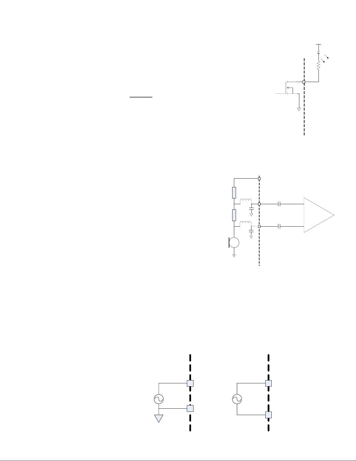
2. LED drive pins are open drain outputs and hence the external circuit
to the right should be used.
The voltage on the module pad should be maintained below 0.5V
in which case the Ron of the FET is around 20Ω. Provided that this
condition is met, then the current owing through the diode is:
F
led
I
VDD - V
=
R + 20
Where VF is the forward bias voltage of the LED.
3. The speaker output is capable of driving loads with a minimum
impedance of 16Ω directly.
4. The audio inputs can operate in either line input mode or microphone
mode. The input circuit has a two stage amplier – the rst stage
provides a xed 24dB gain and the second a variable gain of
between -3dB and 18dB. If an input gain of less than 24dB is selected,
then the rst stage is switched out and the module is operating in line
input mode.
When operating in microphone mode the
microphone should be biased as follows:
7
www.lairdtech.com
The input impedance on the microphone inputs (in microphone mode) is typically 6kΩ. In order to
maintain the regulation on the MIC_BIAS pin, the current drawn must be in the range 0.2 – 1.23mA.
If the microphone draws less current than this, then an additional resistor to ground must be added to
pre-load the microphone output. The audio input is designed for use with inputs of between 1μA
and 10μA at 94dB SPL. If the biasing resistors are set to 1kΩ, this implies a microphone with a
sensitivity in the range -40dBV to -60dBV.
The low pass lter elements formed by the inductor and capacitor are required to eliminate RF pick
up on the microphone inputs and should be placed as close to the module as possible.
When operating in line input mode, the input can be connected directly to the module input pins
in either single or double ended conguration as follows:
Laird Technologies
Page 8

BTM510/511
Bluetooth® Multimedia Module
OPERATING
PARAMETERS
OPERATING PARAMETERS
RECOMMENDED OPERATING CONDITIONS
Operating Condition Min Max
VDD_USB
(USB compatibility not required)
VDD_USB
(USB compatibility required)
VDD_IO 1.7 3.3
VDD_IN 3.0 3.6
1.7 3.6
3.1 3.6
VOLTAGE SPECIFICATIONS
LOGIC LEVELS (VUSB)
Input Voltage Levels Min Typ Max
V
ih
V
il
Output Voltage Levels
(Iout = -4mA) 0.75VDD_USB VDD_USB
V
oh
(Iout = 4mA) 0 0.125
V
ol
LOGIC LEVELS (VIO)
Input Voltage Levels Min Typ Max
V
ih
V
il
Output Voltage Levels
(Iout = -4mA) 0.75VDD_IO VDD_IO
V
oh
(Iout = 4mA) 0 0.125
V
ol
0.625VDD_USB VDD_USB+0.3
-0.3 0.25VDD_USB
0.625VDD_IO VDD_IO+0.3
-0.3 0.25VDD_IO
LOGIC LEVELS (VUSB – USB TERMINALS D+, D-)
Input Voltage Levels Min Typ Max
V
ih
V
il
Output Voltage Levels (to correctly terminated USB cable)
2.8 VDD_USB
V
oh
V
ol
0.7VDD_USB
0.3VDD_USB
0 0.2
NOTES FOR PCB LAYOUT:
1. The RF output pin must be matched to a 50Ω strip-line or coplanar waveguide on the antenna-less version (BTM510).
2. Ensure that there are no exposed conductors under the module to avoid shorts to the test points on the module underside.
3. ThePCBfootprintisprovidedforguidanceonly.UsersmaywishtomodifythePCBlanddimensionstosuittheirspecic
manufacturing or process.
www.lairdtech.com
8
Laird Technologies
Page 9

BTM510/511
Bluetooth® Multimedia Module
AT COMMAND SET
REFERENCE
INTRODUCTION
This document describes the protocol used to control and congure the BTM Bluetooth device.
The protocol is similar to the industry standard Hayes AT protocol used in telephony modems which is
appropriate for cable replacement scenarios, as both types of devices are connection oriented.
Just like telephony modems, Laird Technologies’ devices power up in an unconnected state and will only
respond via the serial interface. In this state, the device will not even respond to Bluetooth inquiries. Then,
just like controlling a modem, the host can issue AT commands which map to various Bluetooth activities.
The conguration of the device can be saved, so that on a subsequent power up the device is discoverable
or automatically connects.
The device has a serial interface which can be congured for baud rates from 1200 up to 921600 (default
setting is 9600) and an RF communications end point. The latter has a concept of connected and unconnected
modes and the former will have a concept of command and data modes. This leads to the matrix of states
shown below.
RF Unconnected RF Connected
Local Command Mode OK OK
Remote Command Mode ILLEGAL OK
Data Mode ILLEGAL OK
The combinations ‘Data and RF Unconnected Mode’ and ‘Remote Command and RF Unconnected Mode’
do not make sense and will be ignored.
Navigation between these states is done using the AT commands which are described in detail in
subsequent sections.
www.lairdtech.com
9
Laird Technologies
Page 10

BTM510/511
Bluetooth® Multimedia Module
AT COMMAND SET
REFERENCE
GLOSSARY OF TERMS
Description
A2DP : Advanced Audio Distribution Prole
ACL : Asynchronous Connection-Oriented Link
ADC : Analogue to Digital Converter
AGHFP : Audio Gateway Hands-Free Prole
AT : Command prex, ‘Attention’
AVRCP : Audio/Video Remote Control Prole
BISM : Bluetooth Intelligent Serial Module
CoD : Class Of Device (also referred to as “device class”)
Codec : Device capable of encoding / decoding an analogue / digital signal
DAC : Digital to Analogue Converter
DSP : Digital Signal Processor
DUN : Dial-Up Network Prole
EIR : Extended Inquiry Response
eSCO : Enhanced Synchronous Connection Oriented Link (used for Audio)
FTP : File Transfer Prole
GOEP : Generic Object Access Exchange Prole
GPIO : General Purpose Input Output
HF : Hands-free Role of Hands-free Prole (“Hands-free Unit”)
HFG : Audio Gateway Role of Hands-free Prole (“Hands-free Gateway”)
HFP : Hands Free Prole
HID : Human Interface Device Prole
HS : Headset Role of Headset Prole (“Headset”)
HSG : Audio Gateway Role of Headset Prole (“Headset Gateway”)
HSP : Headset Prole
I/O (IO) : Input/Output
Mic : Microphone
MITM : Man In The Middle
OPP : Object Push Prole
PBAP : Phone Book Access Prole
PT : PASS THROUGH Command
PWM : Pulse Width Modulation
SBC : Sub Band Codec
SCO : Synchronous Connection Oriented Link (used for Audio)
SLC : Service Level Connection
SPP : Serial Port Prole
SSO : Serial Stream Oriented
SSP : Secure Simple Pairing
SUI : SUBUNIT INFO Command
Sxxx : S-Register No. xxx
TDL : Trusted Device List
UART : Universal Asynchronous Receiver / Transmitter
UI : UNIT INFO Command
www.lairdtech.com
10
Laird Technologies
Page 11

BTM510/511
Bluetooth® Multimedia Module
AT COMMAND SET
REFERENCE
OVERVIEW OF THE BTM PRODUCT FAMILY
BTM410 / BTM411
Chipset CSR BC4-Ext
Bluetooth version 2.1
Features SSP, EIR, SCO (1), eSCO (1)
Proles SPP
(1) external codec required
BTM510 / BTM511
Chipset CSR BC5MM-Ext
Bluetooth version 2.1
Features SSP, EIR, SCO, eSCO
Proles SPP, A2DP, AVRCP,HSP,HFP,DUN(DT)
BTM520 / BTM521
Chipset CSR BC5MM-Ext
Bluetooth version 2.1
Features SSP, EIR, SCO, eSCO
Proles SPP, A2DP, AVRCP,HSP,HFP,DUN(DT)
www.lairdtech.com
11
Laird Technologies
Page 12

BTM510/511
Bluetooth® Multimedia Module
AT COMMAND SET
REFERENCE
BTM - AT COMMAND SET
This section describes the AT Command Set for a BTM module. This section is structured in functional
groups of AT commands related to module conguration, Bluetooth proles, hardware units and
miscellaneous purposes.
Assumptions
1. All commands are terminated by the carriage return character 0x0D, which is represented by the string
<cr> in descriptions below this cannot be changed.
2. All responses from the BTM device have carriage return and linefeed characters preceding and
appending the response. These dual character sequences have the values 0x0D and 0x0A respectively
and shall be represented by the string <cr,lf>.
3. All Bluetooth addresses are represented by a xed 12 digit hexadecimal string, case insensitive.
4. All Bluetooth Device Class codes are represented by a xed six digit hexadecimal string, case insensitive.
5. All prole specic commands are identied by the prex shown in Table 3.1
Prole Term AT-Command Prex
Serial Port Prole SPP AT+SP…
Advanced Audio Distribution Prole A2DP AT+AP…
Audio/Video Remote Control Prole AVRCP AT+AV…
Headset Prole HSP AT+HS…
Hands-Free Prole HFP AT+HF…
Dial-Up Network Prole DUN AT+DU…
Table 3.1: AT Command prex for proles
Command Syntax
The following syntax is employed throughout this document to describe optional or mandatory parameters for
AT commands.
<bd_addr> A 12 character Bluetooth address consisting of ASCII characters ‘0’ to ‘9’, ‘A’ to ‘F’ and ‘a’ to ‘f’.
<devclass> A six character Bluetooth device class consisting of ASCII characters ‘0’ to ‘9’, ‘A’ to ‘F’ and ‘a’ to ‘f’.
n A positive integer value.
m An integer value which could be positive or negative, which can be entered as a decimal value or
<string> A string delimited by double quotes, e.g., “Hello World”. The “ character MUST be supplied as delimiters.
<uuid> A four character UUID number consisting of ASCII characters ‘0’ to ‘9’, ‘A’ to ‘F’ and ‘a’ to ‘f’.
in hexadecimal if preceded by the ‘$’ character, e.g., the value 1234 can also be entered as $4D2.
General AT Commands
1. AT
Used to check the module is available.
Response: <cr,lf>OK<cr,lf>
2. ATEn {Enable/Disable Echo}
This command enables or disables the echo of characters to the screen. A valid parameter value will be
written to S Register 506.
E0 … Disable echo.
E1 … Enable echo.
All other values of n will generate an error.
Response: <cr,lf>OK<cr,lf>
Or
Response: <cr,lf>ERROR nn<cr,lf>
www.lairdtech.com
12
Laird Technologies
Page 13

BTM510/511
Bluetooth® Multimedia Module
AT COMMAND SET
REFERENCE
3. ATZ<n> {Hardware Reset and Emerge Into Boot Mode ‘n’}
Forces the device through a hardware reset which means it will eventually come alive in the local
command and unconnected mode. This allows changes to the non-volatile memory to take effect.
The module will issue an OK response after the reset is complete and it is ready to receive commands
once again.
ATZ and ATZ0 signify reset and emerge into the current boot mode (see command ATI14). ATZ1 to ATZ4
instructs the module to reset and then emerge into the appropriate boot mode. Note that S Register 103
species the boot mode from cold.
Boot modes are required to congure some low level device settings which cannot be congured by
S registers and AT commands. Currently there are predened settings dening the PCM data format
to be used with certain codec ICs (applies mainly to BC04).
Response after reset: <cr,lf>OK<cr,lf>
4. AT+BTC<devclass
This command is used to set the device class code which will be sent in subsequent inquiry responses.
It can be read back using the AT+BTC? Command, as described below.
<devclass> is a six digit hexadecimal number derived as per “Bluetooth Assigned Numbers” [8].
The 24 bits are made of four elds briey described as follows (bit 0 corresponds to the least
signicant bit):-
Bits 0-1: Format Type. This eld currently only has a value of 00 (i.e.,
Bits 2-7: Minor Device Class: The value of these six bits is interpreted
Bits 8-12: Major Device Class: Five bits, refer to Figure 1 and Table 3 in
Bits 13-23: Major Service Class: 11 bit eld, used as a mask to dene
> {Set Device Class Code Temporarily}
hex
format type 1).
differently based on the Major Device Class stored in the next
ve bits.
“Bluetooth Assigned Numbers” [8].
service classes, refer to Figure 1 and Table 2 in “Bluetooth
Assigned Numbers” [8].
www.lairdtech.com
13
Laird Technologies devices do not map to any predened Major Service Class or Major Device Class and
so the default devclass as shipped is 001F00, which means no Major Service Class and “Unclassied”
Major Device class.
Other examples of device class codes are follows:
Code (Hexadecimal) Name Major Service Major Device Minor Device
0x001F00 Unclassied None Unclassied n/a
0x200404 Headset Audio Audio Headset
There is a tool available in the Internet for creating a particular device class code: refer to [9].
A device class set by AT+BTC becomes visible immediately but will be lost on next power cycle.
Response: <cr,lf>OK<cr,lf>
Or for an invalid <devclass> value (usually a value which is not 6 hexadecimal characters long):
Response: <cr,lf>ERROR 08<cr,lf>
5. ATS515=<devclass
S Register 515 is used to set the device class code permanently. Use AT&W to save the setting to
non-volatile memory. The new value will become visible on next power cycle which can be initiated
by ATZ. Refer to number 4 for more information about the device class code.
Response: <cr,lf>OK<cr,lf>
6. AT+BTC? {Read Device Class Code}
This command is used to read the current device class code.
Response: <cr,lf>123456
<cr,lf>OK<cr,lf>
> {Set Device Class Code Permanently}
hex
Laird Technologies
Page 14

BTM510/511
Bluetooth® Multimedia Module
AT COMMAND SET
REFERENCE
7. AT+BTF=”<string>” {Set Friendly Name Temporarily}
This sets the friendly name of this device as seen by other devices. The new name becomes immediately
visible. Any name set by this command will be lost on next power cycle.
Please refer to S register 593 (Table 4.1) too.
Response: <cr,lf>OK<cr,lf>
8. AT+BTN=”<string>” {Set Friendly Name Permanently}
This sets the default friendly name of this device as seen by other devices. It will be stored in non-volatile
memory. The new name will become visible to other devices on next power cycle. Use AT+BTF to make
the name visible immediately. Use AT+BTN? to read it back. An empty string (“”) will delete the string
from non-volatile memory which will force the default name to be used which is “Laird BTM 789012”.
The digits in the default friendly name represent the last six digits of the local Bluetooth address.
Please refer to S register 593 (Table 4.1) too. If a new value of S593 needs to be retained permanently,
save it to non-volatile memory by “AT&W”.
Response: <cr,lf>OK<cr,lf>
9. AT+BTN? {Read Friendly Name from Non-volatile Memory}
Read the default friendly name from non-volatile memory.
Response: <cr,lf>”My Friendly Name”<cr,lf>
<cr,lf>OK<cr,lf>
10. AT+BTF<bd_addr> {Get Remote Friendly Name}
This command gets the remote friendly name of the peer specied.
Response: <cr,lf><bd_addr>,”Friendly Name”
<cr,lf>OK<cr,lf>
11. AT+BTP {Make Device Discoverable and Connectable }
Make the device discoverable and connectable and wait for a connection from any device.
The setting remains valid until next reset or power cycle (unless not changed by any other AT command
subsequently). For permanent discoverable/connectable settings, please refer to S Register 512.
Response: <cr,lf>OK<cr,lf>
12. AT+BTQ {Make Device Discoverable}
Make the device discoverable but not connectable. Being discoverable implies that this device will
respond to inquiries from other devices (inquiry scans enabled).
The setting remains valid until next reset or power cycle (unless not changed by any other AT command
subsequently). For permanent discoverable/connectable settings, please refer to S Register 512.
Use AT+BTX to make the device not discoverable.
Response: <cr,lf>OK<cr,lf>
13. AT+BTG {Make Device Connectable}
Make the device connectable but not discoverable and wait for a connection from any device.
The setting remains valid until next reset or power cycle (unless not changed by any other AT command
subsequently). For permanent discoverable/connectable settings, please refer to S Register 512.
Response: <cr,lf>OK<cr,lf>
www.lairdtech.com
14
Laird Technologies
Page 15

BTM510/511
Bluetooth® Multimedia Module
AT COMMAND SET
REFERENCE
14. AT+BTV<bd_addr>,<uuid> {SDP Query for Service }
This command is used to interrogate the SDP database of the peer device <bd_addr> for the service
<uuid>. It results in an ACL connection and then an SDP transaction.
If the <uuid> service is present then
Response: <cr,lf>0
<cr,lf>OK<cr,lf>
If the <uuid> service is not present then
Response: <cr,lf>1
<cr,lf>OK<cr,lf>
If the device < bd_addr > cannot be reached, or is in non-connectable mode then
Response: <cr,lf>2
<cr,lf>OK<cr,lf>
If the SDP database is corrupt or invalid then
Response: <cr,lf>3
<cr,lf>OK<cr,lf>
If the device is not in idle mode then
Response: <cr,lf>4
<cr,lf>OK<cr,lf>
and in this case, the command AT+BTX may put the device into the correct idle mode.
15. ATIn {Information}
This will return the information about the Laird Technologies device and its status. Please refer to
Table 4.2 (Appendix) for a complete list of supported ATIn parameters.
For recognized values of n:
Response: <cr,lf>As Appropriate<cr,lf>OK<cr,lf>
For unrecognized values of n.
Response: <cr,lf>Laird Technologies Inc, UK, (c)2009<cr,lf>
AT Commands for S Registers
As with modems, the Bluetooth module employs a concept of registers which are used to store parameters,
such as escape sequence character, inquiry delay time, etc.
For a list of general S registers please refer to page 17 and Table 4.1.
S registers associated with a particular prole or specic functions, are described in the appropriate prole
section of this document.
The following AT commands allow the manipulation of S registers.
1. ATSn=m {Set S Register}
The value part ‘m’ can be entered as decimal or hexadecimal. A hexadecimal value is specied via a ‘$’
leading character. For example $1234 is a hexadecimal number.
When S register values are changed, the changes are not stored in non-volatile memory UNTIL the
AT&W command is used. Note that AT&W does not affect S registers 520 to 525 or 1000 to 1010
as they are updated in non-volatile memory when the command is received.
2. ATSn? {Read S Register Value}
This will return the current value of register n.
For recognized values of n
Response: <cr,lf>As Appropriate<cr,lf>OK<cr,lf>
For unrecognized values of n
Response: <cr,lf>ERROR nn<cr,lf>
www.lairdtech.com
15
Laird Technologies
Page 16

BTM510/511
Bluetooth® Multimedia Module
AT COMMAND SET
REFERENCE
3. ATSn=? {Read S Register – Valid Range}
This will return the valid range of values for register n.
For recognized values of n
Response: <cr,lf>Sn:(nnnn..mmmm)<cr,lf>OK<cr,lf>
For unrecognized values of n
Response: <cr,lf>ERROR nn<cr,lf>
4. AT&Fn {Set S Register Defaults}
This command will only work when the device is in local command and unconnected mode.
Depending on the value of ‘n’, it installs S Register values appropriate for various power modes
ranging from minimum power consumption to maximum.
Legal values of ‘n’ are as per the following table. All other values of n will generate a syntax error
response. If ‘n’ is not specied then a default value of 0 is assumed where the baud rate is
NOT changed.
&F0 (Default) Medium power consumption, UART baud rate unchanged
&F1 Minimum power consumption, UART baud rate set to 9600
&F2 Minimum power consumption, UART baud rate set to 38400
&F3 Minimum power consumption, UART baud rate set to 115200
&F4 Medium power consumption, UART baud rate set to 115200
&F5 Maximum power consumption, UART baud rate set to 115200
The new values are NOT updated in non-volatile memory until the AT&W command is sent to
the device.
Response: <cr,lf>OK<cr,lf>
Or
Response: <cr,lf>ERROR nn<cr,lf>
5. AT&F* {Clear Non-Volatile Memory}
The AT&F* variant of the command installs values in S registers as per command AT&F4 and then
all other user parameters in non-volatile memory are erased. This means that the trusted device
database is cleared, and so are parameters related to the following commands: AT+BTR, AT+BTN,
AT+BTS.
Response: <cr,lf>OK<cr,lf>
Or
Response: <cr,lf>ERROR nn<cr,lf>
6. AT&F+ {Clear Non-Volatile Memory}
This command erases all user parameters in non-volatile memory except S Registers 520 to 525.
This means that the trusted device database is cleared, and so are parameters related to the following
commands: AT+BTR, AT+BTN, AT+BTS.
Response: <cr,lf>OK<cr,lf>
Or
Response: <cr,lf>ERROR nn<cr,lf>
www.lairdtech.com
16
7. AT&W {Write S Registers to Non-Volatile Memory}
Writes current S Register values to non-volatile memory so that they are retained over a power cycle.
Response: <cr,lf>OK<cr,lf>
Or
Response: <cr,lf>ERROR nn<cr,lf>
Laird Technologies
Page 17

BTM510/511
Bluetooth® Multimedia Module
AT COMMAND SET
REFERENCE
General S Registers
Please refer to Appendix, Table 4.1 for a list of supported S Registers.
The main purpose of S Registers is to make the device conguration persistent. All S Registers can be saved to
non-volatile memory by AT&W.
In some cases, an AT command and an S register exist for one and the same setting. In the majority of those
cases the AT command’s setting will be lost on next power cycle whereas the S register can be saved and is still
available after power cycle. This rule applies to many but not to all of those cases.
AT Commands for Inquiry
1. AT+BTI<devclass> { Inquire}
This will make the device perform an inquiry for delay seconds and max number of unique responses,
where delay is dened by S register 517 and max is specied by S register 518.
The <devclass> is an optional parameter where the value species either a six digit device class code or
a two digit major device class. If it is not specied, the value is taken from S register 516.
When <devclass> is six hexadecimal characters long, it species an AND mask which is used to lter
inquiry responses. When <devclass> is two hexadecimal characters long, it forces the inquiry to lter
responses to devices that match their major device class code to this value – which can only be in
the range 00 to 1F.
The response format to AT+BTI is dened by S Register 330 by bitmask. This is device address, device
class, friendly name, receiver strength indicator and extended inquiry data. Please refer to Figure 3.1
and Table 3.2.
For S330=1:
Response: <cr,lf>12346789012
<cr,lf>12345678914
<cr,lf>OK<cr,lf>
A Bluetooth inquiry process is such that for a single inquiry request a device could respond many times.
To ensure that an address is sent to the host only once for a particular AT+BTI, an array of addresses is
created at the start of each AT+BTI and is lled as responses come in. This array of addresses is stored
in dynamic memory and as such if the memory allocation fails then the inquiry procedure is aborted and
in that case an error response is sent to the host. To clarify, a single AT+BTI will never return the same
Bluetooth address more than once. But as long as the responding device is active, all AT+BTI commands
will always return it.
As the inquiry process is driven by randomness, it is not guaranteed that each discoverable device is
always found on the rst attempt. Sometimes more than one inquiry processes might be necessary
to nd a particular device. The probability also depends on the inquiry scanning intervals of the device
being searched for.
The inquiry process can be sped up if the friendly name is not required (ag not set in S330) as part of
the inquiry response or if a <dev_class> lter is used.
www.lairdtech.com
17
Bit 7 6 5 4 3 2 1 0
Reserved for future usage EIRD RSSI FN COD ADR
Default 0 0 0 0 0 0 0 1
Figure 3.1: S Register 330 controlling inquiry response format
Field Description
0 – ADR 1 – display Bluetooth device address on inquiry result
0 – do not display Bluetooth device address on inquiry result; if any further bit is set, a comma is inserted as
separator
1 – COD 1 – display class of device on inquiry result
0 – do not display class of device on inquiry result; if any further bit is set, a comma is inserted as separator
2 – FN 1 – display friendly name on inquiry result
0 – do not display friendly name on inquiry result; if any further bit is set, a comma is inserted as separator
3 – RSSI 1 – display RSSI value on inquiry result
0 – do not display RSSI value on inquiry result; if any further bit is set, a comma is inserted as separator
4 – EIRD 1 – display eird on inquiry result
0 – do not display eird on inquiry result
Table 3.2: Field Descriptions for S Register 330
Laird Technologies
Page 18

BTM510/511
Bluetooth® Multimedia Module
AT COMMAND SET
REFERENCE
Inquiry Response Format
The format of an inquiry result will be:
<cr,lf><bd_addr>,<dev_class>,<friendly_name>,<rssi>,<eir_data><cr,lf>
<bd_addr> = 12 digit, hexadecimal;
<dev_class> = six digit, hexadecimal;
<friendly_name> = printable ASCII character, enclosed by ‘ “ ‘
<rssi> = signed two digits decimal
<eir_data> = printable ASCII character whenever possible, otherwise a byte is displayed as ¬2 digit
hexadecimal with preceding ‘\’, enclosed by ‘ “ ‘
For example the data block 01 41 42 43 44 02 03 45 46 04 0A 0D will be presented as
“\01ABCD\02\03456\04\0A\0D”
No validation is performed on incoming EIR data.
If a higher signicant ag is set and a lower signicant bit is not set in S 330, for each disabled item
a comma is printed.
Example: S330 = 9 (ADDR enabled, COD and FN disabled, RSSI enabled)
Inquiry Response:
<cr,lf>123456789012,,,-54
<cr,lf>123456789014,,,-54
<cr,lf>OK<cr,lf>
2. AT+BTIV<devclass> { Inquire }
As per AT+BTI but the response comprises for all inquiry responses:
1. the Bluetooth device address
2. device class code
S register 330 is not referenced.
www.lairdtech.com
18
3. AT+BTIN<devclass> { Inquire }
As per AT+BTI but the response comprises for all inquiry responses:
1. the Bluetooth device address
2. device class code
3. friendly name
S register 330 is not referenced.
4. AT+BTIR<devclass> { Inquire }
As per AT+BTI but the response comprises for all inquiry responses:
1. the Bluetooth device address
2. device class code
3. friendly name
4. rssi (receiver signal strength indicator)
S register 330 is not referenced.
5. AT+BTIE<devclass> { Inquire }
As per AT+BTI but the response comprises for all inquiry responses:
1. the Bluetooth device address
2. device class code
3. friendly name
4. rssi (receiver signal strength indicator)
5. extended inquiry data
S register 330 is not referenced.
Laird Technologies
Page 19

BTM510/511
Bluetooth® Multimedia Module
AT COMMAND SET
REFERENCE
6. AT+BTE=”<EIR-Data>” {Set Up Outgoing EIR Data}
This command sets up outgoing EIR (extended inquiry response) data.
Format: <EIR-Data> = printable ASCII character whenever possible, otherwise a two digit hexadecimal
with preceding ‘\’ presenting one byte. Please note that the given data is written to baseband as it
is (raw data) and no checks on the data format is performed. Hence, the user is responsible for writing
data that corresponds to the extended inquiry response data format as described in the Bluetooth
Specication Version 2.1 + EDR [1], vol3, Part C – Generic Access Prole, 8 Extended Inquiry Response
Data Format (page 1305 in the .pdf-le).
Response: <cr,lf>OK<cr,lf>
7. AT+BTE? {Query Outgoing EIR Data}
This command prints the outgoing EIR data that is currently set up
Response:
<cr,lf>
<EIR-Data>
<cr,lf>OK<cr,lf>
Secure Simple Pairing (SSP)
Secure Simple Pairing (SSP) has been introduced since Bluetooth 2.1 + EDR. It aims to increase the security
provided by a Bluetooth link whilst making the pairing process more user friendly.
There are white papers about SSP available through the Internet (provided by the Bluetooth SIG and other companies), explaining the mechanisms and backgrounds of SSP. They can be found by searching the Internet for,
e.g., “Bluetooth Secure Simple Pairing”. Please familiarize with those documents to get a better understanding
of SSP and the following settings.
1. Security Level (S320)
The security level is dened in the BT2.1+EDR specication [1], vol3, Generic Access Prole (Table 5.7).
There are 4 Levels providing different levels of security:
Security Level Characteristics Comment
Level 3 • MITM protection (MITM = “Man in the
Middle” attack)
• Encryption
• User interaction
Level 2 • No MITM protection
• Encryption
Level 1 • No MITM protection
• (No) Encryption (1)
• Minimal user interaction
Level 0 • No MITM protection
• No Encryption
• Minimal user interaction
(1) Although encryption is not necessary for security level 1, encryption will always be enabled
because this specication mandates encryption for all services other than SDP (service discovery).
Table 3.3: Security Levels
The security level is dened by S Register 320 and is referenced at boot time only. Hence the register
must be saved by “AT&W “ and the module must be power cycled (or “ATZ”) subsequently.
S320 = 3 will overwrite the setting of S Register 322 (enable MITM).
The security level will remain the same until next power cycle and is valid for all proles and services
of the module. For SDP (service discovery prole), security level 0 is always assigned internally.
High security
Medium Security
Low Security
Permitted only for service
discovery
www.lairdtech.com
19
Laird Technologies
Page 20

BTM510/511
Bluetooth® Multimedia Module
AT COMMAND SET
REFERENCE
2. IO-Capability (S321)
S-Register 321 denes the IO-capability of the device. The setting is used for IO-capability negotiations
prior to SSP in order to identify whether the IO-capabilities of both devices are sufcient for MITM
protection (if required). Table 3.4 lists possible values.
S321 IO-Capability Comment
0 Display only The device has the capability to display or communicate a
six digit decimal number.
1 Display yes no The device has the capability to display or communicate
a six digit decimal number and at least two buttons that
can be easily mapped to ‘yes’ and ’no’ or a mechanism
whereby the user can indicate either ‘yes’ or ‘no’ (e.g.,
pressing a button within a certain time limit).
2 Keyboard only The device has a numeric keyboard that can input
numbers ‘0’ through ‘9’ and a conrmation. The device
has also at least two buttons that can be easily mapped
to ‘yes’ and ’no’ or a mechanism whereby the user can
indicate either ‘yes’ or ‘no’ (e.g., pressing a button within
a certain time limit).
3 No input no output The device does not have the ability to indicate ‘yes’ or
‘no’, and the device does not have the ability to display or
communicate a 6 digit decimal number.
4 Reject IO-Cap requests IO-capability requests prior to SSP are rejected.
Table 3.4: IO capabilities
3. Force Man-In-The-Middle Protection (MITM, S322)
Protection against MITM-attacks can be enabled by S332. This S-Register only applies if the security
level (S320) is less than 3. In case of security level (S320) = 3, MITM protection is always enabled and
this S 322 is ignored.
A new value written to S322 applies immediately. No power cycle is required.
A link key created with MITM protection is named “authenticated link key”.
A link key created without MITM protection is named “unauthenticated link key”.
4. Disable Legacy Pairing (S323)
If the remote device is a legacy device (BT2.0 or earlier), legacy pairing with usage of PIN codes will
be initiated. Legacy Pairing can be disabled by S-Register 323 = 1. Then pairing with legacy devices
will always fail.
5. SSP Timeout (S324)
The SSP timeout [s] is dened by S-Register 324. The timeout must be at least 60s to meet the BT
specication requirements [1]. This time is required to be sufcient for the user to compare or read
and input a 6 digit number. A time of 90 seconds is recommended which is the default value.
6. SSP Input Commands
Table 3.5 lists all AT commands related to SSP input operations.
AT Command Operation Comment
AT+BTBY Accept pairing request Representing ‘yes’ input
AT+BTBN Reject pairing request Representing ‘no’ input
AT+BTB012345 Enter six digit passkey displayed by remote device Representing keyboard input
Table 3.5: SSP Input commands
www.lairdtech.com
20
Laird Technologies
Page 21

BTM510/511
Bluetooth® Multimedia Module
AT COMMAND SET
REFERENCE
7. AT+BTW<bd_addr> {Initiate SSP}
This command initiates secure simple pairing (dedicated bonding) with a device whose Bluetooth
address is <bd_addr>. The correct term for this command’s action with respect to the Bluetooth
specication 2.1+EDR [1] is “Dedicated Bonding”.
Dedicated bonding means the exchange of link keys (pairing) without creating a connection to a
particular prole or service immediately.
The remote device must be a Bluetooth 2.1 device, otherwise (BT2.0 or earlier) legacy pairing will occur
automatically if S323=0. For legacy pairing please refer to page 23.
The “OK” response is sent immediately on receipt of the AT+BTW command. Depending on the
combination of IO-capabilities of both devices, one of the asynchronous messages from Table 3.7
might appear during the pairing process. Please refer to that table for the required actions.
On pairing completion, an unsolicited message in the form PAIR n <bd_addr> will be sent to the host.
8. S Registers for Secure Simple Pairing
The following table lists all S Registers for Secure Simple Pairing. For the registers’ details please refer
to their descriptions above.
Register Default Range Comment
S320 2 1..3 Security Level: see [1], vol3, Generic Access Prole - Table 5.7
needs subsequent ‘AT&W’ and power cycle to take effect
value = 3 overwrites S322
S321 1 0..4 Set IO capability:
0 – display only
1 – display yes no
2 – keyboard only
3 – no input no output
4 – reject IO-cap requests
S322 0 0..1 Force man-in-the-middle-protection (MITM):
0 – disabled
1 – enabled
referenced only if security level (S320) < 3
S323 0 0..1 Disable legacy (pre-BT2.1) Pairing:
0 – legacy pairing enabled
1 – legacy pairing disabled
S324 90 1..255 Secure Simple Pairing timeout in s
This value must be at least 60 in order to meet the recom-
mendation of BT2.1 specication
Table 3.6: S-Registers for Secure Simple Pairing (SSP)
www.lairdtech.com
21
Laird Technologies
Page 22

BTM510/511
Bluetooth® Multimedia Module
AT COMMAND SET
REFERENCE
9. Asynchronous SSP Messages
Table 3.7 lists asynchronous messages which occur if MITM is enabled. The actually sent message
depends on the combination of the IO capabilities of both ends. The combination of IO capabilities
of both devices can also be insufcient for MITM protection. In that case the pairing will fail (PAIR 2
<BdAddr>). Please refer Table 5.6 in BT2.1+EDR specication [1], vol3, Generic Access Prole for
sufcient combinations of IO-capabilities for MITM (=authenticated link key).
Message Action / Comment
PAIR ? <BdAddr>,”<friendlyname>”,<Passkey>
Example:
PAIR ? 0016A4000002,”Laird BTM
000002”,863611
PASSKEY ? <BdAddr>,”<friendlyname>”
Example:
PASSKEY ? 0016A4000001,”Laird BTM 000001”
PAIR N <BdAddr>,”<friendlyname>”,<Passkey>
Example:
PASSKEY N 0016A4000002,”Laird BTM
000002”,164585
PAIR 0 <BdAddr> <nn> Successfully paired with device of <BdAddr>.
PAIR 1 <BdAddr> Pairing timeout
PAIR 2 <BdAddr> Pairing failed
PAIR 3 <BdAddr> Pairing failed (too many repeat attempts)
PAIR 4 <BdAddr> Pairing rejected by remote device
PAIR 5 <BdAddr> Pairing failed (unit keys not supported)
PAIR 6 <BdAddr> Pairing failed (SSP not supported)
PAIR 7 <BdAddr> Pairing failed (already busy with pairing)
(1) If both devices have a “KeyboardOnly” capability, no pass key can be displayed. In that case, the
user is required to invent and enter the identical 6 digit numeric passkey at both ends.
Table 3.7: Asynchronous messages for SSP
Passkey compare request:
Expecting the user to compare the passkey
displayed on both ends and to conrm a
match by “AT+BTBY” at both ends or reject by
“AT+BTBN” if passkey does not match.
Passkey request:
Expecting the user to enter the passkey
displayed by the remote device.
Use AT+BTB<passkey>,
example: AT+BTB012345 *see(1) below
Passkey notication:
Display BdAddr, friendly name and passkey to
user.
Expecting the user to enter the passkey from
this message at the remote device’s numeric
keyboard.
<nn> (optional) indicates the status of automatic storage to trusted device list. Value 0 =
success; settings controlled by S325 to S328.
Please refer to section 2.3, page 82.
www.lairdtech.com
22
10. Known SSP Issues
a.) General Bonding (automatic pairing on link setup if devices have not been paired previously) does
not work with legacy devices (BT2.0 and earlier). If the remote device is BT2.0 or earlier, initiate
dedicated bonding (AT+BTW<BdAddr>) prior to connection establishment.
b.) Outgoing General Bonding (automatic pairing on link setup if devices have not been paired
previously) with MITM does not work with two BTM devices, because any UART input on the
initiating device is not accepted until the link has been established. Workaround: initiate dedicated
bonding (AT+BTW<BdAddr>) prior to connection establishment.
c.) If the link key of previously paired devices is not available any more in the remote device but still
available in the trusted device list (TDL) of the local device (query by AT+BTT?), pairing will fail. In that
case remove the device address from the local TDL using AT+BTD<BdAddr> and reinitiate pairing
from the local device (AT+BTW<Bd_addr>).
Laird Technologies
Page 23

BTM510/511
Bluetooth® Multimedia Module
AT COMMAND SET
REFERENCE
AT Commands for Legacy Pairing
1. AT+BTW<bd_addr> {Initiate Pairing}
Provided the remote device is a Bluetooth 2.0 device or earlier and legacy pairing is not disabled
(S323 = 0), this command is used to initiate legacy pairing with the device with <bd_addr>.
Legacy pairing refers to the mechanism of entering an identical PIN key on both ends.
If the PIN is required (if not set earlier by AT+BTK=”<PIN>”), asynchronous indications will be sent
to the host in the form PIN? <bd_addr> where the address conrms the device with which the pairing
is to be performed. To supply a PIN, use the AT+BTK command.
For a successful pairing, the link key is stored in a volatile cache which is overwritten every time a
new pairing is initiated using this command. If S register 325=1, the link key is automatically saved
to the non-volatile trusted device list. Otherwise (S325=0) the link key can be added to the trusted
device list by AT+BTT. Please refer to below under AT Commands managing Trusted Devices for
further AT commands related to trusted device list.
The “OK” response is sent immediately on receipt of the AT+BTW command. On pairing completion,
an unsolicited message will be sent to the host which will be in the form PAIR n <bd_addr>.
If AT+BTI or AT+BTP or AT+BTG or AT+BTQ or ATD is issued between the AT+BTW command and
the subsequent PAIR asynchronous response, then an ERROR response will be sent to those commands
as the device is not in a mode from where such commands can be actioned.
Response: <cr,lf>OK<cr,lf>
2. AT+BTK=”<string>” {Set Passkey}
This command is used to provide a PIN passkey. The PIN is stored in non-volatile memory for future use.
If this command is used as response to a “PIN? 12345678” asynchronous message, the PIN provided by
this command will not be stored in non-volatile memory.
Specifying an empty string deletes the PIN from the non-volatile memory. The string length must be in
the range 0 to 8, otherwise an error will be returned.
Response: <cr,lf>OK<cr,lf>
3. Legacy Pairing – Asynchronous Messages
PIN?
This response is sent to the host during a pairing negotiation.
The fully qualied string is PIN? 012345678901 where 012345678901 is the Bluetooth address of the
peer device. In response, the host must supply a pin code which is entered using the AT+BTK command.
If the peer does not supply the address in the message exchange, then the address is specied as
000000000000 – and the pairing will proceed as normal.
PAIR n <bd_addr>
This response is sent to the host on termination of a pairing process. If pairing was successful then
‘n’ = 0, if a timeout occurred then ‘n’=1 and for all other unsuccessful outcomes the value will be 2.
The parameter <bd_addr> is the address of the peer device if available.
PAIR 0 <bd_addr> MM
This response is sent to the host on termination of a successful pairing process. The optional MM is
sent only if the according S Register 325..328 is set to 1 to automatically save the link key (see Section
2, page 82). The value MM indicates the result of the save operation and a value of 00 implies success,
otherwise the value corresponds to an error code.
www.lairdtech.com
23
Laird Technologies
Page 24

BTM510/511
Bluetooth® Multimedia Module
AT COMMAND SET
REFERENCE
AT Commands Managing Trusted Devices
1. AT+BTT? {List Trusted Device}
This command is used to list the contents of the trusted device database. The link key is NOT displayed
so the response is as shown below. If the list is empty then just the OK response is sent otherwise an
OK is used to terminate the list. Use the command ATI6 to read the maximum size of the trusted
device database.
Response: <cr,lf>12346789012
<cr,lf>12345678913
<cr,lf>12345678914
<cr,lf>OK<cr,lf>
2. AT+BTT {Add Trusted Device}
This command is used to store the cached link key in the non-volatile database. If the database is full,
it will respond with an ERROR. If the device is already in the database, then the key is replaced. If the
link key cache is empty, that is, a pairing has not been performed since the device was powered, then
the response will be an ERROR.
Response: <cr,lf>OK<cr,lf>
Or
Response: <cr,lf>ERROR<cr,lf>
3. AT+BTD<bd_addr> {Remove Trusted Device}
This command is used to remove the specied device from the list of trusted devices in the non-volatile
database. If the device is not in the database, then the response will still be an OK.
Response: <cr,lf>OK<cr,lf>
www.lairdtech.com
24
4. AT+BTD* {Remove All Trusted Devices}
This command is used to remove all devices from the trusted device list (TDL) in the non-volatile
database. No conrmation will be asked for. So beware!!!
WARNING: If you make a connection, the link key gets cached in the underlying stack. So if you
subsequently delete the key using AT+BTD* and immediately request a connection to the same device,
then the connection will be established. To ensure this does not happen, send ATZ after the AT+BTD*.
Response: <cr,lf>OK<cr,lf>
5. AT+BTW? {List Cached Trusted Device}
This command is used to list the cached trusted device.
Response: <cr,lf>12346789012
<cr,lf>OK<cr,lf>
If the cache is empty the response is as follows.
Response: <cr,lf>OK<cr,lf>
AT Commands for Serial Stream Oriented Proles (SSO)
The Serial Port Prole (SSP) and the Dial-up Networking Prole (DUN) belong to the group of Serial Stream
Oriented proles (SSO).
When activated, an SSO prole claims one UART for its data stream and assumes all data at the UART to
be transmitted over or received from RF 1:1. Hence, as there is only one UART available on a BTM device,
the UART is not available for other proles, services or module control purposes.
One approach of managing data and control over UART is to congure local command mode with S531=3.
In this mode, incoming RF data is presented by the asynchronous message RX<string>. Outgoing data is sent
by ATX<string> or ATY<string>.
With this approach it is possible to manage several non-SSO connections (e.g., A2DP, AVRCP) and at
maximum one SSO connection (SSP or DUN). An attempt to connect a second SSO prole while already
one SSO connected will result in Error 65.
Any incoming connection request to an SSO prole will be rejected if one SSO is already connected.
The following section describes AT- commands related to SSO-proles.
Laird Technologies
Page 25

BTM510/511
Bluetooth® Multimedia Module
AT COMMAND SET
REFERENCE
1. ATX”<string>” {Send Data in Local Command and Connected Mode}
This command is used to send data to the remote device when in local command and connected mode.
The parameter <string> is any string not more than 29 characters long whereby a non-printable
character (\hh, see below) counts three characters. This restriction results from the maximum AT
command length which is 34 (query by ATI15). The difference of 5 is caused by “ATX” (three characters)
and the enclosing quotation marks (two characters).
If the maximum string length is exceeded, ERROR 05 (syntax error) will occur.
If a non-visual character is to be sent then insert the escape sequence \hh where hh are two
hexadecimal digits. The three character sequence \hh will be converted into a single byte before
transmission to the peer.
Response: <cr,lf>OK<cr,lf>
Or
<cr,lf>ERROR 05<cr,lf> (e.g. <string> too long)
2. ATY”<string>” {Send Data in Local Command and Connected Mode}
This command is similar to ATX in syntax and functionality, except that the string is only copied to
the output rf buffer. Only when an empty string is presented, all pending data in the output rf buffer
will be ushed out.
The parameter <string> is any string not more than 29 characters long whereby a non printable
character (\hh, see below) counts three characters. This restriction results from the maximum AT
command length which is 34 (query by ATI15). The difference of 5 is caused by “ATX” (three characters)
and the enclosing quotation marks (two characters).
If the maximum string length is exceeded, ERROR 05 (syntax error) will occur.
If a non-visual character is to be sent then insert the escape sequence \hh where hh are two
hexadecimal digits. The three character sequence \hh will be converted into a single byte before
transmission to the peer.
Response: <cr,lf>OK<cr,lf>
Or
<cr,lf>ERROR 05<cr,lf> (e.g. <string> too long)
3. ^^^ {Enter Local Command Mode}
When in data and connected mode and when S 507 is set to 0 or 1, the host can force the device into
a command and connected mode so that AT Commands can be issued to the device. The character in
this escape sequence is specied in the S2 register, so it can be changed. In addition, the escape sequence
guard time is specied by S Register 12. By default the guard time is set to 100 milliseconds.
Leaving data mode by “^^^” has a severe penalty on data throughput, because each incoming
character needs to be checked for ‘^’ with respect to the guard time.
Alternatively, a de-assertion of the DTR/DSR line can be used as the only trigger to leave data mode
(S507=2). This gives a signicant higher data throughput because data is passed directly between UART
and RF without character checking. Please refer to Section 6, page 26 for more information.
In modems this escape sequence is usually “+++”. “^^^” is specied to avoid confusion when the
module is providing access to a modem.
Response: <cr,lf>OK<cr,lf>
4. !!! {Enter Remote Command Mode}
When in data and connected mode, the host can force the remote device into a command and
connected mode so that AT Commands can be issued to the device remotely. The escape sequence
guard time is specied by S Register 12 and is the same as per the ^^^ escape sequence. By default
the guard time is set to 100 milliseconds. The remote device issues ATO as normal to return to data
mode (Refer to 5). For this command to be effective S Register 536 must be set to 1.
Response: <cr,lf>OK<cr,lf>
www.lairdtech.com
25
Laird Technologies
Page 26

BTM510/511
Bluetooth® Multimedia Module
AT COMMAND SET
REFERENCE
5. ATO {Enter Data Mode} (letter ‘o’)
Return to data mode. Assume that the module is in data mode after OK is received. Responds with
an error if there is no Bluetooth SSO connection.
Response:
<cr,lf> CONNECT 123456789012,<<cr,lf> (if it was an incoming connection)
<cr,lf> CONNECT 123456789012,><cr,lf> (if it was an outgoing connection)
Or
Response: <cr,lf>ERROR nn<cr,lf>
6. Dropping SSO Connections
In a conventional telephony modem, a call is normally terminated by rst sending a +++ character
sequence enveloped by an escape sequence guard time (of the order of 100 to 1000 milliseconds)
to enter local command and connected mode and then the ATH command.
Laird Technologies BTM devices provide a variety of ways of dropping a connection. One method is
similar to the above, but instead a ^^^ character sequence is used. This is to eliminate ambiguity when
a data call is in progress via a mobile phone which was established using the mobile phone’s Bluetooth
AT modem. The second method involves the host dropping the DTR (DSR from the module’s viewpoint)
handshaking line.
Being able to drop a connection using the escape sequence ^^^ has a severe penalty on data
throughput. In fact, the data rate is of the order of 85kbps instead of about 300kbps. To cater for
this performance hit, the device’s connection drop capability is congurable to be in one of two modes.
One mode allows for a connection to be dropped using either method, and the other mode allows for
a connection drop using the DTR method only. By default, the device is in the former mode. This mode
is selected using the S507 register (Appendix, Table 4.1).
To reiterate, the escape sequence is as follows:-
<Guard time><Esc Chr><Guard time><Esc Chr><Guard time><Esc Chr><Guard time>
This means that even when a le transfer is occurring and it happens to be full of <Esc Chr> characters
then it is not going to drop into command mode because, when transferring, a le it is going to happen
as fast as possible and so the inter character gap is going to be signicantly shorter than the <Guard time>.
The <Esc Chr> character can be changed via the S2 register and the <Guard time> interval can be
specied via the S12 register (Appendix, Table 4.1).
www.lairdtech.com
26
7. SSO - Asynchronous Messages
RX<string>
This response is sent to the host when the unit is in online-command mode and S Register 531 is set
to 3 and data arrives from a peer.
If the data from the string contains non-visual characters (for example ASCII 0 to 31 and ASCII 128
to 255), then those characters are translated into a three character escape sequence starting with ‘\’.
For example the embedded <cr><lf> sequence would be sent as the six character string \0D\0A.
If the data contains the character ‘“’ then it is sent as \22.
If the data contains the character ‘\’ then it is sent as \5C.
Laird Technologies
Page 27

BTM510/511
Bluetooth® Multimedia Module
AT COMMAND SET
REFERENCE
8. SSO – S Registers
The following table lists S registers for SSO proles.
Register Default Range Description
S2 94 32..126 Escape sequence character. It is not ‘+’ by default as a
Bluetooth serial link can be used to connect to a mobile
phone which exposes an AT command set, which will in turn
use ‘+’ as default. So if both used ‘+’, there will be confusion.
94 is the character ‘^’.
S12 100 40..5000 Escape sequence guard time in milliseconds, with a
granularity of 20ms. New values are rounded down to
the nearest 20ms multiple.
S507 0 0..2 When set to 0, a connection can be dropped using ^^^
escape sequence only and the state of DSR line is ignored.
When set to 1, a connection can be dropped using EITHER the
^^^ escape sequence OR the DSR handshaking line. When set
to 2, a connection can only be dropped using a deassertion of
DSR. Mode 2 provides for the highest data transfer rate.
If the status of the DSR line is to be conveyed to the remote
device as a low bandwidth signal then this register MUST be
set to 0, otherwise a deassertion of DSR will be seen as
a request to drop the Bluetooth connection.
This register affects S Register 536 – see details of 536.
S531 0 0..4 Species the mode on connection establishment.
0 = Normal, that data is exchanged between UART and RF.
1 = LOCAL_COMMAND. UART input is parsed by the AT
interpreter and RF data is discarded.
2 = REMOTE_COMMAND. RF input is parsed by the AT
interpreter and UART data is discarded. If S Reg 536 is not
1 then this register cannot be set to 2 and an ERROR will be
returned.
3 = LOCAL_COMMAND. UART input is parsed by the AT
interpreter and incoming RF data is sent to the host using the
RX<string> asynchronous response.
4 = LOCAL_COMMAND and on the rf side, the gpio is
automatically sent when there is a change in input (digital I/O
cable replacement mode).
S536 0 0..1 When set to 1, a remote device can ‘capture’ the AT parser of
this unit by it sending this module an escape “!!!” sequence.
The inter character timing is set via S Register 12.
If S Register 507 is >= 2, then reading this register will always
return 0 and writing 1 will result in ERROR 33.
Table 3.8: S Registers for SSO proles
www.lairdtech.com
27
AT Commands for a Selected Peer Device
This section describes AT commands to make the BTM Bluetooth device connectable for one particular remote
device only or to connect to a particular remote device on reset or on power cycle automatically.
1. AT+BTP<bd_addr> {Make Device Discoverable and Selectively Connectable}
Make the BTM device discoverable (for all devices) and connectable for the device with the Bluetooth
address <bd_addr> only. Connection requests from any other devices will be rejected.
If <bd_addr> is 000000000000 then incoming connections are accepted from any device, as per
AT+BTP without an address.
The setting remains valid until next reset or power cycle (unless not changed by any other AT
command subsequently). For permanent discoverable/connectable settings, please refer to S Register
512 and AT+BTM<bd_addr>
Response: <cr,lf>OK<cr,lf>
Laird Technologies
Page 28

BTM510/511
Bluetooth® Multimedia Module
AT COMMAND SET
REFERENCE
2. AT+BTG<bd_addr> {Make Device Selectively Connectable Only}
Make the BTM device connectable for the device with the Bluetooth address <bd_addr> only.
Connection requests from any other devices will be rejected.
If the specied address is 000000000000 then incoming connections are accepted from any device,
is as per AT+BTP without an address.
The BTM device is not discoverable.
The setting remains valid until next reset or power cycle (unless not changed by any other AT command
subsequently). For permanent discoverable/connectable settings, please refer to S Register 512 and
AT+BTM<bd_addr>
Response: <cr,lf>OK<cr,lf>
3. AT+BTM<bd_addr> {Set Incoming Peer Address}
This command is used to store a peer address for incoming connections in non-volatile memory.
Only the device with Bluetooth address <bd_addr> will be permitted to make a connection to the
BTM device. Connection requests from other devices will be rejected.
The new setting applies immediately and will retain over a power cycle (unless not changed by any
other AT command subsequently).
When S register 512 = 3, 4, 6 or 7 then the BTM device will wait for an incoming connection from
the peer address specied. If <bd_addr> is 000000000000, then incoming connections from any
devices are permitted.
Response: <cr,lf>OK<cr,lf>
4. AT+BTM {Delete Incoming Peer Address}
This command is used to delete the peer address previously stored using AT+BTM<bd_addr>.
If the BTM device was connectable for the selected device before this command, it will be connectable
for any device immediately after this command.
Response: <cr,lf>OK<cr,lf>
5. AT+BTM? {Read Incoming Peer Address}
This command is used to display the peer address stored in non-volatile memory, used to put the
module in pure cable replacement mode.
Response: <cr,lf>12346789012
<cr,lf>OK<cr,lf>
If the location is empty, the response is as follows.
Response: <cr,lf>00000000000
<cr,lf>OK<cr,lf>
6. AT+BTR<bd_addr> {Set Outgoing Peer Address}
This command is used to store a peer address for outbound connections in non-volatile memory.
This command is used to set up a module in pure cable replacement mode. If S register 512 = 1
and the peer address is NOT 000000000000, then it will periodically (time specied via S register 505)
attempt to connect to the peer address specied. In this circumstance all data from the host are
buffered in the receive buffer, until a Bluetooth connection is established with the peer device and it
then sends the buffer across. This means that if the peer device is not in the vicinity and will never be
there and S507=1 or 2, the device effectively becomes useless, as in this circumstance the module is
not listening for commands arriving on the UART.
In this circumstance, a recovery is possible by one of two methods. The rst method assumes that
the DTR from the host is connected to the DSR line of the module and S507=1. The second method
assumes that this connection is absent and S507=1 or 2.
In the rst method it is enough to deassert the DTR line from the host and that will abort the
autoconnect cycle. No “OK” is sent in response. Hence it is up to the host to send a character regularly
(e.g., one per second) until the BTM device echoes all buffered characters to the host (provided echo is
enabled). Once the BTM device echoes characters, it is in command mode.
www.lairdtech.com
28
Laird Technologies
Page 29

BTM510/511
Bluetooth® Multimedia Module
AT COMMAND SET
REFERENCE
The second method is initiated by resetting the device and then ensuring that the text string
“AT+BT&BISM&<cr>” is sent (where <cr> is the carriage return character). There is special code which
looks out for this magic command and terminates the autoconnect cycle if it sees it and conrms to
the host of that fact by sending an “OK” response.
Response: <cr,lf>OK<cr,lf>
7. AT+BTR {Delete Outgoing Peer Address}
This command is used to delete the peer address previously stored using AT+BTR<bd_addr>.
Response: <cr,lf>OK<cr,lf>
8 AT+BTR? {Read Outgoing Peer Address}
This command is used to display the peer address stored in non-volatile memory, used to put the device
in pure cable replacement mode.
Response: <cr,lf>12346789012
<cr,lf>OK<cr,lf>
If the location is empty the response is as follows.
Response: <cr,lf>00000000000
<cr,lf>OK<cr,lf>
Bluetooth Proles
This section covers S-Registers and AT-Commands that are related to supported Bluetooth Proles on BTM.
1. ProleActivation
In order to activate available proles and advertise them to potential client devices, S-Register 102 is
used. Per default, only SPP is activated (value=1). Other supported proles can be activated by setting
the appropriate Flag in S-Register 102. Once S-Register 102 has been written, the changed value needs
to be saved to non-volatile memory (“AT&W”) and subsequently a reset (“ATZ”) or power cycle is
required. Please note that “AT&W” saves the content of all S Registers to non-volatile memory.
2. SPP(SerialPortProle)
The serial port prole (SPP) is used for serial data transmission with a remote device in both directions.
It behaves like a wireless replacement for a serial cable.
SSP belongs to the group of serial stream oriented proles (SSO) so please refer to page 24 too.
In order to use SPP, the prole must be enabled in S102 (value=1). If it was not enabled earlier, set the
S register accordingly and issue AT&W followed by ATZ.
2.1 SPP Example
This section gives an example on how an SPP connection between two Laird Technologies
BTM devices can be established. It is assumed that two devices A and B are connected to a terminal
program, e.g., Ezurio Terminal on a PC. The example sequence of AT commands is listed in Table 3.9.
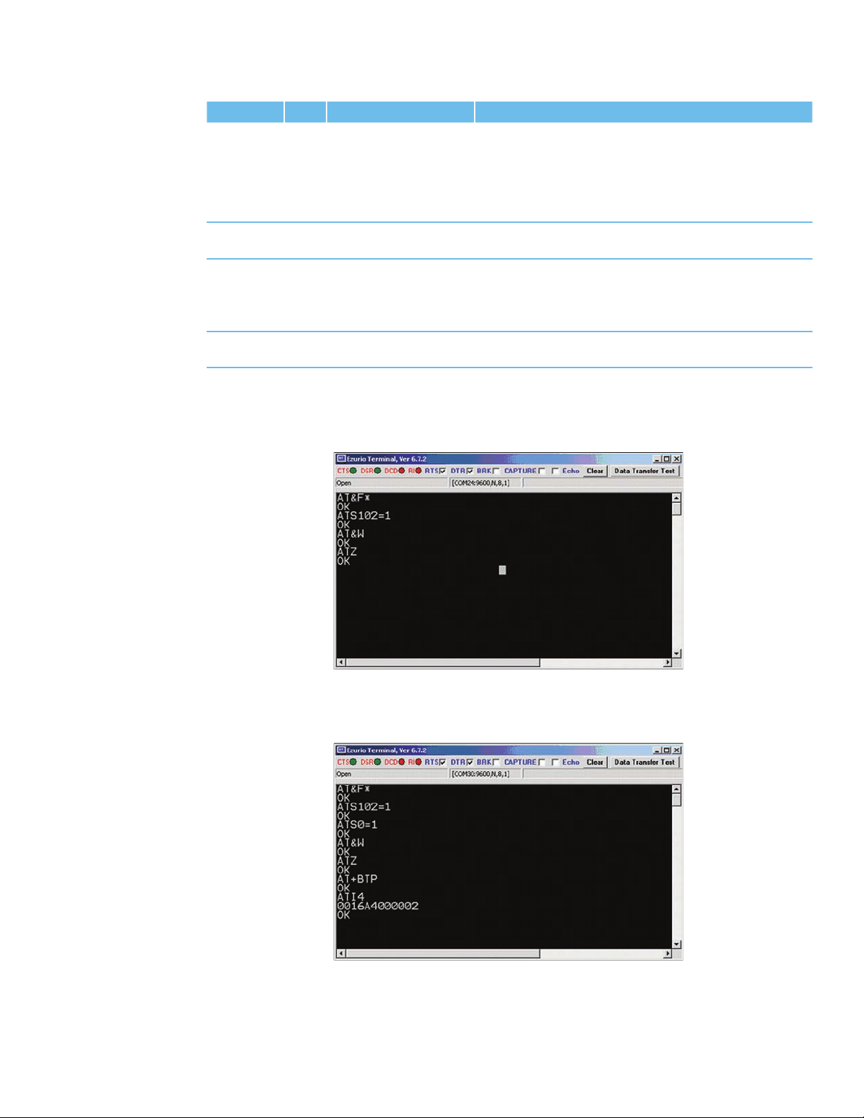
Figure 3.2 through to Figure 3.5 are presenting appropriate screenshots with Ezurio Terminal.
Phase Dev. AT Command Comment
Preparation A AT&F* Restore factory default settings
ATS102=1 Enable Serial Port Prole (SPP)
AT&W Store settings
ATZ Reset
Preparation B AT&F* Restore factory default settings
ATS102=1 Enable Serial Port Prole (SPP)
ATS0=1 Automatic response after one “RING”
AT&W Store settings
ATZ Reset
AT+BTP Make device temporary connectable and discoverable
ATI4 Query Bluetooth device address of local device <BdAddr_DevB>
www.lairdtech.com
29
Laird Technologies
Page 30
BTM510/511
Bluetooth® Multimedia Module
AT COMMAND SET
REFERENCE
Phase Dev. AT Command Comment
Initiate
connection
Connected A,B <data> Any character entered on one end is displayed at the
Enter
command
mode
Disconnect AT+SPH Response “NO CARRIER…” (A and B): disconnection
A AT+SPD<BdAddr_DevB> Initiate SPP connection from device A to device B.
Asynchronous messages:
“PAIR 0…” (pairing successful, A and B)
“RING…” (B only)
“CONNECT…” (connected, A and B)
other end.
A or B^^^ Response “OK” :
Command mode conrmed, now AT commands are
expected at the UART; UART data from host is not sent
across to remote device.
conrmed.
Table 3.9: SPP Example Command Sequence
www.lairdtech.com
30
Figure 3.2: SPP example - Preparation of Device A
Figure 3.3 SPP example – Preparation of Device B
Laird Technologies
Page 31

BTM510/511
Bluetooth® Multimedia Module
AT COMMAND SET
REFERENCE
Figure 3.4: SPP example Device A - initiate connection, receiving data, command mode, disconnect
Figure 3.5: SPP example Device B - incoming connection, receiving data, disconnection
2.2 ATA {Accept Incoming SPP Connection Request}
Accept an incoming connection, which is indicated by the unsolicited string <cr,lf>RING
123456789012<cr,lf> every second. 123456789012 is the Bluetooth address of the
connecting device.
Response: <cr,lf>CONNECT 123456789012,1101,<<cr,lf>
2.3 AT+SPD<bd_addr> {Make Outgoing SPP Connection}
Initiate an SPP connection to device with Bluetooth address <bd_addr> and SPP prole.
The timeout is specied by S register 505.
For backward compatibility, the following command fulls the same purpose: ATD<bd_addr>.
Response: <cr,lf>CONNECT 123456789012,1101,><cr,lf>
Or <cr,lf>NO CARRIER<cr,lf>
Due to a known issue in the Bluetooth RFCOMM stack, it is not possible to make more than
65525 outgoing connections in a single power up session. Therefore if that number is exceeded,
then the connection attempt will fail with the following response:
Response: <cr,lf>CALL LIMIT
Or <cr,lf>NO CARRIER<cr,lf>
In that case, issuing an ATZ to reset the device will reset the count to 0 and more connections
are possible.
www.lairdtech.com
31
Laird Technologies
Page 32

BTM510/511
Bluetooth® Multimedia Module
AT COMMAND SET
REFERENCE
2.4 AT+SPDL {Remake Connection}
Make a SPP connection with the same device as that specied in the most recent AT+SPD
command. An error will be returned if the ‘L’ modier is specied AND a Bluetooth address.
For backward compatibility, the following command fulls the same purpose: ATDL
Response: <cr,lf>CONNECT 123456789012,><cr,lf>
Or <cr,lf>NO CARRIER<cr,lf>
2.5 AT+SPDR {MakeSPPConnectiontoPeerSpeciedinAT+BTR}
Make a SPP connection with the device address specied in the most recent AT+BTR command.
An error will be returned if the ‘R’ modier is specied AND a Bluetooth address.
For backward compatibility, the following command fulls the same purpose: ATDR
Response: <cr,lf>CONNECT 123456789012,><cr,lf>
Or <cr,lf>NO CARRIER<cr,lf>
2.6 AT+SPH {Drop SPP Connection}
Drop an existing SPP connection or reject an incoming connection indicated by unsolicited
RING messages.
For backward compatibility, the following command fulls the same purpose: ATH
Response: <cr,lf>NO CARRIER<cr,lf>
2.7 SPP – Incoming Connections
The Laird Technologies BTM device can be congured using the AT+BTP or AT+BTG command
so that it will scan for incoming connections from other Bluetooth devices. It can also be
congured via S Register 512 to be in this mode by default on power up.
When the lower layers detect an SPP connection request, a RING 123456789012 string is sent
to the host every second. The command ATA is used to accept the connection and ATH to
reject the request.
On connection, if the S0 Register is >=0 then conrmation to the host is in the form:
CONNECT 123456789012,1101,<
When S0 register is -1, neither RING nor CONNECT is sent to the host and the connection is
silently accepted.
If the S 100 register is non-zero, then after the ring indications specied by this register have
been sent to the host, and the host has failed to accept or reject the incoming connection,
then an automatic ‘hangup’ is initiated.
www.lairdtech.com
32
2.8 SPP – Asynchronous Messages
RING
This string is sent to the host when a remote device is initiating a serial port connection.
The fully qualied string is in the form RING 012345678901 where 012345678901 is a
12 digit hexadecimal number which corresponds to the remote device’s Bluetooth address.
This response is sent to the host every two seconds until the host either accepts the connection
using the ATA command or rejects it using the ATH command.
CONNECT 123456789012,1101,<
An SPP connection has with Bluetooth device 123456789012 has been established successfully.
The connection was initiated by the remote device (incoming).
CONNECT 123456789012,1101,>
An SPP connection has with Bluetooth device 123456789012 has been established successfully.
The connection was initiated by the local device (outgoing).
Laird Technologies
Page 33

BTM510/511
Bluetooth® Multimedia Module
AT COMMAND SET
REFERENCE
2.9 SPP – S Registers
S Registers for SPP are summarized in Table 3.10.
Register Default Range Description
S0 0 -1..15 Number of RING indication before automatically
answering an incoming connection. A value of 0
disables autoanswer. If -1, then autoanswer on one
RING and do NOT send RING/CONNECT response
to the host. This emulates a serial cable replacement
situation Setting values >= 0, resets S Register 504 to
0 and <0 forces 504 to 1.
If S0 <> 0 and S100 <> 0 then S0 must be < S100. If
a value is entered which violates this rule, then ERROR
29 is sent in response.
If S504 =1 then this register will return -1, regardless
of the actual value stored in non-volatile memory.
S100 15 0..15 Number of RING indications before an auto
disconnection is initiated. A value of 0 disables
this feature. If S0 <> 0 and S100 <> 0 then S0
must be < S100. If a value is entered which violates
this rule, then ERROR 29 is sent in response.
Table 3.10: S Registers for SPP
3. A2DP(AdvancedAudioDistributionProle)
The “Advanced Audio Distribution Prole” is used for unidirectional transmission of high quality audio
streams between two Bluetooth devices. A2DP must be enabled by setting S 102 to a value of 128.
Also, an A2DP role must be assigned to a BTM module, either source or sink. After this has been done,
the settings need to be stored by AT&W followed by ATZ.
An incoming A2DP connection request is accepted automatically if a valid link key for the paging device
exists. If no link key is available, Secure Simple Pairing (SSP, BT2.1) or legacy pairing (BT2.0 or earlier) is
carried out, depending on the Bluetooth version of the paging device.
After an A2DP connection has been established, the module remains in AT Command mode. S Register
531 is ignored for A2DP connections.
Version 1.2 of A2DP is supported.
The A2DP service record contains an optional eld which indicates the A2DP supported features of
a device. This feature eld can be set by S312 for a sink and by S313 for a source. Please refer to
Table 3.16 for details.
Table 3.17 gives an overview on supported A2DP features on a BTM device.
Table 3.12 lists supported A2DP codec types.
www.lairdtech.com
33
A2DP Feature Support in SRC (Audio Source) Support in SNK (Audio Sink)
Spec. BTM5xx Spec. BTM5xx
1. Audio Streaming M Yes M Yes
M: mandatory
Table 3.11: A2DP Supported Features on BTM5xx
A2DP Codec Type Support in SRC (Audio Source) Support in SNK (Audio Sink)
Spec. BTM5xx Spec. BTM5xx
1. SBC M Yes M Yes
2. MPEG-1,2 Audio O No O No
3. MPEG-2,4 AAC O No O No
4. ATRAC family O No O No
M: mandatory
O: optional
Table 3.12: A2DP Supported Codec Types on BTM5xx
Laird Technologies
Page 34

BTM510/511
Bluetooth® Multimedia Module
AT COMMAND SET
REFERENCE
3.1 A2DP Example 1
This section gives an example of an A2DP connection between a Laird Technologies BTM device as
Audio Sink (wireless speaker/ wireless headphones) and a PC with a built in Bluetooth device and
Toshiba Bluetooth Stack 2.1 as Audio Source.
The PC must support A2DP. If it is a different stack the procedure should be similar and follow
the steps of:
1.) Device discovery
2.) Device Selection
3.) Pairing
4.) Connection establishment (e.g., initiated by PC)
If you have a Bluetooth 2.0 or earlier stack on your PC, legacy pairing with PIN will occur. In that
case use AT+BTK=”<PIN>” to enter the PIN on the BTM device.
The BTM5xx device is assumed to be connected to a terminal program e.g. Ezurio Terminal on
a PC. The sequence of AT commands and the instructions for the PC side are listed in Table 3.13.
Figure 3.6 through to Figure 3.11 show appropriate screenshots.
Phase Dev. AT Command Comment
Preparation BTM5xx AT&F* Restore factory default settings
A2DP prole is enabled per default in S102
Audio Sink role is enabled per default in S300
ATS515=$040400 Set A2DP device class
ATS512=4 Make device connectable and discoverable (permanent setting)
AT&W Store settings
ATZ Reset
Preparation /
Connection
setup
Connected BTM5xx n/a Music can be heard on the speakers/headphones
Adjust
Volume
Disconnect AT+APH Response “NO CARRIER 110D”: disconnection conrmed
PC n/a 1.) Open “Bluetooth Settings” from the taskbar icon - Figure 3.6
2.) Click on “New Connection” - Figure 3.6
3.) Click Next (Discover BT Devices) - Figure 3.7
4.) Select “Laird BTMM…” if not listed: click “Refresh” - Figure 3.8
5.) Click “Yes” on “Allow this Device to connect?” - Figure 3.9
6.) Connection is initiated by PC - Figure 3.10
7.) Open a player (e.g., Windows Media Player) to play some
music
8.) Connect a Headphone/Speaker to the Audio Output of the
BTM device
Troubleshooting:
If nothing can be heard, verify that a Bluetooth Audio Device
has appeared in the Device Manager - Figure 3.1. Also check
that the Bluetooth Audio Device is selected as speaker in your
player application. Sometimes a player needs to be closed and
restarted in order to send its audio output to a new speaker
device (which is the Bluetooth Audio Device here).
AT+GOU Increment volume (audio output gain) by one
AT+GOD Decrement volume (audio output gain) by one
Table 3.13: A2DP Example 1 Command Sequence
www.lairdtech.com
34
Laird Technologies
Page 35

BTM510/511
Bluetooth® Multimedia Module
AT COMMAND SET
REFERENCE
Figure 3.6: A2DP example 1 – PC Bluetooth settings
Figure 3.7: A2DP example 1 – Start discovery of Bluetooth devices
www.lairdtech.com
35
Laird Technologies
Page 36

BTM510/511
Bluetooth® Multimedia Module
AT COMMAND SET
REFERENCE
Figure 3.8: A2DP example 1 – Select Bluetooth device (Click “Refresh” if Laird BTMM is not listed)
Figure 3.9: A2DP example 1 – Conrm pairing (here: Secure Simple Pairing, no PIN required)
Figure 3.10: A2DP example 1: Connection established
www.lairdtech.com
36
Laird Technologies
Page 37

BTM510/511
Bluetooth® Multimedia Module
AT COMMAND SET
REFERENCE
Figure 3.11: A2DP example 1: New Bluetooth Audio Device in the Device Manager
3.2 A2DP Example 2
This section gives an example of an A2DP connection between a Laird Technologies BTM5xx device
(A) as Audio Sink (wireless speaker/ wireless headphones) and another Laird Technologies BTM5xx
device (B) as Audio source.
Both BTM5xx devices are assumed to be connected via UART to a terminal program, e.g., Ezurio
Terminal on a PC. The required instructions along with the sequence of AT commands are listed
in Table 3.14. Figure 3.12 to Figure 3.15 show appropriate screenshots.
Phase Dev. AT Command Comment
Preparation ext.
audio
equipm.
Preparation A AT&F* Restore factory default settings
ATS515=$040400 Set A2DP device class (Sink)
ATS512=4 Make device connectable and discoverable (permanent setting)
AT&W Store settings
ATZ Reset
ATI4 Query Bluetooth device address of Dev. A <BdAddr_DevA>
1.) Connect an audio source (e.g., MP3 player) to the stereo
audio input (line in) of Device B.
2.) Connect a headphone or a speaker to the stereo audio
output (line out) of device A
A2DP prole is enabled per default in S102
Audio Sink role is enabled per default in S300
www.lairdtech.com
37
Laird Technologies
Page 38

BTM510/511
Bluetooth® Multimedia Module
AT COMMAND SET
REFERENCE
Phase Dev. AT Command Comment
Preparation B AT&F* Restore factory default settings
A2DP prole is enabled per default in S102
ATS300=2 Enable Audio Source role
ATS515=$080400 Set A2DP device class (source)
AT&W Store settings
ATZ Reset
Initiate
Connection
Connected Play music from the audio source
Adjust
Volume
Disconnect A/B AT+APH Response “NO CARRIER 110D”: disconnection conrmed
B AT+APD<BdAddr_
DevA>
A AT+GOU Increment volume (audio output gain) by one
AT+GOD Decrement volume (audio output gain) by one
B AT+GIU Increment volume (audio input gain) by one
AT+GID Decrement volume (audio input gain) by one
Table 3.14: A2DP Example 2 Command Sequence and Instructions
Response:
“PAIR 0…” (pairing successful, A and B)
“CONNECT…” (connected, A and B)
Music should be audible on the headphones/speakers. If not:
check audio output of the audio source (e.g., connect headphones directly to audio source for a test)
Note: the audio input gain (A2DP source) is a critical setting
because the optimal setting cannot be veried by objective
means by the module itself.
www.lairdtech.com
38
Figure 3.12: A2DP Example 2 – Preparation of Device A (Sink)
Figure 3.13: A2DP Example 2 – Preparation of Device B (Source)
Laird Technologies
Page 39

BTM510/511
Bluetooth® Multimedia Module
AT COMMAND SET
REFERENCE
Figure 3.14: A2DP Example 2 –Initiate and Release Connection from Device B (Source)
Figure 3.15: A2DP Example 2 – Accepting Connection and Volume Adjustment Device A (Sink)
3.3 Enable A2DP
The advanced audio distribution prole (A2DP) is enabled by issuing ATS102=128. After verifying
that a role has been set (S300 != 0) the S registers must be saved by AT&W. Finally issue ATZ to
make the new settings effective. If the A2DP ag in S102 (0x80) is not set after ATZ although it
was set and saved before ATZ, then S300 was = 0 at boot time, which is invalid for A2DP.
3.4 Select A2DP Role
The A2DP role is selected by S register 300 as follows:
0 – no role selected
1 – A2DP Sink (default)
2 – A2DP Source
The setting must be saved by AT&W and becomes effective on next power cycle (ATZ).
CAUTION: If S 300=0 at boot time (no role selected) and the A2DP ag (0x80) is set in S102,
the A2DP ag will be cleared automatically because A2DP cannot be enabled without a role selected.
www.lairdtech.com
39
Laird Technologies
Page 40

BTM510/511
Bluetooth® Multimedia Module
AT COMMAND SET
REFERENCE
4. Set A2DP Device Class
ATS515=$<device_class
>; AT&W; ATZ
hex
For compliance with the A2DP specication, [2] (and hence for successful interoperability to other
devices) it is required to set up a valid device class code. The default device class code of a BTM device
is 0x001F00 which is invalid for the A2DP prole.
The A2DP specication [2] mandates the following requirements for the device class of an A2DP device:
1. Mandatory to set the ‘Rendering’ bit for the SNK and the ‘Capturing’ bit for the SRC in the Service
Class eld.
2. Recommended to set ‘Audio/Video’ as Major Device class both for the SNK and the SRC.
3. Select the appropriate Minor Device class as dened in the Bluetooth Assigned Numbers [8].
There is a tool available on the internet for creating a particular device class code: refer to [9].
With the assumptions above (Major Device class = Audio/Video), Table 8 in [8] gives the complete list
of codes for the minor device class. If you are not sure about the minor device class, use the row
marked with n/a for the minor device (e.g., 0x040400 for sink or 0x080400 for source).
Table 3.15 gives some examples of device class codes for A2DP devices.
Device Class Code Major Service Major Device Minor Device A2DP Role
0x040400 Rendering Audio/Video n/a Sink
0x040414 Rendering Audio/Video Loudspeaker Sink
0x040418 Rendering Audio/Video Headphones Sink
0x04041C Rendering Audio/Video Portable Audio Sink
0x040420 Rendering Audio/Video Car audio Sink
0x080400 Capturing Audio/Video n/a Source
0x080410 Capturing Audio/Video Microphone Source
0x080428 Capturing Audio/Video HiFi Audio Device Source
Table 3.15: A2DP device class code – examples
The device class is written to the module using ATS515=$<device_class
is the 6 character device class code without leading “0x”. Use subsequent AT&W and ATZ for the new
> where <device_class
hex
>
hex
value to become effective. Please also refer to page 13, number 4.
www.lairdtech.com
40
4.1 Initiate A2DP Connection
AT+APD<bd_addr
Initiate A2DP connection to Bluetooth address <bd_addr
complementary role to the local device. If link keys are missing in one or both devices, pairing
will either occur automatically or pairing is required to be initiated by AT+BTW<bd_addr
This depends on various factors like the combination of local and remote IO capabilities or the
hex
>
>. The remote device must support the
hex
>.
hex
Bluetooth version of the remote device.
Response:
<cr><lf>OK<cr><lf> (immediately)
<cr><lf>PAIR 0 <bd_addr> 00<cr><lf> (rst time only, auto pairing without MITM authent.)
<cr><lf>CONNECT <bd_addr>,110D,><cr><lf>
Or:
<cr><lf>OK<cr><lf> (immediately)
<cr><lf>NO CARRIER 110D<cr><lf> (not successful)
Laird Technologies
Page 41

BTM510/511
Bluetooth® Multimedia Module
AT COMMAND SET
REFERENCE
4.2 Output Gain Settings – A2DP Sink
AT+GOU / AT+GOD
AT+GOU – Increment audio output gain (volume).
AT+GOD – Decrement audio output gain (volume).
Response:
<cr><lf>OK<cr><lf>
<cr><lf>ERROR 57<cr><lf> – Maximum gain level reached
<cr><lf>ERROR 58<cr><lf> – Minimum gain level reached
The output gain level can be set directly using S register 589. Alternatively, S register 689 can be
used to set the required overall output gain in dBr multiplied by 10. Please refer to section 1, page 74.
4.3 Input Gain Settings – A2DP Source
AT+GIU / AT+GID
AT+GIU – Increment audio input gain.
AT+GID – Decrement audio input gain.
Response:
<cr><lf>OK<cr><lf>
<cr><lf>ERROR 57<cr><lf> – Maximum gain level reached
<cr><lf>ERROR 58<cr><lf> – Minimum gain level reached
The input gain level can be set directly using S register 590. Alternatively, S register 690 can be
used to set the required overall input gain in dBr multiplied by 10. Please refer to section 1, page 74.
4.4 Release A2DP Connection
AT+APH / ATH110D
Release an A2DP connection by AT+APH. Alternatively, ATH110D can be used. (110D presents
the UUID for the A2DP prole). Please refer to section4, page 83.
4.5 Supported Features – A2DP Sink
S312
Use S Register 312 to set the A2DP sink supported features that will be advertised in the A2DP
service record. Refer to Table 3.16. The S register needs to be saved (AT&W) and the module
needs to be power cycled (ATZ) for a new value to become effective.
4.6 Supported Features – A2DP Source
S313
Use S Register 313 to set the A2DP source supported features that will be advertised in the A2DP
service record. Refer to Table 3.16. The S register needs to be saved (AT&W) and the module
needs to be power cycled (ATZ) for a new value to become effective.
Task AT-Command / SRegister Comment
Enable A2DP prole S102 128 = A2DP, Error 46 if A2DP role has not been
set (see S300)
Needs subsequent AT&W and ATZ to
become effective
Set A2DP role S300 [0..2] 0 = feature not set
1 = A2DP Sink (default)
2 = A2DP Source
Needs subsequent AT&W and ATZ to
become effective
www.lairdtech.com
41
Laird Technologies
Page 42

BTM510/511
Bluetooth® Multimedia Module
AT COMMAND SET
REFERENCE
Task AT-Command / SRegister Comment
Initiate outgoing A2DP connection
Close only A2DP connection “AT+APH” or
Close all connections ATH* Response:
Set gain level S589 [0..22], default = 15Set codec output gain level (applies to sink)
Set overall gain (dBr * 10) S689 [-450..215] Set codec output gain in dBr * 10
Increment Gain AT+GOU Increment codec output gain by 1 step in gain
Decrement Gain AT+GOD Decrement codec output gain by 1 step in gain
Set A2DP Sink supported
features bit mask
Set A2DP Source supported
features bit mask
AT+APD<bd_addr> Response if accepted:
“CONNECT 0123456789012,110D,>”
Response if rejected:
“NO CARRIER 110D”
Response:
“ATH110D”
S590 [0..22], default = 15Set codec input gain level (applies to source)
S690 [-450..215] Set codec input gain in dBr * 10
AT+GIU Increment codec input gain by 1 step in gain table
AT+GID Decrement codec input gain by 1 step in gain table
S312 [1..15] Bitmask - sink supported features:
S313 [1..15] Bitmask - source supported features:
Table 3.16: A2DP – S Registers and AT-Commands
“NO CARRIER 110D” if connection has existed and
S329=0
“NO CARRIER” if connection has not existed and
S329=0
“NO CARRIER <proleUUID>” for each prole that
was previously connected (see section 4, page 83)
(applies to sink), default = 0
(applies to source), default = 0
table (refer to section 1, page 74)
(refer to section 1, page 74)
table (refer to section 1, page 74)
(refer to section 1, page 74)
Bit 0 = Headphone (default)
Bit 1 = Speaker
Bit 2 = Recorder
Bit 3 = Amplier
Subsequent AT&W plus ATZ required for a new
value to become effective
Bit 0 = Player (default)
Bit 1 = Microphone
Bit 2 = Tuner
Bit 3 = Mixer
Subsequent AT&W plus ATZ required for a new
value to become effective
www.lairdtech.com
42
Laird Technologies
Page 43

BTM510/511
Bluetooth® Multimedia Module
AT COMMAND SET
REFERENCE
5 AVRCP(AudioVideoRemoteControlProle)
The “Audio/Video Remote Control Prole” is used to remotely control audio or video streaming devices.
A device must be dened as either control (CT) or target (TG). Furthermore, one of four categories
(Player/Recorder, Monitor/Amplier, Tuner, Menu) must be assigned to a device.
Version 1.0 of AVRCVP is supported.
The AVRCP specication [3] adopts the AV/C Digital Interface Command Set (AV/C command set,
dened by the 1394 Trade Association) device model and control message format. In this device model
a remote control target consists of one or more subunits. At least the subunit ”PANEL” must exist.
Remote control commands are passed to a subunit with the “PASS THROUGH” command. A BTM
device, congured as target will support one PANEL-subunit.
Table 3.17 gives an overview on supported AVRCP features on a BTM device.
AVRCP Feature Support in CT (Control) Support in TG (Target)
Spec. BTM5xx Spec. BTM5xx
1. Connection establishment for control M Yes O Yes
2. Release connection for control M Yes M Yes
3. Sending UNIT INFO command O Yes X No
4. Receiving UNIT INFO command X No M Yes
5. Sending SUBUNIT INFO command O (1) X No
6. Receiving SUBUNIT INFO command X No M Yes
7. Sending VENDOR DEPENDENT command O No X No
8. Receiving VENDOR DEPENDENT command X No O No
9. Sending PASS THROUGH command M Yes X No
10. Receiving PASS THROUGH command X No M Yes
M: mandatory
O: optional
X: excluded
(1) incomplete
Table 3.17: AVRCP Supported Features on BTM5xx
5.1 AVRCP Example 1
This section gives an example of an AVRCP connection between a Laird Technologies BTM5xx
device as AVRCP Controller and a PC with a built in Bluetooth device and Toshiba Bluetooth Stack
2.1 as AVRCP Target.
For any other Bluetooth Stack with AVRCP (target role) support, the setup should follow the steps of:
1. Identifying Bluetooth Device Address of PC
2. Enabling AV Remote Control Service
3. Selecting player and/or setup display of incoming remote control commands
The BTM5xx device is assumed to be connected to a terminal program, e.g., Ezurio Terminal on a
PC. The sequence of AT commands and the instructions for the PC side are listed in Table 3.18.
Figure 3.16 to Figure 3.21 show appropriate screenshots.
This example can be combined with the A2DP Example 1 (Section3.1, page 34). Then the AVRCP
connection should be initiated after A2DP is connected.
www.lairdtech.com
43
Laird Technologies
Page 44

BTM510/511
Bluetooth® Multimedia Module
AT COMMAND SET
REFERENCE
Phase Dev. AT Command Comment
Preparation BTM5xx AT&F* Restore factory default settings
AVRCP prole is enabled per default in S102
AVRCP Control role is enabled per default in S301
ATZ Reset
Preparation PC n/a 1.) Select “Options…” from the Bluetooth icon in the
taskbar (Figure 3.16)
2.) Identify the PC’s Bluetooth Address <BdAddr_PC> in
the “General” tab of Bluetooth Options (Figure 3.16)
3.) Make sure that “AV Remote Control Service is enabled” (Figure 3.16)
4.) Go to “Other” tab of Bluetooth Options and Click
Button “AV Player…” (Figure 3.17)
5.) Select “TopRight” at the “Display Position” dropdown
menu (Figure 3.17)
6.) Close each window by clicking “OK”
Initiate
Connection
Connected,
send remote
control
commands
Disconnect BTM5xx AT+AVH Response: (Figure 3.20)
BTM5xx AT+AVD<BdAddr_PC> Response: (Figure 3.19)
“CONNECT <BdAddr_PC>,110E,>” (AVRCP connected)
BTM5xx AT+AVC44 Send “Play” (Figure 3.20, Figure 3.21)
Response:
“OK” - command accepted
“AVPTC 0,44,0” -conrmation received from PC
“AVPTC 0,44,1” -conrmation received from PC
Reception of command should be displayed in top-right
corner of PC screen (Figure 3.21), Player should start
playing.
AT+AVC46 Send “Pause” (Figure 3.20, Figure 3.21)
Response:
“OK” - command accepted
“AVPTC 0,46,0” -conrmation received from PC
“AVPTC 0,46,1” -conrmation received from PC
Reception of command should be displayed in top-right
corner of PC screen (Figure 3.21), Player should pause.
AT+AVC45 Send “Stop” (Figure 3.21)
Response:
“OK” - command accepted
“AVPTC 0,45,0” -conrmation received from PC
“AVPTC 0,45,1” -conrmation received from PC
“NO CARRIER 110E” (disconnection conrmed)
Table 3.18: AVRCP Example 1 Command Sequence
www.lairdtech.com
44
Laird Technologies
Page 45

BTM510/511
Bluetooth® Multimedia Module
AT COMMAND SET
REFERENCE
Figure 3.16: AVRCP Example 1 – Bluetooth Address of PC and AV Remote Control Service
www.lairdtech.com
45
Figure 3.17: AVRCP Example 1 – Player Selection and Receiving Commands Display Setup
Laird Technologies
Page 46

BTM510/511
Bluetooth® Multimedia Module
AT COMMAND SET
REFERENCE
Figure 3.18: AVRCP Example 1 – Secure simple pairing dialogue
Figure 3.19: AVRCP Example 1 – BTM5xx Preparation and Connection Setup
Figure 3.20: AVRCP Example 1 – BTM5xx Sending Commands and Connection Release
www.lairdtech.com
46
Figure 3.21: AVRCP Example 1 – Incoming AVRCP commands (top-right corner of screen)
Laird Technologies
Page 47

BTM510/511
Bluetooth® Multimedia Module
AT COMMAND SET
REFERENCE
5.2 AVRCP - Control (CT) and Target (TG)
This section describes AT Commands an S registers which are common to BTM5xx AVRCP
Controller role and AVRCP Target role.
5.2.1 Initiate AVRCP Connection
AT+AVD<bd_addr
Initiate AVRCP control connection to Bluetooth address <bd_addr
be congured as AVRCP Control by S register 301 = 1. Furthermore, a category must be
>
hex
>. The module must
hex
selected in S register 302.
Response: <cr,lf>CONNECT 123456789012,110E,><cr,lf>
Or: <cr,lf>NO CARRIER 110E<cr,lf>
Or: <cr,lf>ERROR 47<cr,lf>
Or: <cr,lf>ERROR 48<cr,lf>
After an AVRCP connection has been established, the module remains in AT command
mode. S Register 531 is ignored for AVRCP connections.
5.2.2 Release AVRCP Control Connection
AT+AVH
Release AVRCP control connection.
Response <cr,lf >NO CARRIER 110E<cr,lf>
5.3 AVRCP - Control (CT)
This section describes AT Commands an S registers when BTM5xx is congured as an AVRCP
Controller (S301=1).
5.3.1 Send UNIT INFO Request
AT+AVU
Send a Unit Info request to a connected AVRCP target.
Response immediately: <cr,lf>OK<cr,lf>
On command completion:
<cr,lf>AVUR <n>,<unit_id
<n> = status
: 0 – success
dec
>,<unit_type
hex
>,<company_id
hex
><cr,lf>
hex
1 – fail
4 – timeout
For unit_type see Table 3.21: AV/C Unit/Subunit Types.
5.3.2 Send SUBUNIT INFO Request (Incomplete*)
AT+AVS<page
dec
>
Send a Subunit Info request to a connected AVRCP target.
Response: <cr,lf>OK<cr,lf> (immediately)
And: <cr,lf>AVSR <n>,<page
<n> = status
: 0 – success
dec
>,<pagedata
dec
> <cr,lf> (after command completion)
hex
1 – fail
4 – timeout
<page
<pagedata
> : requested page [0..31]
dec
>: 1st word of requested page
hex
*) incomplete because only the rst word of the requested page is being displayed in the
AVSR asynchronous message
www.lairdtech.com
47
Laird Technologies
Page 48

BTM510/511
Bluetooth® Multimedia Module
AT COMMAND SET
REFERENCE
5.3.3 Send Remote Control Command
AT+AVC<operation_id
Send a remote control command to a connected AVRCP target. Internally, a PASS THROUGH
command is created and sent to the PANEL subunit of the AVRCP target.
<operation_id
specied in Table 3.20. Some Operation IDs can be replaced by mnemonics, see Table 3.20.
<button_state> represents “Button pushed” (=0) or “Button released” (=1) If <button_state>
is not specied, two PASS THROUGH commands, each with button_state=0 and
button_state=1, will be created and being sent consecutively.
The “OK” response is sent immediately on receipt of AT+AVC command. On command
completion, an unsolicited message will be sent to the host in the form “AVPTC <n>,
<bd_addr>, <button_state>”. AVPTC means “AVrcp Pass Through Conrmation”.
Parameter n indicates the command’s status:
‘n’=0: successful, command conrmation received from target
‘n’=1: timeout, target has not sent conrmation within the specied maximum time
‘n’=2: all other unsuccessful outcomes
Parameters:
<operation_id
<button_state> (optional) : ‘0’ - Button pushed
‘1’ - Button released
Response: <cr,lf>OK<cr,lf> (immediately)
And: <cr,lf>AVPTC <n>,<operation_id
(after command completion)
If status n indicates an unsuccessful outcome,<operation_id
5.4 AVRCP – Target (TG)
This section describes AT Commands an S registers when BTM5xx is congured as an AVRCP
Target (S301=2). In this mode, BTM5xx supports one subunit PANEL (see [3]).
> is the value for the actual remote control command. Valid values are
hex
> (mandatory): see Table 3.20
hex
>,<button_state>
hex
>,<button_state><cr,lf>
hex
> and <button_state> are omitted.
hex
5.4.1 Incoming AVRCP Connection Request
An incoming AVRCP connection request is accepted automatically if a valid link key for the
paging device exists. If no link key is available, Secure Simple Pairing (SSP, BT2.1) or legacy
pairing (BT2.0 or earlier) is carried out, depending on the Bluetooth Version of the paging device.
After an AVRCP connection has been established, the module remains in AT command
mode. S Register 531 is ignored for AVRCP connections.
5.4.2 UNIT INFO Response
It is mandatory to respond to a UNIT INFO command if congured as AVRCP target.
Required response parameters are IEEE Company ID and a Unit Type.
The IEEE Company ID is a 24 bit integer which can be set via S Register 303.
The response is sent automatically with the company ID as per S303 and a xed unit
type of 0x09 (“Panel”).
5.4.3 SUBUNIT INFO Response
It is mandatory to respond to a SUBUNIT INFO command if congured as AVRCP target.
Required response parameters are Subunit type and MaxSubUnitId.
The response is sent automatically with a xed value of 0x09 (“Panel”) for parameter
Subunit type and a xed value of 0x00 for parameter MaxSubUnitId (only one subunit exists,
which is panel).
www.lairdtech.com
48
Laird Technologies
Page 49

BTM510/511
Bluetooth® Multimedia Module
AT COMMAND SET
REFERENCE
5.4.4 PASS THROUGH Indication
An incoming PASS THROUGH command will be indicated by an unsolicited message.
AVPTI <subunit_id
For subunit_id
>,<operation_id
hex
see Table 3.21. For operation_id
hex
>,<button_state>
hex
see Table 3.20.
hex
<button_state>: ‘0’ is Button pushed
‘1’ is Button released
5.4.5 PASS THROUGH Response
AT+AVR<avrc_response_type
hex
>
If S register 310 == 0, a Pass Through (PT) response is required from the host. The response
is sent using the command:
AT+AVR<avrc_response_type
>
dec
Parameter:
<avrc_response_type
>: see Table 3.22, write-value.
dec
If S register 310 == 1, a Pass Through response is sent automatically with an
<avrc_response_type> dened by S register 311. In this case, the host is not required to respond.
Task AT-Command / S Register Comment
Enable AVRCP prole S102 256 = AVRCP, Error 47 if AVRCP role has not
been set (see S301);
Error 48 if S301== 2 and Category has not
been set (see S302)
Needs subsequent AT&W and ATZ to be-
come effective
Set AVRCP role S301 [0..2] 0 = disabled
1 = Control “CT” (default)
2 = Target “TG”
Needs subsequent AT&W and ATZ to be-
come effective
Set AVRCP category S302 [0..4] 0 = Feature disabled (default)
1 = Player/Recorder
2 = Monitor/Amplier
3 = Tuner
4 = Menu
Needs subsequent AT&W and ATZ to be-
come effective
Initiate outgoing AVRCP control connection
AT+AVD<bd_addr> Response if accepted:
“CONNECT 0123456789012,110E,>”
Response if rejected:
“NO CARRIER 110E”
Close only AVRCP connection “AT+AVH“ or “ATH110E” Response:
“NO CARRIER 110E” if connection has
existed and S329=0
“NO CARRIER” if connection has not existed
and S329=0
Close all connections ATH* Response:
“NO CARRIER <proleUUID>” for each
prole that was previously connected (see
section 4, page 83)
Send remote control command
(Control)
AT+AVC<operation_
>,<state>
id
hex
<operation_id
<state> (optional): ‘0’ Button pushed
‘1’ Button released
>: see Table 3.20
hex
Response on command completion:
“AVPTC <n>,<operation_id
>,<state>”
hex
www.lairdtech.com
49
Laird Technologies
Page 50

BTM510/511
Bluetooth® Multimedia Module
AT COMMAND SET
REFERENCE
Task AT-Command / S Register Comment
Send a Unit Info request
(Control)
Send a Subunit Info request
(Control)
AT+AVU Response on command completion: “AVUR
<n>,<unit_id
id
>”
hex
Successful if <n> = 0
>,<unit_type
hex
>,<company_
hex
AT+AVS (incomplete*) Response on command completion:
“AVSR <n>,<page
<cr,lf>”
>,<pagedata
dec
>
hex
Successful if <n> = 0
*) only rst word of the pagedata is being
displayed in the AVSR response message
Set Company Id (Target) S303 [0..0xFFFFFF] IEEE Company ID, 24bit hexadecimal,
Required for UNIT INFO Response in AVRCP
target mode, default value is 0.
Set Unit Type (Target) S304 [0..0xFF] currently always 0x09, read only, reserved for
future usage
Enable Unit Info Response
(Target)
S305 [0..1] 0 – reject incoming Unit Info Requests
1 – accept incoming Unit Info Requests and
send response automatically (default) with
Company ID as per S303 and unit type =
0x09 (“Panel”, xed)
Enable Subunit Info Response
(Target)
S306 [0..1] 0 – reject incoming Subunit Info Requests
1 – accept incoming Subunit Info Requests
and send response automatically (default)
with Subunit type = 0x09 (“Panel”, xed)
and MaxSubUnitId = 0x00 (xed)
Congure PASS THROUGH
(PT) Response (Target)
S310 [0..1] 1 = Enable automatic PT-response, response
type is read from S311, (default)
0 = Host is required to respond to PT-Indica-
tion, see ‘AT+PTR’
Set automatic PT response type
(Target)
S311 [0.. 7] This value is queried for automatic PT-Re-
sponse, see Table 3.22
Default value is “accepted” 1w/ 9r
Respond to incoming Pass
Through command (Target)
AT+AVR<avrc_response_type
> <avrc_response_type
hex
If S 310 == 1, response from host is not
>: see Table 3.22
hex
required.
Table 3.19: AVRCP – S Registers and AT Commands
www.lairdtech.com
50
Laird Technologies
Page 51

BTM510/511
Bluetooth® Multimedia Module
AT COMMAND SET
REFERENCE
www.lairdtech.com
51
Command Operation ID
Select 0x00
Up 0x01
Down 0x02
Left 0x03
Right 0x04
Right up 0x05
Right down 0x06
Left up 0x07
Left down 0x08
Root menu 0x09
Setup menu 0x0A
Contents menu 0x0B
Favourite menu 0x0C
Exit 0x0D
0 0x20
1 0x21
2 0x22
3 0x23
4 0x24
5 0x25
6 0x26
7 0x27
8 0x28
9 0x29
Dot 0x2A
Enter 0x2B
Clear 0x2C
Channel up 0x30
Channel down 0x31
Sound select 0x32
Input select 0x33
Display information 0x34
Help 0x35
Page up 0x36
Page down 0x37
Power 0x40
Volume up 0x41
Volume down 0x42
Mute 0x43
Play 0x44
Stop 0x45
Pause 0x46
Record 0x47
Rewind 0x48
Fast forward 0x49
Eject 0x4A
Forward 0x4B
Backward 0x4C
Angle 0x50
Sub picture 0x51
F1 0x71
F2 0x72
F3 0x73
F4 0x74
F5 0x75
Vendor unique 0x7e
Table 3.20: AVRCP – Operation IDs for Remote Control Commands
Laird Technologies
Page 52

BTM510/511
Bluetooth® Multimedia Module
AT COMMAND SET
REFERENCE
Unit / Subunit Type Value
Monitor 0x00
Audio 0x01
Printer 0x02
Disc 0x03
Tape recorder player 0x04
Tuner 0x05
CA 0x06
Camera 0x07
Reserved 0x08
Panel 0x09
Bulletin board 0x0A
Camera storage 0x0B
Vendor unique 0x1C
Reserved for all 0x1D
Extended 0x1E
Unit 0x1F
Table 3.21: AV/C Unit/Subunit Types
AVRC Response Type Read-Value (S311,
sent in response)
Not implemented 8 0
Accepted 9 1
Rejected 10 2
In transition 11 3
Stable 12 4
Changed 13 5
Interim 15 6
Bad prole 16 7
Table 3.22: AVRC Response Types
Write-Value (S311) or
AT+AVR<parameter>
www.lairdtech.com
52
Message Comment
CONNECT 123456789012,110E,> Outgoing AVRCP connection established
‘123456789012’ – bd_addr of peer device
‘110E’ – UUID indicating AVRCP
CONNECT 123456789012,110E,< Incoming AVRCP connection established
‘123456789012’ – bd_addr of peer device
‘110E’ – UUID indicating AVRCP
NO CARRIER 110E AVRCP connection rejected or closed
NO CARRIER All Connections closed
AVUR <n>,<unit_id>,<unit_type
> <company_id
hex
> Response to AT+AVU (UNIT INFO Request), indicates
hex
completion of command
<n> = status
1 – fail
4 – timeout
<unit_id
<unit_type>: see Table 3.21
<company_id>: IEEE Company ID
: 0 – success
dec
>: Unit ID
hex
Laird Technologies
Page 53

BTM510/511
Bluetooth® Multimedia Module
AT COMMAND SET
REFERENCE
Message Comment
AVSR <n>,<page
>,<pagedata
dec
> Response to AT+AVS (SUBUNIT INFO Request), Indi-
hex
cates completion of command
<n> = status
1 – fail
: 0 – success
dec
4 – timeout
AVPTI <subunit_id
>,<operation_id
hex
<page
<pagedata
>,<state> Indication of incoming Pass Through command
hex
<subunit_id
<operation_id
<state>: ‘0’ – Button pushed
> : requested page [0..31]
dec
> : 1st word of requested page
hex
>: subunit id
hex
>: see Table 3.20
hex
‘1’ – Button released
AVPTC <n>,<operation_id
>,<state> Conrmation of AT+AVC (Control Command
hex
Request)
<n>: ‘0’ – successful
‘1’ – timeout
‘2’ – not successful, other than timeout
Table 3.23: AVRCP Unsolicited Messages
5.5 AVRCP GPIO Mapping
GPIOs can be mapped to AVRCP Commands (operations) with GPIO Conguration Registers S 651
to 663. If Function mapping is enabled (FME=1), and if a valid av_operation_id (see Table 3.20) is
assigned to a GPIO and if the module is congured as AVRCP Control (S 301), a rising edge
causes the appropriate command request to be sent to the connected AVRCP target as if AT+AVC
was issued with <state>=0 (Button pushed). A trailing edge on this GPIO will cause the same
command to be sent with <state>=1 (Button released).
The logical level of a GPIO can be inverted by setting the appropriate ag “INV” in the appropriate
GPIO conguration register.
If congured as AVRCP Target, the direction ag (DIR) in the GPIO Conguration Register must be
set to 1 in order to indicate received commands at a digital output. A write operation to a GPIO
will not have any effect if that GPIO is mapped to AVRCP.
The level inversion Flag INV of the GPIO Conguration Register also applies in target mode.
Restrictions can apply if certain GPIOS will be reserved for other functions in future, e.g.
coexistence supporting functionality.
Please refer to section Error! Reference source not found.
www.lairdtech.com
53
6. HSP(HeadsetProle)
The “Headset Prole” provides full-duplex audio capability combined with minimal device control
commands. Audio bandwidth is limited and deemed to be sufcient for, e.g., voice links. Table 3.24
lists the feature requirements of the HSP specication [4] and the level of support by BTM5xx.
Version 1.2 of the Headset Prole specication is supported.
In most cases it will be preferred to use the more advanced Hands-Free Prole (HFP).
HSP denes the role of the headset (HS) and the role of the audio gateway (AG) which are both
supported on BTM5xx. They are enabled by setting the appropriate ag in S-Register 102 (plus
subsequent “AT&W” and “atz“).
An HSP connection can be in one of two states: ACL connected or audio connected. The ACL is initiated
by either HS or AG. The audio connection (a SCO link) shall always be initiated and released by the AG.
A host processor is required, using AT commands to control the BTM5xx module (hosted operation mode).
An AT command beginning with AT+HS... indicates afliation to the Headset role of HSP.
An AT command beginning with AT+HSG…indicates afliation to the Audio Gateway role of HSP.
Laird Technologies
Page 54

BTM510/511
Bluetooth® Multimedia Module
AT COMMAND SET
REFERENCE
HSP Feature Support in HS Support in AG
Specication BTM5xx Specication BTM5xx
1. Incoming audio connection M Yes M Yes
2. Outgoing audio connection M Yes O Yes
3. Audio connection transfer M Yes M Yes
4. Remote audio volume control O (1) O (1)
M: mandatory
O: optional
(1) Supported planned for future rmware release
Table 3.24: Headset Prole supported features on BTM5xx
6.1 Headset role (HS)
Headset role is activated by setting ag 0x02 in S102 plus “AT&W” plus “ATZ“.
Figure 3.22 shows a block diagram of a headset and how a BTM5xx module would be integrated
in hosted operation mode.
Host
1 Button
Controller
AT command
interface
Speaker
Audio
BTM5xx [HS]
Microphone
Figure 3.22 Headset block diagram
6.1.1 Initiate ACL connection from HS
AT+HSD<bd_addr
Initiate ACL connection from local headset instance to remote device with <bd_addr
The remote device must support the audio gateway role (AG) of the headset prole (HSP).
Response: <cr,lf>CONNECT 123456789012,1112,><cr,lf>
Or: <cr,lf>NO CARRIER<cr,lf>
Or: <cr,lf>ERROR 59<cr,lf>
Or: <cr,lf>ERROR 63<cr,lf>
After an ACL connection has been established, the module remains in AT command mode.
S Register 531 is ignored for HSP connections. An audio connection should be established
within short time. The command is “AT+HSB”.
6.1.2 Send “AT+CKPD=200”
AT+HSB
Send “AT+CKPD=200” to connected audio gateway. This indicates a user initiated action
to the gateway, e.g., a button press. Depending on the current audio connection state,
the audio gateway will establish or release the audio connection subsequently. Please refer
to Table 3.25.
hex
>
>.
hex
www.lairdtech.com
54
Laird Technologies
Page 55

BTM510/511
Bluetooth® Multimedia Module
AT COMMAND SET
REFERENCE
Connection status Outcome of AT+HSB (“AT+CKPD=200”)
ACL connected (ATI63=1) Audio link will be initiated by AG
Referred to as “Audio Connection Transfer from AG to HS” in HSPv1.2
Audio connected (ATI63=2) Audio link and ACL should be released by the AG, actual outcome depends
on AG
Table 3.25: Outcome of “AT+HSB”
6.1.3 Release Connection from Headset
AT+HSH
Release connection from local Headset instance. Audio connection will be released if
existing, ACL will be released anyway.
A connection release, initiated by the Headset, is not dened in the Headset Prole
specication [4]. A prole compliant disconnection is initiated from Headset by sending
“AT+CKPD=200” (use “AT+HSB”) to the audio gateway.
This command was introduced for the sake of completeness and should be used for testing
purposes only.
Response:
On audio disconnection (optional): <cr,lf>HS”AU0”<cr,lf>
On ACL disconnection: <cr,lf>NO CARRIER 1108<cr,lf>
6.1.4 Headset status
ATI63
Returns the status of the Headset (HSP) instance:
0 = not connected
1 = ACL connected
2 = Audio connected
6.1.5 Headset asynchronous messages
CONNECT <bd_addr
An ACL connection to headset has been established.
<bd_addr
<uuid
: “1112” if it was an outgoing connection.
<dir> : “<”/”>”/”I”/”O”’ optionally indicates the direction (incoming/outgoing),
please refer to S331 and section 6, page 85.
HS”RING”
HS has received a “RING” indication from the connected audio gateway. HS is expected
to respond with “AT+CKPD=200” (see “AT+HSB”).
HS”AU1”
Audio connection (SCO) has been established (= “audio on”).
HS”AU0”
Audio connection (SCO) has been released (= “audio off”).
NO CARRIER 1108
ACL connection to local HS-instance has been released. Please note section 6, page 85.
> : Bluetooth address of headset device
hex
> : “1108” if it was an incoming connection
hex
>,<uuid
hex
>[,<dir>]
hex
www.lairdtech.com
55
Laird Technologies
Page 56

BTM510/511
Bluetooth® Multimedia Module
AT COMMAND SET
REFERENCE
6.1.6 Headset summary
Task AT-Command / S Register Comment
Enable HSP-HS role S102 0x02 = HS role of HSP (bitmask), needs
subsequent “AT&W” and “atz” to
activate
Initiate ACL from headset AT+HSD<bd_addr
Send “Button pressed” (HS) AT+HSB Sends “AT+CPKD=200” to the con-
Disconnect from HS AT+HSH / ATH1108 / ATH* For test purposes only, because discon-
Enable “ATH” for HS S332 Enable HS disconnection “ATH1108”
Inquire HS status ATI63 0 = not connected
Table 3.26: Headset role (HSP) – Summary of S Registers and AT Commands
> Responses:
hex
successful: “CONNECT
123456789012,1112,>”
failed: “NO CARRIER”
prole disabled: “ERROR 59”
incorrect state: “ERROR 63”
nected gateway
nection initiated by HS other than send-
ing “AT+CKPD=200” to gateway is not
dened in HSP specication.
and “ATH*”
0 = disabled (default)
1 = enable
Should only be enabled for test purposes, because disconnection initiated by
HS other than sending “AT+CKPD=200”
to gateway is not dened in HSP specication.
1 = ACL connected
2 = Audio connected
6.2 Audio gateway role (AG-HSP / HSG)
Audio gateway role (for HSP) is activated by setting ag 0x08 in S102 plus “AT&W” plus “atz“.
Figure 3.23 outlines a block diagram of an audio gateway with a BTM5xx in hosted operation mode.
local speaker,
local microphone
BTM5xx
Audio Network
Audio routing
Mobile
[HSG] or
control
Termination
[HFG]
Host
AT Command
Interface
(set of buttons / keypad / display)
Controller
Telephone control
www.lairdtech.com
56
Figure 3.23 Audio Gateway block diagram
Laird Technologies
Page 57

BTM510/511
Bluetooth® Multimedia Module
AT COMMAND SET
REFERENCE
6.2.1 Initiate ACL Connection from AG (HSP)
AT+HSGD<bd_addr
Initiate ACL connection from local headset-gateway instance to remote device with <bd_addr
The remote device must support the headset role (HS) of the headset prole (HSP).
Response: <cr,lf>CONNECT 123456789012,1108,><cr,lf>
Or: <cr,lf>NO CARRIER<cr,lf>
Or: <cr,lf>ERROR 59<cr,lf>
Or: <cr,lf>ERROR 63<cr,lf>
After an ACL connection has been established, the module remains in AT command mode.
S Register 531 is ignored for HSP connections.
If S-Register 345=1, the audio gateway will alert the headset immediately by sending
“RING” or by performing the in-band ringing procedure (depending on S Register 346)
and wait for the response “AT+CKPD=200”.
If S-Register 345=0, an incoming call must be signalized to the HS manually by issuing
“AT+HSGC”. This will either send the “RING” message to the HS or perform the in-band
ringing procedure and wait for “AT+CKPD=200” to be received from the HS.
In the case the headset does not respond, it is the host’s responsibility to terminate the
connection by “AT+HSGH”.
6.2.2 Alert HS by Sending “RING” Message or In-Band Ringing
AT+HSGC
When in “ACL connected” state, the command “AT+HSGC” alerts the HS either by sending
“RING” (if S346=0) or by in-band ringing (if S346=1). In the latter the AG is assumed to
create an in-band ringtone which is audible on the HS through the SCO connection. The
in-band ringtone is not created by BTM5xx itself. It is required to be created by the external
circuit and to be connected to the BTM5xx analogue audio input.
In-band ringing is indicated by “ATI64” returning 6. Alerting using the “RING” message is
indicated by “ATI64” returning 5.
In both cases the response “AT+CKDP=200” (“Button pressed”) is expected from the HS.
hex
>
>.
hex
www.lairdtech.com
57
6.2.3 Cancel an Ongoing Alert Process
AT+HSGCH
When the HSG is alerting the HS (ATI64 = 5 / 6 ) this state can be cancelled by “AT+HSGCH”.
If in-band ringing was active (ATI64 = 6) , the audio connection will be released.
6.2.4 Release Audio from HSG Side/Transfer Audio from HS to HSG
AT+HSGR
When in “audio connected” state, the AG can transfer the audio connection from the
headset to itself with “AT+HSGR”. This results in the release of the audio connection
whereas the ACL connection is retained. In “ACL connected” state, the headset (HS) is
able to transfer the audio connection back to the HS by sending “AT+CKPD=200”.
6.2.5 Initiate Audio from HSG Side/Transfer Audio from HSG to HS
AT+HSGA
When in “ACL connected” state, the AG can transfer the audio connection from itself to
the headset by “AT+HSGA”. This results in the establishment of a SCO based audio connection.
6.2.6 Connection Release from AG
AT+HSGH
Release existing connection to a HS. If the HS is alerted, alerting will be cancelled. If an
audio connection exists it will be released rst. ACL will be released in either case.
Response:
On audio disconnection (optional): <cr,lf>HSG”AU0”<cr,lf>
On SLC disconnection: <cr,lf>NO CARRIER 1112<cr,lf>
Laird Technologies
Page 58

BTM510/511
Bluetooth® Multimedia Module
AT COMMAND SET
REFERENCE
6.2.7 Enable Automatic Alerting on SLC Establishment
S345
S-Register 345 enables automatic alerting on ACL establishment. It contains a bitmask
where bit0 corresponds to outgoing ACL connections and bit1 corresponds to incoming
ACL connections.
If automatic alerting is disabled (S345=0), it can be initiated manually by “AT+HSGC”.
6.2.8 Enable In-Band Ringing
S346
In-band ringing is enabled by S-Register 346 (value =1). If disabled (S346=0), the “RING”
message is send instead to alert the HS.
6.2.9 Enable Automatic SLC Release
S347
If the HSG is in “audio connected” state and the HS initiates an audio release by
“AT+CKPD=200” (“Button pressed”), the ACL will be released too if S-Register 347 = 1.
If S347=0, it is up to the user to release the ACL manually by “AT+HSGH” or retain the
ACL by doing nothing.
6.2.10 AG Status
ATI64
Returns the status of the Audio Gateway (HSP) instance:
0 = not connected
1 = ACL connected
2 = Audio connected
5 = Alerting HS by sending “RING”
6 = Alerting HS by in-band ringing
6.2.11 AG Asynchronous Messages
CONNECT <bd_addr
An ACL connection to headset has been established.
<bd_addr
<uuid
: “1108” if it was an outgoing connection.
<dir> : “<”/”>”/”I”/”O”’ optionally indicates the direction (incoming/outgoing),
please refer to S331 and section 6, page 85
HSG”AU1”
Audio connection (SCO) has been established (= “audio on”).
HSG”AU0”
Audio connection (SCO) has been released (= “audio off”).
HSG”B”
“AT+CKPD=200” (”Button pressed”) was received from HS.
HSG”VGSn”
“AT+VGS=n” with was received from HS (speaker gain setting). The valid range for n is 0..15.
HSG”VGMn”
“AT+VGM=n” with was received from HS (microphone gain setting). The valid range for n is 0..15.
NO CARRIER 1112
ACL connection to local AG-instance has been released. Please note section 6, page 85, too.
> : Bluetooth address of headset device
hex
> : “1112” if it was an incoming connection
hex
>,<uuid
hex
>[,<dir>]
hex
www.lairdtech.com
58
Laird Technologies
Page 59

BTM510/511
Bluetooth® Multimedia Module
AT COMMAND SET
REFERENCE
6.2.12 AG - HSP Summary (HSG)
Task AT-Command /
S Register
Enable HSP-AG role S102 0x08 = AG role of HSP (bitmask), needs subsequent
Initiate SLC from AG (HSP) AT+HSGD<bd_ad-
>
dr
hex
Alert HS by RING or in-band
ringing
Cancel alerting before answered by HS
Initiate audio / Transfer audio
from AG to HS
Release audio connection /
Transfer audio from HS to AG
Release audio and SLC from AGAT+HSGH or
Enable automatic alerting on
ACL establishment
Enable in-band ringing S346 0 = disable in-band ringing
Enable automatic ACL release S347 0 =disable
Inquire AG status ATI64 0 = not connected
Table 3.27: Audio gateway role (HSP) – Summary of S Registers and AT Commands
AT+HSGC An existing SLC is required. RING / in-band-ringing is
AT+HSGCH HSG must be in alerting state (ATI64=5 or =6)
AT+HSGA An existing SLC is required
AT+HSGR Response:
ATH1112 or ATH*
S345 0 = disable auto alerting
Comment
“AT&W” and “atz” to activate
Responses:
successful: “CONNECT 123456789012,1108,>”
failed: “NO CARRIER”
wrong state: “ERROR 63”
prole disabled: “ERROR 59”
controlled by S346. Automatic alerting can be cong-
ured using S345.
HSG will stop sending RING-message or release audio
(in-band ringing)
successful: “OK” and “HSG”AU0”
wrong state:” ERROR 63”
prole/role disabled: “ERROR 59“
Response:
successful: NO CARRIER 1112
(AG(HSP) was connected previously)
wrong state:” ERROR 63”
prole/role disabled: “ERROR 59“
1 = auto alerting on outgoing ACL established
2 = auto alerting on incoming ACL established
3 = auto alerting on outgoing and incoming ACL
established
1 = enable in-band ringing
1 = ACL will be released automatically when audio was
released by the HS.
1 = ACL connected
2 = Audio connected
5 = Ringing (ACL connected)
6 = In-band ringing (Audio connected)
www.lairdtech.com
59
Laird Technologies
Page 60

BTM510/511
Bluetooth® Multimedia Module
AT COMMAND SET
REFERENCE
7. HFP(Hands-FreeProle)
The Hands-free prole (HFP) denes how two devices supporting HFP shall interact with each other on
a point-to-point basis. The use case for HFP is a hands-free unit that is connected wirelessly to an audio
gateway. The audio gateway is typically a cellular phone. The hands-free unit acts as audio input and
audio output of the cellular phone and allows to control typical telephony functions to be performed
without access to the actual phone.
A BTM5xx module is required to be controlled by a host processor using AT commands (hosted
operation mode). BTM5xx HFP implementation supports both Hands-free role and Audio gateway role.
An AT command beginning with AT+HF... indicates afliation to Hands-free role of HFP.
An AT command beginning with AT+HFG…indicates afliation to Audio Gateway role of HFP.
Version 1.5 of the hands-free prole is supported [5].
Table 3.28 below shows the feature requirements for this prole and the level of support on BTM5xx.
It is highly recommended to download the prole specication [5] in order to understand the procedures
related to a certain AT command. For quick navigation, references to [5] are given in this section which
follow the syntax:
#<Feature>_<Section>
With:
<Feature> = HFP feature no. in Table 3.28 and Table 3.1 of [5]
<Section> = Appropriate Section in [5]
Example: #3_4.12
feature no. = 3, section = 4.12
HFP Feature Support in HF Support in AG
Specication BTM5xx Specication BTM5xx
1. Connection management M Yes M Yes
2. Phone status information M Yes M Yes
3. Audio Connection handling M Yes M Yes
4 Accept an incoming voice call M Yes M Yes
5. Reject an incoming voice call M Yes O Yes
6. Terminate a call M Yes M Yes
7. Audio Connection transfer during an ongoing call M Yes M Yes
8. Place a call with a phone number supplied by the HF O Yes M Yes
9. Place a call using memory dialing O Yes M Yes
10. Place a call to the last number dialed O Yes M Yes
11. Call waiting notication O Yes M Yes
12. Three way calling O (2) O (2)
13. Calling Line Identication (CLI) O Yes M Yes
14. Echo cancellation (EC) and noise reduction (NR) O (5) O (5)
15. Voice recognition activation O (5) O (5)
16. Attach a Phone number to a voice tag O (5) O (5)
17. Ability to transmit DTMF codes O (5) M (4)
18. Remote audio volume control O (1) O (1)
19. Respond and Hold O (2) O (2)
20. Subscriber Number Information O Yes M Yes
21a. Enhanced Call Status O (2) M Yes
21b. Enhanced Call Controls O (2) O (2)
M: mandatory
O: optional
(1) support planned for future AT rmware release
(2) support planned for future AT rmware release, but with low priority
(3) not planned to be supported for future AT rmware
(4) service level signalization only
(5) support for service level signalization only planned for future AT rmware release
Table 3.28: Hands-free Prole supported features on BTM5xx
www.lairdtech.com
60
Laird Technologies
Page 61

BTM510/511
Bluetooth® Multimedia Module
AT COMMAND SET
REFERENCE
7.1 Hands-Free Unit Role (HF)
Hands-free role is activated by setting ag 0x10 in S102 plus “AT&W” plus “atz“. Figure 3.24
outlines a block diagram with a BTM5xx in hosted operation mode.
Telephone control
Host
(e.g set of buttons /
Controller
keypad / display)
AT command
interface
Audio
Speaker
Echo
BTM5xx [HF]
Microphone
Figure 3.24 Hands-free unit block diagram
7.1.1 Initiate Service Level Connection (SLC) from HF (#1_4.2)
AT+HFD<bd_addr
Initiate service level connection (SLC) from local hands-free instance to remote device
with <bd_addr
the Hands-free prole (HFP).
Response:
SLC established: <cr,lf>CONNECT 123456789012,111F,><cr,lf>
Failed: <cr,lf>NO CARRIER<cr,lf>
Or: <cr,lf>ERROR 59<cr,lf>
Or: <cr,lf>ERROR 63<cr,lf>
After a SLC connection has been established, the module remains in AT command mode.
S Register 531 is ignored for HFP connections.
>. The remote device must support the audio gateway role (AG) of
hex
Cancellation
>
hex
www.lairdtech.com
61
7.1.2 Initiate Audio Connection from HF (#3_4.11)
AT+HFA
Initiate audio connection from local Hands-free instance. An existing service level
connection is required.
Response:
Audio on: <cr,lf>HF”AU1”<cr,lf>
7.1.3 Release Audio Connection from HF (#3_4.12)
AT+HFR
Release audio connection only. The service level connection will be retained.
Response:
Audio on: <cr,lf>HF”AU0”<cr,lf>
7.1.4 Release Entire Connection from HF (#1_4.3)
AT+HFH
Release connection from local Hands-free instance. Audio connection will be released if
existing, SLC will be released anyway.
Response:
On audio disconnection: <cr,lf>HF”AU0”<cr,lf> (only if audio connection exists)
On SLC disconnection: <cr,lf>NO CARRIER 111E<cr,lf>
Laird Technologies
Page 62

BTM510/511
Bluetooth® Multimedia Module
AT COMMAND SET
REFERENCE
7.1.5 Answer Incoming Call from HF (#4_4.13)
AT+HFCA
Answer an incoming call. “ATA” will be sent to the AG. In return, the audio gateway shall
update its “+CIEV” indicators (“call=1” and “callsetup=0”) and send appropriate messages to
the HF. Upon receipt of a “+CIEV” message, HF will notify its host by a “HFI<indicator>,<value>”
message. Please refer to section 7.1.15 on page 64.
7.1.6 Reject Incoming Call from HF/Terminate Call from HF (#5_4.14;#6_4.15)
AT+HFCH
Reject incoming call/terminate ongoing call. “AT+CHUP” will be sent to the AG. In return,
the audio gateway shall update its indicator “call”=0 and send the appropriate “+CIEV”
message to the HF. HF will notify its host by a “HFI<indicator>,<value>” message. Please
refer to section 7.1.15 on page 64.
7.1.7 Place Call with Number Provided by HF (#8_4.18)
AT+HFC”nnn”
Initiate a new call from HF to the number specied by the number string “nnn”.
This command will send “ATDnnn” to the audio gateway.
7.1.8 Memory Dialing from the HF (#9_4.19)
AT+HFCM”mmm”
Initiate a new call from HF to the number stored in memory location “mmm” of the AG.
This command will send “ATD>mmm” to the audio gateway.
7.1.9 Re-Dial Last Number from HF (#10_4.20)
AT+HFCL
Initiate a new call from HF to the number last dialled by AG. “AT+BLDN” will be sent to the
AG. In return, the audio gateway shall update its indicator “callsetup”=2 and send the
appropriate “+CIEV” message to the HF. HF will notify its host by a “HFI<indicator>,<value>”
message. Please refer to section 7.1.15 on page 64.
7.1.10 EnableCallerLineIdenticationPresentation–CLIP(#13_4.23)
The CLIP feature is enabled by setting Bit 2 (value=4) in the HF supported features S
register 581. Subsequent AT&W and ATZ is required to take effect. If this bit is set at boot
time, the following actions are carried out automatically:
1. The according ag is set in the HF service record.
2. The according ag is set in the BRSF-message on Service Level Connection establishment
3. The SLC message “AT+CLIP=1” is sent automatically once the SLC is established
Response to action no. 3 will be indicated by either HF”CLIP,OK” or HF”CLIP,ERROR” after
the “CONNECT…” message.
7.1.11EnableCallWaitingNotication–CCWA(#11_4.21)
The CCWA feature is enabled by setting Bit 1 (value=2) in the HF supported features S
register 581. Subsequent AT&W and ATZ is required to take effect. If this bit is set at boot
time, the following actions are carried out automatically:
1. The according ag is set in the HF service record.
2. The according ag is set in the BRSF-message on Service Level Connection establishment
3. The SLC message “AT+CCWA=1” is sent automatically once the SLC is established
Response to action no. 3 will be indicated by either HF”CCWA,OK” or HF”CCWA,ERROR”
after the “CONNECT…” message.
www.lairdtech.com
62
Laird Technologies
Page 63

BTM510/511
Bluetooth® Multimedia Module
AT COMMAND SET
REFERENCE
7.1.12 Query Subscriber Number from HFG (#20_4.30)
AT+HFS?
Query subscriber numbers from HFG. “AT+CNUM” is sent to the HFG. HFG will send the
subscriber number information, indicated on the HF by HF”+CNUM,,,””. An “OK” will be sent
by HFG on termination, indicated on HF by the asynchronous message HF”CNUM,OK”. If the
HFG does not support this feature, it should send ERROR, indicated on HF as HF”CNUM,ERROR”.
Refer to section 7.1.17 on page 64.
Response:
<cr><lf>OK<cr><lf> (immediately, BTM accepting command)
and one of the following:
<cr><lf>HF”+CNUM:<number>,<type>,<service>”<cr><lf> (refer to section 3.2.7.1.17)
<cr><lf>HF”CNUM,OK”<cr><lf>
or
<cr><lf>HFX”<SLC_message>”<cr><lf> (original SLC response from HF gateway,
but response format not compliant to HFP specication)
<cr><lf>HF”CNUM,OK”<cr><lf>
or
<cr><lf>HF”CNUM,ERROR” <cr><lf> (feature not supported by HF-gateway)
or
Nothing, if the HF-gateway is ignoring this query for any reason
7.1.13 Query Operator Selection (#2_4.8)
AT+HFO?
Query operator selection from HFG. “AT+COPS?” is sent to the HFG. HFG will send the
operator selection information, indicated on the HF by HF”+COPS,,,””. An “OK” will be
sent by HFG on termination, indicated on HF by the asynchronous message HF”COPS,OK”.
If the HFG does not support this feature, it should send ERROR, indicated on HF as
HF”COPS,ERROR”. Refer to section 7.1.17 on page 64.
Response:
<cr><lf>OK<cr><lf> (immediately, BTM accepting command)
And one of the following:
<cr><lf>HF”+COPS:<mode>,<operator_size>,<operator>”<cr><lf>
(refer to section 7.1.17 on page 64)
<cr><lf>HF”COPS,OK”<cr><lf>
or:
<cr><lf>HF”COPS,ERROR”<cr><lf>
www.lairdtech.com
63
7.1.14 Enable Extended Error Codes in HFG – CMEE (#2_4.9)
AT+HFE1
Enable operator selection from HFG. “AT+CMEE=1” is sent to the HFG. HFG will respond
with “OK”, indicated at the HF by HF”CMEE,OK” or “ERROR” indicated at the HF by
HF”CMEE,ERROR”
Response:
<cr><lf>OK<cr><lf> (immediately, BTM accepting command)
And one of the following:
<cr><lf>HF”CMEE,OK”<cr><lf> (conrmation from HFG)
or:
<cr><lf>HF”CMEE,ERROR”<cr><lf> (error, e.g. not supported by HFG)
Laird Technologies
Page 64

BTM510/511
Bluetooth® Multimedia Module
AT COMMAND SET
REFERENCE
7.1.15 “+CIEV” Indicators Received from AG (#2)
HFI”<indicator_string>”,<val> (S333=1, default)
HFI<indicator_id>,<val> (S333=0)
Inform the HF-host about a “+CIEV” indicator message received from the connected audio
gateway. S-Register 333 enables verbose mode for HFI indicators. Possible indicators are
listed in Table 3.29.
“+CIEV” Audio
Gateway Indicator
Service “service” 1 4.4
Call “call” 2 All call related sections
Call Setup “callsetup” 3
Call held “callheld” 4
Signal “signal” 5 4.5
Roam “roam” 6 4.6
Battery Charge “battchg” 7 4.7
7.1.16 Hands-Free Status
ATI65
Returns the status of the Hands-free (HFP) instance:
0 = not connected
1 = SLC connected
2 = Audio connected
3 = In call, SLC connected
4 = In call, audio connected
HFI indicator_string
(S333=1)
Table 3.29: +CIEV indicators in HFI message
HFI indicator_id
(S333=0)
Section in HFP spec. [5]
7.1.17 Hands-Free Asynchronous Messages
CONNECT <bd_addr
A Service level connection to headset has been established and initialized.
<bd_addr
<uuid
“111F” if it is an outgoing connection.
<dir> : “<”/”>”/”I”/”O”’ optionally indicates the direction (incoming/outgoing),
please refer to S331 and section 6, page 85
HF”RING”
HF has received a “RING” indication from the connected audio gateway. HF is expected to
respond with “ATA” (answer, see “AT+HFCA”) or “AT+CHUP” (see “AT+HFCH”).
HF”ERROR”
HF has received “ERROR” from the connected audio gateway. This can be due to a request
for memory dialling with invalid memory location (AT+HFC>”mmm”) or due to a request to
redial the last number (AT+HFDL) but there is no last number available in the AG.
HF”AU1”
Audio connection (SCO) has been established (= “audio on”).
HF”AU0”
Audio connection (SCO) has been released (= “audio off”).
HF”CLIP,OK”
HFG has replied with OK to reception of “AT+CLIP=1” or “AT+CLIP=0”.
> : Bluetooth address of headset device
hex
> : “111E” if it is an incoming connection
hex
>,<uuid
hex
>[,<dir>]
hex
www.lairdtech.com
64
Laird Technologies
Page 65

BTM510/511
Bluetooth® Multimedia Module
AT COMMAND SET
REFERENCE
HF”CLIP,ERROR”
HFG has replied with ERROR to reception of “AT+CLIP<…>”.
HF”+CLIP,n,m,1234567”
A “calling line identication notication” (+CLIP:”1234567”,<type>) has been received
from the HFG. This message is sent by the HFG on incoming calls together with HF”RING”.
The HFG and telephone network must support this feature and the according ag (Bit 2) in
the HF supported features S register 581 must be set at boot time.
n = type of number (derived from the <type> in SLC message, not the original value):
0 – unknown
1 – international number
2 – national number
3 – network specic number
4 - dedicated access, short code
m = length of caller number (number of characters)
1234567 = caller number
HF”CCWA,OK”
HFG has replied with OK to reception of “AT+CCWA=1” or “AT+CCWA=0”.
HF”CCWA,ERROR”
HFG has replied with ERROR to reception of “AT+CCWA<…>”.
HF”+CNUM:’1234567’,ttt,s”
Response to a AT+CNUM request received from HFG:
1234567 – phone number in format specied by ttt
ttt – species the format of the phone number provided, and can be one of the following values:
- values 128-143: The phone number format bay be a national or international format,
and may contain prex and/or escape digits. No changes on the number presentation
are required.
- values 144-159: The phone number format is an international number, including
country code prex. If the plus sign (“+”) is not included as part of the number and
shall be added by the HFG as needed.
- values 160-175: National number. No prex nor escape digits included.
s – Indicates which service this phone number relates to. Shall be either 4 (voice) or 5 (fax).
HF”CNUM,OK”
HFG has replied with OK to reception of AT+CNUM (subscriber number information query).
HF”CNUM,ERROR”
HFG has replied with ERROR to reception of AT+CNUM (subscriber number information
query). A reason might be that this feature is not supported by the HFG.
HF”+COPS:m,ss,Operator”
Response to a AT+COPS? request received from HFG:
m – contains the current mode and contains no information with regard to the name
of the operator.
ss – size of the operator name in characters
Operator – the name of the network operator in alphanumeric format
HF”COPS,OK”
HFG has replied with OK to reception of “AT+COPS?”.
HF”COPS,ERROR”
HFG has replied with “ERROR” to reception of “AT+COPS”.
www.lairdtech.com
65
Laird Technologies
Page 66

BTM510/511
Bluetooth® Multimedia Module
AT COMMAND SET
REFERENCE
HF”CMEE,OK”
HFG has replied with OK to reception of “AT+CMEE=1”.
HF”CMEE,ERROR”
HFG has replied with “ERROR” to reception of “AT+CMEE=1”.
HFI<…>
Indicator (+CIEV…) from audio gateway was received. Refer to section 7.1.15 on page 64.
NO CARRIER 111E
Service level connection to local HF-instance has been released. Please note section 6,
page 85, too.
7.1.18 Hands-free summary
Task AT-Command / S
Register
Enable HFP-HF role S102 0x10 = HF role of HFP (bitmask), needs subsequent
Initiate SLC from HF AT+HFD<bd_ad-
>
dr
hex
Initiate audio connection from HF AT+HFA Responses:
Release audio only from HF /
Transfer Audio to AG
Initiate call with number provided
by HF
Initiate call with number provided
by memory of AG
Initiate call to last dialled number AT+HFCL Response:
Disconnect SLC from HF (and
audio if exists)
Enable verbose indicators S333 0 – display indicator ID only in HFI.. asynchronous
Set HF supported features S581 Bitmask
Inquire HF status ATI65 0 = not connected
Table 3.30: Hands-free role (HFP) – Summary of S Registers and AT Commands
AT+HFR Responses:
AT+HFC”nnn” “nnn” = number string
AT+HFCM”mmm” “mmm” = memory location in AG of number
AT+HFH / ATH111E
/ ATH*
Comment
“AT&W” and “ATZ” to activate
Responses:
successful: “CONNECT 123456789012,111F,>”
failed: “NO CARRIER”
prole disabled: “ERROR 59”
incorrect state: “ERROR 63”
HF“AU1”
HF“AU0”
requested to dial
HFI”callsetup”,2 – conrmation, call is being set up
OR:
HFG”ERROR” - last dialled number not available
in AG
Please note section 4, page 83 and section 6,
page 85
message (refer to Section 7.1.15 on page 64)
1 – display indicator string in HFI… asynchronous
message (refer to Section 7.1.15 on page 64)
Bit 1 – call waiting notication capability
Bit 2 – CLIP presentation capability
Other options are not supported by the current
rmware
1 = SLC connected
2 = Audio connected
3 = in call - SLC
4 = in call - audio
www.lairdtech.com
66
Laird Technologies
Page 67

BTM510/511
Bluetooth® Multimedia Module
AT COMMAND SET
REFERENCE
7.2 Audio Gateway Role (AG-HFP / HFG)
Audio gateway role is activated by setting ag 0x40 in S102 plus “AT&W” plus “atz“. Please refer
to Figure 3.23 (page 56) for a block diagram of an audio gateway with a BTM5xx in hosted
operation mode.
Table 3.28 shows the feature requirements for this prole and the level of support on BTM5xx. It is
highly recommended to download the prole specication [5] in order to understand the
procedures related to a certain AT command. For quick navigation, references to [5] are given in
this section which follow the syntax:
#<Feature>_<Section>
With:
<Feature> = HFP feature no. in Table 3.28 and Table 3.1 of [5]
<Section> = Appropriate Section in [5]
Example: #3_4.12
feature no. = 3, section = 4.12
7.2.1 Initiate Service Level Connection (SLC) from AG (#1_4.2)
AT+HFGD<bd_addr
Initiate service level connection (SLC) from local audio gateway instance to remote device
with <bd_addr
Hands-free prole (HFP).
Response:
SLC established: <cr,lf>CONNECT 123456789012,111E,><cr,lf>
Failed: <cr,lf>NO CARRIER<cr,lf>
Or: <cr,lf>ERROR 59<cr,lf>
Or: <cr,lf>ERROR 63<cr,lf>
After an SLC connection has been established, the module remains in AT command mode.
S Register 531 is ignored for HFP connections.
hex
>
hex
>. The remote device must support the Hands-free role (HF) of the
7.2.2 Initiate Audio Connection from AG (#3_4.11)
AT+HFGA
Initiate audio connection from local audio gateway instance. An existing service level
connection is required.
Response:
Audio on: <cr,lf>HFG”AU1”<cr,lf>
7.2.3 Release Audio Connection from AG (#3_4.12)
AT+HFGR
Release audio connection only. The service level connection will be retained.
Response:
Audio on: <cr,lf>HFG”AU0”<cr,lf>
7.2.4 Release Entire Connection from AG (#1_4.3)
AT+HFGH
Release connection from local audio gateway instance. An ongoing call will be terminated
and a audio connection will be released if existing, SLC will be released anyway.
Response:
On audio disconnection: <cr,lf>HFG”AU0”<cr,lf> (only if audio connected)
On SLC disconnection: <cr,lf>NO CARRIER 111F<cr,lf>
Please also refer to Section 6, page 85.
www.lairdtech.com
67
Laird Technologies
Page 68

BTM510/511
Bluetooth® Multimedia Module
AT COMMAND SET
REFERENCE
7.2.5 Signal Incoming Call from AG to HF (#4_4.13)
AT+HFGC”<number_string>”,<type
Signal an incoming call by sending “RING” and “+CLIP:”<number_string>”,<type
to HF periodically. The <number_string> eld represents the phone number of the ringing party.
The type eld species the format of the phone number provided, and can be one of the
following values:
• values 128-143: The phone number format may be a national or international format,
and may contain prex and/or escape digits. No changes on the number presentation
are required.
• values 144-159: The phone number format is an international number, including the
country code prex. If the plus sign (“+”) is not included as part of the number and
shall be added by the AG as needed.
• values 160-175: National number. No prex nor escape digits included.
Please refer to the Hands-free Prole Specication [5].
The HF is now expected to answer or to reject the call. Optionally, an incoming call can
be answered or rejected at the AG side.
7.2.6 Signal Outgoing Call Status from AG to HF (#8_4.18; #9_4.19; #10_4.20)
AT+HFGC1
Signal an outgoing call status by sending “+CIEV:3,2” (callsetup=2) indicator to HF. If an
audio connection is not present yet, it will be initiated.
An outgoing call can be initiated by HF and is indicated on the AG side by the following
asynchronous messages:
• HFG”Dnnn” (dial number <nnn> given by headset)
• HFG”D>nnn” (dial from AG memory location nnn)
• HFG”L” (redial last number)
AT+HFGC2
Signal to HF that remote party was reached and is being alerted during an outgoing call setup
procedure. “+CIEV:3,3” (callsetup=3) indicator is sent to HF. If the wireless network does not
provide an indication of alerting the remote party, the AG may not send this indication.
AT+HFGC3
Signal to HF that remote party has answered the call. “+CIEV:2,1” (call=1) and “+CIEV:3,0”
(callsetup=0) indicators is sent to HF subsequently.
dec
>
>”
dec
www.lairdtech.com
68
7.2.7 Signal Termination of a Call from AG to HF (#6_4.15)
AT+HFGCH
Signal termination of a call by sending “+CIEV:2,0” (call=0) indicator to HF. This command
can also be used during a call setup procedure. This would then indicate the interruption /
cancellation of the ongoing call setup procedure for any reason.
7.2.8 Sending AG Indicators to HF (“+CIEV…”, #2)
AT+HFGI<indicator_id
Send an AG indicator to HF in the form “+CIEV:<indicator_id>,<value>”
Table 3.31 lists possible indicators and their value range.
If there is no SLC existing and indicator “Service” is set (AT+HFGI1,n), the value is stored in
volatile memory in order to be presented during a future SLC initialization procedure.
For all other indicators, this command is valid only if a SLC exists. For call management
purposes the appropriate commands above (AT+HFGCx) should be used. They will send
indicators automatically.
>,<value
dec
dec
>
Laird Technologies
Page 69

BTM510/511
Bluetooth® Multimedia Module
AT COMMAND SET
REFERENCE
Indicator name indicator_id Range of value Section in HFP spec. [5]
Service 1 0..1 4.4
Call 2 0..1 All call related sections
Call setup 3 0..3
Call held 4 0..2
Signal 5 0..5 4.5
Roam 6 0..1 4.6
Battery Charge 7 0..5 4.7
Table 3.31: AG indicators for “AT+HFGI..”
7.2.9 Send Operator String to HF (“+COPS…”, #2_4.8)
AT+HFGO”<operator_string>”
Send network operator string to HF by “+COPS:0,0,”<operator_string>” on SLC.
This command shall be used to respond to a “AT+COPS?” request, indicated by the
asynchronous message HFG”OP?”.
7.2.10 Send “ERROR” or “+CME ERROR…” to HF
AT+HFGE<cme_code>
Send “ERROR” to HF if no <cme_code> is given. Required as optional response to
HFG”D>nnn” an HFG”L”.
If the optional <cme_code> is appended and if extended AG error result codes were
enabled by HF (stored internally), the appropriate extended error result code in the form
of +CME ERROR: <cme_code> is sent to HF.
If <cme_code> is appended but extended error codes have not been enabled by HF,
<cme_code> is ignored and only “ERROR” is sent to HF.
7.2.11 Subscriber Number Records (“+CNUM…”, #20_4.30)
AT+HFGS=”<number_string>”,<type>,<service>
This command adds a subscriber number record to the HFG. The subscriber number is the
telephone number of the HFG. It is allowed to have more than one subscriber numbers.
All subscriber numbers available should be stored in the HFG immediately after power up
of the system. As soon as an SLC to a HF device is established, the HF can query the HFG’s
subscriber numbers at any time by sending “AT+CNUM” to the HFG on the SLC. The
subscriber number records existing at that time will be sent to the HF automatically then.
Subscriber number records are stored in volatile memory. Hence they are lost on reset or
power cycle.
<number_string> = subscriber number string, characters allowed: 0123456789*#+ABDCTP!W@
<type> = species the format of <number_string> provided, can be one of the following values:
• values 128-143: The phone number format may be a national or international format,
and may contain prex and/or escape digits. No changes on the number presentation
are required.
• values 144-159: The phone number format is an international number, including the
country code prex. If the plus sign (“+”) is not included as part of the number and
shall be added by the AG as needed.
• values 160-175: National number. No prex nor escape digits included.
<service> = service of this subscriber number, permitted values:
4 – voice
5 – fax
www.lairdtech.com
69
Laird Technologies
Page 70

BTM510/511
Bluetooth® Multimedia Module
AT COMMAND SET
REFERENCE
Response:
<cr><lf>OK<cr><lf> command valid, record added
OR:
<cr><lf>ERROR 05<cr><lf> syntax or value range error
OR:
<cr><lf>ERROR 67<cr><lf> maximum number of subscriber number records reached
AT+HFGS?
This command returns a list of currently available subscriber number records which would
be sent to the HF-unit on request (“AT+CNUM” issued by HF on the SLC).
Response:
For each subscriber number record (if at least one is available):
<cr><lf>[<index>]”<number_string>”,<type>,<service><cr><lf>
And nally:
<cr><lf>OK<cr><lf> command nished
With:
<index> = current index of the record, required as parameter n for AT+HFGSD<n>
<number_string> = subscriber number string
<type> = species the format of <number_string>, refer to “AT+HFGS=…” above
<service> = service of this subscriber number:
4 – voice
5 – fax
AT+HFGSD
Delete all subscriber number records in the HFG.
Response:
<cr><lf>OK<cr><lf>
AT+HFGSD<n>
Delete subscriber number record with index <n> in the HFG. <n> refers to the index that
is displayed on HFGS?. <n> is assumed to be one digit. The index is not xed to a record.
If there are higher numbered indexes than the one deleted, the remaining records will get
a new index assigned dynamically on HFGS?.
Response:
<cr><lf>OK<cr><lf>
Or:
<cr><lf>ERROR 66<cr><lf> record with requested index <n> not available
Or:
<cr><lf>ERROR 05<cr><lf> syntax error
www.lairdtech.com
70
7.2.12 Audio Gateway (HFP) - Asynchronous Messages
CONNECT <bd_addr
A Service level connection to headset has been established and initialized.
<bd_addr
<uuid
“111E” if it is an outgoing connection.
<dir> : “<”/”>”/”I”/”O”’ optionally indicates the direction (incoming/outgoing),
please refer to S331 and section 6, page 85
> : Bluetooth address of headset device
hex
> : “111F” if it is an incoming connection
hex
>,<uuid
hex
>[,<dir>]
hex
Laird Technologies
Page 71

BTM510/511
Bluetooth® Multimedia Module
AT COMMAND SET
REFERENCE
HFG”VGS<n>”
Speaker gain setting message was received from HF (“+VGS:<n>”) with n = gain [0..15].
HFG”VGM<n>”
Microphone gain setting message was received from HF (“+VGM:<n>”) with n = gain [0..15].
HFG”AU1”
Audio connection (SCO) has been established (= “audio on”).
HFG”AU0”
Audio connection (SCO) has been released (= “audio off”).
HFG”C”
A call has been established and is ongoing.
HFG”T”
A call has been terminated.
HFG”R”
Incoming call was rejected by HF.
HFG”OP?”
Request for network operator string (“AT+COPS?”) received from HF. AG is expected to
reply with “+COPS:0,0,<operator_string>” on SLC. Use AT+HFGO”<operator_string>”.
HFG”Dnnn”
Request from HF to place an outgoing call to phone number provided by HF with
<nnn> = number string. The AG is expected to conrm the outgoing call with the
command AT+HFGC1.
HFG”D>nnn”
Request from HF to place an outgoing call using memory dialling with <nnn> = memory
location. The AG is expected to either conrm the outgoing call with the command
AT+HFGC1 or to respond with AT+HFGE if the memory location is invalid.
HFG”L”
Request from HF to place an outgoing call using the last number dialled. The AG is expected
to either conrm the outgoing call with the command AT+HFGC1 or to respond with
AT+HFGE if the last number dialled is not available.
HFG”Mn”
Request from HF to generate DTMF code <n> towards the telephony network.
HFG”CLIP1”
Request to activate caller line identication notication in the AG.
HFG”CCWA1”
Request to activate call waiting notication in the AG.
HFG”CMEE1”
Request to activate extended AG error result codes in the form +CME ERROR: <err>.
NO CARRIER 111F
Service level connection to local HFG-instance has been released. Please note section 6, page 85.
www.lairdtech.com
71
Laird Technologies
Page 72

BTM510/511
Bluetooth® Multimedia Module
AT COMMAND SET
REFERENCE
7.2.13 AG - HFP summary (HFG)
Task AT-Command / S Register Comment
Enable HFP-AG role S102 0x40 = AG role of HFP (bitmask), needs subsequent
Initiate SLC from HFG AT+HFGD<bd_addr
Initiate audio connection from AG /
Transfer Audio from AG to HF
Release audio only from AG /
Transfer Audio from HF to AG
Disconnect SLC from HFG (and
audio if exists)
Signal incoming call to HF AT+HFGC”<number_
Signal outgoing call status to HF AT+HFGC1 Outgoing call is being initiated by AG as result of a
Signal termination of a call or a call
setup procedure to HF
Send AG indicator status to HF
(+CIEV…)
Send network operator string to HF AT+HFGO”<operator_
Send error to HF AT+HFGE Sends “ERROR” to HF. Needed on HFG”D>mmm” if
Send extended error result code
to HF
Enable verbose indicators S333 0 – display indicator ID only in HFI.. asynchronous
Inquire HFG status ATI66 0 = not connected
AT+HFGA Response:
AT+HFGR Response:
AT+HFGH / ATH111F /
ATH*
string>”,<type
AT+HFGC2 Outgoing call:
AT+HFGC3 Outgoing call:
AT+HFGCH Command also used to inform HF about remote
AT+HFGI<indicator_
id
>,<value
dec
string>”
AT+HFGE<cme_code
hex
>
dec
>
dec
dec
“AT&W” and “ATZ” to activate
> Responses:
Successful:“CONNECT 123456789012,111F,>”
failed: “NO CARRIER”
prole disabled: “ERROR 59”
incorrect state: “ERROR 63”
HFG“AU1”
HFG“AU0”
Please note section 4, page 83 and section
85
Sends “RING” and “+CLIP: <number_string>, <type>”
to HF
<type> must be in range 128..175
Refer to section 7.2.5 on page 68
HF request . Use this AT command as positive
conrmation of:
HFG”Dnnn” or
HFG”D>mmm” or
HFG”L”
Remote party has been reached and is being alerted
Remote party has answered the call
rejection of outgoing call
For <indicator_id> and <value> see Table 3.31.
Command is recommended to be used only with
indicator IDs 1, 5, (6) and 7. For all other commands
the appropriate call managing AT commands are
recommended. They send the indicators automatically.
Command used to respond to HFG”OP?”
memory location is invalid or on HFG”L” if last dialled
number not available
> “+CME ERROR: <cme_code
did enable this feature earlier. Otherwise a simple
“ERROR” is sent to HF.
message (Section 7.1.15 on page 64)
1 – display indicator string in HFI… asynchronous
message (Section 7.1.15 on page 64)
1 = SLC connected
2 = Audio connected
3 = in call - SLC
4 = in call – audio
>” is sent to HF if HF
dec
6, page
Table 3.32: AG-HFP (HFG) – Summary of S Registers and AT Commands
www.lairdtech.com
72
Laird Technologies
Page 73

BTM510/511
Bluetooth® Multimedia Module
AT COMMAND SET
REFERENCE
8. DUN(Dial-UpNetworkingProle)
The Dial-up networking prole (DUN,[6]) denes protocols and procedures for the dial-up networking
use case. Scenarios are the usage of a wireless modem or a cellular phone for dial–up Internet
connections or the usage of a wireless modem or cellular phone to receive data calls by a PC.
There are two roles dened:
1.) Gateway (GW)-This device provides access to the public network (e.g., cellular phone or modem),
and role is not supported on BTM.
2.) Data Terminal (DT)-This device uses the dial-up services of the Gateway (e.g., PC), and is
supported on BTM.
In order to map these roles to the conventional modem structure, the Gateway is referred to as Data
Circuit Endpoint (DCE), and the Data Terminal is referred to as Data Terminal Endpoint (DTE).
A BTM module is required to be controlled by a host processor using AT commands (hosted operation
mode). BTM DUN implementation supports DT role only.
The DUN prole belongs to the group of serial stream oriented proles (SSO). The appropriate
implications and restrictions are described on page 24.
An AT command beginning with AT+DU... indicates afliation to the DUN prole.
Service Support in DT Support in GW
Specication BTM Specication BTM
1. Data call without audio feedback M Yes M No
2. Data call with audio feedback O No O No
3. Fax services without audio feedback N/A No N/A No
4. Fax services with audio feedback N/A No N/A No
5. Voice call N/A No N/A No
M: mandatory
O: optional
N/A: not applicable
8.1 ProleActivation
DUN prole is activated by setting ag 0x04 in S102 plus “AT&W” plus “ATZ“.
8.2 Initiate DUN Connection
AT+DUD<bd_addr
Initiate ACL connection to remote device with <bd_addr
DUN prole (HSP).
Response: <cr,lf>CONNECT 123456789012,1103,><cr,lf>
Or: <cr,lf>NO CARRIER<cr,lf>
Or: <cr,lf>ERROR 59<cr,lf>
Or: <cr,lf>ERROR 63<cr,lf>
Or: <cr,lf> ERROR 65<cr,lf>
After an DUN connection has been established, the module changes its mode to the mode
dened by S Register 531. The recommended value is S531=0 for a DUN connection (=default).
Before initiating a DUN connection, S507 must be set to 2 (ats507=2). This will cause the module
to escape from connected mode to command mode by toggling DSR line only. An escape
sequence of “^^^” is not compliant with the DUN specication. S507=2 also congures
the module for high data throughput.
Once the Bluetooth connection is established all data arriving at the UART is transferred to the
gateway, hence any AT commands will be transferred directly to the gateway. Now the host can
e.g. dial in to the internet provider by “ATD123456” as if directly connected to a serial modem.
hex
>
>. The remote device must support the
hex
www.lairdtech.com
73
Laird Technologies
Page 74

BTM510/511
Bluetooth® Multimedia Module
AT COMMAND SET
REFERENCE
8.2.1 Release DUN Connection
AT+DUH
The module must be in command mode so that AT-commands will be parsed. If the
module is in data mode (S531=0, S507=2), toggle DSR line to change into command
mode. <cr><lf>OK <cr><lf> will be sent to the host to conrm that that module is in
command mode. Toggling DSR means to de-assert (deactivate) an and assert (activate)
the DSR line within a time specied by S519 which is 500 ms per default. Hence DSR needs
to be asserted at the time of AT+DUD<BdAdd>, if data mode with S531=0 and S507=2 or
S507=1 is congured.
DSR asserted means a voltage level of logic 0 (0.0 V) at the module pin, because the UART
level shifter inverts the signal. Accordingly, DSR de-asserted means a voltage level of logic
1 (3.3 V) at the module pin.
Response:
On Bluetooth disconnection: <cr,lf>NO CARRIER 1103<cr,lf>
Task AT-Command / S Register Comment
Enable DUN prole S102 0x04 = DUN (bitmask),
needs subsequent “AT&W” and “ATZ” to activate
Set up escape mode via
DSR, high throughput
Initiate DUN connection AT+DUD<bd_addr
Release DUN connection AT+DUH Responses:
ATS507=2 Needs subsequent “AT&W” if desired as permanent
setting
> Responses:
hex
Table 3.33: DUN – Summary of S Registers and AT Commands
successful: “CONNECT 123456789012,1103,>”
failed: “NO CARRIER”
prole disabled: “ERROR 59”
incorrect state: “ERROR 63”
successful: “NO CARRIER 1103”
prole disabled: “ERROR 59”
incorrect state: “ERROR 63”
Hardware Units (BTM510 / 511)
This section covers S-Registers and AT-Commands that are related to hardware units of a BTM510 or BTM511
device. For this section, please also refer to the bluecore data sheet [10] for more detailed information.
1. Audio Loopback Mode
For testing purposes, an audio loopback mode is available. In mode=1 audio input (ADC) and audio
output (DAC) are connected directly. In mode = 2, the stereo audio input signal is fed through the
Kalimba DSP with running SBC codec (encoder, decoder) and is directed back to the audio stereo
output. Audio Loopback Mode is controlled with the new AT Command “AT+BTL”.
Task AT-Command / SRegister Comment
Set audio loopback mode AT+BTL<Mode> Mode:
0 = off
1 = on, ADC -> DAC
2 = on, ADC -> DSP -> DAC
Set sampling rate for Audio
Loopback Mode
Table 3.39: Audio Loopback AT-commands and S-Registers
S419 [0..6], default=6 0 = 8 kHz
1 = 11.025 kHz
2 = 16 kHz
3 = 22.050 kHz
4 = 24 kHz
5 = 32 kHz
6 = 44.1 kHz
www.lairdtech.com
74
Laird Technologies
Page 75

BTM510/511
Bluetooth® Multimedia Module
AT COMMAND SET
REFERENCE
2. Codec Gain
Analogue input and output gains (Input Amplier, Output Amplier, Figure 3.25) can be set to one
of 23 steps called “Gain Level”. To each gain level, an overall gain (dBr) is assigned, according to
Table 3.34. The overall gain is formed by an analogue and a digital component as outlined in Table
3.34. Gain values can be specied either as gain level or as overall gain by separate S Registers.
Please note that a pair of such S-Registers always updates the other corresponding S-Register
(e.g., S589 – S689 and S590 – S690).
For S689 and S690, the overall gain (dBr) must be entered multiplied by 10. If the input value doesn’t
match a gain table entry, the nearest possible value is set. The actually set value can be checked by
reading back S689/S690. The value of S689/S690 is printed out multiplied by 10 in order to avoid
non integer numbers.
The command class “AT+G…” enables incremental and decremental gain settings. The increment/
decrement command corresponds to one row up/down in the gain table (Table 3.34). The Gain level
registers S589/S689 and S590/S690 are not affected by increment/decrement commands. Instead,
the current gain level is cached and can be retrieved by “AT+G(I|O)?”. There are two further commands
to restore the cached gain level from S589/S590 (“AT+G(I|O)R”) and to save the currently cached gain
level to S589/S590 (“AT+G(I|O)S”).
www.lairdtech.com
75
Figure 3.27: Stereo Audio Codec Block Diagram
Output Gain Level or
Input Gain Level
S589 or S590
22 +21.5 7 7
21 +18.0 6 7
20 +15.5 5 7
19 +12.0 4 7
18 +9.5 3 7
17 +6.0 2 7
16 +3.5 1 7
15 0 0 7
14 -3.0 0 6
13 -6.0 0 5
12 -9.0 0 4
11 -12.0 0 3
10 -15.0 0 2
Overall Gain (dBr)
S689 or S690
Digital
Component
Analogue
Component
Laird Technologies
Page 76

BTM510/511
Bluetooth® Multimedia Module
AT COMMAND SET
REFERENCE
Output Gain Level or
Input Gain Level
S589 or S590
9 -18.0 0 1
8 -21.0 0 0
7 -23.5 15 0
6 -27.0 14 0
5 -29.5 13 0
4 -33.0 12 0
3 -35.5 11 0
2 -39.0 10 0
1 -41.5 9 0
0 -45.0 8 0
Task AT-Command /
SRegister
Set output gain level S589 [0..22],
default=15
Set output overall gain (dBr) S689
[-450..+215],
default=0
Set input gain level S590 [0..22],
default=15
Set input overall gain (dBr) S690
[-450..+215],
default=0
Increment current output
gain level
Decrement current output
gain level
Query current output gain
level
Restore current output gain
level from S589
Save current output gain
level to S589
Increment current input gain
level
Decrement current input
gain level
Query current input gain
level
Restore current input gain
level from S590
Save current input gain level
to S590
AT+GOU Error 57 may appear if maximum gain level reached
AT+GOD Error 58 may appear if minimum gain level reached
AT+GO?
AT+GOR
AT+GOS
AT+GIU Error 57 may appear if maximum gain level reached
AT+GID Error 58 may appear if minimum gain level reached
AT+GI?
AT+GIR
AT+GIS
Table 3.41: Gain Settings AT commands and S-Registers
Overall Gain (dBr)
S689 or S690
Table 3.40: Gain Table
Digital
Component
Comment
See Gain Table; S689 is affected, too
See Gain Table; value must be entered (and is returned)
multiplied by 10; S589 is affected, too
See Gain Table; S690 is affected, too
See Gain Table; value must be entered (and is returned)
multiplied by 10; S590 is affected, too
Analogue
Component
www.lairdtech.com
76
Laird Technologies
Page 77

BTM510/511
Bluetooth® Multimedia Module
AT COMMAND SET
REFERENCE
3. Mic Input Gain
A microphone preamplier which adds extra 24dB to input gain, is controlled by S-Register 415.
The microphone amplier is enabled by ATS415=1 and disabled by ATS415=0. Refer to Table 3.43.
The rst amplier in Figure 3.28 represents the microphone preamplier and the second amplier
represents the analogue component of the programmable audio input gain (refer to Table 3.40).
Figure3.28:ADCAnalogueAmplierBlockDiagram
4. LED Control
The module provides two dedicated output pins for LEDs (LED0, LED1). The following modes are
supported: LED_OFF, LED_ON, LED_PWM and LED_PULSE.
In LED_PWM mode, the parameters “Duty Cycle” an “PWM Period” can be specied via S-Registers.
This enables either to dim the brightness of an LED (PWM Period=0) or to specify blinking with dened
on-time in a dened period (PWM Period > blinking visible for the eye).
In LED_PULSE mode, the brightness of an LED is modulated. Modulation speed is dened by parameter
“Pulse Rate” and maximum brightness is dened by parameter “Duty Cycle”.
Task AT-Command / SRegister Comment
Set LED 0 mode S335 [0..3], default=0 Mode:
Set LED 1 mode S340 [0..3], default=0
Set LED 0 Duty Cycle S336 [0..4095], default = 2048 referenced if LED mode =
Set LED 1 Duty Cycle S341 [0..4095], default = 2048
Set LED 0 PWM Period S337 [0..15], default = 0 referenced if LED mode =
Set LED 1 PWM Period S342 [0..15], default = 0
Set LED 0 Pulse Rate S338 [0..15], default = 0 referenced if LED mode =
Set LED 1 Pulse Rate S343 [0..15], default = 0
Table 3.42: LED S-Registers
0 = LED_OFF
1 = LED_ON
2 = LED_PWM
3 = LED_PULSE
LED_PWM or LED_PULSE
LED_PWM
LED_PULSE
www.lairdtech.com
77
5. Hardware Units - S Registers
Table 3.43 below gives an overview on S Registers for hardware units except GPIO. For GPIO Registers
please refer to Table 3.45.
Laird Technologies
Page 78

BTM510/511
Bluetooth® Multimedia Module
AT COMMAND SET
REFERENCE
Register Default Range Description
S415 0 0..1 Enable Microphone Input Gain, adds extra 24dB to input gain
S419 6 0..6 Set sampling rate for Audio Loopback:
0 = 8 kHz
1 = 11.025 kHz
2 = 16 kHz
3 = 22.050 kHz
4 = 24 kHz
5 = 32 kHz
6 = 44.1 kHz
S589 15 0..22 Codec output gain level (index of gain table)
S590 15 0..22 Codec input gain level (index of gain table)
S689 0 -450..215 Set codec output gain in dBr * 10
(applies to sink), default = 0
S690 0 -450..215 Set codec input gain in dBr * 10
(applies to source), default = 0
S335 0 0..3 Set LED0 mode
0 = LED_OFF
1 = LED_ON
2 = LED_PWM
3 = LED_PULSE
S336 2048 0..4095 Set LED 0 Duty Cycle,
referenced if LED mode = LED_PWM or LED_PULSE
S337 0 0..15 Set LED 0 PWM Period, referenced if LED mode = LED_PWM
S338 5 0..15 Set LED 0 Pulse Rate, referenced if LED mode = LED_PULSE
S340 0 0..3 Set LED1 mode
0 = LED_OFF
1 = LED_ON
2 = LED_PWM
3 = LED_PULSE
S341 2048 0..4095 Set LED 1 Duty Cycle,
referenced if LED mode = LED_PWM or LED_PULSE
S342 0 0..15 Set LED 1 PWM Period, referenced if LED mode = LED_PWM
S343 5 0..15 Set LED 1 Pulse Rate, referenced if LED mode = LED_PULSE
Table 3.43: S Registers for Hardware Units
www.lairdtech.com
78
6. GPIO
On a BTM device a number of digital I/Os can be used for general purposes. Each GPIO will be assigned
to an S-Register (S651 to S663) which will be capable of both GPIO conguration (cong mode) as well
as single pin read/write access (r/w mode). The bitmask of the I/O pin for direct read/write access will
be 0x01. All conguration ags are allocated to higher value bits. A bitmask for the I/O pin will be
applied to if new S-Register 650 is set to 1. This will enable the user to access a GPIO-Pin directly by
reading/writing 0 or 1. If the GPIO shall be congured, S650 must be set to 0 in order to obtain access
to the GPIO conguration ags.
All logical GPIO lines can be read/written in one atomic step by new S-Register 670 at any time.
Some GPIOs can have an alternative function assigned. If the alternative function is enabled, the
appropriate I/O Pin is not available as GPIO any more. Handshaking functions are generally enabled
per default. Wi-Fi coexistence functions are currently not used. But if they should be used or required
in the future, the appropriate function cannot be moved to another I/O Pin. Hence it should be
considered that no other user function is assigned to an I/O Pin if the coexistence functions are
required. The following table lists all GPIOs and their alternative functions.
Laird Technologies
Page 79

BTM510/511
Bluetooth® Multimedia Module
AT COMMAND SET
REFERENCE
GPIO Pin
(BTM510/511)
GPIO1 - BT_Active (1)
GPIO2 DCD -
GPIO3 DSR -
GPIO4 RI -
GPIO5 - BT_State/BT_Priority
GPIO6 - Wlan_Active
GPIO7 - Rf_Active
GPIO8 DTR -
(1) BT_Active = RxEnable OR TxEnable
Bit 15 14 13 12 11 10 9 8 7 6 5 4 3 2 1 0
function mapping code / av_operation_id Reserved FMS FME INV DIR PS
Default 0 0 0 0 0 0 0 0 0 0 0 0 0 0 0 0
Field Description
0 – PS I/O Pin State – returns the current state of the I/O pin (0/1) when read
A write affects the I/0 pin directly if DIR=1 and FME=0.
1 – DIR Direction – controls if the I/O pin is an input or an output.
0 input
1 output
2 – INV Inversion – controls if the I/O pin is inverted or not. Applies to both pin directions
(read and write).
0 not inverted
1 inverted
3 – FME Function Mapping Enable – Enables function mapping of the pin. A function
mapping code or an av_operation_id must be set in GPIO conguration register
[8:15]. The pin will carry out the assigned operation and is not accessible anymore
as GPIO.
0 disable function mapping
1 enable function mapping
4 – FMS Function Mapping Select – Selects if a Function Mapping Code (see Table 3.46)
or an av_operation_id (see Table 3.20) is set in GPIO conguration register [8:15].
Valid only if FME=1.
0 select Function Mapping Code (Table 3.46)
1 select av_operation_id (Table 3.20)
[5:7] Reserved
[8:15]
function mapping code /
av_operation_id
A Function Mapping Code (FMC, Table 3.46) or an av_operation_id (Table 3.20) is
set in this bit eld. The pin is mapped to a prole specic function (A2DP,HFP) or
to an AVRCP remote control operation and will carry out the assigned operation.
A mapped function does not affect any other ag of the GPIO conguration register. So, e.g. DIR and INV must be set manually according to the selected function
and hardware requirements.
Valid only if FME=1.
FMS selects function mapping code or av_operation_id.
See also section 6.1, on page 80 “Prole specic GPIO function mapping”
And section 5.5 on page 53 “AVRCP GPIO Mapping”
Table 3.44: GPIO Conguration Register Field Descriptions
Handshaking Wi-Fi Coexistence
GPIO - Alternative Functions
Figure 3.29: GPIO conguration register
Alternative Function
www.lairdtech.com
79
Laird Technologies
Page 80

BTM510/511
Bluetooth® Multimedia Module
AT COMMAND SET
REFERENCE
Register GPIO Default Range Comment
S650 0 0..1 Mode for GPIO Cong Registers:
0 = no mask;
1 = enable i/o pin state mask
S651 GPIO1 0x0000 0..0xFFFF GPIO Conguration Registers
S652 GPIO2
S653 GPIO3
S654 GPIO4
S655 GPIO5
S656 GPIO6
S657 GPIO7
S658 GPIO8
S670 GPIO1..8 0x0000 0..0xFF Read/Write all GPIOs in one atomic step
Table 3.45: GPIO S Registers
S650 must be set to 0 to enable conguration access
Controls Pin State, Pin Direction, Pin
Inversion, Function Mapping Enable,
Function Mapping Select and Function
Mapping Code / av_operation_id.
See Table 3.37: GPIO Conguration
Register Field Descriptions
(Write operation only affects GPIOs congured as outputs)
0x0001: GPIO1
0x0002: GPIO2
0x0004: GPIO3
0x0008: GPIO4
0x0010: GPIO5
0x0020: GPIO6
0x0040: GPIO7
0x0080: GPIO8
6.1 ProleSpecicGPIOFunctionMapping
In some Bluetooth proles it makes sense to map GPIOs to certain functions, e.g., Volume Up/Down
(HFP/A2DP), answer call (HFP), reject call (HFP) etc. Therefore, new S registers 651 to 663 will be
introduced, corresponding to GPIO1 to GPIO13. If a function mapping code is set to one of those
registers and function mapping enabled (FME=1), the appropriate Pin will carry out the assigned
function and will not be available anymore as GPIO.
The logical level of a GPIO can be inverted by setting the appropriate INV-ag of the appropriate
GPIO Conguration Register.
Restrictions can apply if certain GPIOS will be reserved for other functions in future, e.g., Wi-Fi
coexistence signalling.
Function Mapping Code Value Comment
Volume Up 0x01 A2DP,HFP: adjust volume locally
Volume Down 0x02 A2DP,HFP: adjust volume locally
Mute 0x03 A2DP,HFP
Answer Incoming Call 0x04 HFP
Reject Call or Hang Up 0x05 HFP
Reject Call 0x06 HFP
Hang Up 0x07 HFP
Table 3.46: GPIO Function Mapping Codes
www.lairdtech.com
80
Laird Technologies
Page 81

BTM510/511
Bluetooth® Multimedia Module
AT COMMAND SET
REFERENCE
Miscellaneous
1. SCO / eSCO Audio Link
BTM modules provide an AT command to establish an SCO/eSCO audio connection between a pair of
BTM modules (or BISM2). This enables the user to create bidirectional audio links independently from a
particular Bluetooth prole. The only prerequisite is the existence of a Rfcomm link (serial port prole)
between the modules. If this link doesn’t exist, it can be created using AT+SPD<BdAddr>. Please refer
to section 2 on page 29.
A SCO/eSCO link is intended for bidirectional transmission of speech. The sampling rate is xed to 8
kHz, meaning a usable bandwidth of 3.5 kHz.
For SCO there are three packet types dened in the Bluetooth specication [1]: HV1, HV2, HV3. Each of
them occupies one slot. They differ in the level of bit error checking. It is recommended to enable all
three packet types for SCO links. This will pass the nal decision down to the baseband. There is no
retransmission of erroneous SCO packets.
For eSCO and basic data rate, there are three packet types dened in the Bluetooth specication [1]: EV3,
EV4, EV5. EV3 occupies one slot, EV4 and EV5 can occupy up to three slots each. They differ in the
level of bit error checking. It is recommended to enable all three packet types for eSCO links. This will
pass the nal decision down to the baseband. eSCO packets involve a CRC code and retransmission
of erroneous eSCO packets.
Packet types and link types (SCO or eSCO) are negotiated on link setup. A BTM can accept either
incoming SCO or eSCO links (S register 584), but not both SCO and eSCO at one time. If the
initiating side requests an unsupported link type, the audio link will fail. The initiating BTM module
is supposed to request the remaining link type in that case.
Table 3.58 lists all AT commands and S-Registers for SCO/eSCO links.
Task AT-Command/S-Register Comment
Initiate SCO link AT+BTAx x = packet type bitmask, recommended value = 7
1 = HV1
2 = HV2
4 = HV3
Initiate eSCO link AT+BTA100x x = packet type bitmask, recommended value = 7
1 = EV3
2 = EV4
4 = EV5
Release SCO/eSCO link AT+BTA0 / AT+BTA
Initiate SCO/eSCO link AT+BTA8 Link type (SCO/eSCO) and packet types dened by
S584.
Enable either SCO or eSCO
for incoming requests and
for AT+BTA8
Initiate SCO/eSCO link automatically on each SPP link
S584 [0..1] 0 = SCO (HV1,HV2,HV3) enabled
1 = eSCO (EV3,EV4,EV5) enabled
Only one link type can be enabled at one time.
S532 [0..7] The recommended value to enable this feature is
7. Value = bitmask for packet type. The link type
(SCO/eSCO) is dened by S584.
0 : feature disabled
1 : HV1 (S584=0) or EV3 (S584=1)
2 : HV2 (S584=0) or EV4 (S584=1)
4 : HV3 (S584=0) or EV5 (S584=1)
Table 3.58: SCO/eSCO AT-commands and S-Registers
www.lairdtech.com
81
Laird Technologies
Page 82

BTM510/511
Bluetooth® Multimedia Module
AT COMMAND SET
REFERENCE
1.1 SCO / eSCO Asynchronous Messages
The following asynchronous messages apply to SCO/eSCO connections.
AUDIO ON (SCO)
This response is sent to the host when a SCO channel has been established.
AUDIO ON (eSCO)
This response is sent to the host when a eSCO channel has been established.
AUDIO OFF
This response is sent to the host when an existing SCO/eSCO channel has been closed.
AUDIO FAIL
This response is sent to the host when a SCO channel setup fails. This might be caused by the fact
that the peer only accepts eSCO connections but a SCO connection was requested or vice versa.
Please try to initiate the SCO connection with the remaining link type.
2. Link Key Management
On a BTM device, link keys are managed by the AT rmware. Appropriate AT commands are described
in on page 24. There is a range of S Registers dening the behavior of automatic link key storage on
incoming/outgoing and dedicated/general bonding.
2.1 Dedicated Bonding
In BT2.1 specication, “dedicated bonding” is dened as the exchange of link keys between two
devices without the intention of establishing a connection immediately.
Dedicated bonding is initiated by “AT+BTW<BdAddr>” (initiation of pairing).
2.2 General Bonding
In BT2.1 specication, “general bonding” is dened as the exchange of link keys between two
devices with the intention of establishing a connection immediately. This is the case if a device
tries to connect to another device without existing link key. Hence, pairing (authentication and
exchange of link keys) is initiated automatically prior to the connection.
General bonding is initiated by a connection requesting AT command if there is no link key for
the peer device existing. Such AT commands are:
“AT+SPD<BdAddr>”, “AT+APD<BdAddr>”, “AT+AVD<BdAddr>”, ”AT+HSD<BdAddr>”,
“AT+HSGD<BdAddr>”, “AT+HFD<BdAddr>”, “AT+HFGD<BdAddr>”, “AT+DUD<BdAddr>”
2.3 Automatic storage of link keys
Four S Registers dene the automatic storage of link keys in the trusted device list, depending on
incoming/outgoing and general/dedicated bonding. Please see Table 3.59.
Task S-Register Comment
Automatic link key storage on
dedicated bonding outgoing
(DBO)
Automatic link key storage on
general bonding outgoing (GBO)
Automatic link key storage on
dedicated bonding incoming
(DBI)
Automatic link key storage on
general bonding incoming (GBI)
Table 3.59: Automatic storage of link keys
S325 [0..1] 0 = do not store (cache only)
1 = store automatically (default)
identical with S538
S326 [0..1] 0 = do not store (cache only)
1 = store automatically (default)
S327 [0..1] 0 = do not store (cache only)
1 = store automatically (default)
S328 [0..1] 0 = do not store (cache only)
1 = store automatically (default)
www.lairdtech.com
82
3. ProleConnectionStatus
The connection status of a prole can be queried by an ATI-Command. This might be helpful in order
to decide whether to disconnect all connected proles (via ATH*) or a certain one. For details please
see Table 3.60.
Laird Technologies
Page 83

BTM510/511
Bluetooth® Multimedia Module
AT COMMAND SET
REFERENCE
Task AT-Command Comment
Get connection status
of SPP
Get connection status of
A2DP
Get connection status of
AVRCP
Get connection status of
HSP-Headset
Get connection status of
HSP-AG
Get connection status of
HFP-HF
Get connection status of
HFP-AG
Get connection status
of DUN
ATI60 0 = not connected
1 = connected (local command mode)
2 = connected (remote command mode)
identical with ATI9
ATI61 0 = not connected
1 = connected
ATI62 0 = not connected
1 = connected
ATI63 0 = not connected
1 = ACL connected
2 = audio connected
ATI64 0 = not connected
1 = ACL connected
2 = audio connected
ATI65 0 = not connected
1 = SLC connected
2 = audio connected
3 = in call, SLC
4 = in call, audio
ATI66 0 = not connected
1 = SLC connected
2 = Audio connected
3 = in call - SLC
4 = in call – audio
ATI67 0 = not connected
1 = connected
Table 3.60: Prole connection status
www.lairdtech.com
83
4. DisconnectingProles
A connection to a prole can be released by “ATH<Prole-UUID>”. For A2DP and AVRCP this means
a second way of disconnecting.
The response on a disconnect command is usually “NO CARRIER <proleUUID>” if a connection has
existed and S329=0. If no connection has existed and S329=0, no proleUUID is appended.
If all connections are to be released, ATH* may be used. Please see Table 3.61.
Task AT-Command Comment
Disconnect SPP ATH1101 or
AT+SPH or ATH
Disconnect A2DP ATH110D or
AT+APH
Disconnect
AVRCP
Disconnect HSG ATH1112 or
Disconnect HS ATH1108 or
Disconnect HFG ATH111F or
Disconnect HF ATH111E or
Disconnect all
proles listed in
this table
ATH110E or
AT+AVH
AT+HSGH
AT+HSH
AT+HFGH
AT+HFH
ATH* Response:
Single “ATH” retained for backward compatibility, response “NO CARRIER” or
”NO CARRIER 1101” depending on S329 and if a SPP connection has existed
previously
If A2DP connection released: response = “NO CARRIER 110D”; If no A2DP
connection has existed: response = “NO CARRIER”
If AVRCP connection released: response = “NO CARRIER 110E”; If no AVRCP
connection has existed: response = “NO CARRIER”
If AG(HSP) connection released: response = “NO CARRIER 1112”; If no HSP
connection has existed: response = “NO CARRIER”
Must be enabled by S332 because it would result in a behaviour not dened in
HSP specication.
If HS(HSP) connection released: response = “NO CARRIER 1108”; If no HSP
connection has existed: response = “NO CARRIER”
If AG(HFP) connection released: response = “NO CARRIER 111F”; If no HSP
connection has existed: response = “NO CARRIER”
If HF(HFP) connection released: response = “NO CARRIER 111E”; If no HSP connection has existed: response = “NO CARRIER”
“NO CARRIER <ProleUUID>” for each previously connected prole or
“NO CARRIER” if no existing connection found or HS connected but S332=0
Table 3.61: Prole release commands
Laird Technologies
Page 84

BTM510/511
Bluetooth® Multimedia Module
AT COMMAND SET
REFERENCE
5. Legacy Response Format (BISM2)
Some BISM2 responses have been slightly changed on BTM modules in order to provide enhanced
functionality. If required, a BISM2 compatible response format can be enabled by S Register 329.
Table 3.63 shows the implications of enabled/disabled legacy response format.
Task S-Register Comment
Enable legacy response format
(BISM2 compatible)
Table 3.62: Enabling/Disabling legacy response format
Command Legacy response format
“AT+SPH”;”ATH1101” Response = “NO CARRIER” If SPP was connected, response =
“AT+APH”;”ATH110D” Response = “NO CARRIER” If A2DP was connected, response
“AT+AVH”;”ATH110E” Response = “NO CARRIER” If AVRCP was connected, re-
“AT+HSH”;”ATH1108” Response = “NO CARRIER” If HS instance was connected,
“AT+HSGH”;”ATH1112” Response = “NO CARRIER” If HSG instance was connected,
“AT+HFH”;”ATH111E” Response = “NO CARRIER” If HF instance was connected,
“AT+HFGH”;”ATH111F” Response = “NO CARRIER” If HFG instance was connected,
“AT+DUH”;”ATH1103” Response = “NO CARRIER” If DUN was connected, response
S329 [0..1] 0 = disabled (default)
1 = enabled
enabled (S329=1)
Table 3.63: Implications of S329
Legacy response format disabled
(S329=0)
“NO CARRIER 1101”
If SPP was not connected, re-
sponse = “NO CARRIER”
= “NO CARRIER 110D”
If A2DP was not connected,
response = “NO CARRIER”
sponse = “NO CARRIER 110E”
If AVRCP was not connected,
response = “NO CARRIER”
response = “NO CARRIER 110E”
If HS instance was not connected,
response = “NO CARRIER”
response = “NO CARRIER 1112”
If HSG instance was not connect-
ed, response = “NO CARRIER”
response = “NO CARRIER 111E”
If HF instance was not connected,
response = “NO CARRIER”
response = “NO CARRIER 111F”
If HFG instance was not connect-
ed, response = “NO CARRIER”
= “NO CARRIER 1103”
If DUN was not connected, re-
sponse = “NO CARRIER”
www.lairdtech.com
84
Laird Technologies
Page 85

BTM510/511
Bluetooth® Multimedia Module
AT COMMAND SET
REFERENCE
6. UUIDs in “CONNECT”/”NO CARRIER” Messages
In proles where functionality and command set differs between both possible roles (asynchronous
proles), role indicating UUIDs are used in the “CONNECT” and “NO CARRIER” messages. HSP and
HFP are asynchronous proles.
A2DP and AVRCP are treated as synchronous proles because only one prole instance with one role
selected can be initialised currently. Therefore, a common UUID is used indicating the prole only, but
not the role.
In a message “CONNECT <bd_addrhex>,<UUID>”, UUID is the prole/role the connection is made to.
Hence for an outgoing connection, UUID indicates the remote device’s prole/role. If it is an incoming
connection, UUID indicates the local device’s prole/role UUID. Hence, role indicating UUIDs presented
in a “CONNECT” message will be equal on both ends of a connected pair.
In a message “NO CARRIER <UUID>”, UUID represents the local prole/role UUID. Hence for an
asynchronous prole, role-indicating UUIDs will differ on both ends of a previously connected pair.
Table 3.64 Gives an overview of currently used UUIDs on BTM devices.
UUID (hex) Prole/Role Role indication Comment
1101 SPP No Synchronous prole
1108 HSP – HS Yes Headset role (Headset prole)
110D A2DP No Common UUID for source and sink role
110E AVRCP No Common UUID for controller and target role
1112 HSP – AG Yes Audio gateway role (Headset prole)
111E HFP – HF Yes Hands-free role (Hands-free prole)
111F HFP – AG Yes Audio gateway role (Hands-free prole)
Table 3.64: UUIDs used in BTM5xx CONNECT/NO CARRIER messages
There is an option to append a direction indicator to a connect message. This enables the host to
distinguish an incoming connection from an outgoing connection based on the “CONNECT“ message.
The direction indicator only applies to role indicating UUIDs and if S329=0. The direction indicator is
congured by S register 331, please refer to Table 3.65.
S331 Meaning Example
Incoming connection Outgoing connection
0 Disabled CONNECT
0123456789AB,1108
1 Character style, ‘I’ or ‘O’ CONNECT
0123456789AB,1108,I
2 (default) Symbol style, ‘<’ or ‘>’ CONNECT
0123456789AB,1108,<
Table 3.65: Examples for direction indication in “CONNECT” messages
7. Page Scan / Inquiry Scan Interval and Window
Page scanning means being connectable. Inquiry scanning means being discoverable. With the following
S registers the power consumption of the BTM can be inuenced. However, lower power consumption
means longer connection establishment time and longer time until a BTM is discovered by other devices.
The page scan window denes the time for the module to look out for incoming connection requests
(paging). The inquiry scan window denes the time for the module to look out for incoming inquiry
requests (device discovery). If the module is both connectable and discoverable (512=4 or AT+BTP
issued), it will mutually do page scanning and inquiry scanning as shown in Figure 3.33. If connectable
only, the module will perform page scanning only (repeatedly) and if discoverable only, then the module
will perform page scanning only.
S register 508 denes the page scan interval in ms, range is [11..2250].
S register 509 denes the page scan window in ms, range is [11..2250].
S register 510 denes the inquiry scan interval in ms, range is [11..2250].
S register 511 denes the inquiry scan window in ms, range is [11..2250].
CONNECT
0123456789AB,1108
CONNECT
0123456789AB,1108,O
CONNECT
0123456789AB,1108,>
www.lairdtech.com
85
Laird Technologies
Page 86

BTM510/511
Bluetooth® Multimedia Module
AT COMMAND SET
REFERENCE
Figure 3.33: Page and Inquiry Scan Intervals and Windows
8. Sniff Mode
Bluetooth connections are master/slave in nature. A master sends packets and a slave has to
acknowledge that packet in the next timeslot. Timeslots in Bluetooth are 625 microseconds wide.
This implies that a master will always know when packets will be sent and received, which further
means it is able to optimise power usage by switching on power hungry circuitry only when needed.
A slave on the other hand does NOT have prior knowledge of when a packet will be received and has
to assume that a packet will be received from a master on every receive slot. This means that it has to
leave its receiving circuitry on for most of the receive slot duration. The result of this is high power
consumption on slave side. In general, a slave draws about ve times the current of a master. This
problem was identied very early in the evolution of Bluetooth (especially since headsets spend all
their time as a slave in a Bluetooth connection) and was solved by having a mode called Sniff;
with appropriate lower layer negotiating protocol.
Sniff mode during connection is basically an agreement between the slave and its master that data
packets will only be exchanged for N timeslots every M slots. The slave can then assume that it will
never be contacted during M-N slots, and so can switch its power hungry circuitry off. The specication
goes further by also specifying a third parameter called ‘timeout’ (T) which species ‘extra’ timeslots
that the slave will agree to listen for after receiving a valid data packet. Put another way, if a data
packet is received by the slave, then it knows that it MUST carry on listening for at least T more slots.
If within that T slot time period another data packet is received, then the timer is restarted. This
mechanism ensures low power consumption when there is no data transfer – at the expense of latency.
When there is a lot of data to be transferred, it acts as if sniff mode were not enabled.
It is stated above that during sniff mode, a slave listens for N slots every M slots. The Bluetooth
specication states that a master can have up to seven slaves attached to it with all slaves having
requested varying sniff parameters. It may therefore be impossible to guarantee that each slave
gets the M parameter it requested. In light of this, the protocol for enabling sniff mode species
that a requesting peer specify the M parameter as a minimum and maximum value. This will allow
the master to interleave the sniff modes for all slaves attached.
For this reason, the sniff parameters are specied in the BTM module via four S registers. S Register
561 is used to specify ‘N’, S Register 562 is used to specify ‘T’ and S Registers 563/564 are used to
specify minimum ‘M’ and maximum ‘M’ respectively. Although the specication denes these
parameters in terms of timeslots, the S register values have to be specied in units of milliseconds
and the rmware does the necessary translation to timeslots.
www.lairdtech.com
86
Figure 3.34: Sniff Mode Example
Laird Technologies
Page 87

BTM510/511
Bluetooth® Multimedia Module
AT COMMAND SET
REFERENCE
9. Maximum RF-Tx Power Level
The maximum RF transmit power level for all operation states (inquiring/connecting/in connection)
is controlled by S541/S542.
10. Manufacturing Info String
A string with manufacturing information can be retrieved by “ATI200”.
11. Bluetooth Version
The Bluetooth version can be queried by “ATI18”.
12. Legacy Issues (BT2.0)
There are some special cases if a legacy device (BT2.0 or earlier, e.g., BISM2) requests a connection to
a BTM device (BT2.1).
General bonding does not work if initiated by the legacy device. Instead, the legacy device must
initiate dedicated bonding rst (=pairing, BISM2: “AT+BTW<BdAddr>”). After successful pairing,
the connection can be initiated by the legacy device (BISM2: “ATD<BdAddr>”).
13. Factory Default UART Baud Rate
BTM devices are capable of operating at a very wide range of baud rates. S Registers 520 and 521
allow the baud rate to be set.
As long as the equation BAUDRATE * 0.004096 produces an integer value, then there will be 0%
error in clocking for that baud rate.
So it is possible to set a baud rate that a PC cannot cope with, and in that circumstance it is virtually
impossible to communicate with it.
To cater for this circumstance, the BTM device will come out of reset using 9600,N,8,1 comms settings
for exactly 750 milliseconds and then revert to the communication parameters as per the S Registers.
If the host sends the string !<BISM>!<cr> where <cr> is the carriage return character within that
750ms period, then the module will remain at 9600,N,8,1 and will also congure itself using factory
default S Register values.
If connected to a PC using Ezurio Terminal, the module can be reset to the factory default baud rate
as follows:
Right click in the Ezurio Terminal window Factory Default Via BREAK/CMD @ 9600
(Tested with version 6.7.2 of Ezurio Terminal)
www.lairdtech.com
87
14. RI Dependent Start-Up Mode
The UART_RI line can be congured as an input and on power up its state can be used to force the
device into one of two modes, dening discoverability and connectability state. See description for
S Registers 565 to 569 inclusive for more details.
For example, the feature could allow a device to make an outgoing connection if RI is in one state,
and be ready for an incoming connection in the other.
15. Reset via BREAK
The module can be reset by sending a BREAK signal. A BREAK signal exists when the module’s
UART_RX input is in a non-idle state (0v) for more than 125 milliseconds.
Ezurio Terminal provides a BREAK capability which can be used to reset a connected BTM device
by ticking and un-ticking the BRK eld, see Figure 3.35.
Laird Technologies
Page 88

BTM510/511
Bluetooth® Multimedia Module
AT COMMAND SET
REFERENCE
Figure 3.35: BREAK capability in Ezurio Terminal
16. Append Bluetooth Address to Friendly Name
If S Reg 593 is set to 1, then the last six hex digits of the Bluetooth address are automatically appended
to the friendly name. This allows multiple devices with the same name in a neighborhood to be
differentiated.
www.lairdtech.com
88
Laird Technologies
Page 89

BTM510/511
Bluetooth® Multimedia Module
AT COMMAND SET
REFERENCE
Appendix
General S Registers
The following table lists all general S Registers. Please not that this is not a complete listing of S Registers.
Additional S registers, associated with a certain prole or feature are described in the appropriate section above.
Register Det. Range Description
S2 94 32..126 Escape sequence character. It is not ‘+’ by default as a Bluetooth®
serial link can be used to connect to a mobile phone which exposes an AT command set, which will in turn use ‘+’ as default. So
if both used ‘+’ there will be confusion. 0x5e is the character ‘^’.
S12 100 40..5000 Escape sequence guard time in milliseconds, with a granularity of
20ms. New values are rounded down to the nearest 20ms multiple
S101 $1101 $0..$ffff UUID of default SPP based prole when not specied explicitly in
the ATD command.
S102 Depending
on module
variant
S103 1 1..4 Boot Mode on cold boot
S325 1 0..1 Store link key automatically on dedicated bonding outgoing (DBO)
S326 1 0..1 Store link key automatically on general bonding outgoing (GBO)
S327 1 0..1 Store link key automatically on dedicated bonding incoming (DBI)
S328 1 0..1 Store link key automatically on general bonding incoming (GBI)
S329 0 0..1 Enable legacy (BISM2) response format
S330 1 1..31 Congure inquiry response of AT+BTI (Bitmask):
S331 2 0..2 Direction indication style for “CONNECT” messages
Depending
on supported
proles
Denes a set of bits masks for enabling proles. Values can be
ORed.
A prole can be enabled only if it is supported by the BTM variant.
Issue AT&W and ATZ in order to make the new setting effective.
0x001 is Serial Port Prole
0x002 is Headset (“HS”)
0x004 is DUN
0x008 is Audio Gateway (Headset, ”HSG”)
0x010 is Handsfree (“HF”)
0x020 is OBEX FTP
0x040 is Audio Gateway (Handsfree, “HFG”)
0x080 is A2DP
0x100 is AVRCP
0x200 is PBAP
0x400 is HID
Boot modes are required to congure some low level device
settings which cannot be congured by S registers and AT commands. Currently there are predened settings dening the PCM
data format to be used with certain codec ICs (applies mainly to
BC04).
1 – normal
2..4 – for future customization of the module
1 - show device address
2 - show class of device
4 - show friendly name
8 - show extended inquiry data
Values can be ORed
0 – disabled
1 – character style: append ‘I’ to incoming and ‘O’ to outgoing
CONNECT message, separated by a comma
2 – symbol style: append ‘<’ to incoming and ‘>’ to outgoing
CONNECT message, separated by a comma
applies only to role indicating UUID (e.g.HSP/HFP) and if S329=0
www.lairdtech.com
89
Laird Technologies
Page 90

BTM510/511
Bluetooth® Multimedia Module
AT COMMAND SET
REFERENCE
Register Det. Range Description
S334 0 0..1 Enable Extended Sdp Error Codes
0 - disable
1 – enable
S504 0 0..1 Enable silent operation:
Setting to 1 will force S0 to -1 and will suppress messages arising
from connections or pairing. E.g., CONNECT, NO CARRIER, RING,
PAIR, etc.
Suppressing connection based messaged allows the device to be
congured in cable replacement mode.
S505 10 2..120 Minimum delay before abandoning connection attempt as a
master.
Referenced by ATD. In units of seconds. See S Registers 530 and
543 also. Please note that as disconnection time can vary, this
register only guarantees the minimum delay. Note that for invalid
addresses specied in the ATD command, the “NO CARRIER”
response will be immediate. See S register 560 for specifying disconnect max timeout.
S506 0 0..1 Enable/Disable echoes. The ATEn command also affects this.
S507 0 0..2 When set to 0, a connection can be dropped using ^^^ escape
sequence only and the state of DSR line is ignored.
When set to 1, a connection can be dropped using EITHER the
^^^ escape sequence OR the DSR handshaking line. When set
to 2, a connection can only dropped using a deassertion of DSR.
Mode 2 provides for the highest data transfer rate.
If the status of the DSR line is to be conveyed to the remote device
as a low bandwidth signal then this register MUST be set to 0,
otherwise a deassertion of DSR will be seen as a request to drop
the Bluetooth connection. This register affects S Register 536 – see
details of 536.
S508 640 11..2550 Page Scan Interval in milliseconds. Minimum is 11.25ms so
10/11ms will give 11.25ms, refer to Section 7, page. 85.
S509 160 11..2550 Page Scan Window in milliseconds. Minimum is 11.25ms so
10/11ms will give 11.25ms, refer to Section 7, page. 85.
S510 640 11..2550 Inquiry Scan Interval in milliseconds. Minimum is 11.25ms so
10/11ms will give 11.25ms, refer to Section 7, page. 85.
S511 160 11..2550 Inquiry Scan Window in milliseconds. Minimum is 11.25ms so
10/11ms will give 11.25ms, refer to Section 7, page. 85.
www.lairdtech.com
90
Laird Technologies
Page 91

BTM510/511
Bluetooth® Multimedia Module
AT COMMAND SET
REFERENCE
Register Det. Range Description
S512 1 0..7 Specify power up state.
When set to 0, AT+BTO is required to open the device for
Bluetooth activity.
When set to 1, it proceeds to a state as if AT+BTO was entered.
When set to 2, it will be discoverable only, similar to issuing
AT+BTQ.
When set to 3, it will be connectable but not discoverable e.g.
AT+BTG
When set to 4, it will be connectable and discoverable e.g.
AT+BTP.
When set to 5, it will be like 2, but all UART RX trafc is discarded
in absence of a connection while DSR is asserted. If DSR is not asserted, then it behaves exactly as per mode 2.
When set to 6, it will be like 3, but all UART RX trafc is discarded
in absence of a connection while DSR is asserted. If DSR is not asserted, then it behaves exactly as per mode 3.
When set to 7, it will be like 4, but all UART RX trafc is discarded
in absence of a connection while DSR is asserted. If DSR is not asserted, then it behaves exactly as per mode 4.
Note that by implication, a change to this can only be seen after a
power cycle AND if AT&W is
S514 10 1..60 Pairing Timeout in seconds. This includes the time a host takes to
supply the PIN number when PIN? Messages are indicated.
S515 $001F00 $000000..
$FFFFFF
S516 $000000 0.. $2FFFFFF Default Device Class lter to be used with AT+BTI when it is not
S517 20 2..61 Inquiry Length in units of seconds. This parameter is referenced by
S518 8 0..255 Maximum number of responses from an inquiry request. This
S519 500 100..3000 When S507>0, and in a connection, DSR can be used to change
Default Device Class Code. When queried, the value is always
printed as a hexadecimal number.
To change the device class of the module temporary and immediately without power cycle, use the command AT+BTC.
To change the device class of the module permanently, write the
new value to this S Register (ATS515=$<devclass
ting (AT&W) and initiate a power cycle (ATZ).
explicitly specied. When queried the value is always printed as a
hex number.
The seventh most signicant digit, can be 0,1 or 2, and is used to
specify the type of device class lter.
When 0, it species no ltering.
When 1, it species an AND mask and all 24 bits are relevant
When 2, it species a lter to look for devices with matching major
device class which occupies a 5 bit eld from bits 8 to 12 inclusive
(assuming numbering starts at bit 0). All other 19 bits MUST be set
to 0.
the AT+BTI command.
parameter is reference by the AT+BTI command. If this number is
set too high, then AT+BTI will return ERROR 27. For a particular
rmware revision, determine the effective maximum value by trial
and error. That is, set to a high value, send AT+BTI and if ERROR
27 is returned, then retry with a smaller value.
This effective max value will remain unchanged for that particular
rmware build.
from data to command state by de-asserting the DSR line for less
than the time specied in this register. This value is rounded down
to the nearest 100ms
>), save the set-
hex
www.lairdtech.com
91
Laird Technologies
Page 92

BTM510/511
Bluetooth® Multimedia Module
AT COMMAND SET
REFERENCE
Register Det. Range Description
S520 9600 1200..
..115200
S521 9521 1200..
..921600
S523 1 1..2 Number of Stop bits
S524 0 0..2 Parity. 0=None, 1=Odd, 2=Even
S525 0 0..1 Apply multiplier of 8 to baud rate internally. This is set to 0
S526 3 1..3 This register species a 2 bit mask used to qualify how S Registers
S530 1000 100..15000 Reconnect delay when congured as master in pure-cable-replace-
Change to a standard baud rate. The effect is immediate and in
fact the OK will be sent at the new baud rate. Only one of the
following baud rates are accepted: 1200,2400,4800,9600,19200,
28800,38400,57600,115200.
If S register 525=1, then the maximum baud rate is limited to
115200.
Change baud rate to non-standard value. BTM modules support
any baud rate. The only limitation is the integer arithmetic involved, which may adjust the applied rate slightly. If the internally
computed baud rate is more than 2% offset from the desired
input value, then an ERROR will be returned and the old baud rate
will prevail. To inspect the actual baud rate, do ATS521?
S521 should only be sued for non-standard baud rates. For standard baud rates use S520.
The effect is immediate and in fact the OK will be sent at the new
baud rate.
If S Register 525=1, then the max baud rate is limited to 115200
In the event that a non-standard baud rate is requested, it is
entirely possible that the host is not capable of generating such
a baud rate. In this case the BTM device cannot be communicated with. If this happens, there is a procedure to recover from
this situation which is described in section 13, page. 87 “Factory
Default UART Baud Rate”.
See S Register 526 for further information.
For the Go blue Activator variant of the module this register is
read only.
See S Register 526 for further information.
(disabled) by default. If S Register 521 > 115200 then this
register cannot be set to 1.
See S Register 526 for further information.
520 to 525 are actioned.
If bit 0 is 1, the new communication parameters affect the UART
immediately.
If bit 1 is 1, the new communication parameters are stored in
non-volatile memory
So for example, to change communication parameters, but have
them come into effect only after subsequent power cycles, then
this register should be set to 2, and likewise to affect immediately
and yet not have it persist over a power cycle, the value should be
set to 1. Must be set before the baud rate change.
ment mode. This value is rounded down to the nearest 100ms.
See S Register 505 also.
www.lairdtech.com
92
Laird Technologies
Page 93

BTM510/511
Bluetooth® Multimedia Module
AT COMMAND SET
REFERENCE
Register Det. Range Description
S531 0 0..4 Species the mode on connection establishment.
0 = Normal, that data is exchanged between UART and RF.
1 = LOCAL_COMMAND. UART input is parsed by the AT
interpreter and RF data is discarded.
2 = REMOTE_COMMAND. RF input is parsed by the AT interpreter
and UART data is discarded. If S Register 536 is not 1 then this
register cannot be set to 2 and an ERROR will be returned.
3 = LOCAL_COMMAND. UART input is parsed by the AT
interpreter and incoming RF data is sent to the host using the
RX<string> asynchronous response.
4 = LOCAL_COMMAND and on the rf side, the GPIO is automatically sent when there is a change in input. (digital I/O cable
replacement mode).
S532 0 0..7 If non zero then on every connection, a SCO channel (audio) will
be initiated. Bit 0 for HV1, Bit1 for HV2 and Bit2 for HV3. When
the connection is lost, the SCO channel disappears along with it.
S535 20 0..41 Link Supervision Timeout. If units go out of range, then a NO CAR-
RIER message will be sent to the host after the time specied here.
S536 0 0..1 When set to 1, a remote device can ‘capture’ the AT parser of this
unit by it sending this module an escape “!!!” sequence. The inter
character timing is set via S Register 12.
If S Register 507 is >= 2, then reading this register will always
return 0 and writing 1 will result in ERROR 33.
S539 0 0..1 When set to 1, in idle mode (S512=1), UART Rx characters are
discarded if DSR is de-asserted.
S541 20 -43..20 This sets the power level in dBm when inquiring or paging. Read-
ing this register returns the value stored in non-volatile memory.
S542 4 -43..20 As per S541, however reading this register returns the current
power level as set in the base band. The read can be different from
S541because the actual power is set using a lookup table and the
base band rounds down to the nearest value in the table.
S551 $3211 $0..$ffff This register species in each 4 bit nibble, how the outgoing
modem status bits to the remote peer gets its value. Bluetooth®
allows for RTR, RTC, DV and IC bits to be exchanged over an
RFCOMM connection.
Nibble 0..3 species the source for RTC
4..7 species the source for RTR
8..11 species the source for DV (i.e., DCD)
12..15 species the source for IC (i.e., RI)
Each nibble can take the following value:
0 Always set to 0
1 Always set to 1
2 If DCD (pin 8 on module connector) is output then always 1
If DCD is input then 1 if DCD is asserted otherwise 0
3 If RI (pin 6) is output then always 0
If RI is input then 1 if RI is asserted otherwise 0
4 If DSR (pin 10) is asserted then 1 otherwise 0
In the event that a nibble species DSR as the source of its state,
be aware that if, S Register 507 is anything other than 0, a de-assertion of DSR will cause the Bluetooth connection to be dropped.
If bits 0..3 and 4..7 are set to 0, then some Bluetooth devices will
use that as a signal to stop sending any data back.
www.lairdtech.com
93
Laird Technologies
Page 94

BTM510/511
Bluetooth® Multimedia Module
AT COMMAND SET
REFERENCE
Register Det. Range Description
S552 $0122 $0..$fff This register species in each 4 bit nibble, how the DTR, DCD, RI
output pins are controlled when in a Bluetooth connection
Nibble 0..3 species the source for DTR
4..7 species the source for DCD
8..11 species the source for RI
Each nibble can take the following value:
0 Do NOT touch the I/O
1 Always deassert
2 Always assert
3 If RTC bit in CONTROL_IND is 1 then assert otherwise deassert
4 If RTR bit in CONTROL_IND is 1 then assert otherwise deassert
5 If DV bit in CONTROL_IND is 1 then assert otherwise deassert
6 If IC bit in CONTROL_IND is 1 then assert otherwise deassert
If this register is changed while in command and connected mode,
then on going back online using the ATO command, the modem
output lines will get refreshed.
S553 $0201 $0..$fff This register species in each 4 bit nibble, how the DTR,DCD,RI
output pins are controlled when NOT in a Bluetooth connection
Nibble 0..3 species the source for DTR
4..7 species the source for DCD
8..11 species the source for RI
In addition it also refers to S Register 552 to see if the relevant pin
is an input or not to be touched. If the nibble in 552 is 0, then the
relevant pin is an input.
Each nibble can take the following value:
0 Always deassert
1 Always assert
2 Assert if RING is being sent to the host
S554 0 0..900 Post Reset Window: If S Register 512>=2 and <=7 then this regis-
ter species a time in seconds for which the device will stay in the
S512 mode after power up or reset. On timeout, it will abort the
discoverable and/or connectable and fall back into S512=1 mode,
when it is deaf and dumb. (not connectable, not discoverable)
Note that if AT+BTR has been used to specify a peer device, then
on reverting to mode 1, it will attempt to make a connection to
that peer device. A power cycle, reset via BREAK or ATZ is required
to see the effects of change.
S555 1 1..7 If S Register 554 is nonzero, then after the post reset (dened by
S554) window expires, the mode will revert to the mode specied in
this register. This allows, for example, the device to be discoverable
and connectable on power up (mode 4 or 7) and on window timer
expiry to revert to connectable only (mode 3 or 6).
A power cycle, reset via BREAK or ATZ is required to see effects of
a change. In some rmware builds, S Registers 565 to 569 inclusive
are visible, which allows the start-up mode to depend on the state
of RI line (Setting S Reg 565 forces the RI pin to be congured as an
input). For this feature to be active, S Reg 565 should be set to 1.
In that case, on start-up, if RI is asserted, then the start-up mode is
dened by S Reg 568 and if de-asserted then S Reg 569.
S558 0 0..1 When 1, the following responses; “RING”, “NO CARRIER” and
“CONNECT” are replaced by “BTIN”, “BTDOWN” and “BTUP”
respectively. This will eliminate ambiguity when the module has
a Bluetooth connection to an AT modem which also gives these
responses.
S559 0 0..3 This species a mask. When Bit 0 is 1, the response word “ERROR“
is replaced by “BTERR” and “OK” is replaced by “ok”.
When Bit 1 is 1, then error responses do not include the error
number and instead the error number can be retrieved using
ATI12.
www.lairdtech.com
94
Laird Technologies
Page 95

BTM510/511
Bluetooth® Multimedia Module
AT COMMAND SET
REFERENCE
Register Det. Range Description
S560 15 15..120 Disconnect timeout in seconds. This timer species how long to
wait for conrmation from the peer device and/or the underlying
stack that the connection has been successfully torn down. There
can be instances where a conrmation does not arrive and so in
this case this timer is used to ‘close off’ the procedure and put the
state machine back into a proper mode for new operations.
Time is specied with 15 seconds intervals.
S561 0 0..1000 Sniff Attempt Time in units of milliseconds. 0 means disable.
See Section 8, page 86 and Figure 3.34.
S562 0 0..1000 Sniff Timeout Time in units of milliseconds. 0 means disable.
See Section 8, page 86 and Figure 3.34.
S563 0 0..1000 Sniff Minimum Interval in units of milliseconds. 0 means disable.
See Section 8, page 86 and Figure 3.34.
S564 0 0..1000 Sniff Maximum Interval in units of milliseconds. 0 means disable.
See Section 8, page 86 and Figure 3.34.
S565 0 0..1 If set to 1, RI (Ring Indicate) line is congured as an input and
forces the start-up mode (S Reg 512) and post-timeout on Start-up
mode (S Reg 555) to be dependent on the state of RI. The RI conditional modes are dened by S Registers 566 to 569 inclusive.
S566 1 1..7 If S565=1, and RI is asserted then this is the mode the device will
start up in.
S567 1 1..7 If S565=1, and RI is de-asserted then this is the mode the device
will start up in.
S568 1 1..7 If S565=1, and RI is asserted then this is the mode the device
will assume after the post-start-up timeout dened in S Reg 554
instead of mode dened in S Reg 555.
S569 1 1..7 If S565=1, and RI is de-asserted then this is the mode the device
will assume after the post-start-up timeout dened in S Reg 554
instead of mode dened in S Reg 555.
S584 0 0..1 Enable/Disable eSCO.
S588 0 0..1 After a disconnection, there will be a cold reset.
S592 0 0..1 Set this to 1 to reduce the trusted device database to just 1 record
when auto saving of pairing is enabled via S reg 538.
S593 0 0..1 Automatically append last six digits of local Bluetooth address to
the Friendly name which was set via AT+BTN or AT+BTF.
S1001 to
S1010
0 0..2^32 10 General Purpose 32 bit Registers for use by host. These are
stored in non-volatile memory.
www.lairdtech.com
95
Table 4.1: BTM - General S Registers
Laird Technologies
Page 96

BTM510/511
Bluetooth® Multimedia Module
AT COMMAND SET
REFERENCE
ATI Commands
The following table lists all ATIn parameters supported by a BTM device. ATI commands provide general information about the BTM device and status information.
Commands Information
ATI0 The product name/variant.
ATI1 The CSR rmware build number.
ATI2 The AT rmware build number. For internal use only.
ATI3 The AT rmware revision.
ATI4 A 12 digit hexadecimal number corresponding to the Bluetooth address of the BTM device.
ATI5 The manufacturer of this device.
ATI6 The maximum size of trusted device database.
ATI7 The manufacturer of the Bluetooth chipset.
ATI8 The chipset format.
ATI9 SPP connection status:
0=not connected
1=connected in local command mode
2=connected in remote command mode
ATI11 The reason why a “NO CARRIER” resulted in the most recent attempt at making an outgoing
connection. Where the response values are as follows:
0 = No prior connection
1 = Connection timeout
2 = Connection attempt cancelled
3 = Normal disconnection
4 = Peer device has refused connection
5 = Service prole <uuid> requested not available on remote device
6 = Connection has failed
32 = ATH was entered
33 = Incoming connection aborted because too many rings
34 = Unexpected incoming connection
35 = Invalid address
36 = DSR is not asserted
37 = Call limit of 65531 connections has been reached
38 = Pairing in progress
39 = No link key
40 = Invalid link key
255 = Unknown Reason
ATI12 The last ERROR response number.
ATI13 The Sniff status is returned as follows:-
Response: <cr,lf>a:b,c,d,e<cr,lf>OK<cr,lf>
Where ‘a’ = 0 when not online and 1 when online and Sniff has been enabled, ‘b’ is the Sniff
Attempt parameter, ‘c’ is the Sniff timeout parameter, ‘d’ is the minimum sniff interval and ‘e’
is the maximum sniff interval. All parameters ‘b’, ’c’, ’d’ and ‘e’ are given as Bluetooth slots
which are 625 microseconds long converted from values of S Registers 561, 562, 563 and 564
respectively.
ATI14 The current boot mode.
ATI15 The maximum length of an AT command, not including the terminating carriage return.
ATI16 Codec Output Maximum Gain Range.
ATI17 Codec Input Maximum Gain Range.
ATI18 Bluetooth version.
ATI19 Audio connection status: 0 = off, 1= on
ATI20 Returns the number of bytes pending to be sent in the rf buffer when a connection is up.
ATI33 Version number of Multipoint application (Note: ATI is provided for compatibility in multipoint
mode, other AT commands are not available).
www.lairdtech.com
96
Laird Technologies
Page 97

BTM510/511
Bluetooth® Multimedia Module
AT COMMAND SET
REFERENCE
Commands Information
ATI42 State information. Where the response values are as follows:
13 = NotOpen
14 = OpenIdle
15 = Ringing
16 = OnlineCommand
172 to 177 = waiting for connectable and/or discoverable where the lowest signicant digit
equates to the value stored in S Register 512 or 555.
Note when n=16, ATI9 will return 1.
ATI60 SPP connection status: 0 = not connected, 1 = connected; identical with ATI9
ATI61 A2DP connection status: 0 = not connected, 1 = connected
ATI62 AVRCP connection status: 0 = not connected, 1 = connected
ATI63 HSP-Headset connection status: 0=not connected,1=ACL connected,2=audio connected
ATI64 HSP-Gateway connection status: 0=not connected,1=ACL connected,2=audio connected
ATI65 HF connection status:
0 = not connected
1 = SLC connected
2 = Audio connected
3 = in call - SLC
4 = in call – audio
ATI67 DUN connection status:
0=not connected
1=connected in local command mode
2=connected in remote command mode
ATI101 The RSSI value in dBm. If a connection does NOT exist then a value of -32786 is returned.
A value of 0 means the RSSI is within the golden range this is quite a large band, therefore RSSI
is not always a useful indicator. Use ATI111 instead which returns the bit error rate.
ATI111 Returns LinkQual which in the CSR chipset is dened as BER (bit error rate). This returns a value
which is the number of bits in error out of 1 million. Hence a value of 0 is best, and larger
values are worse. As the value approaches 1000 (BER = 0.1%) it is an indication that the link is
very bad and a large number of Bluetooth packets are being lost.
ATI200 Manufacturing data (e.g., module serial number, manufacturing date).
ATI333 Full AT rmware version number.
Table 4.2: BTM ATI Commands
www.lairdtech.com
97
Laird Technologies
Page 98

BTM510/511
Bluetooth® Multimedia Module
AT COMMAND SET
REFERENCE
Error Responses
Error Description
01 Register not recognized
02 Value for register is out of range
03 Incoming call NOT pending
04 No call to connect to. This error code has meaning for ATO only
05 Syntax Error
06 Empty String
06 Device Class could not be stored
08 Invalid Device Class Code
09 Invalid Bluetooth Address
10 Could not set Service or Friendly name
11 PS Store Write
12 PS Store Read
13 Not Idle
14 Incorrect Mode
15 Already Scanning
16 Pairing is already in progress
17 Not USED
18 Not USED
19 Not USED
20 Not safe to write to Non-volatile Store - Ongoing Bluetooth Connection
21 Link Key Cache is Empty
22 Link Key Database is Full
23 Malloc returned NULL - Resource Issue
24 Remote Address same as Local Address
25 Connection Setup Fail, DSR Not asserted
26 Unauthenticated licence
27 Max Responses (See S Register 518) too high. Memory allocation error
28 The length of Pin in AT+BTK is too long
29 Invalid Ring count specied for S Register 0 or 100. If S0<>0 and S100<>0 then S0 must be < S100
30 ADC Error
31 Analogue Value cannot be read as it is set for output
32 Analogue Value cannot be written as it is set for input
33 S Register Value is invalid
34 Both L and R modier cannot be specied in ATD command
35 Invalid Major Device Class – valid value in range 0x00 to 0x1F inclusive
36 Pairing in progress – Command cannot be actioned – try again later
37 Invalid Sniff parameter specied.
E.g. new Attempt value greater than MinInterval. Solution is to rst increase MinInterval and re-enter
the Attempt value.
38 Get Remote Friendly name Failed
39 Failed to change mode to Multipoint
40 7 Bit mode requires parity to be even or odd
41 Stream Error
42 Stream Pending Error
www.lairdtech.com
98
Laird Technologies
Page 99

BTM510/511
Bluetooth® Multimedia Module
AT COMMAND SET
REFERENCE
Error Description
43 Unknown Audio Gateway Command
44 Busy, try later
45 Command or operation not allowed
46 No A2DP role has been set (see S register 300)
47 No AVRCP role has been set (see S register 301)
48 No AVRCP category has been set (see S register 302)
49 No AVRCP control connection
50 No A2DP or AVRCP connection currently incoming
51 Invalid operation ID (AVRCP)
52 Wrong AVRCP role
53 Command disabled by S-Register 310
54 No manufacturing information available
55 Audio resource error
56 Invalid UUID
57 Maximum gain level reached
58 Minimum gain level reached
59 Prole or role not enabled
60 Prole under construction
61 Unknown Headset command
62 Unknown Hands-free command
63 Incorrect state
64 Unknown DUN command
65 UART resource error
Table 4.3: BTM Error Responses
List of UUIDs
Table 4.4 gives a list of selected UUIDs. For a complete list refer to the “Assigned Numbers – Service Discovery
(SDP)” document [3] by the Bluetooth SIG.
UUID Mnemonic / Prole Role
0x1101 Serial Port Prole (SPP) -
0x1102 LAN access using PPP -
0x1103 Dial-up Networking (DUN) -
0x1105 OBEX Object Push -
0x1106 OBEX File Transfer -
0x1108 Headset Prole (HSP) Headset
0x110A A2DP Audio Source
0x110B A2DP Audio Sink
0x110C AVRCP Remote Target
0x110D A2DP -
0x110E AVRCP -
0x110F AVRCP Remote Controller
0x1112 Headset Prole Audio Gateway
0x111E Hands-free Prole (HFP) Hands-free unit
0x111F Hands-free Prole (HFP) Audio Gateway
Table 4.4: Selected UUIDs
www.lairdtech.com
99
Laird Technologies
Page 100

BTM510/511
Bluetooth® Multimedia Module
AT COMMAND SET
REFERENCE
References
[1] “Bluetooth Specication Version 2.1 + EDR [vol3]”, 26 July 2007
http://www.bluetooth.com/Bluetooth/Technology/Building/Specications/
(click on “Core Specication v2.1 + EDR”)
[2] “Advanced Audio Distribution Prole Specication” Rev. V12, 16/04/2007
http://www.bluetooth.com/Bluetooth/Technology/Works/A2DP.htm
(link at bottom of page “Need more? View the Advanced Audio Distribution Prole (A2DP) 1.2”)
[3] “Audio/Video Remote Control Prole” Revision 1.0 22/05/2003
http://www.bluetooth.com/Bluetooth/Technology/Building/Specications/
(click on “Audio/Video Remote Control Prole 1.0”)
http://www.bluetooth.com/Bluetooth/Technology/Works/AVRCP.htm
(alternative, but only revision 1.3 of the AVRCP spec is available, therefore go to link at bottom of page
“Need more? View the Audio/Video Remote Control Prole (AVRCP) 1.3”)
[4] “Headset Prole” Revision V12r00, 18/12/2008
http://www.bluetooth.com/Bluetooth/Technology/Works/HSP.htm
(link at the bottom of page “Need more? View the Headset Prole (HSP)”)
[5] “Hands-free Prole 1.5” Revision V10r00, 25/11/2005
http://www.bluetooth.com/Bluetooth/Technology/Works/HFP.htm
(link at the bottom of page “Need more? View the Hands-Free Prole (HFP) 1.5”)
[6] “Dial-Up Networking Prole” Version 1.1
http://www.bluetooth.com/Bluetooth/Technology/Works/DUN.htm
(link at the bottom of page “Need more? View the Dial-up Networking Prole (DUN)”)
[7] “Serial Port Prole“ Specication
http://www.bluetooth.com/Bluetooth/Technology/Works/SPP.htm
(link at the bottom of page “Need more? View the Serial Port Prole (SPP)”)
[8] “Bluetooth Assigned Numbers”
http://www.bluetooth.com/Bluetooth/Technology/Building/Specications/
select “Items per page: ALL”, go to end of page, there click on “Assigned Numbers – Baseband”,
for a complete list of Prole UUIDs: click on “Assigned Numbers – Service Discovery”
[9] Class of Device Generator: this link might be helpful for creating a particular CoD
http://bluetooth-pentest.narod.ru/software/bluetooth_class_of_device-service_generator.html
Caution: this tool allows selection of more than one minor device classes, so make sure that only one
minor device class is select and verify the result with [8] anyway.
[10] “Bluecore 5-Multimedia External” Data Sheet, Cambridge Silicon Radio (CSR)
http://www.csrsupport.com (log in or new account required)
[11] “Bluecore 4 External” Data Sheet, Cambridge Silicon Radio (CSR)
http://www.csrsupport.com (log in or new account required)
www.lairdtech.com
100
Laird Technologies
 Loading...