

EZ-Trap UltraTrap EZT-150 Quick Start Manual
U.S. PATENT NUMBERS 5,069,042 5,522,229 5,644,925
EZ-TRAP WARRANTY
The manufacturer disclaims all implied and express warranties, including the implied
warranty of merchantability and the implied warranty of fitness for a particular
purpose, except as follows:
The EZ-Trap condensate trap or overflow switch purchased by you is unconditionally
warranteed to be free from defects in material and workmanship under normal use for
a period of three (3) years from date of purchase, providing it is installed and operated
strictly in accordance with manufacturer’s installation instructions.
If the product is found to be defective or otherwise fails in normal use, you may return
it for replacement. All freight charges for the return of the product shall be borne by
you. The manufacturer will pay outgoing freight charges for the replacement product.
Defective products returned to EZ-Trap prepaid will be repaired or replaced free of
charge. Replacement product will, to the extent such product is then available in
manufacturer’s inventory, be of similar type, color and kind. Manufacturer retains the
right to substitute product if replacement product does not conform in terms of color,
type and specifications to the original product, if no longer available.
This warranty does not cover replacement labor or any cost, claim or incident to any
defect nor does it cover any consequential damages. The sole liability of the
manufacturer under this warranty is limited to the replacement of defective product.
Product damaged by improper use, accident, neglect, alteration, abuse or improper
installation is excluded from this warranty.
150 INSTALL 7/04
CONTENTS
1 - EZ-Trap®‘UltraTrap’ 2 - 1 Red Caps
1 - 1 Cross 1 - Cleaning Brush
2 - 13/4 Slip Reducer 1 - Orange Cleaning Label
‘
ULT R ATRAP
’
3⁄4 1 WATERLESS
CONDENSATE TRAP
Model EZT-150
EZ-TRAP INC.
3 Kellogg Court, Unit 10 Edison, NJ 08817
phone: 732-248-8066 fax:732-248-8068
e-mail: info@eztrap.com web: www.eztrap.com
THE TRAP
EXPERTS
62233 0002275
EZT-150
©2004
EZT-150
5. Reassemble by inserting spring and float into clear barrel, insert top
of barrel into upper end cap, re-engage stirrup end of bolts and hand
tighten wing nuts. DO NOT OVERTIGHTEN WINGNUTS.
6. Model EZT-150 UltraTrap can be easily retrofitted with an integral
float switch after initial installation. It is also available with factory
fitted float switch (Model EZT-250).
7. This trap must be installed in accordance with manufacturers
instructions and with all applicable local or national plumbing,
drainage and mechanical codes.
8. NEVER CONNECT CONDENSATE DRAIN PIPE DIRECTLY INTO
A SEWER LINE. AN AIR GAP AND SEAL MUST EXIST BETWEEN THE 2 SYSTEMS.
MODELO EZT-150 CAPACIDAD 0.5 de nivel de agua
UltraTrap
The EZ TRAP Waterless Model
/
El Modelo EZ TRAP Sin Agua
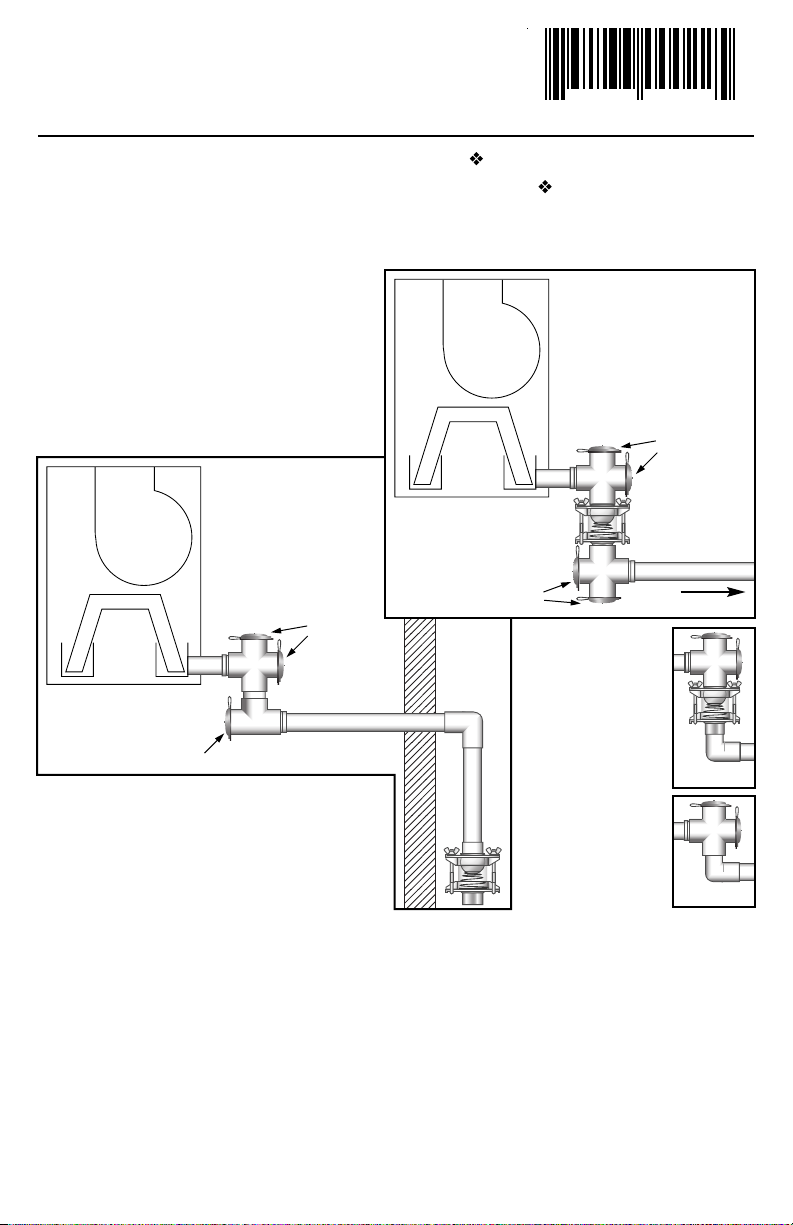
FIGURE 2
FOR POSITIVE OR NEGATIVE PRESSURE AIR HANDLERS/
PARA MANIPULADORES POSITIVOS O NEGATIVOS DE AIRE A PRESIÓN
MODEL EZT-150 CAPACITY .5 WG
1. Fit cross onto drain pan outlet of AC unit,then install trap as
shown in Figure 1 or Figure 2.
2. Trap must be installed vertically only, with float above spring as
shown. DO NOT INSTALL HORIZONTALLY.
3. Clean inlet Cross and drain pan outlet periodically with brush.
4. Clean trap and float periodically with soapy water by loosening
wingnuts until stirrup end of bolts can slip over retaining lips on
lower end cap, which, together with clear barrel can then be
separated from upper end cap. Float and spring can then be
removed for cleaning as required and interior surface of barrel can
be cleaned as well.
Fig. 1 and 2 show recommended configuration for
maximum access for cleaning.
Cross in Fig. 1 & tee in Fig. 2
on outlet side of trap can be
replaced with ell as in Fig.3 &
Fig.4 if space requires, but will
limit ability to clean & maintain
system.
La Fig. 1 y la 2 muestran la
configuración recomendada
para acceso máximo de
limpieza.
La cruz de la Fig. 1 y la T de la
Fig. 2 en el lado de salida de
la trampa pueden
reemplazarse por codos como
en la Fig. 3 y en la 4 si lo
necesita el espacio, pero esto
limitará la capacidad de
limpiar y mantener el sistema.
FIGURE 1
CLOSE COUPLED
INSTALLATION/
INSTALACIÓN
ACOPLADA CERRADA
DRAIN TO
OUTDOORS/
DRENAR HACIA
EL EXTERIOR
EXTERIOR
WALL/
PARED
EXTERIOR
AIR HANDLER – NEGATIVE
OR POSITIVE PRESSURE/
MANIPULADOR DE AIRE –
PRESIÓN NEGATIVA
O POSITIVA
AIR HANDLER – NEGATIVE
OR POSITIVE PRESSURE/
MANIPULADOR DE AIRE –
PRESIÓN NEGATIVA
O POSITIVA
REMOTE
INSTALLATION /
INSTALACIÓN
REMOTA PARED
EXTERIOR
FIGURE 3
CLEANING PORT/
ORIFICIO DE LIMPIEZA
CLEANING
PORTS/
ORIFICIOS DE
LIMPIEZA
CLEANING
PORTS/
ORIFICIOS DE
LIMPIEZA
CLEANING PORTS/
ORIFICIOS DE LIMPIEZA
INSTALLATION INSTRUCTIONS / INSTRUCCIONES DE INSTALACIÓN
Model
EZT-150
FIGURE 4
1. Encaje la cruz en la salida del recipiente de drenaje de la unidad
de aire acondicionado, luego instale la trampa como lo indica la
Figura 1 o la 2.
2. La trampa debe instalarse sólo verticalmente, con el flotador
sobre el resorte como se indica. NO LA INSTALE
HORIZONTALMENTE.
3. Limpie la cruz de la entrada y drene periódicamente la salida del
recipiente con el cepillo.
4. Limpie la trampa y el flotador periódicamente con agua jabonosa
soltando las tuercas mariposa hasta que el extremo de estribo de
los pernos pueda deslizarse encima de los rebordes de retención
en la tapa del extremo inferior,la cual, junto con el barril
transparente, puede separarse entonces de la tapa del extremo
superior.El flotador y el resorte pueden luego retirarse para
limpiarlos según se necesite; y también puede limpiarse la
superficie interior del barril.
5. Vuelva a armar insertando el resorte y el flotador dentro del barril
transparente, inserte la parte superior del barril en la tapa del
extremo superior,vuelva a enganchar el extremo de estribo de
los pernos y apriete manualmente las tuercas mariposa.
NO APRIETE EN EXCESO LAS TUERCAS MARIPOSA.
6. El Modelo EZT-150 UltraTrap puede adaptarse fácilmente con
un interruptor de flotador integral después de la instalación inicial.
También está disponible con interruptor de flotador listo de fábrica
(Modelo EZT-250).
7. Esta trampa debe instalarse según las instrucciones del fabricante
y respetando todos los códigos aplicables locales o nacionales de
plomería, drenaje y mecánica.
8. NUNCA CONECTE LA TUBERÍA DE DRENAJE DE
CONDENSADO DIRECTAMENTE EN UNA LÍNEA DE
ALCANTARILLADO. DEBE HABER UN ESPACIO DE AIRE
Y SELLO ENTRE LOS 2 SISTEMAS.
62233 0002275
EZT-150
 Loading...