

EZspyCam EPC-500 Series Instruction Manual
INSTRUCTION MANUAL
#EPC-500 Series
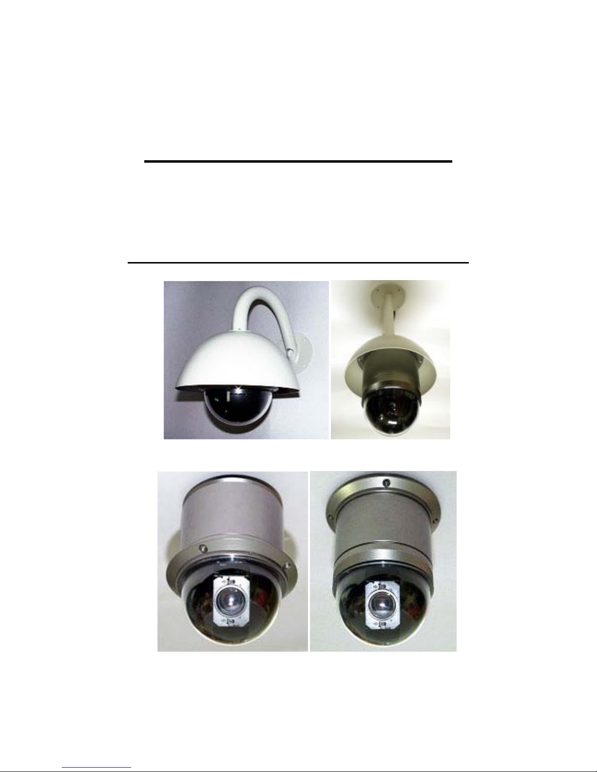
High-Speed Vandalproof Dome Camera
Outdoor Weatherproof Bracket
Indoor Surface Mount Indoor Surface Mount

Features
Camera Specification
• 1/4” Color CCD, 410 K Pixels
• MAX. 270 × /220x /160x with 10x Digital zoom
• Day & Night – Day True Color/Night-0.01 B/W (270x)
• Wide Dynamic Range Function
High Speed & Silent Motion
• MAX. 360˚/sec High Panning Speed and Continuous Rotation
• Silent with Very Little Vibration
• Simultaneous Pan/Tilt Interpolation Movement
High Accuracy & Long Life Cycle
• Adapted Blush-less DC Motor to Enhance Life Cycle
• Optical Encoder Feedback System for Accurate Control
Compact Design
• ∅130 Mini Dome Housing
PTZ Control
• RS-485 Communication, MAX 256 Multi-drop
• PELCO-D Protocol
Other Functions
• 128 Preset Points with Alphanumeric Label
• Auto Preset – Swing, Pattern, Group
• MIC. Input & Line Output for Audio Interface
2

SW 2 : Termination Resistance, Protocol, and Video Format Setting
• Termination Resistance: Pin 1
ON
12345
SW2
SW2:Protocol / Video Setting
NO.
Termination
Protocol
Video PAL
1 2 3 4 5
MIC. In / Audio Out cable
On
Off
The termination resistor is used for multi-drop connections
where two or more speed dome cameras are connected to a
controller on a communication line consecutively. Turn on
the termination resistance switch of both the nearest camera
and the farthest camera in the communication line.
• Protocol Setting: Pin 2~4
Pin 2 Pin 3 Pin 4 Protocol
Off Off Off PELCO-D
Others Reserved
• Video Format Setting: Pin 5
Pin 5 Video Format
Off NTSC
On PAL
MIC. cable
• MIC. In / Audio Out cable
Connector Description
3 Pin Terminal Connect to camera body
RCA yellow MIC. In
RCA white Line Out
• MIC. Cable
Connect MIC. Jack to MIC. In connector
3
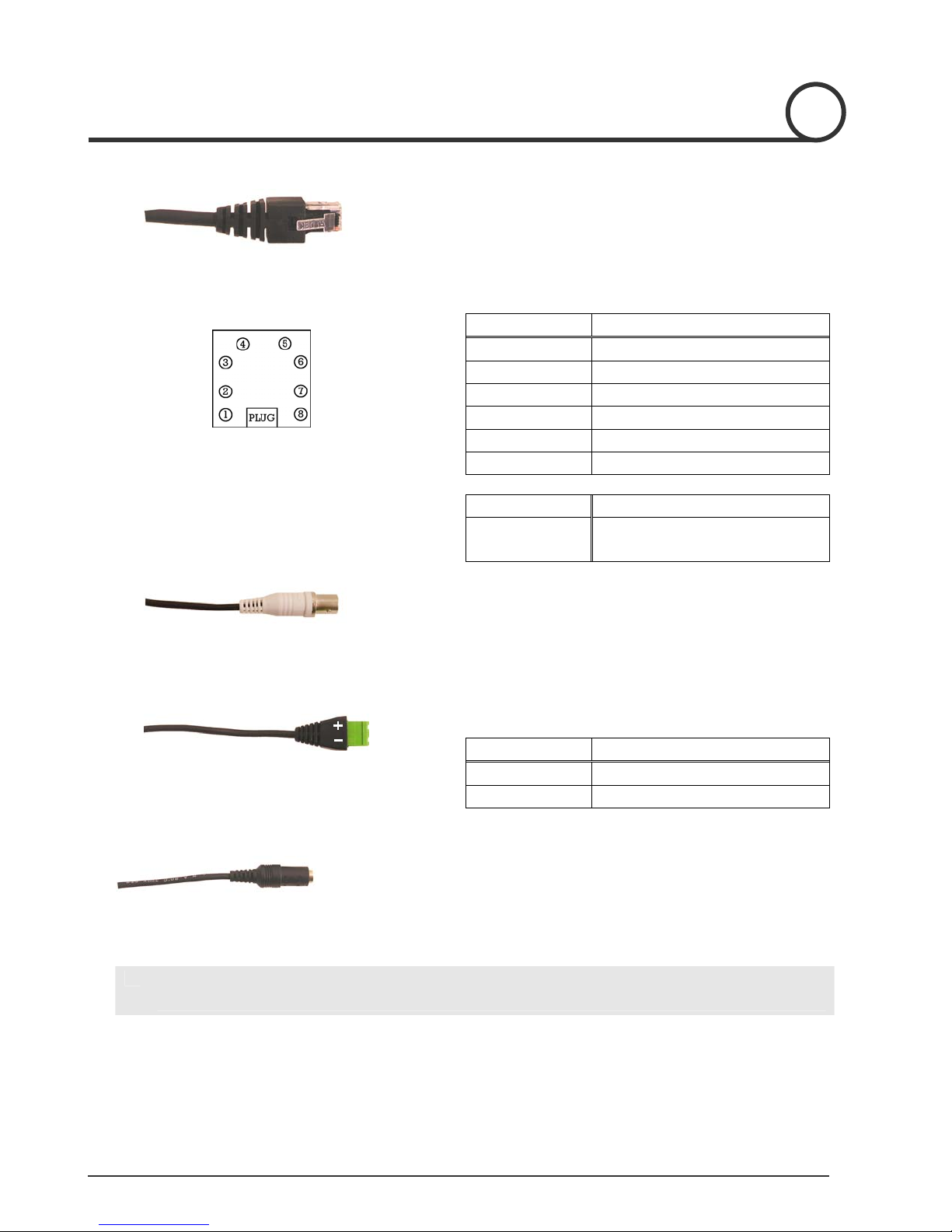
I/O Connector
• I/O Connector
Connect to I/O module.
I/O Module
BNC Connector for Video Out (Indoor)
• I/O Module
Pin Signal
1 Sensor Input 1 +
2 Sensor Input 2 +
3 Sensor Input Ground
4 Not Used
5,6 Relay Output 1
7,8 Relay Output 2
Sensor Input +5V, 10mA
Relay Output AC125V 0.6A Max
DC110V 0.6A Max
RS-485 Communication Connector (Indoor)
Power Connector (Indoor)
L
With Outdoor Housing, connect Power Input, Video Output, RS-485 cable to the PCB of
Outdoor Housing.
• Video out BNC connector
Connect to units such as monitor, VCR and etc.
• RS-485 Communication Connector
Connector Signal
+ D+
− D−
• Power Input Connector
Rated power input is AC 24V 1.5A. without Fan & Heater.
Rated power input is AC 24V 2A with Fan & Heater.
4
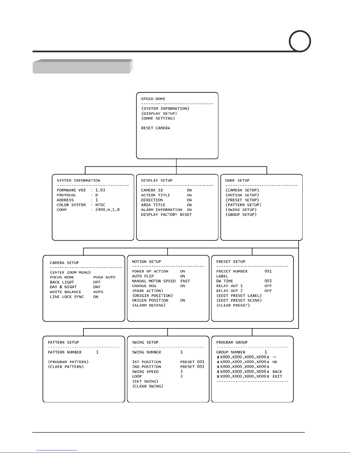
Setup Menu Structure
Main
MENU STRUCTURE
5

Zoom Camera Setup
MENU STRUCTURE
6

Motion Setup
MENU STRUCTURE
Preset Setup
7
MENU STRUCTURE
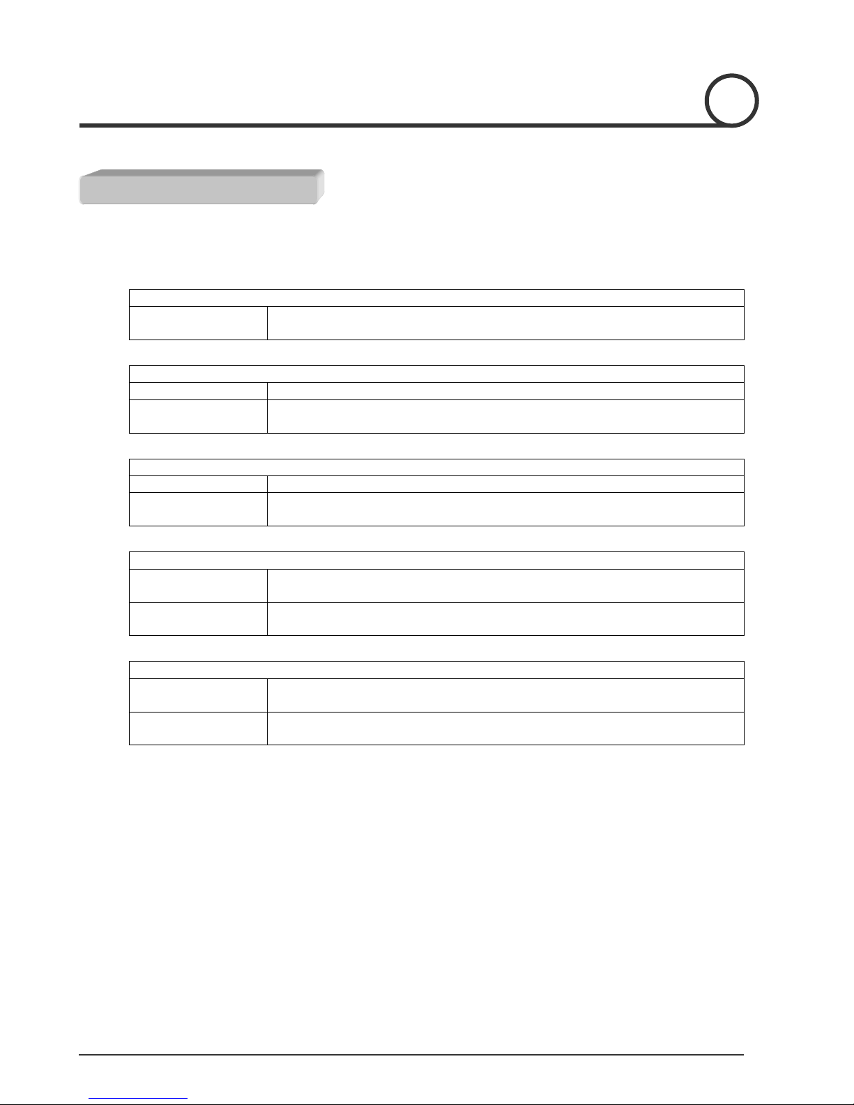
Macro
For ‘PELCO-D protocol version 5.0 or higher version’ controller user.
Menu
Enter Menu
Swing
Set Swing Enter Menu to set Swing function
Run Swing
Group
Set Group Enter Menu to set Group function
Run Group
Preset
Set Preset
Run Preset
Pattern
Set Pattern
Run Pattern
Enter Numerical Key 95 and Pattern key
[95] + [Pattern]
Enter Numerical Key 11~18 and Pattern key
[Number] + [Pattern]
Enter Numerical Key 21~28 and Pattern key
[Number] + [Pattern]
Key in 1 – 128 and hold Preset Key for more than 2 seconds
[Number] + [Preset] (More than 2 seconds)
Key in 1 – 128 and hold Preset Key for less than 2 seconds
[Number] + [Preset] (Less than 2 seconds)
Key in 1 – 4 and hold Pattern Key for more than 2 seconds
[Number] + [Pattern] (More than 2 seconds)
Key in 1 – 4 and hold Pattern Key for less than 2 seconds
[Number] + [Pattern] (Less than 2 seconds)
8
MENU DESCRIPTION
Key & Joystick Usage
• Menu heading in parenthesis ( ) contain sub-menu
• Use NEAR key to enter into sub-menu and use FAR key to return to upper menu
• Use JOYSTICK to scroll up & down the cursor in menu
• Use NEAR key to move the cursor at selection value location
• Use JOYSTICK to change the set value except CAMERA ZOOM MENU
• In CAMERA ZOOM MENU, Use NEAR or FAR key to change the set value
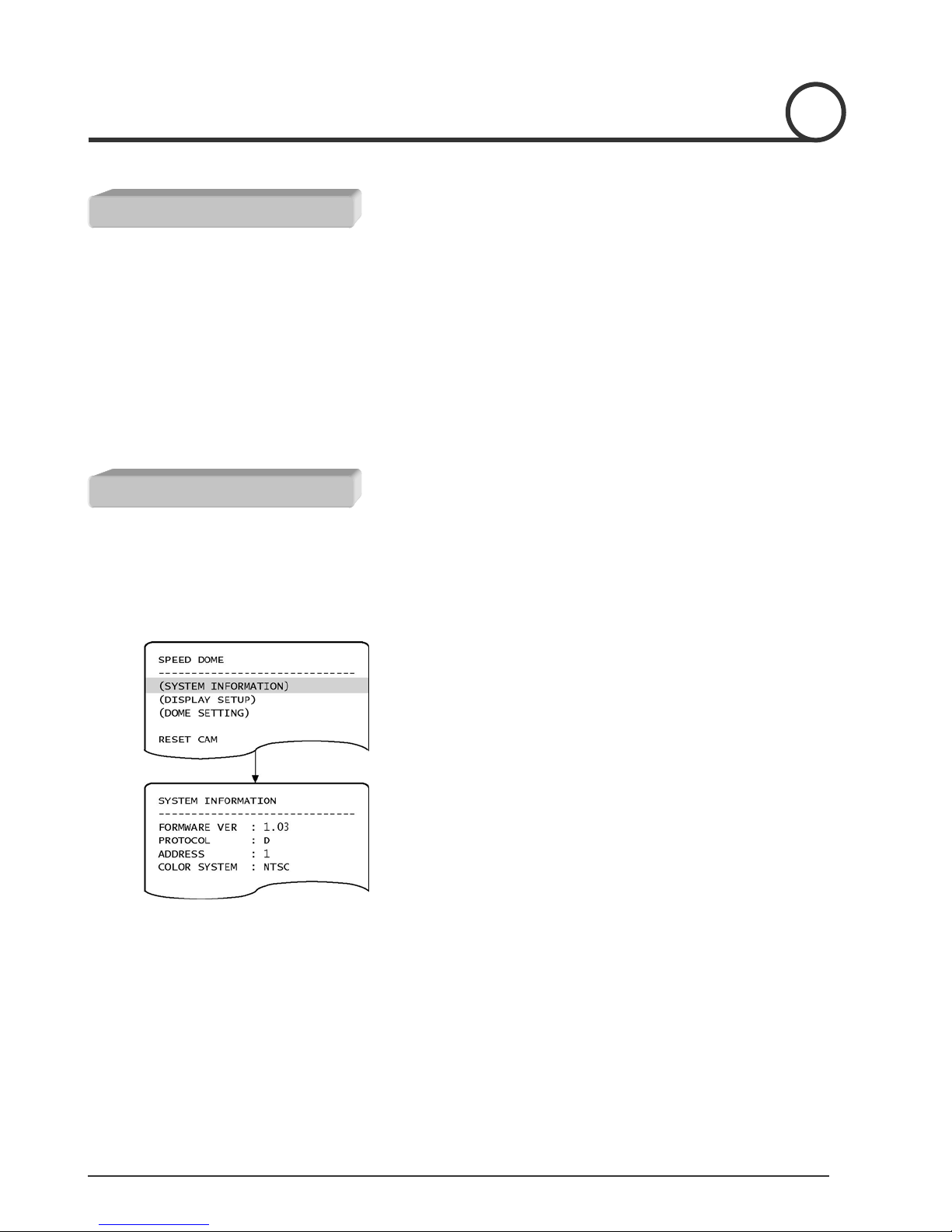
System Information Menu
L
Menu heading in parenthesis () contain sub-menu
• Shows System Information
1
○
2
○
Locate the cursor at (SYSTEM INFORMATION) menu
Press NEAR key to enter into sub-menu
9
 Loading...