

Page 1
1
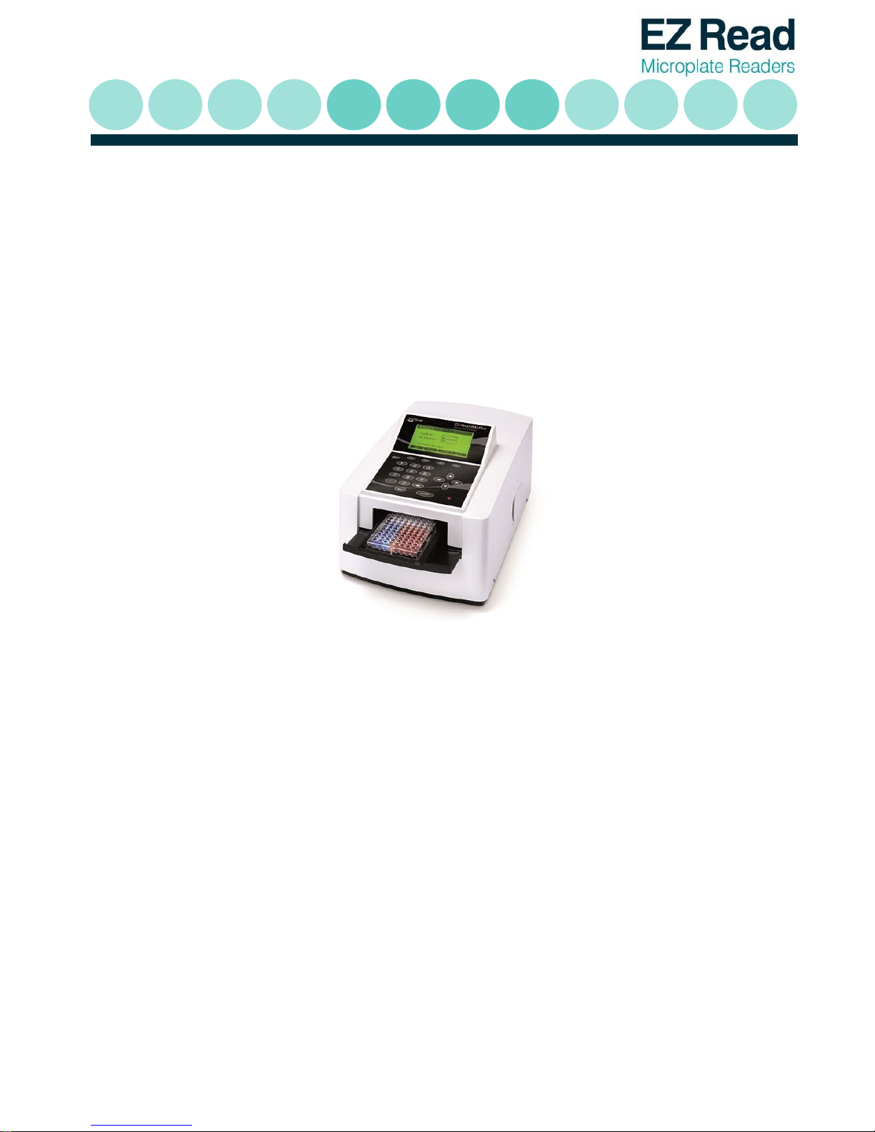
EZ Read 800 Plus Microplate Reader
User Manual
Biochrom Ltd
22 Cambridge Science Park
Cambridge
UK
CB4 0FJ
Tel.: +44/1223 423723
Page 2

2
Table of Contents
1. INTRODUCTION AND INTENDED USE ......................................................................................... .4
1.1 WHAT TO EXPECT FROM THE USER’S MANUAL .......................................................................................... 4
1.2 INTRODUCTION ................................................................................................................................... 4
2. INSTRUMENT USE ..................................................................................................................... 5
3. INSTRUMENT CONNECTION AND SOFTWARE INSTALLATION AND USE ......................................... 6
3.1 INSTRUMENT CONNECTION .................................................................................................................. 6
3.2 SOFTWARE INSTALLATION ..................................................................................................................... 6
3.3 QUICK MEASUREMENT ......................................................................................................................... 7
3.4 KINETIC MEASUREMENT ..................................................................................................................... 12
3.5 MULTI-WAVELENGTH MEASUREMENT .................................................................................................. 17
3.6 CALIBRATING THE INSTRUMENT .......................................................................................................... 20
3.7 USING THE USER INTERFACE ON THE EZ READ 800 PLUS......................................................................... 20
4. TECHNICAL INFORMATION ...................................................................................................... 39
5. GENERAL FEATURES ............................................................................................................... 39
5.1 MEASUREMENT MODES ..................................................................................................................... 39
5.2 INTEGRATED QUALITY CONTROL ........................................................................................................... 39
5.3 SCOPE OF SUPPLY .............................................................................................................................. 40
5.4 LIABILITY ......................................................................................................................................... 40
6. MAINTENANCE ...................................................................................................................... 40
6.1 APPROVED PARTS.............................................................................................................................. 40
6.2 CLEANING AND DISINFECTION ............................................................................................................. 40
Page 3

3
6.3 INSTRUMENT CLEANING ..................................................................................................................... 41
6.4 ADDITIONAL MAINTENANCE TIPS ......................................................................................................... 41
7. WARRANTY AND RETURN TO BASE .......................................................................................... 41
7.1 WARRANTY TERMS AND CONDITIONS ................................................................................................... 41
7.2 RETURNS TERMS AND CONDITIONS ...................................................................................................... 42
7.3 RETURNS PROCEDURE ........................................................................................................................ 43
8. ORDERING INFORMATION AND ACCESSORIES .......................................................................... 45
9. CONTACT INFORMATION ........................................................................................................ 45
9.1 TABLE 2 CONTACT INFORMATION ........................................................................................................ 46
10. APPENDIX ............................................................................................................................ 46
10.1 HELPFUL HINTS FOR SUCCESSFUL MICROPLATE ASSAYS ........................................................................... 46
10.2 TROUBLESHOOTING AND FREQUENTLY ASKED QUESTIONS ...................................................................... 46
11. DECLARATION OF CONFORMITY ............................................................................................ 49
Page 4

4
1 Introduction and Intended Use
1.1 What to expect from the user’s manual
Instrument use
Software installation
Quick start guides for operational use (to perform a quick measurement, kinetics and
multi-wavelength measurements).
A technical explanation of how the instrument operates
General features
Helpful hints for obtaining the best measurements using the instrument.
Maintenance
1.2 Introduction
What is a microplate reader?
A microplate reader is a used to measure the absorbance of liquid samples in a 96-welll plate.
What do microplate readers measure?
Microplate readers measure the amount of specific wavelengths of light that is absorbed by
molecules within a solution.
Why is this useful and how do microplate readers measure sample absorbance?
The amount of light absorbed by molecules within a sample is proportional to the sample
concentration as described by Beer-Lambert’s Law:
A = e c b
A= absorbance
e = molar absorptivity (Lmol-1 cm-1)
c = molar concentration (mol dm-3)
b = pathlength (cm)
Page 5

5
It is important to note that when measuring absorbance in a microplate well, the pathlength is
determined by the volume. In a microplate assay, it is very important that all wells have the same
volume and that all solutions are dispensed with an accurate liquid handler like an 8-channel pipette.
Common applications of absorbance-based microplate readers are ELISA, total protein (like Bradford
or BCA) and cell proliferation assays.
2 Instrument Use
The Biochrom EZ Read 800 Plus Microplate Reader is used for microplate-based applications
requiring endpoint or kinetic absorbance measurements from 400-750 nm in optically clear 96-well
plates with a standard SBS/ANSI footprint.
Only trained laboratory personnel should operate the Biochrom EZ Read 800 Plus Microplate
Reader. The Biochrom EZ Read 800 Plus Microplate Reader is intended for general laboratory and
research use only.
Page 6
6
3. Instrument Connection and Software Installation and Use
3.1 Instrument connection
1. Connect the USB cable from the PC to the instrument.
2. Connect unit using only the supplied power cords to a power outlet.
Please Note: Keep the area around the instrument free from clutter to allow for easy
access to the standard mains plug. This is also important to allow an adequate flow of air
around the instrument.
3. Switch on main switch (back of the instrument).
4. The power indicator light at the front of the unit will be illuminated when the instrument
is switched on.
3.2 Software installation
Galapagos is supplied with all EZ Read 800 Plus instruments. The software can be used to
control the microplate reader to measure all endpoint, kinetic and multi-wavelength assays.
1. To connect the instrument to a PC: Connect to the PC via the supplied USB cable.
2. To connect the instrument to Galapagos software: Insert the CD or USB supplied with
the instrument into a PC. Galapagos software includes pre-requisite files (dot.NET
Framework 4, Windows Installer and Microsoft SQL Express 2008) which allow installation
to occur. Insert the CD or USB and run the setup file. A pop-up menu will appear and
guide you through automatic installation.
Users can save results and templates to a Database. Galapagos uses a database to store
data in one place. This is useful for preventing data override and can allow easy data
transfer through communication with external laboratory database systems such as LIMS.
To create a Database, click ‘Setup’>’Select Database’>’Galapagos’. Alternatively users can
click on ‘Add Database’ and enter a new database.
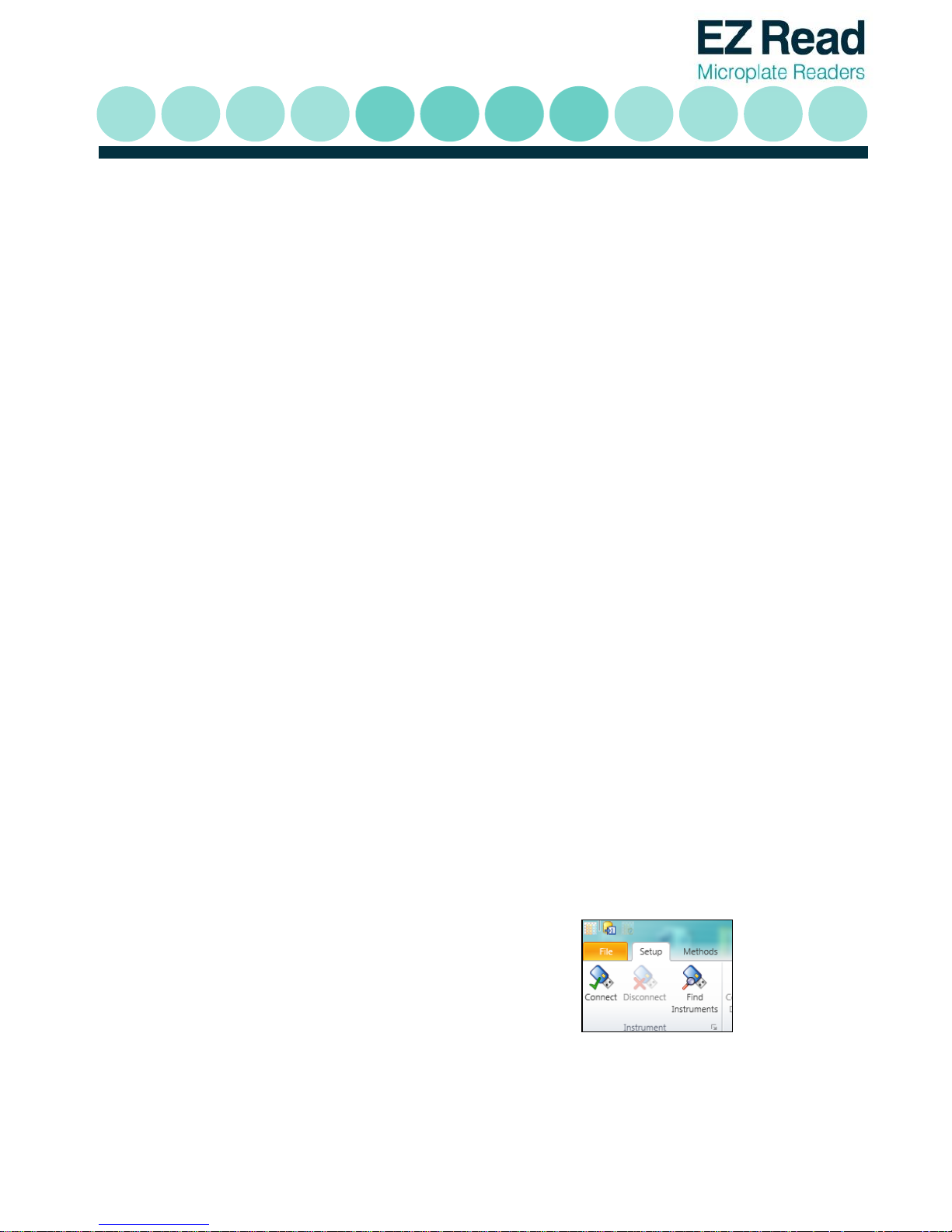
Connect the instrument to a computer or
laptop. Connect by clicking the Galapagos
icon and click on the ‘Find Instruments’
icon which detects the connected
instrument. For subsequent use, users can
click the ‘Connect’ icon for recognition:
Page 7
7
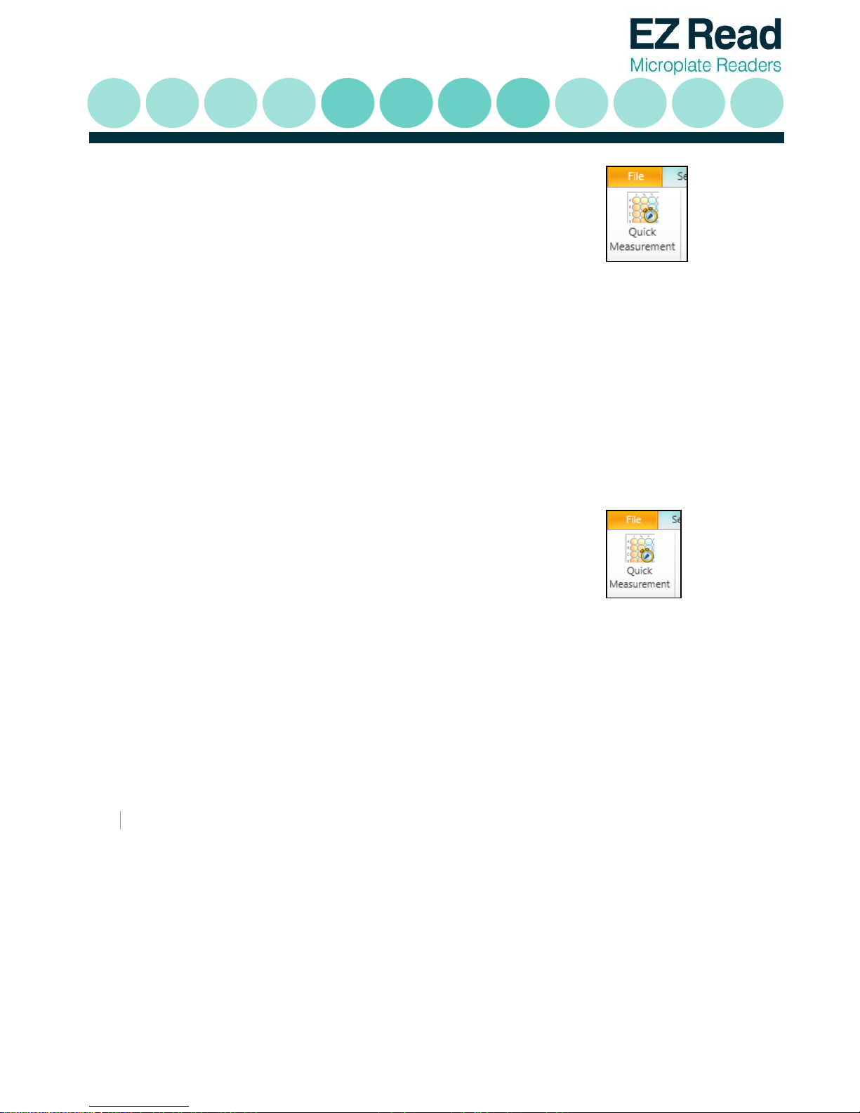
3. Click ‘Quick Measurement’:
4. The microplate reader is now ready for use.
3.3 Quick Measurement:
Performing a Quick Measurement on Galapagos:
1. Click the ‘Quick Measurement’ icon on the main menu screen:
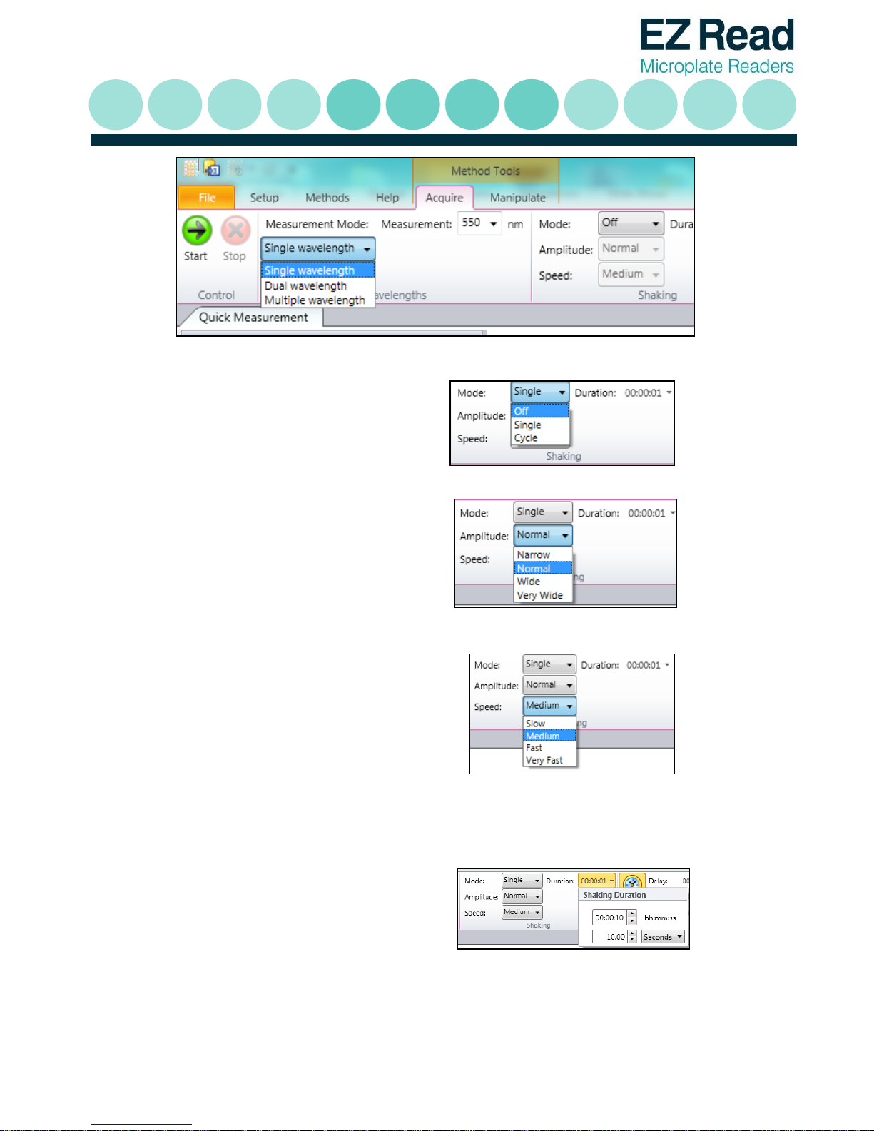
2. Select the appropriate measurement mode (Single, Dual or Multi-wavelength):
wavelength is where the sample of interest absorbs. The second wavelength is used as
a reference and will be subtracted from the first wavelength. The absorbance
measurement is then subtracted from a measurement at a different wavelength.
Multiple wavelength refers to a series of absorbance measurements at different
wavelengths. In this mode, absorbance measurements are not subtracted from one
another.
Page 8
8
3. Users can also select to shake the
microplate. Users can select shaking to
be a single event or in timed cycles.
4. Select the amplitude (degree of linear
shaking).
5. Select the speed for linear shaking.
6. Users can select the duration of
shaking.
Page 9
9
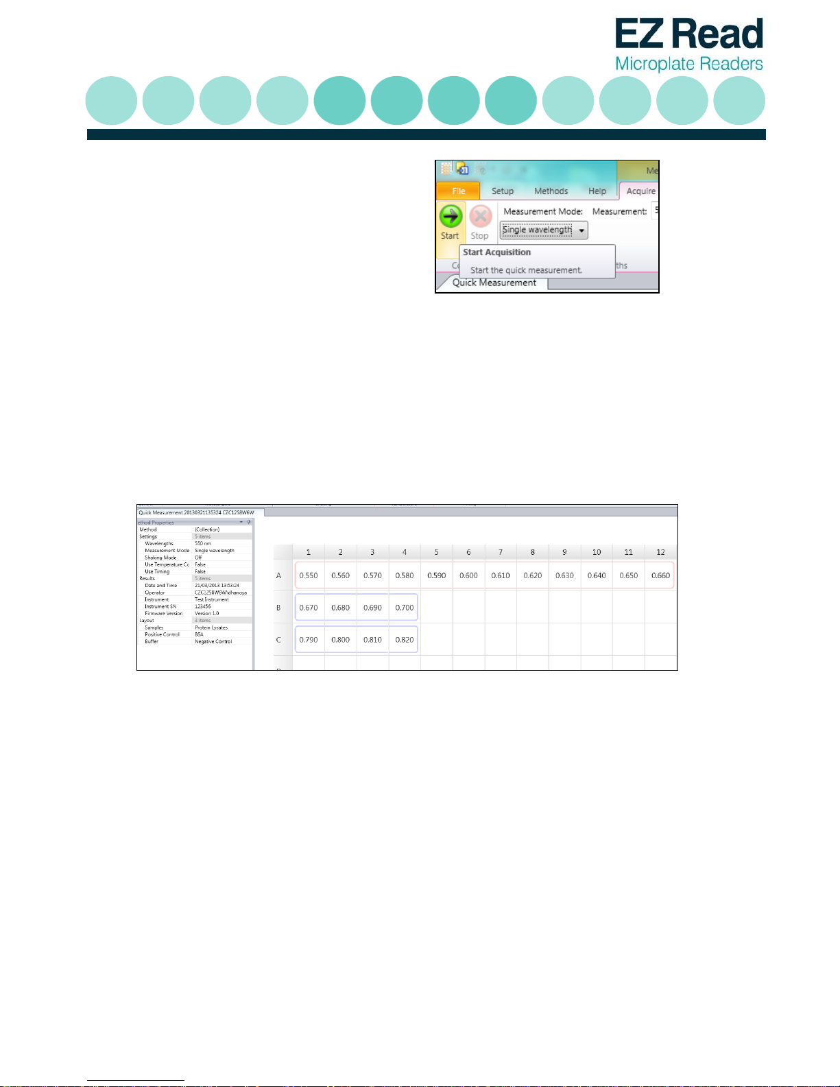
7. Click ‘Start’ to begin acquisition.
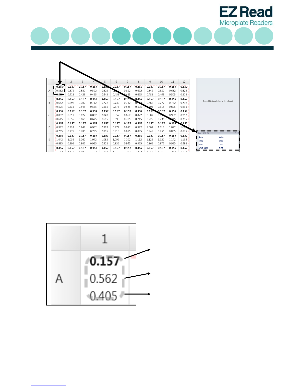
8. Raw absorbance values for dual wavelengths measurements are displayed in the wells. Details
of corresponding wavelengths can be displayed when clicking on the individual well.
Page 10
10
9. When users click onto a well, it is highlighted (dashed lines). In regards to dual wavelength
measurements, three absorbance values are displayed.
The bold value refers to the absorbance
measurement after wavelength
subtraction of the absorbance at the
measurement wavelength from the
absorbance at the reference wavelength.
The second value is the absorbance at
the measurement wavelength
The third value is the absorbance at the
reference wavelength.
Page 11
11
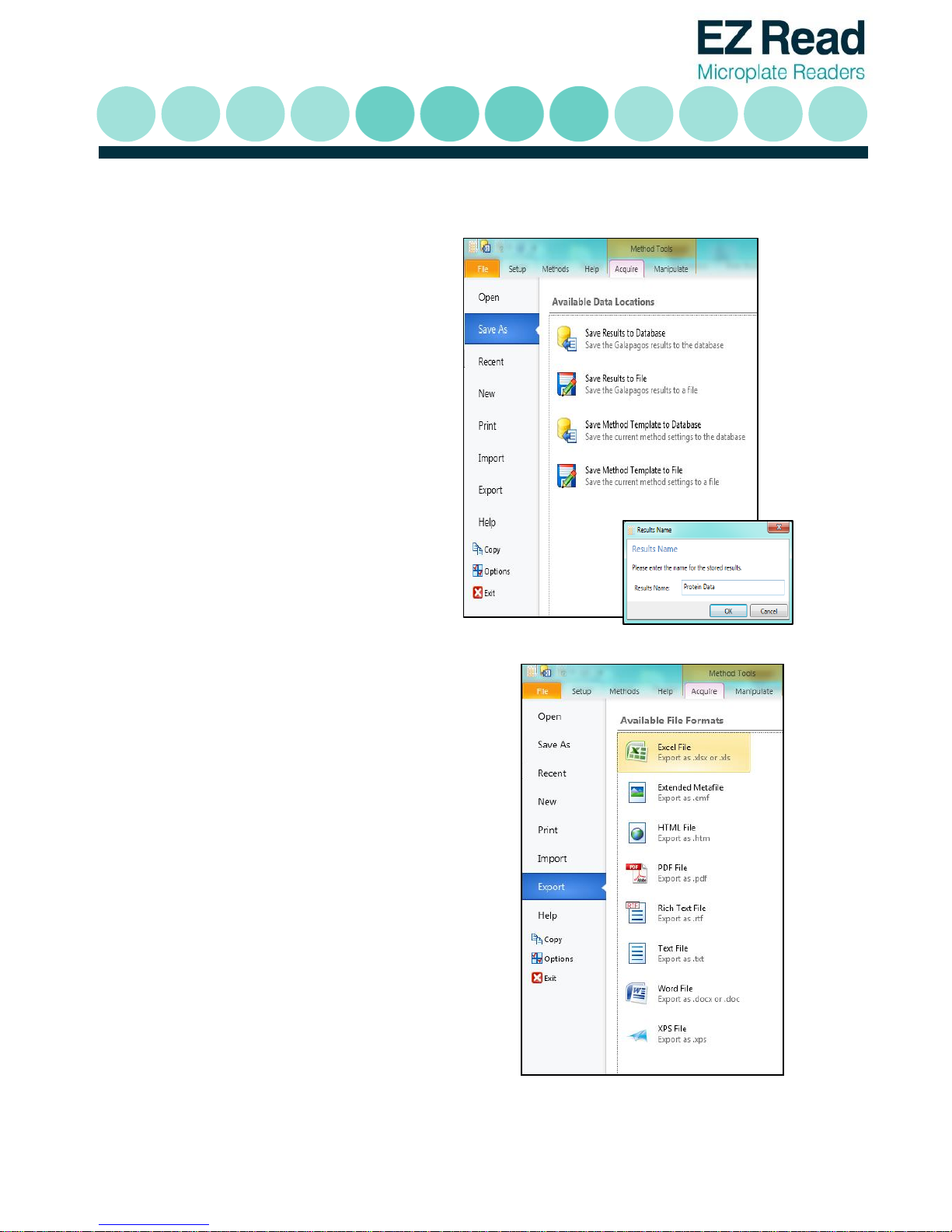
10. Results can be saved to ‘Database’. A
database is useful for saving, sharing and
extracting data via communication with
an external database system such as
LIMS. Users can save files and templates
onto the database, ‘File’ (save to own
personal file), or ‘Save Method
Template’ (saves the method protocol
for future use).
11. Results can also be exported as Excel, Extended
Metafile, results exported as a HTML file, PDF,
Rich Text File, Text File, Word File and XPS File.
Page 12
12
3.4 Kinetic Measurements
Performing a kinetic measurement on Galapagos:
Kinetic measurements refer to recorded measurements over the course of a set time period. To
perform a kinetic measurement, open Galapagos as mentioned in section 3.2.
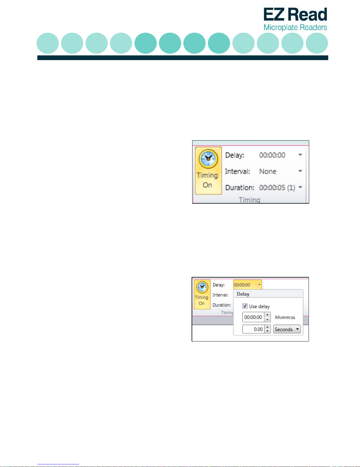
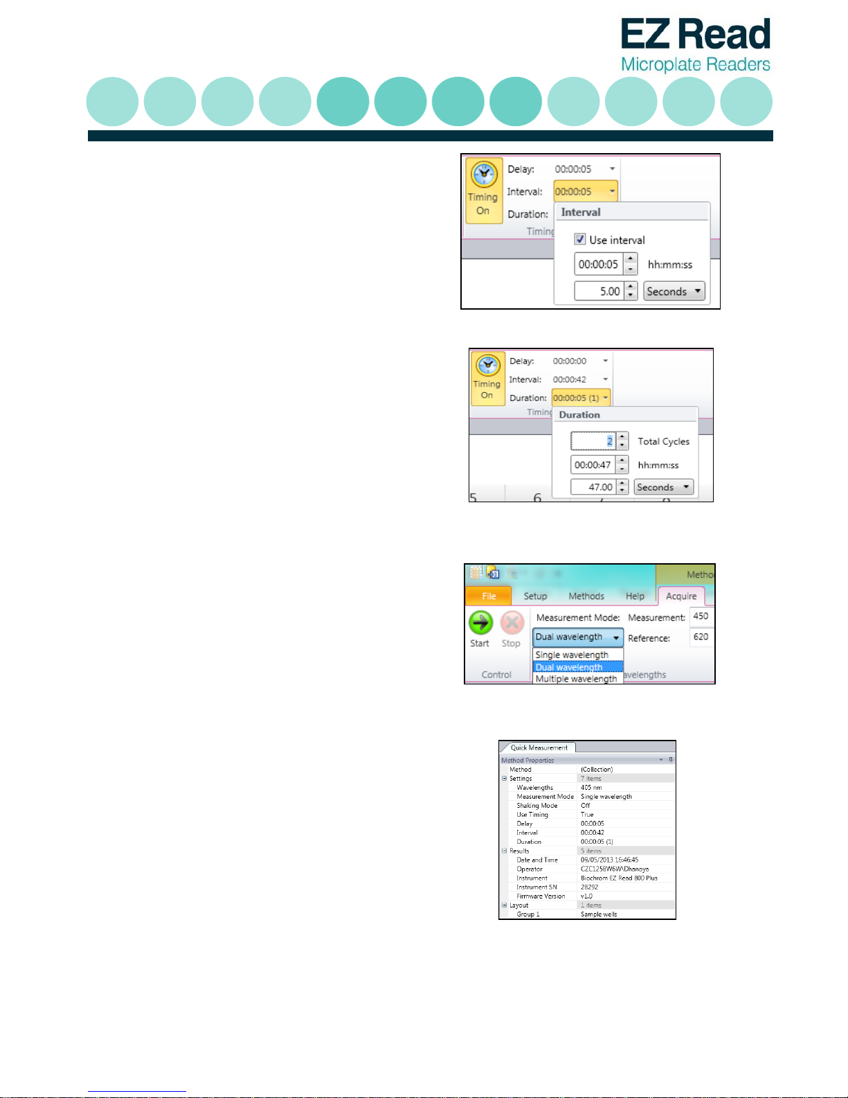
1. For kinetics measurements, click on the
timer icon for timed measurements. This is
indicated by ‘Timing On’
Users can then input the required kinetic parameters for a measurement cycle. The measurement cycle
refers to the point of absorbance measurement including any timed delay and/or interval until the next
reading.
Note: the use of a delay is optional (tick or un-tick), whereas the interval and the number of cycles is
not.
2. Users can input delays between
measurements.
Page 13
13
3. Users can input timed intervals between
readings.
4. The measurement cycle (delay and interval)
can be inputted and multiple cycles can be
selected.
5. Select either: Single, Dual or Multiple
wavelength modes. Note: measuring at
more than one wavelength will affect the
interval that can be used. The interval time
must take into account the measurement
time at a single wavelength (e.g. this is 5
seconds at a single wavelength for the EZ
Read 800 Plus).
Note: Method details of the kinetic experiment are
listed on the left-hand panel of the screen.
Page 14
14
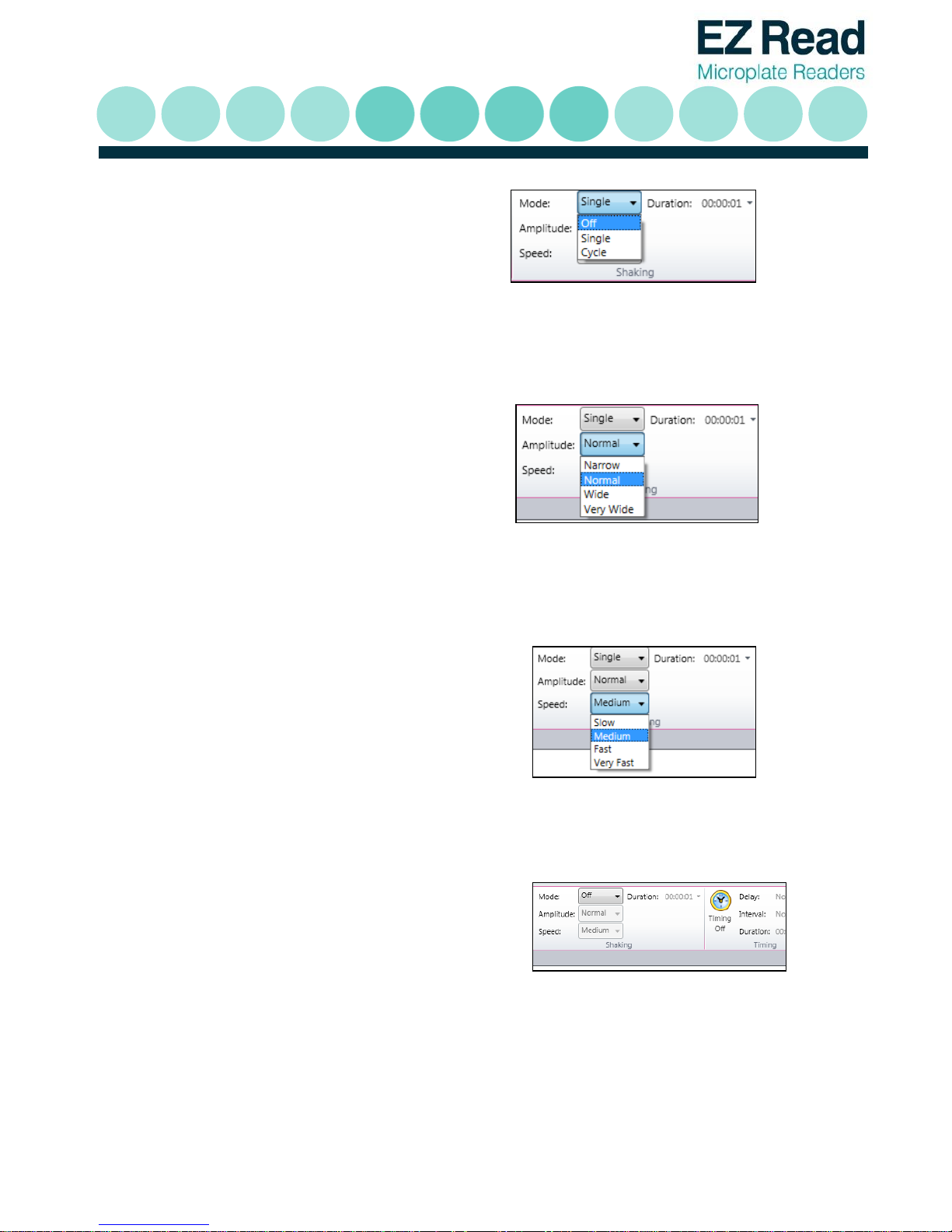
6. Users can also select to shake the
microplate. Users can select shaking to be a
single event or in timed cycles.
7. Select the amplitude (degree of linear
shaking).
8. Select the speed for linear shaking.
9. Users can select the duration of shaking.
Page 15
15
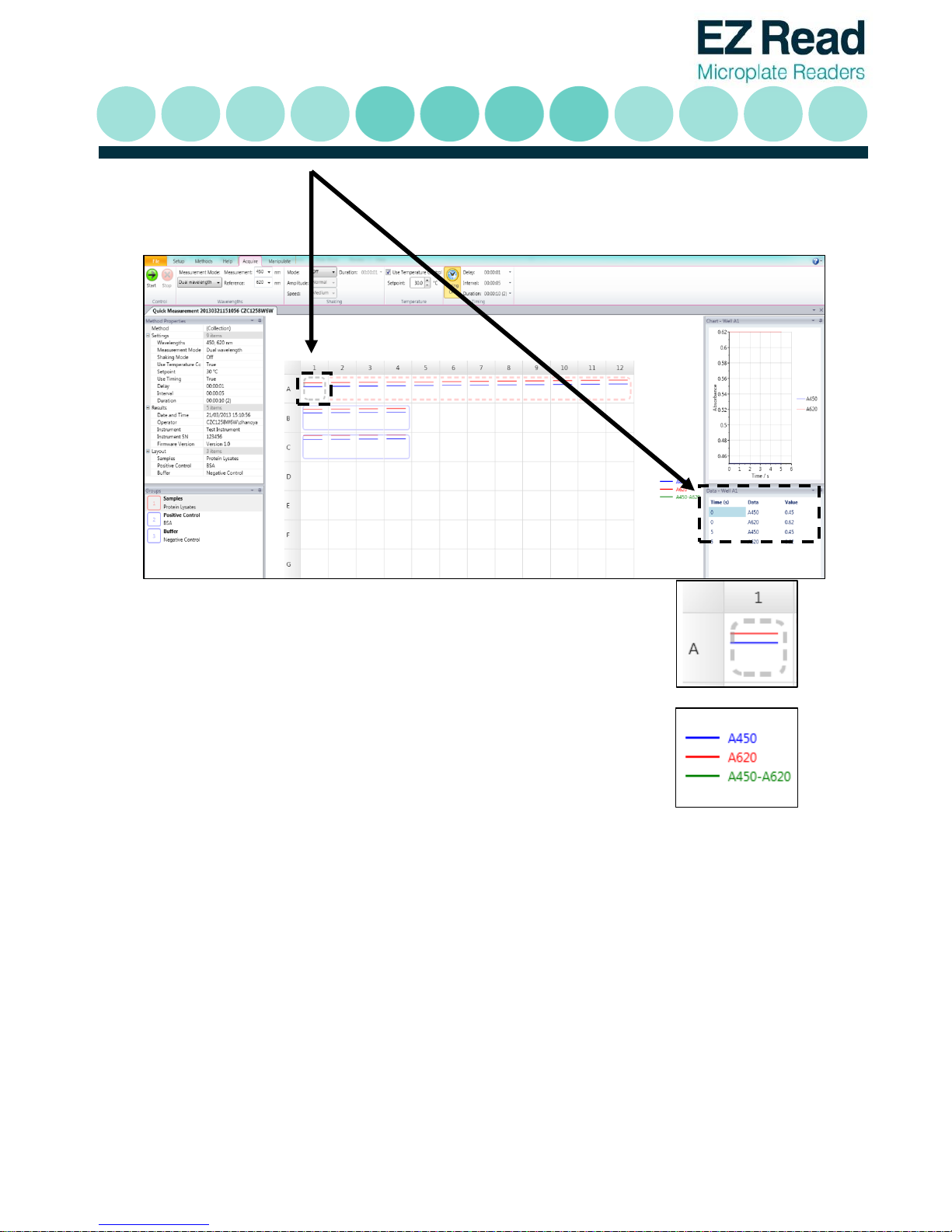
The lines shown in each well refer to the measurement at one
wavelength over time. Different wavelengths used for absorbance
measurements are assigned a specific colour and identified by a
legend.
Page 16
16
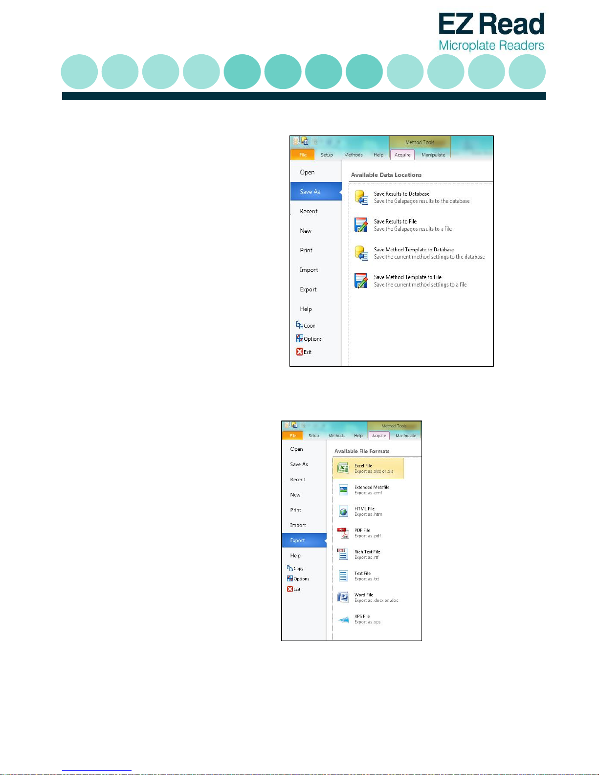
10. Results can be saved to
‘Database’. A database is useful
for saving, sharing and
extracting data via
communication with an
external database system such
as LIMS. Users can save files
and templates onto the
database, ‘File’ (save to own
personal file), or ‘Save Method
Template’ (saves the method
protocol for future use).
11. Results can be exported as
Excel, Extended Metafile,
results exported as a HTML file,
PDF, Rich Text File, Text File,
Word File and XPS File.
Page 17
17
3.5 Multi-wavelength Measurements
Performing a multi-wavelength measurement on Galapagos:
The Multiple wavelength application allows users to measure absorbance at different
wavelengths. Mathematical manipulations of this data can often reveal information about the
sample's composition or purity.
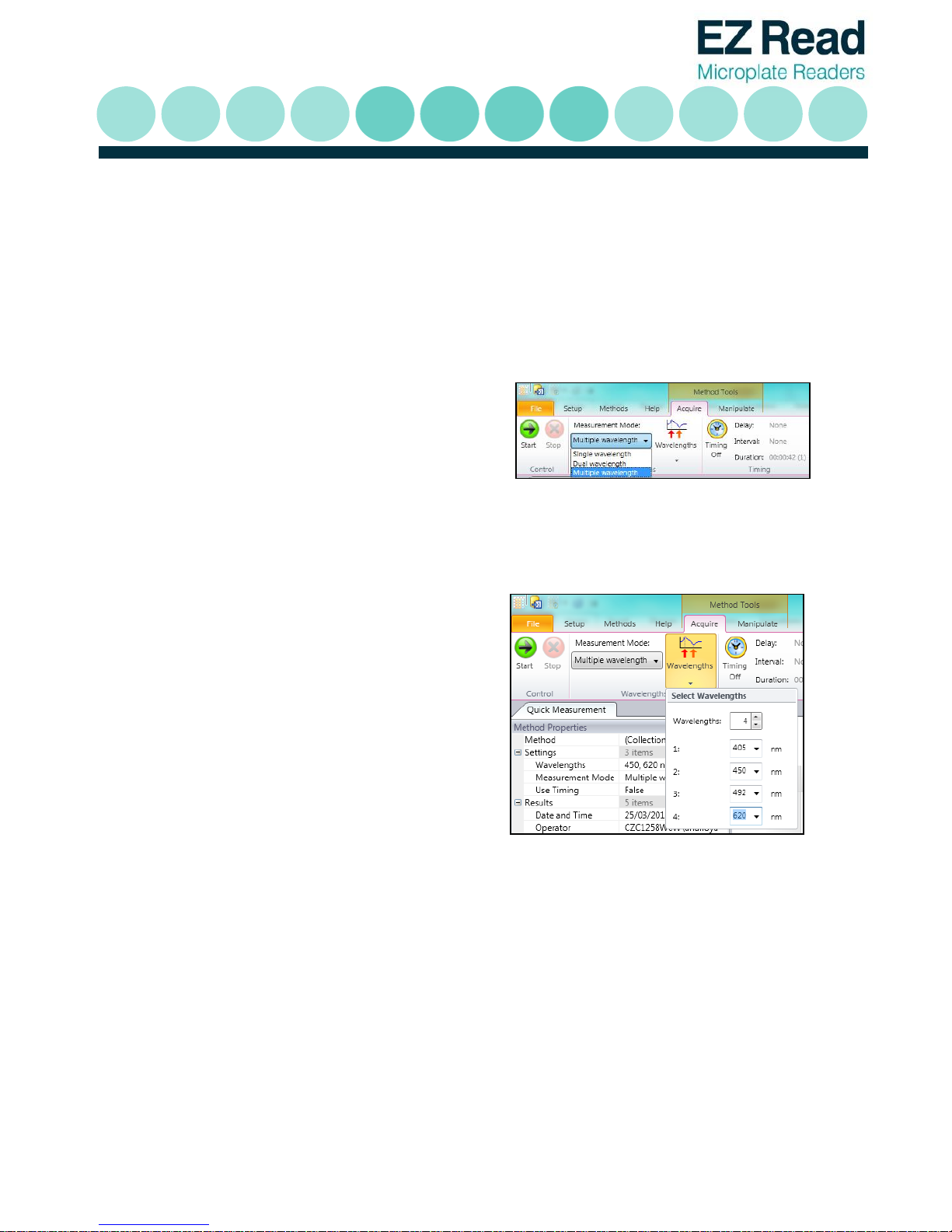
1. To perform a multi-wavelength
measurements click ‘Multiple
Wavelength’ from the drop down
menu.
2. The menu is adjusted to allow users
to select up to 4 wavelengths for
measurement. Each wavelength
must be different. For the EZ Read
800 Plus ELISA, users can input
wavelengths of 405, 450, 492 and
620nm. For the EZ Read Research
model, users can choose four
wavelengths from 405, 450, 492,
562, 595 and 620nm. Click ‘Start’ to
begin the measurement.
Page 18
18
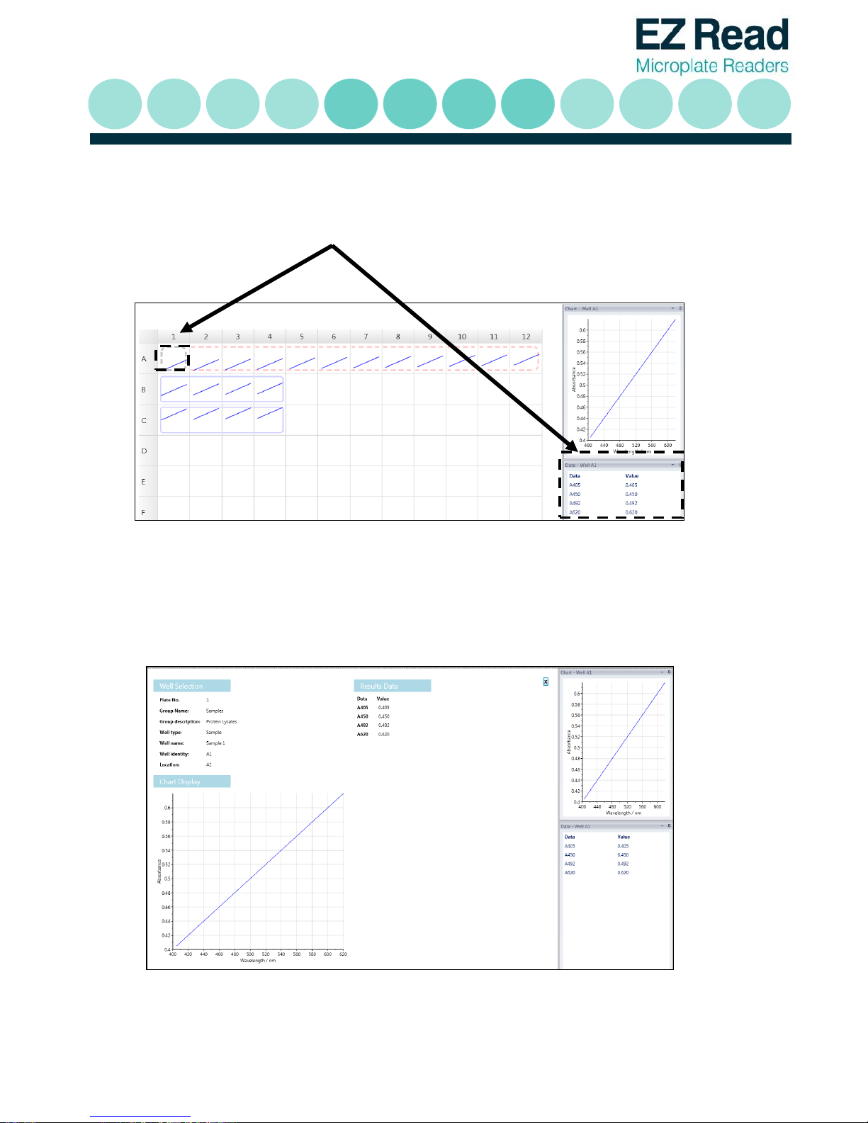
3. Individual multi-wavelength measurements are displayed in each well, with raw absorbance
displayed on the right hand panel as a graph of absorbance vs. wavelength.
4. Alternatively users can click on an individual well to view the scan in more detail and raw
results. Both tabulated and graphical chart data are displayed.
Page 19
19
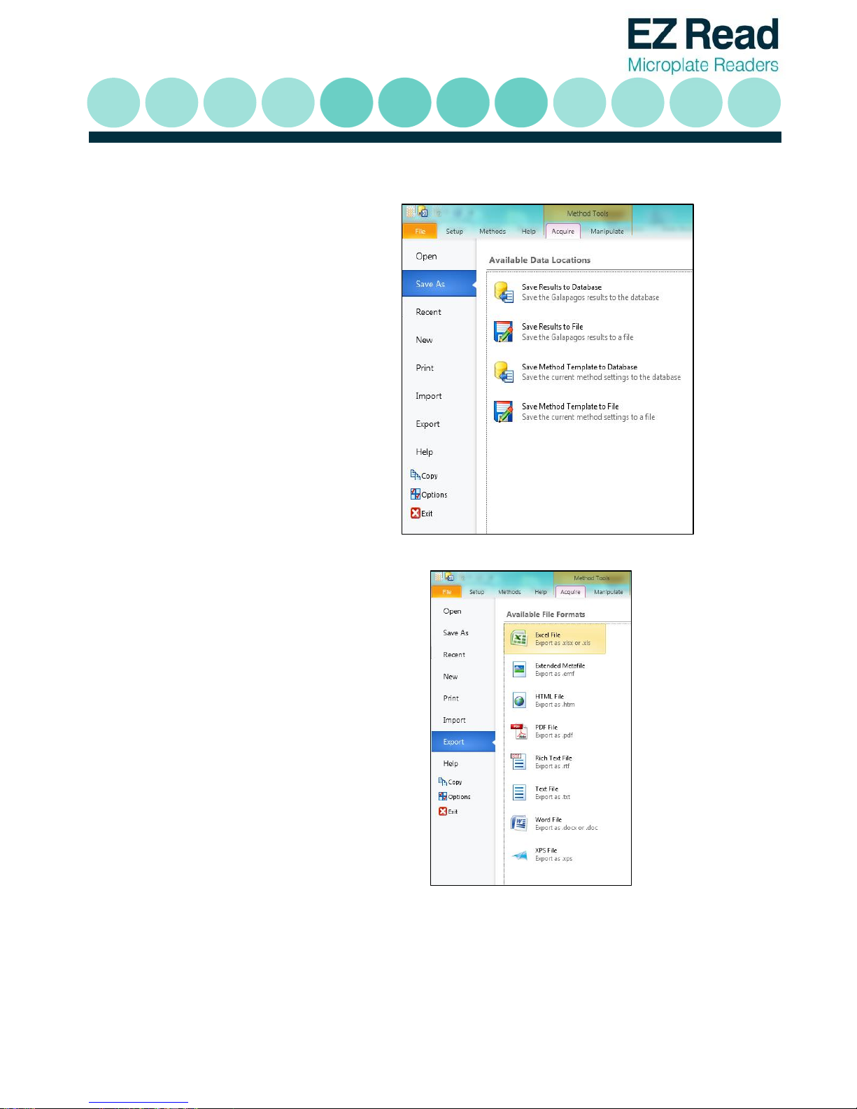
5. Results can be saved to
‘Database’. A database is useful
for saving, sharing and
extracting data via
communication with an
external database system such
as LIMS. Users can save files
and templates onto the
database, ‘File’ (save to own
personal file), or ‘Save Method
Template’ (saves the method
protocol for future use).
6. Results can also be may be
exported as file types such as
Excel, Extended Metafile,
results exported as a HTML file,
PDF, Rich Text File, Text File,
Word File and XPS File.
Page 20
20
3.6 Calibrating the instrument
The EZ Read 800 Plus performs an automatic calibration of the lamp energy before it measures a
microplate; however, the user may use a calibration plate containing a series of neutral density
filters with known optical density to verify reader performance. See Section 8: Ordering for order
details.
3.7 Using the user interface on the EZ Read 800 Plus
The 240 x 128 pixel high resolution, graphical liquid crystal display provides the user with set up
parameters and experimental results. The keypad is used for navigation and has a spill-proof
membrane. Navigation using the on-board menu is very simple:
1. Press the corresponding number on the
keypad to enter the user mode choices or
numeric data.
2. Press keypad directly below the corresponding option on the display (F1, F2, F3 and F4) to select
the appropriate option.
3. Use the four cursor keys to navigate around the options when the prompts appear.
4. Use the enter key to move forward to the next display page.
5. Use the ESC key to go back to the previous screen.
EXPERT PLUS
Page 21
21
6. Incorrect entries can be removed using the key.
7. The keypad can be locked to prevent unauthorized access. (default PIN is 1505). Service engineers
can access service functions from here by entry of a specific PIN.
3.7.1 Description of the main menu options
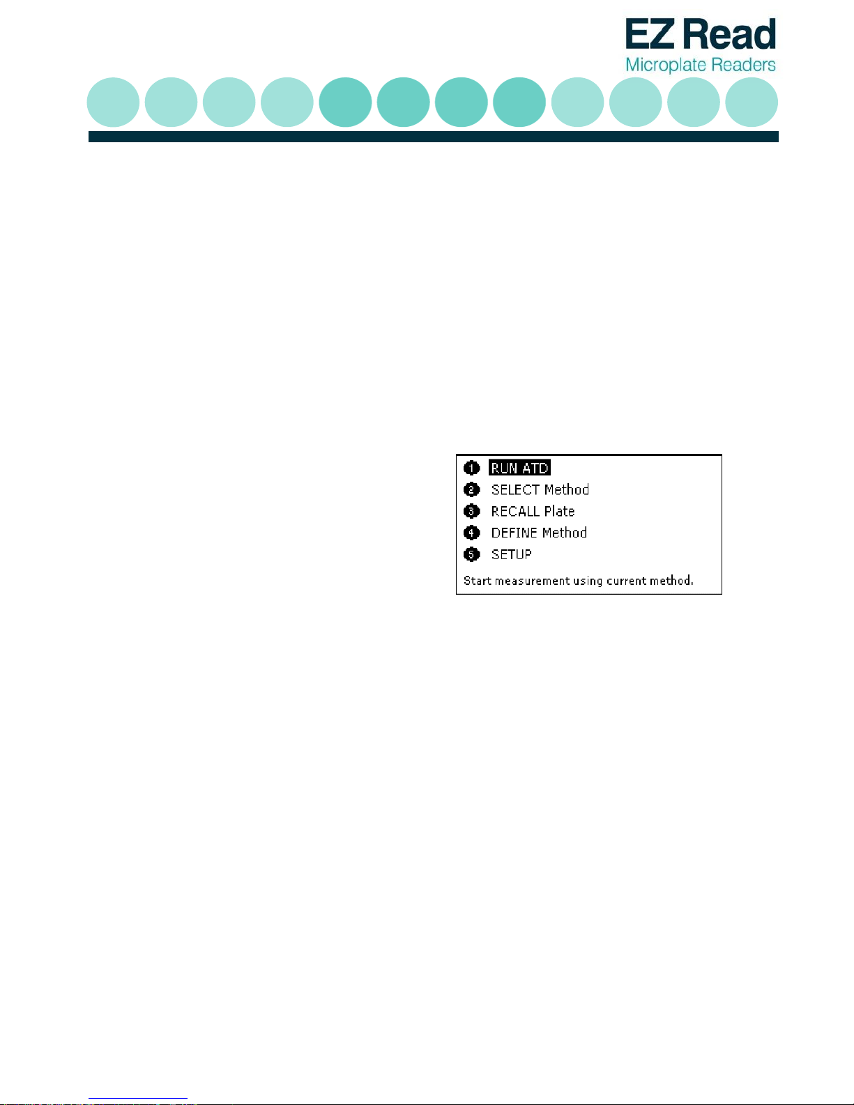
1. Run
This option starts a measurement with the last used or defined
method.
2. Select Method
This option selects a pre-defined or previously stored method
to use.
3. Define Method
This option enables a new method to be defined (Method
Definition), either from the beginning or by modification of a
previously stored or default method.
4. Recall Plate Data
This option recalls previously stored measurement data.
5. Setup
This option enables the basic plate reader parameters, such as
printer driver and filter set up/calibration, to be set up.
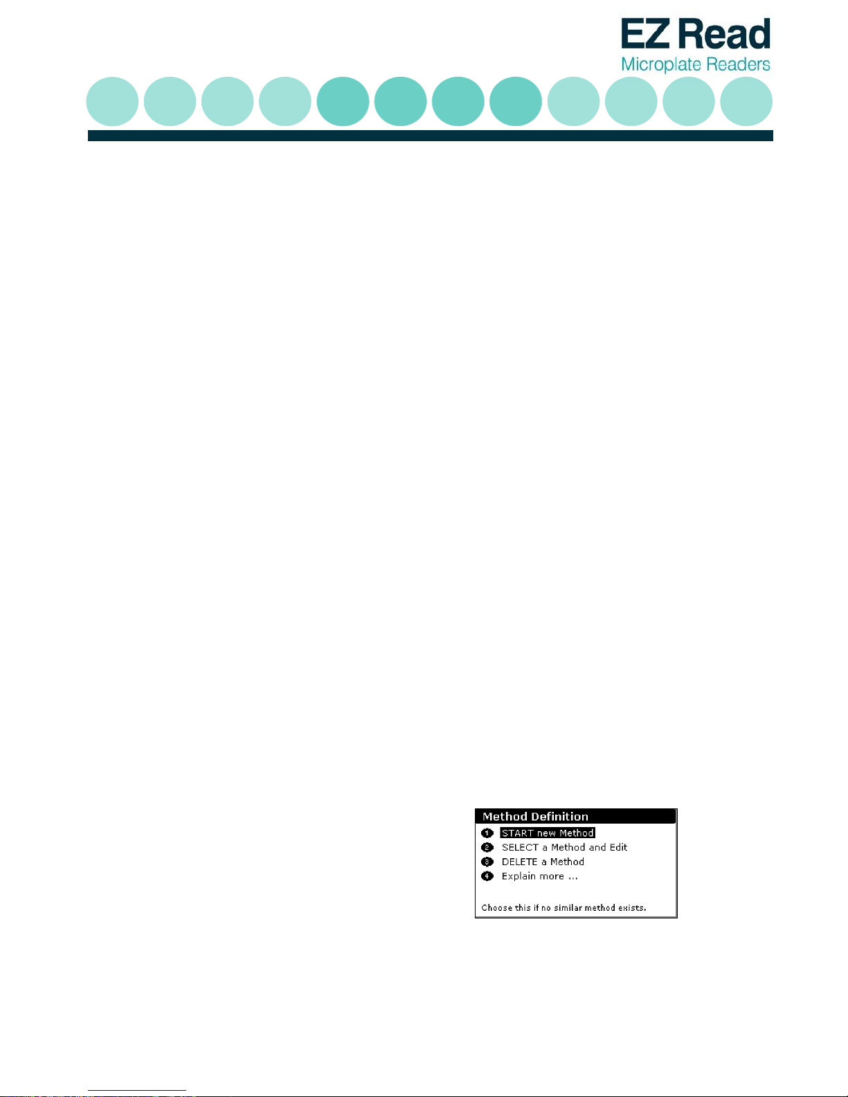
3.7.2 Method Definition
The method definition submenu offers three
choices. These include:
Define a new method.
Edit an existing method which can replace
an original method or stored using a new
name.
Delete an existing method.
Page 22

22
3.7.2.1 Method Definition: Filters
1. Measurement
Use the keys to select the filter to be used for
measurement.
2. Reference
Use the keys to select the filter to be used as a reference.
Select “none” for no filter. The reference value (usually
620nm), is subtracted from the measured value to correct for
imperfections etc. on the plastic microplate; these can have a
great effect on low OD measurements.
3. Shake
Press F2 if plate shaking is required before measurement.
This is often used when working with cells in order to prevent
samples from settling on the bottom of the well. Enter the
shaking time required in seconds and the degree of shaking.
The options are: slow / medium / fast / very fast and a
combination of speed and travel distance. Press F4 to accept
the entries.
4. Kinetics
Press F4 if kinetics is required. Enter the interval time (time
between readings) and the number of measurements. The
total process time is calculated and indicated on the screen.
The minimum interval time is 10 seconds and the maximum
number of measurements is 100.
NOTE: Up to 100 plate data results can be stored in the instruments memory. If during the kinetic
measurement the maximum capacity is reached the new results will overwrite the results stored first.
When previous measured data should be kept, save these data with the Connect Plus program.
Press F4 to accept the entries.
Press enter to move to the next method definition box.
3.7.2.2 Method Definition: Layout (for controls and standards)
1. Options
Press F3 to define default directions (horizontal or vertical)
for replicates of controls and for samples. Move the
symbol to the desired option with the up / down arrow keys.
Select the option by pressing either the left or right arrow
Page 23
23
key. Press F4 to accept the entries.
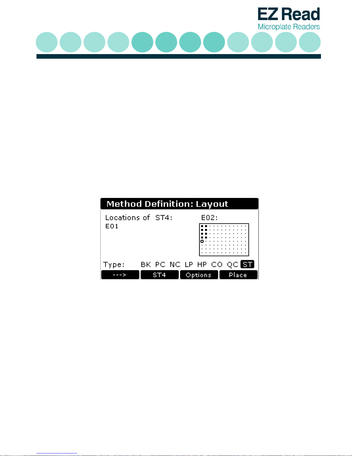
2. Choose well definition
Press F1 ‘--->’ to select the well type required from the
options listed at the bottom of the display box. With the
exception of BK and ST the terms are names and whatever
you want them to be. They are not “tied”.
For example, LP and HP can be used to substitute for terms
T1 and T2 defined in a specific test kit. The terms can be used
in calculations defined later in the method definition.
BK Blank
The absorbance of the blank value(s) is automatically
subtracted from the absorbance of the other wells.
NC
Negative control
Used for qualitative / screening tests.
PC
Positive control
Used for qualitative / screening tests.
Page 24

24
LP
Low positive
Used to see if results are outside pre-defined limits
HP
High positive
Used to see if results are outside pre-defined limits
CO
Control
Use as required.
QC
Quality control
Use as required.
ST
Standards
Use for quantitative determinations; a maximum of 16
standards can be used.
3. Placement
Press F4 to place the required well type at the location
shown on the display. Enter replicates by repeat pressing of
F4 as appropriate. By alternating between F1 and F4 it is
possible to build up the plate as required. You can come
back to edit the layout if required. Use the arrow keys to
move around the plate layout. Above the plate illustration
the current position and well type is shown.
4. Standards
When ST (standards) is selected, ‘ST1’ option appears as F2.
After placing these on the layout, press F2 to get ST2. A
total of 16 standards, with replicates, can be built up in this
way. When doing standards, note that the concentrations
are entered later on.
5. Press enter to move to the next method definition box.
Page 25

25
3.7.2.3 Method Definition: Samples
Samples can be placed either individually by moving the cursor to the desired location. Alternatively all
wells not already used can be filled with samples. Replicate samples can be used in combination with
single samples when desired. There is no limit on the replicate number.
1. Options
Press F3 to define default directions (horizontal or vertical)
for replicates of samples and for different samples. Move
the symbol to the desired option with the up / down
arrow keys and select the option by pressing either the left
or right arrow key. Press F4 to accept the entries.
2. Place samples
Place the first sample (SM1) and replicates using F4. Press
F1 to get SM2. Use F4 to place the second sample and
repeat as necessary. Replicates of samples can be placed in
any free location; it is not necessary that the wells are
adjacent.
3. Fill all
To reproduce the first sample pattern for all samples:
Sample 1 has to be defined. The Function ‘Fill All’ (F2) will
fill the plate accordingly as set in ‘Options’.
4. To erase all already defined sample positions press the Backspace () for a few seconds.
5. Press enter to move to the next method definition box.
3.7.2.4 Method Definition: Standards
In case standards have been defined in the layout section, the calibration screen appears.
Use this option to enter the values of the standards in addition to the units for the concentration and to
choose the curve-fit method (model).
Page 26
26
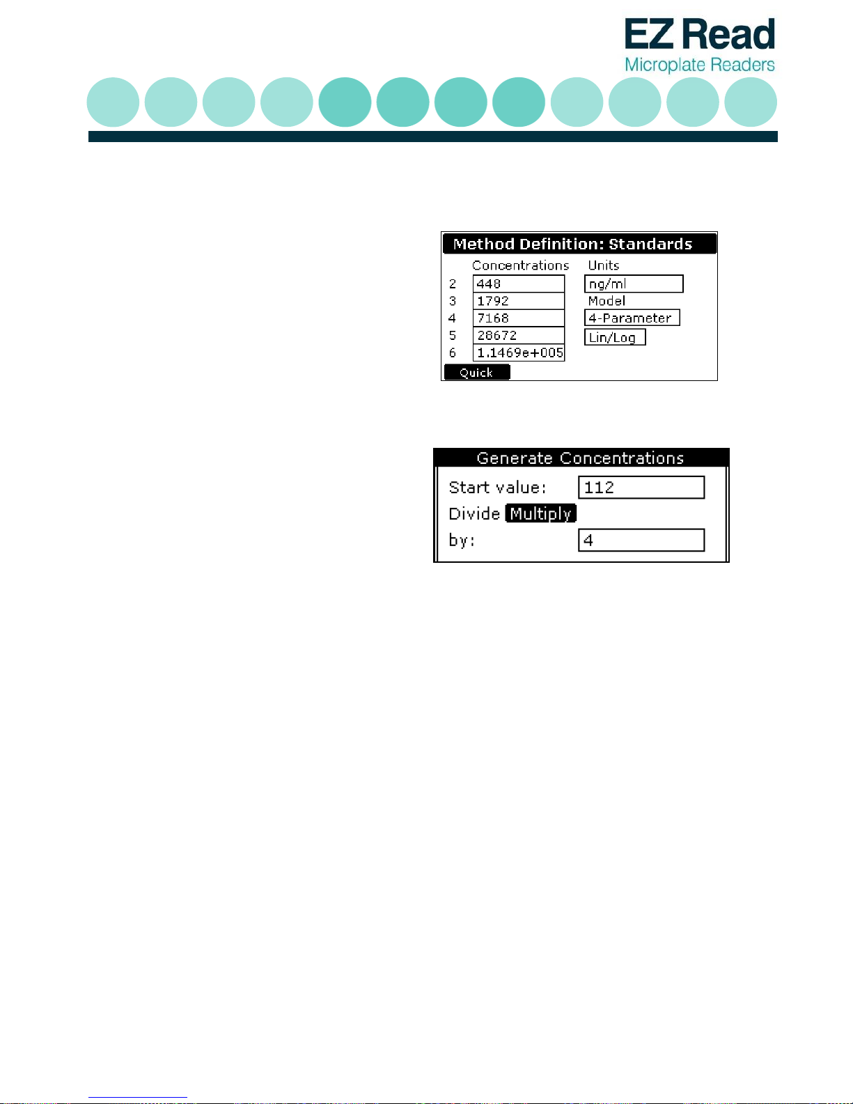
1. The concentrations for the standards
should be entered first. The screen offers
as many entry fields as standards have
been defined.
2. In case the standards are in linear serial
dilution, the Quick key (F1) offers a quick
way of entering the concentrations.
3. Units can be defined using the alphanumeric routine.
4. Select the analysis model for the standard curve. The options are Linear regression, Parabolic,
Cubic, Point to Point (linear interpolation), Spline and 4-parameter.
5. Select the y- and x-axis format required for presentation of the results; linear/linear, log/linear,
linear/log, log/log.
Page 27
27
6. Press enter to move to the next method definition box.
3.7.2.5 Method Definition: Kinetics
If kinetic measurements are to be defined, the Kinetics calculation definition window will appear after
the layout has been set up. The calculated results for these kinetics options are normally used as the
basis for quantitative, qualitative or combined sample evaluation.
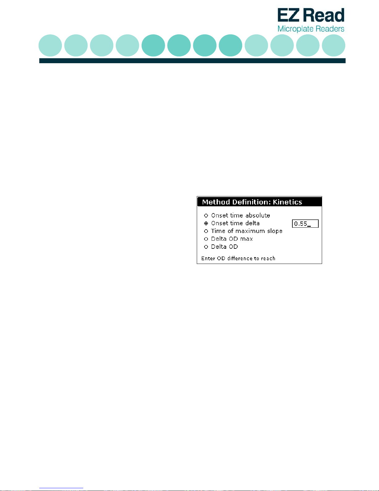
1. Five kinetic calculation options are
available:
1. Onset time absolute
This option calculates the time required to reach
the absorbance value specified in the input field,
for each well. A linear regression is used to
interpolate the time between the kinetic
measurement points.
2. Onset time delta
The option calculates the time required for the
Absorbance difference between that of the first
measurement and that specified in the input field
to be reached, for each well. A linear regression is
used to interpolate the time between the kinetic
measurement points.
Page 28
28
3. Time of maximum slope
This option calculates the time at which the
maximum slope is reached. A linear regression is
performed for every three consecutive readings
over the whole measurement time. The center
point in time of the regression with the steepest
slope is the time the maximum slope.
4. Delta OD max
This function calculates the absorbance change,
normalized to a minute; for the three readings at
the maximum slope.
5. Delta OD
The absorbance change, normalized to a minute,
over the whole measurement time is calculated.
NOTE: If none of these kinetic options is chosen, the raw absorbance data for each well at the
specified time intervals can be printed out.
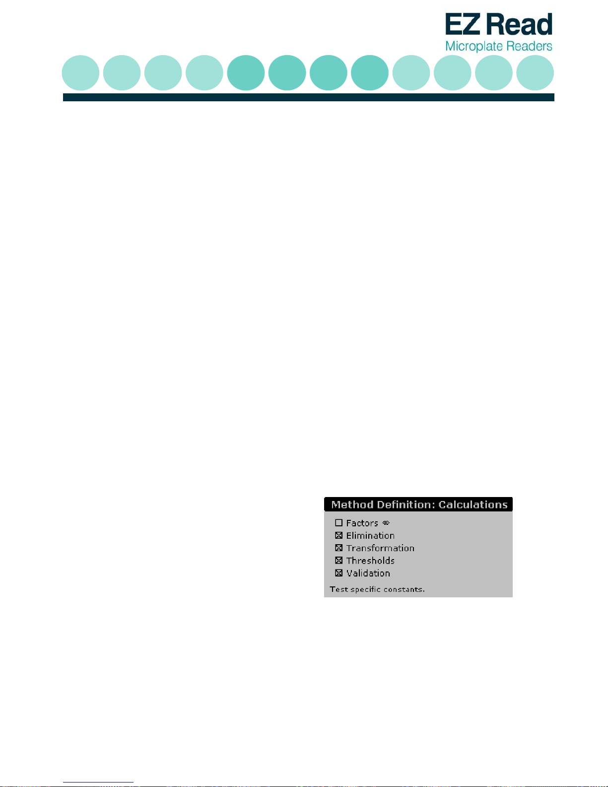
3.7.2.6 Method Definition: Calculations
1. If kinetics is not selected, the Calculation
window will appear after the layout has
been set up.
2. Use the left / right keys to select the option required, and up / down keys to move onto the
next.
Page 29

29
3. Press enter to move to the next method definition screen. Depending on the selected options
different screens will be shown.
NOTE: In case controls are used in replicates they must be referred as avg(xx), otherwise they are not
recognized in a formula (xx should be replaced by the name of the control).
3.7.2.7 Method Definition: Factors
1. Use this option to enter a constant specific to a particular test, for example to compensate for
batch variations if biological materials are being used as part of the assay kit. Thus if the
material is less biologically active than it should be, the manufacturer will specify the use of a
factor or factors to normalize results to what they should be.
2. These factors can be used in any further calculation step, e.g. in the transformation formulas.
3. Press enter to move to the next method definition screen.
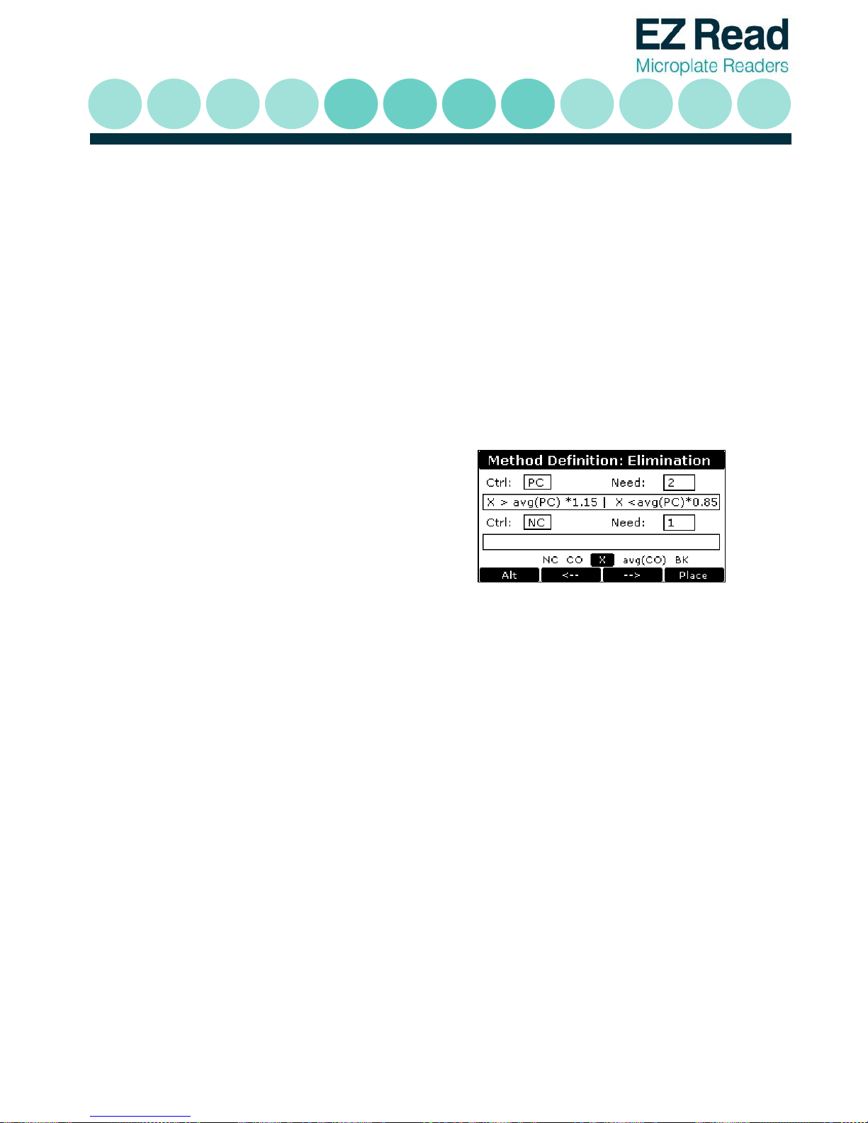
3.7.2.8 Method Definition: Elimination
This option allows users to define conditions for the automatic elimination of individual controls which
do not meet the set criteria. Two different controls can be evaluated.
1. The selection field Ctrl: shows the selected control types, the left / right cursor keys are used to
scroll through the available ones. Only control types which are defined in the layout are shown.
2. The field Need is used to enter the number of controls which should be left after the
elimination process. When this condition is not met, the test is declared invalid.
Page 30
30
3. The next entry field is used to enter the condition for the elimination. For example individual
positive controls should be eliminated which are deviating more than 15% from the mean
value. The condition is entered as following:
X > avg(PC) *1.15 | X < avg(PC) *0.85
X represents any single well of the positive control well, the ‘|’ stands for a logical or.
4. The formula can be read as: If as single
positive control is higher than 115 % of
the mean value of the positive control or if
a single positive control is lower than 85 %
of the mean value then eliminate the
respective single positive control.
5. When the cursor is in the entry field the function keys are active and users can select different
options. There are three groups of elements that can be selected by pressing the F1 (Alt) key:
Controls (single and average) and the factors.
Operates +, -, /, etc.
All available mathematical and logical functions.
6. Use F2 and F3 to select the desired element and F4 to place it.
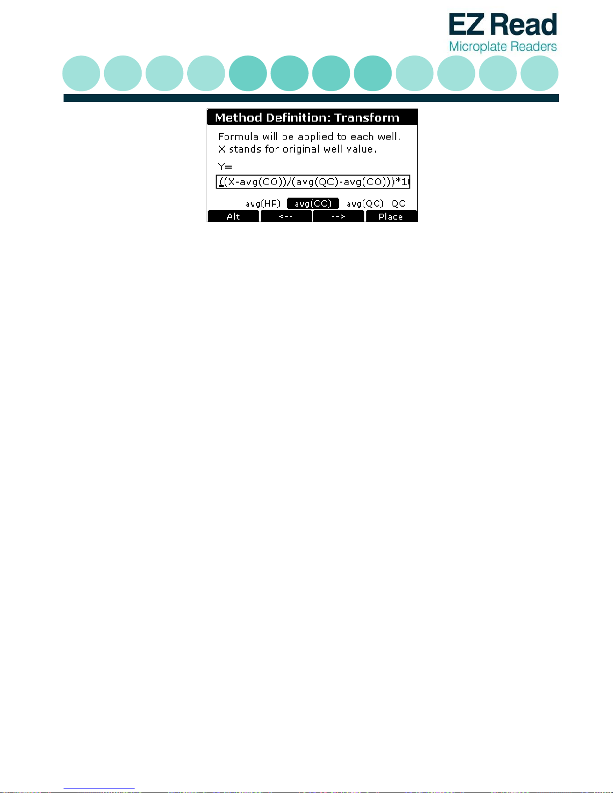
3.7.2.9 Method Definition: Transformation
Use this option to define a calculation equation to be applied to each well. All typical mathematical
functions are available (+ /- , sqr, abs, log, log10, x², etc.) and Pow (power of x).
Page 31
31
1. There are three groups of elements that can be selected by pressing the F1 (Alt) key:
Controls (single and average) and the factors.
Operates +, -, /, etc.
All available mathematical and logical functions.
2. Use F2 and F3 to select the desired element and F4 to place it.
NOTE: If a Blank (BK) is defined it will be automatically subtracted from the absorbencies of all other
wells.
3. Example: An index (in per cent), based on the absorbance of the CO control should be
calculated for each well (Absorbance of the CO control = 100 %).
The formula should be entered as follows: (X*100) / avg(CO)
4. Press enter to move to the next method definition screen.
Page 32

32
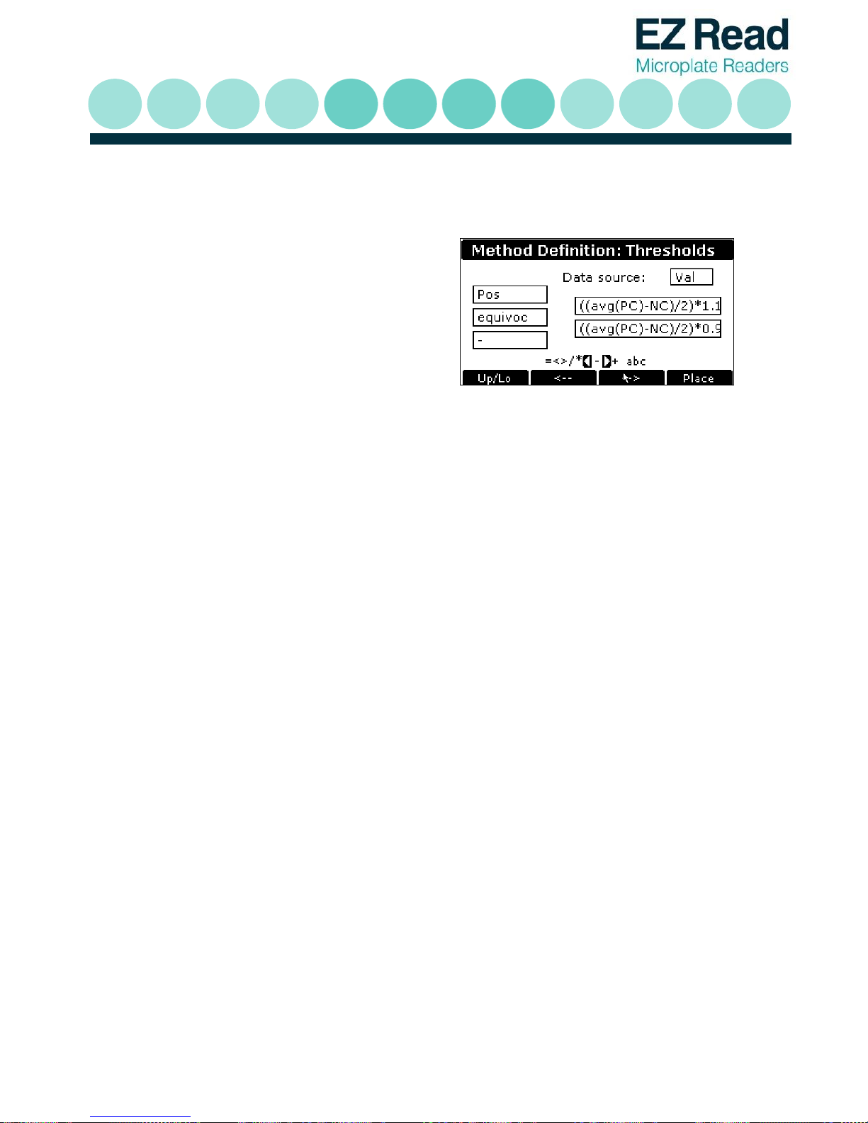
3.7.2.10 Method Definition: Thresholds (Cut-off)
Use this option to define the threshold limits for a qualitative result. Up to three different classes
(ranges) are possible. The label for the classes can be user defined. For n thresholds you have n+ 1
quantitative label.
Cut-off limits can be defined for the measured absorbance values (OD.), kinetic values, transformed
values or concentration values, depending on the test protocol.
1. To define the threshold(s) proceed as follows:
Select the data source first. The options are:
'Val' (absorbance or kinetic data),
'Trf' (transformed data)
'Conc' (concentration)
Next enter the label for the upper limit in the top left edit field. This can be a text like 'Positive'
or a symbol like '+'. Now enter the threshold condition for the upper limit. This can be a value
or an equation. After the condition for the upper limit has been entered, labels for other classes
and corresponding conditions can be entered.
2. The threshold limits work as follows:
Label 1 If X > A Label 1
Threshold A
Label 2 If X <=A and X >B Label 2
Threshold B
Label 3 If X <= B Label 3
(X ... Value of well)
Page 33
33
3. The example below shows the setup for a
typical ELISA assay. Here a sample is
considered to be positive if the
absorbance value is above (mean Positive
control - Negative control) / 2.
In addition it is specified that samples
that are +/- 10% of the cut-off are
considered as equivocal.
4. Press enter to move to the next method definition box.
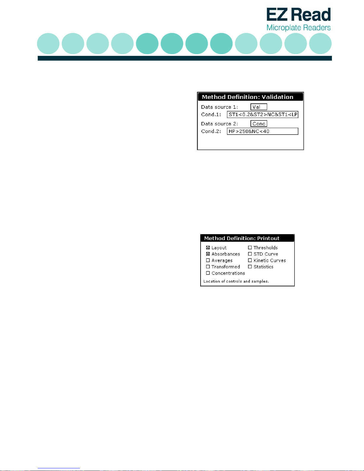
3.7.2.11 Method Definition: Validation
Use this option to apply parameters to ensure that the test is valid within the requirements stated by
the assay test protocol. If these conditions are not met, the result of the test is considered not valid.
This is indicated on the printout.
Validation criteria can be defined for the measured absorbance values or kinetic values (Val),
transformed values (Trf) as defined in Transformation or concentration values (Conc), depending on the
test protocol.
1. To define a validation condition chose the data source first. Then enter the first condition. At
the bottom of the screen you can see various options like avg(PC), Fct1, etc. Use the function
keys F2 and F3 to select the desired option and press F4 to place the selected option. ‘Alt’ (F1key) toggles between well types, mathematical operators and mathematical functions.
2. To connect 2 or more conditions of the same data source use the ‘&’ sign. If you use ‘&’
between two conditions BOTH must be fulfilled in order for the measurement to be valid.
Use >= for and <= for .
Page 34
34
3. For example for an ELISA assay the
following criteria must be fulfilled:
The absorbance of the Standard 1 must be <
0.2.
The absorbance of the Standard 2 must be
higher than that of the Negative Control.
The absorbance of the Standard 2 must be
lower than that of the Low Positive Control.
The High Positive Control must be > 250
IU/ml.
The Negative Control must be < 40 IU/ml.
4. Press enter to move to the next method definition box.
3.7.2.10 Method Definition: Printout
Use this option to select the content of the
printout. You can select one, several or all options.
Only options relevant to the assay that has been
defined / selected are displayed. The image below
shows all options that are possible (if kinetics has
been selected, the option for absorbances is
replaced by Kinetic values).
1. If replicates have been used, the average value can be printed out.
2. Press enter to move to the next method definition box.
3.7.2.10 Method Definition: Saving Method Definition
The complete method has now been defined and should be saved in the non-volatile memory. There
are three options how the new methods should be stored.
Page 35

35
1. The new method can be appended to the list of already existing methods by scrolling down
the list and pressing the Append (F4) key.
2. It is possible to store the new method at any position in the list by scrolling to the desired
position for the new method. Press now the Insert (F4) key, the new method will be
inserted before the current selected position.
3. In case an existing method should be replaced by the new one, scroll to the method to be
replaced and press the Replace (F3) key.
4. Enter the method name using the alphanumeric function and press enter. This new method
is then placed as the default method for the next measurement.
3.7.3 Running a Method
This can either be done immediately after defining a method (press 1) or by recalling an existing
method (press 2, select using and F4). The plate carrier will move out now, allowing loading the
microplate.
1. Each plate requires a unique ID. This ID is used to identify the plate on the printout and the
measured data for later recall.
2. In case an ID already used is entered, the screen will show a warning, asking if the previous
measured data with the same ID should be overwritten.
3. The maximum number of samples for the chosen method is displayed below the plate ID.
When less than the maximum number of samples should be processed, the number of
existing samples can be entered. This will avoid that empty well positions show unwanted
results.
4. Press the F3 key to select the post run option from three choices:
Printer
Use if a printer is connected (results are sent out via both the parallel and
serial data ports)
Page 36
36
Serial
Use if PC connected to send results through the serial port.
None
Use if neither printer nor PC are connected. Results are stored in the
memory and can be recalled later using the Recall Plate Data option. This
can speed up the measurement of a batch of plates significantly.
5. When the plate ID has been entered press the RUN or the ENTER key to start the
measurement. During reading the screen shows a status message. A soft-key labeled ‘STOP’
is the only key active during reading and subsequent printing. Up to 100 plate data results
can be stored in memory. After this is full the new results overwrite the previous results. To
avoid this, results can be downloaded to PC for archiving.
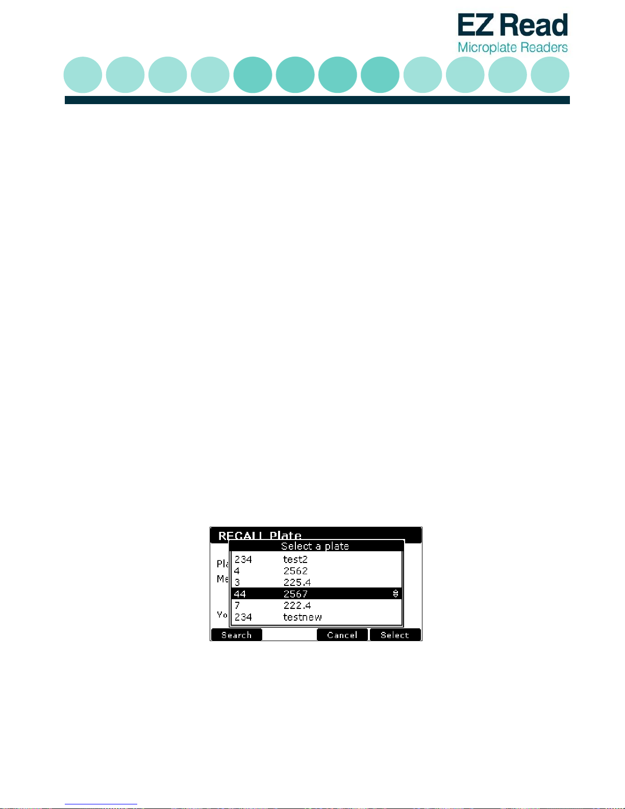
3.7.4 Recalling a plate
Previously run assays are stored using the unique plate ID. The Recall menu can be called from the main
menu by pressing key 3 and the ID.
1. The screen below shows a list of stored plates. The left column indicates the plate ID, the
center column shows the method used for the measurement.
A plate can be chosen using the up / down arrow keys or with the help of the search
function. The search function is especially useful in case of many stored plates.
Page 37
37
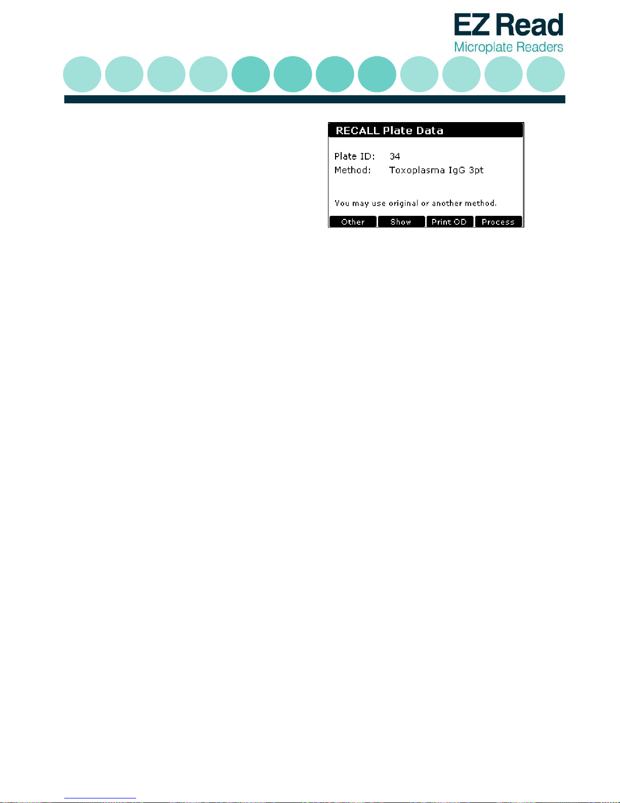
2. After a plate has been chosen press
either F4 or the Enter key to load the
data from the memory.
3. Further options include:
Other
Use a different method. Available methods are
displayed (see earlier).
Show
Show the plate data
Print OD
Print the OD values obtained for the plate. No
calculations are carried out
NOTE: It is the sole responsibility of the user to make sure that the chosen method gives useful
results. The program cannot determine if the selected method makes sense with the existing data.
4. When the measured OD values should be printed press the key F3 (Raw). No calculations
will be performed with this option.
5. To show the measured OD values on the screen of the reader press F2 (Show).
Page 38
38
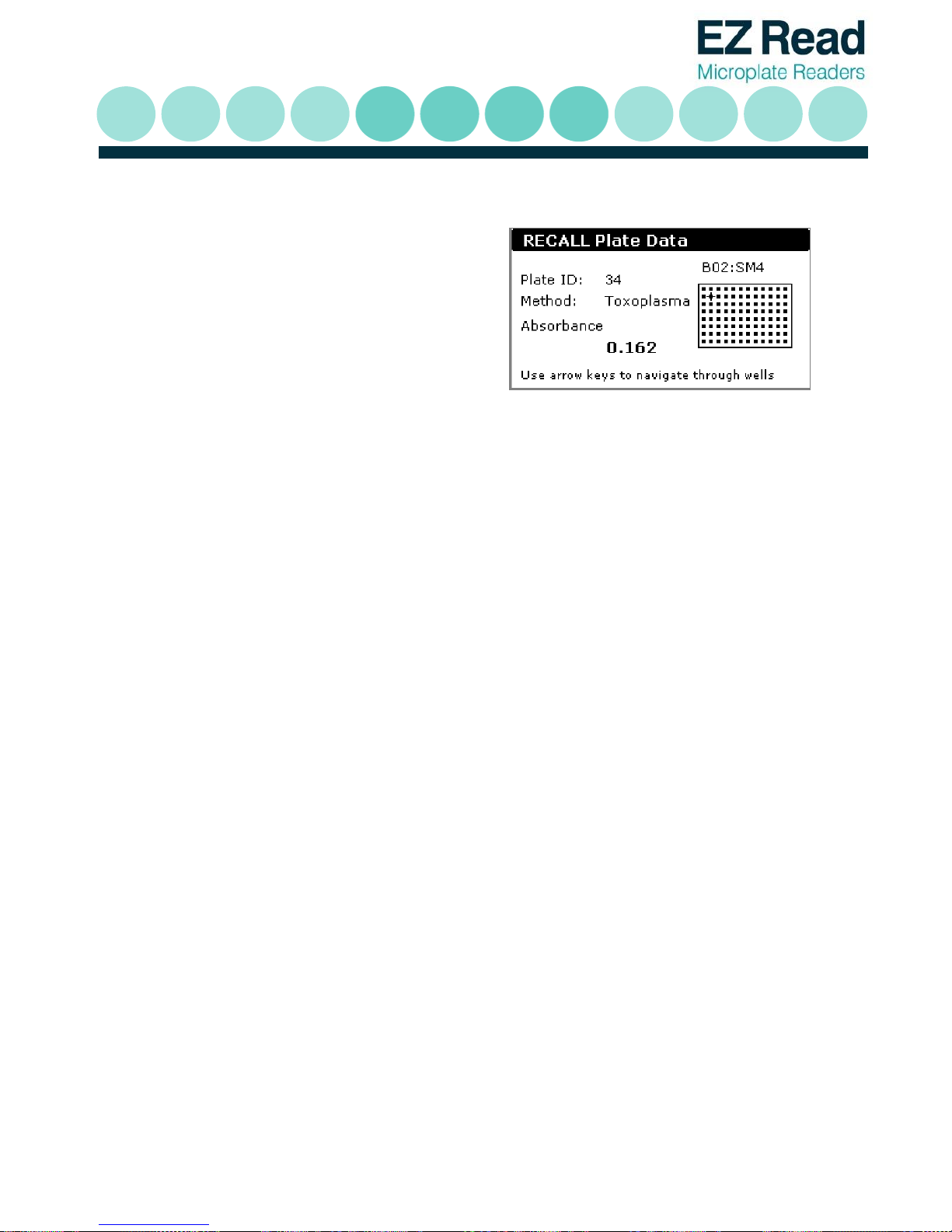
6. The new screen shows the plate ID,
the original method and the
absorbance (OD. value) of the
selected position.
On the right side of the screen there is
a representation of a microplate. You
can move across the plate with the
cursor keys to select a particular well.
At top of the plate representation the
actual well location and the well
designation is indicated.
3.7.5 Setup
3.7.5.1 Setup: Printer
Use this option to define which printer is connected to the plate reader. You can chose from a wide list
of printer models.
Many different printers can be used with generic type drivers. Consult the printer manual in case your
printer is not listed, to find out the nearest compatible type.
Use the up / down arrow keys to highlight the printer required and press enter to confirm your
selection. Depending on the printer type some options like paper size may be shown. Use the function
keys to select the required option and press the OK key to confirm the selection.
3.7.5.2 Setup: Filters
The Filter submenu serves to review the installed filters, inform the system about new or removed
filters and to perform a calibration. To remove a filter from the list enter 0 (zero) for the wavelength
and press F3 (Curr). To add a filter, enter the wavelength of the newly installed filter in the respective
edit field corresponding to the position on the filterwheel and press F3.
Any new installed filter must be calibrated to save the wavelength information.
It is strongly recommended that all filters be calibrated before the instrument is used the first time.
Page 39

39
For a technical description of the calibration process please refer to chapter 3.
3.7.5.3 Setup: Date/Time
Use this menu option to change the date and time with and the keypad. A choice of AM, PM or 24
hour clock is available.
3.7.5.4 Setup: Contrast
Use this option to change the contrast of the liquid crystal display using the F1 and F2 keys.
3.7.5.5 Setup: Language
Use to select the language that is used on the displays and printouts.
4. Technical Information
Please see Biochrom’s website: www.biochrom.co.uk for complete technical specifications.
5. General Features
5.1 Measurement modes
Single, dual and multi-wavelength and kinetics measurements with absorbance data output in
OD on display.
5.2 Integrated quality control
Post-sample filtering to eliminate ambient light.
Automatic calibration prior to each measurement.
Page 40

40
Plate centering system positions the well accurately and reproducibly under the optical
path only if it is a 96-well microplate that conforms to the ANSI SBS 1_2004 standards.
5.3 Scope of supply
Instrument
CD containing user’s manual and Galapagos Software.
USB PC cable
Dust cover
Power supply
Mains power cord
Please Note: Only use the power supply and mains power cord supplied with the instrument.
5.4 Liability
In its original condition the instrument meets all safety regulations for safe operation. If the
instrument is used in a manner not specified in this user’s manual, safety and performance
may be affected. Biochrom is not liable for damages or costs caused by unauthorized
alterations, repairs or modifications of the equipment .
Maintenance
6.1 Approved Parts
Except for the parts shown in the following list, only parts supplied by Biochrom or an
authorized Biochrom Distributor may be installed in or used with the EZ Read 800 Plus.
6.2 Cleaning and Disinfection
All parts of the reader that come into contact with potentially infectious material must be
treated as potentially infectious and should be periodically clean and disinfected. Only
authorized and trained personnel in a well-ventilated room while wearing disposable gloves,
protective glasses and clothing should perform the cleaning and disinfection procedures
The following materials are recommended for cleaning and disinfection of the reader:
Page 41

41
Lint-free tissues.
70% ethanol or a 0.5% bleach solution
6.3 Instrument cleaning
The following cleaning procedure should be regularly performed and after any spillages.
1. Disconnect the instrument from the power supply and the PC.
2. Carefully wipe off the entire reader with lint-free tissues that have been moistened in a
70% ethanol or a 0.5% bleach solution.
3. Put lint-free tissues that have been moistened in 70% ethanol or a 0.5% bleach solution
onto the plate transport mechanism and let it soak for ± 30 minutes.
4. When a bleach solution has been used, carefully wipe off the entire reader with lint-free
tissues that have been moistened in water.
5. Dry the reader by wiping it off with lint-free tissues.
6.4 Additional Maintenance Tips
Never spray liquids directly into the interior of the reader.
Do not use force when cleaning the reader.
Wipe up spills immediately.
Avoid buildup of dust on the instrument and wipe off visible dust.
Cover the instrument with the dust cover if not in use.
Warranty and Return to Base
7.1 Warranty Terms and Conditions
This warranty refers to the obligations of Biochrom and can only be amended upon the
written consent of Biochrom Ltd.
Page 42

42
A warranty period of 24 months shall be granted to the original buyer of the Biochrom EZ
Read 800 Plus Microplate Reader.
The warranty shall lose effect if any of the below conditions occur:
Biochrom EZ Read 800 Plus Microplate Reader is not used in the defined scope of
application.
Biochrom EZ Read 800 Plus Microplate Reader has obviously been damaged by
external influences which are not in accordance with the provisions for the nominal
range of use.
Biochrom EZ Read 800 Plus Microplate Reader has been modified or parts exchanged
by a person other than Biochrom personnel or an authorized servicing agent.
The warranty seals on the housing of the instrument are broken.
The parts and subassemblies have been installed, which are not original from
Biochrom.
Biochrom EZ Read 800 Plus Microplate Reader serial number is no longer legible,
because it has been removed or altered.
Biochrom EZ Read 800 Plus Microplate Reader has not been installed in accordance
with supplied instructions.
Biochrom EZ Read 800 Plus Microplate Reader has been damaged during return
transport due to wrong packing (e.g. not in original packing material).
Biochrom EZ Read 800 Plus Microplate Reader was damaged due to improper
operation and outside of the use described in this manual.
If an instrument is returned, Biochrom will repair or replace any defects, which have resulted
from faulty material or during production as it sees fit. No costs shall arise for the client
(except the cost of shipping the instrument).
All components found in the original equipment, or an adequate and full compatible
alternative shall be available for a period of 7 years after manufacture. Instrument parts are
available for 7 years after the instrument is no longer manufactured.
7.2 Returns Terms and Conditions
In the event that you need to return your instrument to us for repair or to use our in house
recalibration service, the following instructions which should be carried out in full:
Page 43

43
If your instrument is in warranty contact technical support: [email protected]
If your instrument is out the warranty period, you must provide a purchase order number for
the repair on your returns form.
If you need to know that cost of repair/recalibration, please send an e-mail to
[email protected].
All policies and procedures, forms and labels can be found in returns in the support section of
the Biochrom website: www.biochrom.co.uk.
7.3 Returns Procedure
1. On the Biochrom website, complete the returns authorisation form
(http://www.biochrom.co.uk/content/1/65/returns.html) and send this to Biochrom to
obtain a returns authorisation number. This number needs to be written clearly on the
outside of your returns package.
2. Please do not send your package to us until you have received a returns authorisation
number.
3. Download a decontamination certificate from and include this certificate with your
package. Please put a copy on the outside and inside of your package.
Please Note: Instruments which are returned without a decontamination certificate
will not be processed. This would result in significant delays and additional
administration charges for your repair.
IMPORTANT: For returns outside the EU, please complete your commercial invoices,
making sure that you indicate the true commercial value of the return. Please also
state the following on your invoice:
“Temporary Import – Item Returning to Supplier for Repair”
4. Send the package to Biochrom using the address label (found on the Biochrom website:
(http://www.biochrom.co.uk/content/1/65/returns.html) and your own carrier. The
goods being returned must be securely packaged and in a manner to prevent transit
damage.
5. Below is a checklist to make sure that you have completed all steps:
Purchase order number for repair
Return number on outside of package
Decontamination certificate included on outside and inside of package
Page 44

44
Customs declaration of true value
Customs declaration: Temporary Import etc.
Have read and understood the returns terms and conditions
(http://www.biochrom.co.uk/returns_terms.html)
For all returns enquires please contact [email protected] or
+44(0)1223 427861
Page 45
45
8. Ordering Information and Accessories
Table 1 Ordering Information
ORDERING INFORMATION
80-4002-02
Biochrom EZ Read 800 Plus ELISA
80-4002-03
Biochrom EZ Read 800 Plus Research
SS01751
EZ Read Microplate Reader Check Plate
See www.biochrom.co.uk for a list of filters that are available for purchase.
9. Contact Information
Table 2 Contact Information
Department
Email contact
Telephone contact
Sales
+44 (0) 1223 423723
Technical Support
+44 (0) 1223 427890
Orders
+44 (0) 1223 427861
+44 (0) 1223 420 164 (Fax)
Returns
+44 (0) 1223 427861
Human Resources
Accounts
+44 (0) 1223 427816
Page 46

46
Appendix:
10.1 Helpful Hints for Successful Microplate Assays
Always insert the plate with well A1 on the upper left position.
Keep plates clean: measurements in microplates are made through the surface of
the plate and thus the surface should be as free as possible of debris, scratches and
smudges. Wipe the plate clean with a lint-free tissue if necessary.
Measurements may be affected by uneven or heterogeneous well contents. Visually
inspect the plate for foaming, uneven meniscuses, bubbles or particles in the well, all
of which can interfere with absorption. Centrifuge the plate if necessary to obtain a
homogeneous level in the wells.
Use a reference measurement for reducing measurement error caused by
interference from the plate material or contamination. (Use a reference wavelength
at which your molecule of interest does not absorb. Many assays recommend a
reference measurement at 620 nm).
When using plate frames for stripwells or single wells (breakable strips) check that all
strips and wells are pushed down completely and are level with the frame.
Keep the bottom of the plate dry. If liquid has contaminated the well bottoms or if
condensation is present, dry the surface with a lint-free tissue.
Use high quality optically clear 96-well microplates (such as virgin polystyrene) with
standard ANSI SBS footprint for the best results.
10.2 Troubleshooting and Frequently Asked Questions
Biochrom’s technical support team is available to answer all of your questions regarding your
EZ Read 800 Plus microplate reader:
Please also see the support section of our website which is frequently updated with technical
and applications support information.
Below is a list of frequently asked questions and answers:
Page 47

47
1. What is the indication range of the EZ Read 800 Plus and how does this specification
differ from the linear range?
The Biochrom EZ Read 800 Plus has an indication range of 0.000-3.300 OD and a linear
range of 0.100-2.500 OD. We recommend that the broader indication range should be
used only for relative determinations but not for determining the quantity of the
absorbing material. Only measurements made within the linear range should be used for
quantitative calculations.
2. If a measurement is made by the Biochrom EZ Read 800 Plus that exceeds the maximum
indication range, how is that measurement represented?
If a well measurement at a particular wavelength exceeds the maximum indication range,
then the well will be represented with ‘’O/R’’.
3. When using Galapagos software to control the Biochrom EZ Read 800 Plus, can specific
wells be designated as blanks and can those values be automatically subtracted from the
remaining wells?
The Biochrom EZ Read 800 Plus comes with standard software, Galapagos Software,
which does allows the user to define specific wells. Specific wells can be allocated to
certain controls (such as positive or negative controls). Users can input details of the
controls such as the name and type of control. Users can use threshold calculations to
subtract readings from other wells.
4. Which Microsoft Windows operating systems are Galapagos compatible with?
Galapagos is compatible with Windows XP with SP3 and higher versions.
5. Why do I get different readings from the same sample in different wells in the
microplate?
Check correct sample volume has been dispensed. This is important as pathlength (which
is used to calculate sample concentration using Beer’s Law) is not standardised and is
dependent on sample volume. Therefore the volume must be equal throughout the plate.
The quality of the microplate is paramount to the quality of the measurements because a
microplate reader sends light through a sample vertically. Use high quality, optically clear
microplate for best results.
In addition, it is important to use a reference wavelength when measuring a microplate.
Microplates may have smudges, scratches, lids and other forms of optical interference
which may obstruct the light beam. A reference wavelength allows for a well by well
control of imperfections in the plate.
When choosing a reference wavelength, use a wavelength at which the sample of interest
Page 48

48
does not absorb. 620nm is a frequently used reference wavelength in many absorbance
applications in the visible range. Check the product data sheet for recommended
reference wavelength for your specific assay.
6. How can I connect the instrument to Galapagos?
Refer to section 3.2.
Page 49

49
Declaration of Conformity for Biochrom Manufactured Products
This is to certify that the following Biochrom manufactured products:-
EZ Read 800 ELISA Plus (80-4002-02) and EZ Read 800 Research Plus (80-4002-03)
Conform to the requirements of the following Directives:-
2006/95/EC Low voltage directive (LVD)
2004/108/EC Electromagnetic Compatibility (EMC) directive
2012/19/EU Waste Electrical and Electronic Equipment directive recast (WEEE Recast)
2011/65/EU Restriction on the use of certain hazardous substances (ROHS) directive
2006/42/EC Machinery directive
98/79/EC In Vitro medical devices directive (Annex I & III)
Standards, to which conformity is declared, are as follows:-
EN61010-1:2010 Safety requirements for electrical equipment for measurement, control and
laboratory use. General requirements
EN61010-2-101:2002 Safety requirements for electrical equipment for measurement, control and
laboratory use. Particular requirements for in vitro diagnostic (IVD) medical
equipment
EN61326-1:2006 Electrical equipment for measurement, control and laboratory use -EMC
Requirements*
EN ISO 12100:2010 Safety of machinery-General principles for design, risk assessment and risk reduction
*This equipment has been tested and found to comply with the limits for a CLASS A digital device, pursuant to
part 15 of the FCC Rules.
For further information, including unpacking, positioning and installation of the products please refer to the
user manual.
Signed: Dated: 07th May 2013
Sam Luke
Group Managing Director, Biochrom Ltd
 Loading...