

Page 1
EZPull RXP-02 Sporting clays Receiver Setup Manual
Connecting the Receiver to the Trap
The RXP02 is a remote switching device designed for use with
12VDC Sporting Clays trap machines.
WARNING: DO NOT CONNECT THE RECEIVER TO THE
TRAP MACHINE BEFORE GOING THROUGH THE
FOLLOWING PROCEDURE!
1. Determine if your trap uses “Negative” or “Positive” release:
1.1. If applying the “Switch” line to Ground (Battery -),
releases a target, it is a “Negative” release. If applying
the “Switch” line to the +12V releases a target, it is a
“Positive” release.
1.2. You can also measure the voltage on the “Switch” line in
reference to Ground (BAT-). If the voltage on this line is
approximately the battery voltage, it is a “Negative”
release trap.
WARNING: Do not exceed the maximum ratings!
* Maximum supply voltage 15VDC
* Maximum Trap switch current < 2Amp
* Maximum DC Trap switch < 30VDC
* Maximum AC Trap switch < 250VAC
2. Wiring the RXP02 4 wire cable - Connect the cable to a
plug suitable for your trap machine according to table below:
Wire
Color
RED +12VDC
BLACK GROUND (-)
BLUE Trap Switch N/O (Trigger)
YELLOW
Connect to
Trap Switch COM
For Positive release connect together with RED
For Negative release connect together with BLACK
Mounting the Receiver:
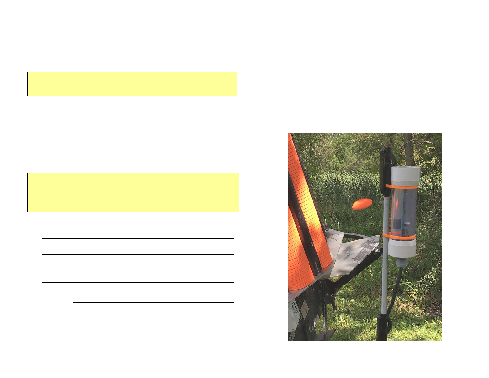
1. The receiver must be mounted vertically with the cable going
towards the ground.
2. For optimal performance, the receiver should be mounted a
few feet above the ground and a few feet away from the
Trap, preferably with a “line of sight” to the transmitter.
3. The SunGuard Step-In Post 3⁄8" 4 ft from Kencove
http://www.kencove.com/fence/Fib
SSG.php is a low cost and effective mounting solution. Use
p Ties to attach the receiver.
Zi
erglass+Posts_detail_F38
3. You can now connect the RXP02 receiver to the trap machine.
A Blue LED should glow indicating the receiver is ON.
Page 2

EZPull RXP-02 Sporting clays Receiver Setup Manual
Receiver LED Indicators
The receiver is equipped with Blue, Red and Yellow LED light
indicators.
1. The Blue LED is normally on, but when the receiver senses
radio traffic, the Blue LED goes off causing the LED to appear
as if it is flashing. This is useful for troubleshooting.
2. The Red LED is normally off and indicates the following:
2.1. When a Target command is received, the Red LED turns
on momentarily.
2.2. After each target release, the receiver checks the
battery condition. When the receiver detects a low
battery (LED ACID 12V battery), the Red LED flashes a
few times.
2.3. When in Pairing mode (see below), the Red LED glows
steady.
3. The Yellow LED is normally off It is used for timing setup
indications.
Pairing the Receiver with the Transmitter
Each shooting station requires a transmitter and receiver(s) on
the same unique address code.
To set the address on the transmitter, see the setup manual for
your specific EZPull model.
The RXP02 receiver is “Paired” with the EZPull on the desired
Trap number by simply pressing the specific Trap release key on
the transmitter.
1. Ensure the receiver is powered up. A Blue LED should glow
steady. A flashing Blue indicates EZPull systems are being
used by neighboring shooting stations.
2. To avoid mismatch with neighboring shooting stations,
ensure EZPull systems on other fields/stations are not being
used during this procedure.
3. Locate the magnetic Pairing switch on the receiver. It looks
like a red bar on the side of the circuit board across from the
LED indicators.
4. Hold a small magnet directly on top of the Pairing switch.
Blue and Red LEDs will start alternating. Keep holding the
magnet until only the Red LED glows steady and immediately
remove the magnet. The receiver is now waiting for a “call”
from a transmitter.
Notice: If you keep holding the magnet close to the pairing
switch after the Red LED goes steady, the system will enter
delay setup mode (see below).
5. Press the respective target key on the EZPull transmitter. If
Paring is successful, the lights will flash rapidly and the
receiver will revert to normal operating mode.
6. Press the target key on the EZPull transmitter again to verify
pairing. The Red target LED should glow momentarily.
7. Troubleshooting Pairing:
7.1. Blue and Yellow LEDs alternating – you held the magnet
too long and entered the timing setup mode. Remove
the magnet and then place it above the Pairing switch to
abort.
7.2. If the Red LED remains steady, check that your
transmitter is working, or try with another transmitter.
7.3. If the Red LED goes off without flashing rapidly, the
pairing failed, try again.
8. To abort Pairing mode, place the magnet above the Pairing
switch and remove it at once, the Red LED will turn off and
the Blue LED will turn on.
Page 3

EZPull RXP-02 Sporting clays Receiver Setup Manual
Using the Transmitter to setup timing functions:
The RXP02 can be set for several timing functions such as
delayed release, increased latch duration and reload delay.
1. To enter the timing setup mode:
1.1. With the receiver ON, hold the magnet directly on top of
the Pairing switch. Blue and Red LEDs will start
alternating. Keep holding the magnet until Blue and
Yellow LEDs start alternating. Remove the magnet.
1.2. The receiver is now waiting for a “setup command” from
the transmitter. While waiting for a command, the LEDs
display the current timing settings in a repetitive loop.
1.3. To abort timing setup mode, place the magnet above
the Pairing switch and remove it at once, the receiver will
return to normal operation.
2. Setting the Release Delay: the RXP02 can be set for a
delayed release. This feature replaces expensive timers and
is useful in setting precision timing on following pairs.
2.1. The yellow LED indicates the release delay:
2.1.1. No Delay - Yellow blinks once
2.1.2. Delay 1 Sec- Yellow blinks twice
2.1.3. Delay 2 Sec- Yellow blinks three times
2.1.4. Delay 3 Sec- Yellow blinks four times
2.2. The [1-A] button on the transmitter adjusts the release
delay. Click the [1-A] button and observe the Yellow LED
blinking. The adjustment is cyclical. See above: 2.1.1. -
2.1.2. - 2.1.3. - 2.1.4. - 2.1.1. …
3. Setting the Latch and Reload timing:
Latch time: some traps may require a longer period to
release a target. The RXP02 can be set to close the release
switch for a longer period of time.
Reload time: this feature is for use with EZPull controllers
that can throw a following pair from the same trap (Rafael).
3.1. The Red LED indicates a longer reload period and the
Blue LED indicates longer latch time:
3.1.1. Latch 0.4 Sec, Reload 2 Sec. – No lights
3.1.2. Latch 0.6 Sec, Reload 2 Sec. – Blue LED
3.1.3. Latch 0.4 Sec, Reload 4 Sec. – Red LED
3.1.4. Latch 0.6 Sec, Reload 4 Sec. – Blue and Red LEDs.
3.2. The [2-B] button on the transmitter adjusts the Latch
and Reload timing. Click the [2-B] button and observe
the LEDs. The adjustment is cyclical. See above: 3.1.1. -
3.1.2. - 3.1.3. - 3.1.4. - 3.1.1. …
4. Save and Exit:
to save and abort the setup mode.
4.1. From TX-C2/3 or TX-VR2, press the [T] key.
4.2. From TX-4 or MTX-8, press [TP], then select [1-A] and
[2-B] and then press [TP] again.
Troubleshooting:
Always use comparative approach to troubleshooting. If both
receivers don’t work, the problem is most likely with the
transmitter. If a transmitter works with one receiver but not with
the other, check the receiver, etc.
Receiver does not throw targets - Stand close to receiver. While
observing the LED indicators, press the respective key on the
transmitter:
1. No lights – Check the receiver has power. Check that
transmitter indicators are on when you press the key.
2. Red light on receiver turns on and Blue light turns off
momentarily– the target command was received – check
wiring to trap.
3. Blue light turns off momentarily but no Red light – check
pairing with the transmitter. Follow the pairing procedure
described above.
Send a True pair A + B from the transmitter
 Loading...