

EZ-Net NEXT-3000SFP-POE, NEXT-300FSCSWA-POE, NEXT-POE514FDT-SCM, NEXT-POE515FDT-SCS, NEXT-POE516FDT-A User Manual
...
Optical Media Converter
User Manual
V1.1
Please read before using the device
www.ez-net.co.kr

Industrial POE Media Converter / Industrial POE Switch
Page 2 of 2
www.ez-net.co.kr
1. 제품소개
.산업용 광미디어 컨버터 5 종의 제품과 산업용 스위치 6 종의 제품으로
구성된 공용사용자 설명서입니다.
NEXT-300FSCM-POE / NEXT-300FSCS-POE /NEXT-300FSCSWA-POE/
NEXT-300FSCSWB-POE / NEXT-3000SFP-POE 산업용광미디어 컨버터
시리즈모델과 NEXT-POE514FDT-SCM / NEXT-POE515FDT-SCS /
NEXT-POE516FDT-A / NEXT-POE516FDT-B / NEXT-POE524FDT /
NEXT-POE1524GDT 산업용 POE 스위치는 열악한 환경에서도 안정적으로
작동할 수 있는 견고한 Industrial Level Four EMC 기준으로 설계되었습니다.
.Auto-Negotiation 및 LED 램프를 지원하여 네트워크를 제공하는 이상적인
솔루션입니다.
.이 장치는 네트워크 안정성을 보장하기 위하여 전원이중화 시스템
(12~56VDC)를 지원합니다. DIN 레일 장착 및 벽면장착의 두 가지 설치방식
에 대응하여 편리한 현장설치가 가능합니다.
.POE IP 카메라 및 POE 무선 AP 와 같은 모든 종류의 IEEE802.3at
PD(Powered Device)를 지원하며 포트당 최대 30W 의 전력을 지원합니다.
(48V DC 이상의 전원공급 시 POE 기능이 동작합니다.)
2. Packing list
Industrial media converter/Switch 1piece
Warranty card 1piece
User manual 1copy
DIN-rail or wall mounting kit 1piece
Note : "The product components are subject to change without notice.
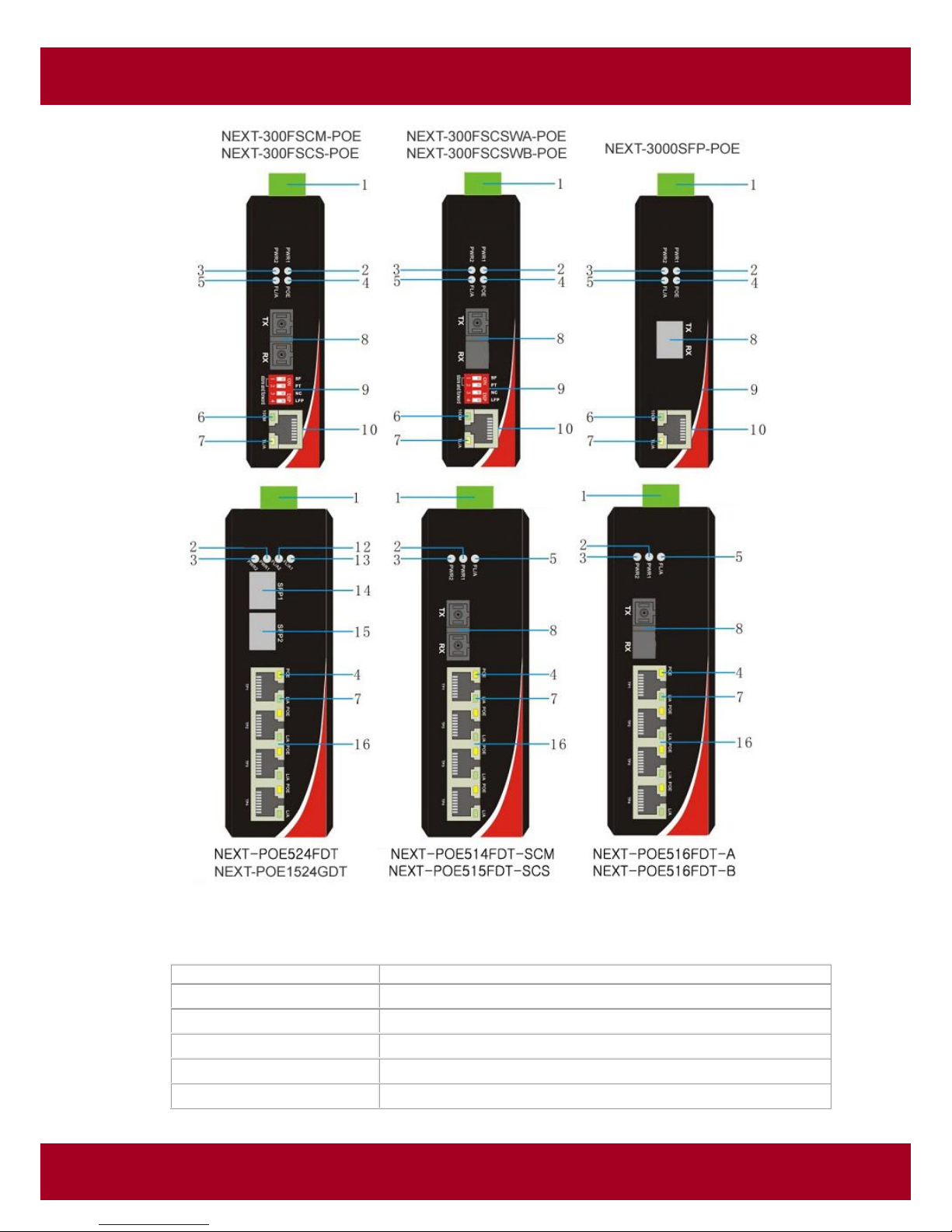
3. The panels and LED indicators
Industrial POE Media Converter / Industrial POE Switch
Page 3 of 3
www.ez-net.co.kr
<Industrial Optical POE Media Converter>
Model No.
Description
NEXT-300FSCM-POE
10/100M MMF,1310nm,SC,2km, with POE
NEXT-300FSCS-POE
10/100M SMF,1310nm,SC,20km, with POE
NEXT-300FSCSWA-POE
10/100M Bi-di TX1310/RX1550nm,SC,20km, with POE
NEXT-300FSCSWB-POE
10/100M Bi-di TX1550/RX1310nm,SC,20km, with POE
NEXT-3000SFP-POE
10/100/1000M SFP with 1TP POE
Industrial POE Media Converter / Industrial POE Switch
Page 4 of 4
www.ez-net.co.kr
<Industrial POE Switch>
Mark
Name
Function
1
Terminal block
Power supply and Grounding port
2
PWR1
“On”: Power 1 is on and normal
3
PWR2
“On”: Power 2 is on and normal
4
POE
“On”: Power over POE port is on and normal
5
FL/A
“On”: Fiber link is in correct connection.
“Blink”: Signal packet goes through Fx end
6
100M
“On”: 100Mbps
7
TL/A
“On”: Electric link is in correct connection.
“Blink”: Signal packet goes through Tx end
8
Optical port
Fiber optic connecting port.
Connector type: SC, GBIC, Bi-di
9
DIP Switch
To control the LFP function
10
RJ45 port
Copper cable connector
11
100M
“On”: 100Mbps
12
FL/A2
“On”: SFP2 Fiber link is in correct connection.
“Blink”: Signal packet goes through SFP2 Fx end
13
FL/A1
“On”: SFP1 Fiber link is in correct connection.
“Blink”: Signal packet goes through SFP1 Fx end
14
SFP1
SFP mould port 1
15
SFP2
SFP mould port 2
16
1×4 RJ45
Copper cable connector
17
DIN kit
DIN-rail mounting kit
18
Ear kit
Wall mounting kit
Model No.
Description
NEXT-POE514FDT-SCM
Industrial 10/100M Dual SC + 4TP POE Fiber Switch(1310nm/2Km Multi-mode)
NEXT-POE515FDT-SCS
Industrial 10/100M Dual SC + 4TP POE Fiber Switch(1310nm/20Km Single-mode)
NEXT-POE516FDT-A
Industrial 10/100M SC + 4TP POE Fiber Switch( Bi-di TX:1310nm RX:1550nm/20km
NEXT-POE516FDT-B
Industrial 10/100M SC + 4TP POE Fiber Switch( Bi-di TX:1550nm RX:1310nm/20km
NEXT-POE524FDT
Industrial 10/100M 2SFP + 4TP POE Fiber Switch
NEXT-POE1524GDT
Industrial 10/100/1000M 2SFP + 4TP POE Fiber Switch

Industrial POE Media Converter / Industrial POE Switch
Page 5 of 5
www.ez-net.co.kr
4. Installation
4.1 DIN-rail installation
The DIN installation is based on the Pic 1 and Pic 2. Unload is based on
the Pic 3, then Pic2 and Pic 1.
Industrial POE Media Converter / Industrial POE Switch
Page 6 of 6
www.ez-net.co.kr
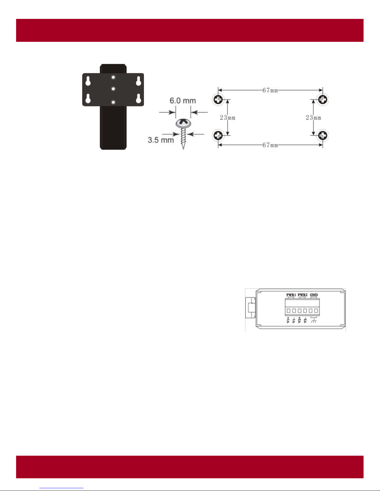
4.2 Wall-mounted installation
Pic 4 Pic 5 Pic 6
Fix hanging ears in the switch, as shown in figure 4;
Select 4 suitable screws (diameter of screw head should be less than 6
mm , diameter of screw should be less than3.5 mm diameter, as shown in Pic
5) and fix the device on the wall as Pic 6, don’t completely tighten the screws,
keep some space about 2mm.
Install hanging ear of switch alignment inside the four screws, then press
the switch down, ensure the hanging ear has been fix properly, and turn the
screw.
4.3 Wall-mounted installation
Input terminal of the switch for 6PIN plug type
terminals, V1+ and V1- is for power supply 1 (PWR1), V2
+ and V2- is for power supply 2 (PWR2) and GND for
earthing terminal, as shown in Pic 7.
Power 1 and power 2 input voltage range is 12VDC ~
56VDC,V1+,and V2+ are positive, V1- and V2- are
negative, and the equipment supports anti reverse
function;
Two sets of power can be simultaneously accessed.
So if One of the power failure, the switch is still able to
work;
Pic 7

Industrial POE Media Converter / Industrial POE Switch
Page 7 of 7
www.ez-net.co.kr
4.4 Copper cable connection
MDI
MDI-X
4.5 Fiber cable connection

Industrial POE Media Converter / Industrial POE Switch
Page 8 of 8
www.ez-net.co.kr
4.6 DIP switch
Switch
Status
Function
1:
On
Pass through mode
Off
Switch mode
2
On
Modified cut through mode
Off
Store-and-forward mode
3
On
No available
Off
4 On
Enable LFP function(default)
Off
Disable LFP function
5. Technical parameters
1. Power supply
Input voltage: 12V~56V (redundant dual power)
PSE Power: 0~30W
POE Pin: 1/2+,3/6-
2. Copper Port
Connector: RJ-45 connector
Data Rate: 10/100Mbps Auto
Twisted Pair cable: Cat5 UTP cable
Transmission distance: 100 meter
3. Fiber Port
Connector: SC, SFP
Data Rate: 155Mbps,1.25Gbps
Fiber Type: SM 9/125μm,MM 50/125μm、62.5/125μm
Transmission distance: 2km ~ 20km
4. Environment
Storage temperature: -40~95℃
Operating temperature: -40~85℃
Relative humidity: 5%-90%
5. Mechanism
Enclosure: IP 40, Black, Metal shell
Mounting: DIN-rail, Wall

Industrial POE Media Converter / Industrial POE Switch
Page 9 of 9
www.ez-net.co.kr
6. Standards
UL508
EMI FCC Part 15,CISPR(EN55022)
EMS en61000-4-2(ESD)Level 3
EN61000-4-3(RS)Level 3
EN61000-4-4(EFT)Level 3
EN61000-4-5(Surge)Level 3
EN61000-4-6(CS)Level 3
EN61000-4-8
EN61000-4-11
IEC60068-2-27
IEC60068-2-32
IEC60068-2-6
7. Warning
1. This product is suitable for indoor application.
2. Place the dust cover on the fiber interface when not in use.
3. It is dangerous to stare at the fiber transmitter with the naked eye.
4. Optical fiber transceivers must be used in pair.
5. Single optical fiber transceiver must be used in pair(A,B)
A: TX1310/RX1550nm B: TX1550/RX1310nm.
8. Trouble shooting
1. Device is not connecting. Please check that the corresponding network
device is using the same transfer rate as the media converter (10Mbps,
100Mbps or 1000Mbps).
2. If power loss is excessive in the fiber, please check and clean the fiber patch
cord connectors.
9. Responsibility Note
(1) The user should cover the damage during transport to equipment resend
for maintained at the user’s own expense
(2) Please contact your authorized reseller immediately, if there is any damage
to the equipment during transport
(3) If you want to prepare power supply by yourself, please make sure the
power supply you select meet the requirement given by this manual. We
will not cover the damage caused by your using unqualified power supply.
(4) Do please follow this manual when using the power supply.

Industrial POE Media Converter / Industrial POE Switch
Page 10 of 10
www.ez-net.co.kr
(5) All rights reserved. No part of this manual can be reproduced, or
transmitted in any form or by any means, without authorization form us.
(6) We will not cover the damage to the equipment or any person caused by
your changing the equipment or this manual in any form without
authorization from us.
(7) We will change the equipment for new ones if it can not work normally
because of the quality itself within the warranty time. We will keep the old
ones.
(8) The packages of the equipment meet the requests of environmental
protection, should be recycled.
Attention: If there are any printing mistakes in this manual, the right to explain
is reserved. And the pictures of equipment appearance in this manual are just
for user’s information, the final equipment appearance depends on reality
products, if there are any improvements on technology, we will be sorry for
won’t inform you again.
10. Dimension
(Industrial POE Switch) (Industrial POE Media Converter)

Industrial POE Media Converter / Industrial POE Switch
Page 11 of 11
www.ez-net.co.kr
11. Specification(Industrial POE Media Converter)
Standards
IEEE802.3 10BaseT; IEEE802.3u 100BaseT(X)
IEEE802.3x Flow control; IEEE802.1d Spanning Tree,
IEEE802.1Q VLANs; IEEE 802.3af/at POE
Performance
Processing Type : Store and Forward, Cut-through
MAC Table Size: 1Kbit
Buffer Space: 288Kbit
Time Delay: <150μs
Copper Port
Data Rate: 10/100M
Connector: RJ45
Distance: 100m
Fiber Port
Data Rate: 155M
Connector: SC as default
Distance: MMF=2km,SMF =20km,
Dip-switch
Dip1 ON + Dip2 ON = Modified Cut-through Mode
Dip1 ON + Dip2 Off = Converter Mode
Dip1 Off + Dip2 ON = Cut-through
Dip1 Off + Dip2 off = Store and forward mode
Dip4 ON = LFP Enable;
Dip4 Off = LFP Disable
LED indicators
PWR1: ON=Power Connected
PWR2: ON= Power Connected
FL/A: ON=Fiber Connected; Active=Data Transmitting
TL/A: ON=Copper Connected; Active= Data Transmitting
100M: ON=100M Data Rate Transmitting
POE: ON=Power Working; Off=No Power
Power
Input Voltage: 12~56 VDC, redundant power inputs
Power Consumption: <5W (POE excluded )
Protection: Overload Current; Reverse Polarity
Connector: Terminal Block
Environment
Operating Temperature:-40 ˚C ~ +85 ˚C
Storage Temperature: -40 ˚C ~ +95 ˚C
Relative humidity: 5-95% ( no condensation)
Physical Characteristics
Housing: IP40 Protection; Aluminum Alloy
Installation: DIN-Rail , Wall-Mounted
Dimension: 125*93*35mm(Total Size ; Terminal Block, Connector)
Weight: 0.30kg

Industrial POE Media Converter / Industrial POE Switch
Page 12 of 12
www.ez-net.co.kr
12. Specification(Industrial POE Switch)
Standards
IEEE802.3 10BaseT,
IEEE802.3u 100BaseT(X)
IEEE802.3x Flow control and back pressure,
IEEE802.1d Spanning Tree,
IEEE802.1Q VLANs
IEEE802.3af/at POE
Performance
Processing Type : Store and Forward
MAC Table Size: 1024bit
Buffer Space: 512Kbit
Back bandwidth: 200M
Time Delay: <150μs
Copper Port
Data Rate: 10/100M
Connector: RJ45 x 4
Distance: 100m
Fiber Port
Data Rate: 155M
Connector: SC as default, FC/ST/SFP optional
Distance: MMF=2km; SMF=20km
Bi-Di=20km
LED indicators
PWR1: ON=Power Connected
PWR2: ON= Power Connected
FL/A: ON=Fiber Connected; Active=Data Transmitting
TL/A: ON=Copper Connected; Active= Data Transmitting
POE: ON=Power Working; Off=No Power
Power
Input Voltage: 12~56 VDC, redundant power inputs
Power Consumption: <5W ( POE excluded )
Protection: Overload Current; Reverse Polarity
Connector: Terminal Block
Environment
Operating Temperature: -40 ˚C ~ +85 ˚C
Storage Temperature: -40 ˚C ~ +95 ˚C
Relative humidity: 5-95% ( no condensation)
Physical Characteristics
Housing: IP40 Protection, Aluminum Alloy
Installation: DIN-Rail , Wall-Mounted
Dimension: 138*107*45mm(Total Size ; Terminal Block, Connector)
Weight: 0.50kg
 Loading...