

EZiCAT EZiSYSTEM, xf Series User Manual

EZiSYSTEM
including xf-Series
User Manual
Version 1.1
English
Introduction
Purchase Congratulations on your purchase of an EZiSYSTEM instrument.
This manual contains important safety directions as well as instructions for setting up the
product and operating it. Refer to "9 Safety Directions" for further information.
Read carefully through the User Manual before you switch on the product.
Product identification The model and the serial number of your product are indicated on the type plate.
Enter the model and serial number in your manual and always refer to this information
when you need to contact your agency or Cable Detection authorised service workshop.
Type: _________________________
2EZiSYSTEM, Introduction
Serial No.: _________________________
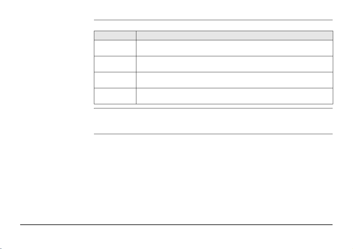
Symbols The symbols used in this manual have the following meanings:
Type Description
Danger Indicates an imminently hazardous situation which, if not avoided, will
Warning Indicates a potentially hazardous situation or an unintended use which, if
Caution Indicates a potentially hazardous situation or an unintended use which, if
Validity of this manual This manual applies to all EZiSYSTEM instruments, which are the i-Series locators, the t-
Series transmitters and accessories. Differences between the various instruments and
models are marked and described.
result in death or serious injury.
not avoided, could result in death or serious injury.
not avoided, may result in minor or moderate injury.
Important paragraphs which must be adhered to in practice as they enable
the product to be used in a technically correct and efficient manner.
EZiSYSTEM, Introduction 3

Table of Contents
In this manual Chapter Page
1 General Information 7
1.1 How to Use this Manual 7
1.2 i-Series General Information 8
1.3 i-Series Instruments and Accessories 10
2 How to Use the Locator 11
2.1 General Information 11
2.2 Locator Overview 13
2.3 Locator Setup and Information 16
2.4 Hazard Zone 19
2.5 How to Locate a Service 21
2.6 Wireless Data Communication, where applicable 34
2.7 Memory & Communication 37
2.8 Internal GPS 38
3 How to Use the Transmitter 40
3.1 General information 40
3.2 Transmitter Overview 42
3.3 How to Locate a Service Using the Transmitter 45
4 How to Use the Conductive Rod 49
4EZiSYSTEM, Table of Contents
4.1 General Information 49
4.2 Conductive Rod Overview 49
4.3 How to Locate a Service Using the Conductive Rod 50

5 How to Use the Signal Clamp 52
5.1 General Information 52
5.2 Signal Clamp Overview 52
5.3 How to Locate a Service Using the Signal Clamp 53
6 How to Use the Property Connection Set 55
6.1 General Information 55
6.2 Property Connection Set Overview 55
6.3 How to Locate a Service Using the Property Connection Set 56
7 How to Use the Sonde 58
7.1 General Information 58
7.2 Sonde Overview 58
7.3 Maxi Sonde Overview 61
7.4 How to Locate a Service Using the Sonde 64
8 Care and Transport 66
8.1 Transport 66
8.2 Storage 66
8.3 Cleaning and Drying 67
9 Safety Directions 68
9.1 General Introduction 68
9.2 Intended Use 68
9.3 Limits of Use 69
9.4 Responsibilities 69
9.5 Hazards of Use 70
9.6 Electromagnetic Compatibility EMC 75
9.7 FCC Statement, Applicable in U.S. 78
EZiSYSTEM, Table of Contents 5

10 Technical Data 83
10.1 Locator i-Series Technical Data 83
10.2 Transmitter Technical Data (1 Watt models) 88
10.3 Conductive Rod Technical Data 91
10.4 Sonde Technical Data 93
10.5 Maxi Sonde Technical Data 95
10.6 Property Connection Set Technical Data 97
10.7 Signal Clamp Technical Data 99
10.8 Multi Clamp Technical Data 101
11 International Limited Warranty 103
Appendix A Functional Checks 104
A.1 Locator Functional Check 104
A.2 Transmitter Functional Check 108
A.3 Conductive Rod Functional Check 114
A.4 Sonde Functional Check 116
Appendix B World Frequency Zones 119
Index 123
6EZiSYSTEM, Table of Contents

1 General Information
1.1 How to Use this Manual
It is recommended to set up the product while reading through this manual.
Naming convention EZiCAT i500, i550, i600, i650, i700, i750 and xf models are hereinafter referred to as Locator.
Differences between the models are marked and described.
EZiTEX t100, t300 and xf models is hereinafter referred to as Transmitter.
EZiROD is hereinafter referred to as Conductive Rod.
Index The index is at the back of the manual.
Instrument label On the Locator and Transmitter you will find a label that shows some important informa-
tion by means of illustrations. You will find some of these illustrations in this manual too.
This should help to get a clear connection between the instrument label and the information in this manual.
EZiSYSTEM, General Information 7

1.2 i-Series General Information
Description Locators are used to detect buried conductive services emitting an electromagnetic signal
which is generated by a current passing through the service.
Transmitters are used to apply a distinct signal to conductive services, which may not
radiate electromagnetic signals or may need to be traced for a specific purpose.
The Transmitter is required to make a depth or current measurement.
The Locators and Transmitters described within this manual will greatly increase the detection process and help to reduce the dangers and costs associated with service strikes. But
the very nature of electromagnetic location is dependent on the services being conductive
(metallic) and radiating a signal as current flows through them.
It is important to remember that a Locator on its own will not detect all services and care
should be taken when excavating. It is generally accepted that a safe system of work should
be adopted which would include planning the work in advance, the use of utility maps, the
use of Locators and Transmitters, and the use of safe digging practices.
Caution The absence of a positive indication does not guarantee the non-existence of a service.
Services without a detectable signal may be present.
The Locators can only locate non-metallic services such as plastic pipes, typically used by
the water and gas utilities, with the use of appropriate accessories.
Precautions:
Always excavate with care.
8EZiSYSTEM, General Information

Accessories Designed to increase the detection of services with no (or little) signals on them. Generally
work in conjunction with the Locator and Transmitter.
Functional Check Designed to demonstrate the equipment is working satisfactorily in between service inter-
vals. Refer to "Appendix A Functional Checks" for more information.
EZiSYSTEM, General Information 9

1.3 i-Series Instruments and Accessories
General information The i-Series is a collection of products used to locate buried metallic and nonmetallic
services.
10EZiSYSTEM, General Information
i-Series instruments
overview
i-Series accessories
overview
F
i
ab
acb
d
ef
g
a) Locator
b) Transmitter
a) Conductive Rod (non
metallic service tracer)
b) Extension Cable
c) Property Connection
Set
d) Signal Clamp
e) Multi Clamp
f) Sonde
g) Maxi Sonde

2 How to Use the Locator
2.1 General Information
Operating modes • Passive modes: Power and Radio
• Active modes: 8 kHz, 33 kHz, additionally 512 Hz and 640 Hz on xf models
• Auto mode: Combined Power and Radio modes
Electromagnetic signals An electromagnetic signal radiates from buried conductive services as an electrical current
flows through them. The Locator processes these signals and displays their presence.
Passive signals Some signals are already present on buried services and can be readily detected by the
Locator. We call these passive signals. These signals are generated by power distribution
systems and radio transmitters.
Active tracing Some conductive services do not emit passive signals. These services may be traced by
applying a signal to the service by using a transmitter.
Depth indication
(i550, i650, i750, i550xf,
i650xf, i750xf)
Current Measurement
(i550xf, i650xf & i750xf)
Wireless communication
(Bluetooth)
EZiSYSTEM, How to Use the Locator 11
Depth indication is only available with the i550, i650, i750, i550xf, i650xf, i750xf locators
when used in conjunction with the Transmitter or Sonde. The displayed depth is to the
centre of the service or to the Sonde.
Current measurement is only available on the i550xf, i650xf or i750xf when used in
conjunction with the transmitter. The highest current reading (mA) will be displayed over
the service which has the transmitter connected to it.
Data can be wirelessly transferred from the Bluetooth enabled Locator to devices which are
designed to accept the information.

12EZiSYSTEM, How to Use the Locator
Hazard zone Provides an additional alarm, indicating the close proximity of a service emitting a Power,
8 kHz, 33 kHz (512 Hz and 640 Hz on xf models) signal.
Peak hold Assists in pinpointing a service by displaying the peak reading for a short period of time.

2.2 Locator Overview
Locator main parts
F
i
The case foot can be replaced if it is worn. Contact your agency or Cable Detection authorised service workshop.
a
b
c
d
e
a) Display Panel
Contains the operational controls.
b) Speakers (mounted internally left and right)
Active at power on and when a signal is detected.
c) On/Off Trigger
Press and hold the trigger to activate the Locator.
Release the trigger to deactivate.
d) Battery Hatch Release
Pressing the release button unlocks the battery
hatch allowing access to the battery compartment.
e) Battery Compartment
6 x LR6 (AA) alkaline batteries are used. Replace all
f
batteries when indicated.
f) Case Foot
EZiSYSTEM, How to Use the Locator 13
14EZiSYSTEM, How to Use the Locator
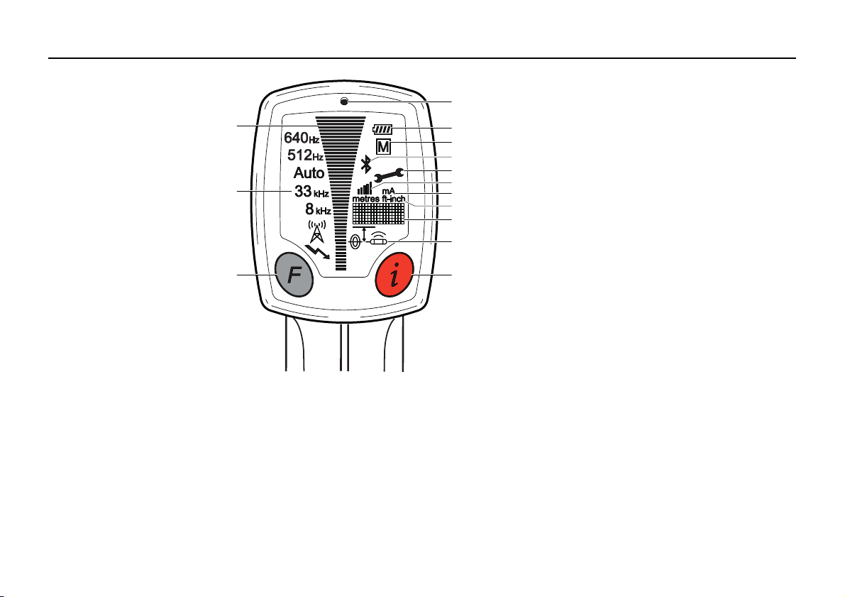
Display panel overview
a) Signal Strength Indicator
Indicates the response of the Locator to a signal
d
(service).
a
b
c
g) Bluetooth Status Indicator
Symbol Static: Bluetooth is enabled
Symbol Flashing: Bluetooth is paired
No Symbol: Bluetooth is disabled
h) Wrench
Indicates the Locator requires periodic service or unit is faulty.
b) Mode Indicators
e
Displays the selected mode: Power, Radio, 8 kHz,
f
33 kHz, Auto,
g
A
h
i
j
k
l
m
n
s shown, from bottom to top.
c) Function Button
Selects operating mode.
d) Light Sensor
Automatically switches the displays backlight on
or off to suit light conditions.
e) Battery Indicator
Indicates the battery condition. Segment illumination decreases as battery condition declines.
Replace the batteries when the battery indicator is
empty.
f) M Indicator
Symbol Static: Memory enabled
GPS índicator (i700, i750, i750xf)
Symbol Flashing: GPS active and recording GPS
coordinates.
Symbol Static: No GPS position.
(512 Hz and 640 Hz on xf models).

i) Numeric Signal Strength Indicator (SSI)
Symbol Static: SSI is enabled
No Symbol: SSI is disabled
j) Current Indicator (i550xf, i650xf and i750xf)
Indicates the amount current flowing through a service which is applied by the Transmitter.
This is measured in milliamperes (mA).
k) Measurement Unit (Depth indication with the i550, i650, i550xf, i650xf and i750xf)
Indicates depth indication is in metric or feet and inches.
l) Display Readout
Alpha numeric matrix indicates system set up and depth indication.
m) Depth Mode Indicators
Indicates a depth reading to a service or a Sonde (Depth locators only). Service depth icon
used to indicate Hazard Zone status.
n) i Button
Used to access the user settings and to provide a depth readout for Depth locators.
EZiSYSTEM, How to Use the Locator 15
2.3 Locator Setup and Information
16EZiSYSTEM, How to Use the Locator
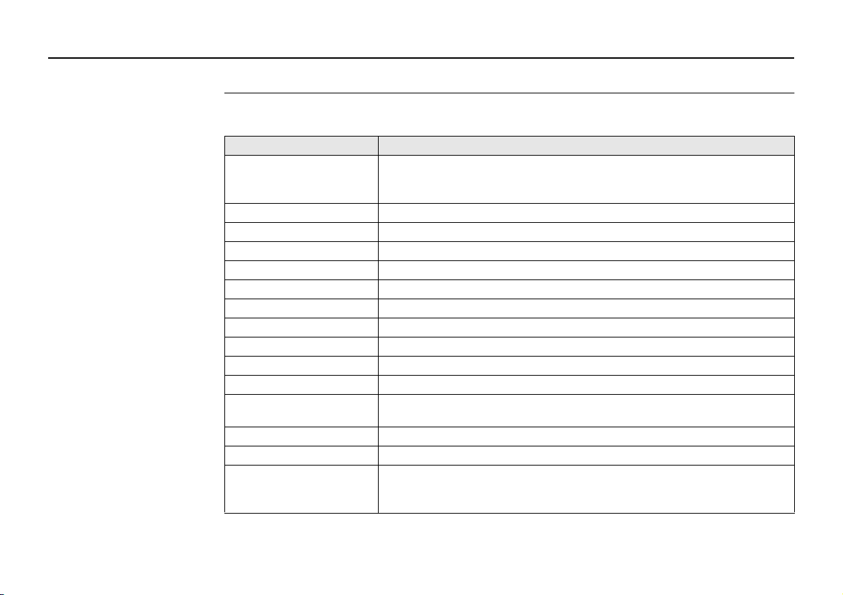
Locator settings The i-Series Locators offer a range of settings which the operator can adjust to their own
preference. It also displays additional service and contact information as detailed.
Setting Description
EST Performs a function check on the locators hardware and software,
displaying PAS if the Locator is within predefined tolerance or
ERR if the locator is not.
H.Z Switches hazard zone on or off.
VOL Adjust volume level (0 - 10).
HLD Adjust peak hold duration (0 - 5 seconds).
SSI Displays a numeric signal strength indicator.
CST Adjusts display’s contrast (0 - 15).
M/I Displays unit of measurement.
CAL Displays the next service date DD/MM/YY.
CON Displays supplier/company name.
TEL Displays supplier/company telephone number.
I.D Displays the operator’s name.
PWR Displays the power mode regional setting. Refer to "Appendix B
World Frequency Zones" for more information.
SR# Displays unit serial number.
VER Displays software version.
CLK
(i600, i650, i700, i750,
i600xf, i650xf, i750xf)
Displays the date and time held within the locators memory.
Format DD/MM/YY/HH/MM/SS.

Setting Description
LOG
Displays the last stored log number 001 to 999.
(i600, i650, i700, i750,
i600xf, i650xf, i750xf)
BT
Adjusts the Bluetooth output options.
(i600, i650, i600xf &
i650xf)
Setting COM
(i700, i750 & i750xf)
Adjusts the locators Bluetooth or GPS settings:
PC: Enables Bluetooth communication to Logicat Software
BT1: Enables Bluetooth option 1 (refer to section 2.6)
BT2: Enables Bluetooth option 2 (refer to section 2.6)
GPS: Switches GPS on following use with BT1 or BT2 settings
LST
(xf models)
Sets the Locators start up mode.
On: The Locator starts in the last mode of operation used.
Off: The Locator starts in Power mode.
Accessing and adjusting
the settings
1. Switch the Locator on.
2. Ensure the Locator is in Power mode.
If required, press Function Button to select mode.
3. Depress the i Button until the user settings are displayed in the display readout.
4. Press Function Button to toggle through to desired setting.
5. Press i Button to select the setting.
6. Press Function Button to activate/adjust.
7. Press i Button to store and exit.
EZiSYSTEM, How to Use the Locator 17
Danger The Locator may fail to detect electrical services in Power mode if an incorrect power
setting is used.
Precautions:
Before use, verify the Locator is setup to be compatible with mains frequency supply in
your country. Options are 50 or 60 Hz. Refer to "Appendix B World Frequency Zones" for
more information.
Contact your agency or Cable Detection authorised service workshop if your unit is incorrectly configured for your region.
18EZiSYSTEM, How to Use the Locator
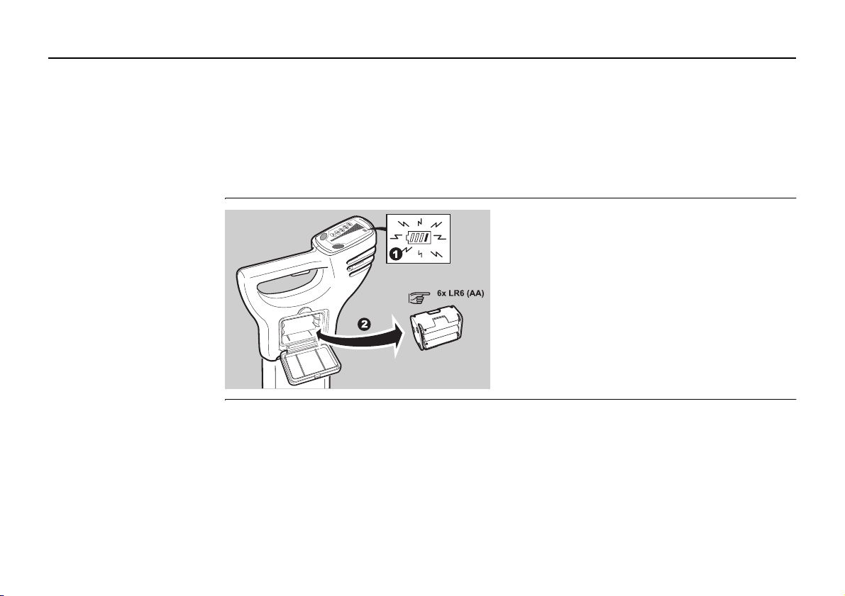
Changing the battery
1. Replace or Recharge the batteries when
F
i
the battery status indicator is empty.
2. Press the release button to unlock the
Battery Hatch. Remove the battery
holder from the Locator.
3. Replace all batteries with six new
LR6 (AA) type alkaline batteries, or
remove and recharge the battery pack if
rechargeable batteries are fitted.
2.4 Hazard Zone
Description Provides an additional warning to the close proximity of buried services and functions in
the following modes:
•Power
• 8 kHz
• 33 kHz
• Auto mode (Power mode only)
• 512 Hz & 640 Hz (xf models only)
Hazard zone
status indicators
EZiSYSTEM, How to Use the Locator 19
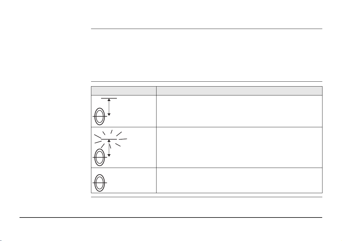
Status indicator Description
Hazard zone is switched on.
Hazard zone on and is alarming.
Hazard zone is switched off.

Caution The absence of a positive indication does not guarantee the non-existence of a service.
Services without a detectable signal may be present.
The Locators can only locate non-metallic services such as plastic pipes, typically used by
the water and gas utilities, with the use of appropriate accessories.
Precautions:
Always excavate with care.
20EZiSYSTEM, How to Use the Locator

2.5 How to Locate a Service
Start up test The following test sequence will take place every time the Locator is activated.
On test Test pattern Info on label
Audio Output On throughout test
sequence
Signal Strength indicator
Mode indicators Briefly illuminated
Indicator Icons Briefly illuminated
Battery indicator On throughout test
GPS Search Mode (i700, i750 & i750xf)
A GPS search mode is activated as part of the start up test allowing the internal GPS
module time to search for a GPS position. GPS search mode is active following the start up
test even if the locator is off, the search mode will stop when a GPS position is obtained or
a 12 minute search period has elapsed.
Scrolls through in
sequence once
sequence
GPS search mode does not affect the locators performance and the locator can be used as
normal throughout this search mode.
EZiSYSTEM, How to Use the Locator 21
Locating process The locating process is split into three steps:
• Sweep Search
• Pinpointing the service
• Direction of the service
22EZiSYSTEM, How to Use the Locator
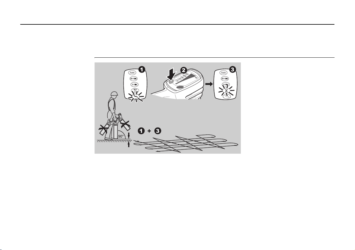
Sweep Search
Auto mode combines the
benefit of simultaneous
F
i
Define the area to be excavated.
1. In Power mode cross the site from left to right keeping the Locator upright, taking
care not to swing the unit. Turn through 90 degrees and repeat.
Ensure that the Locator is held in an upright position and close to the ground.
2. Continue the sweep until either a signal is located or you are satisfied that the area
has been adequately tested.
In the presence of a service emitting a traceable signal a tone will be emitted
and the signal strength indicator will rise and fall as you pass over it.
detection in Power and
Radio modes and helps to
confirm the presence of
services upon initial site
occupation. Improved definition of the service will be
provided by single mode
operation.
3. Repeat the Sweep Search process in Radio mode.
The Sweep Search must be conducted in Power and Radio modes as a
minimum, as not all services (including some electrical ones) emit a power
signal. These services may be found using Radio mode or active modes.
Hazard zone can be operated in Power, 8 kHz, 33 kHz and Auto (512 Hz and
640 Hz on xf models) modes and provides an additional alarm to the presence
of buried services which may be within close proximity.
Pinpointing the service
EZiSYSTEM, How to Use the Locator 23
• Mark services with marker paint, pegs, flags or similar. Never drive pegs into the ground
over the service.
• The signal strength indicator does not indicate the size, depth or type of a service.
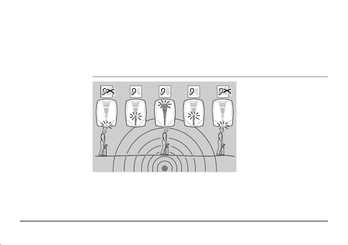
Retrace your steps to the area
where the highest signal reading
(peak response) was obtained.
The service is directly below the
Locator when the signal strength
indicator is at its maximum. The
audio output will automatically
adjust to facilitate pinpointing
over the service, and automatically reset when the signal
strength indicator drops to its
minimum position.
24EZiSYSTEM, How to Use the Locator
Peak hold
When activated peak hold will show the highest peak reading obtained during the pinpoint
process. The displayed reading can be adjusted between 0 to 5 seconds.
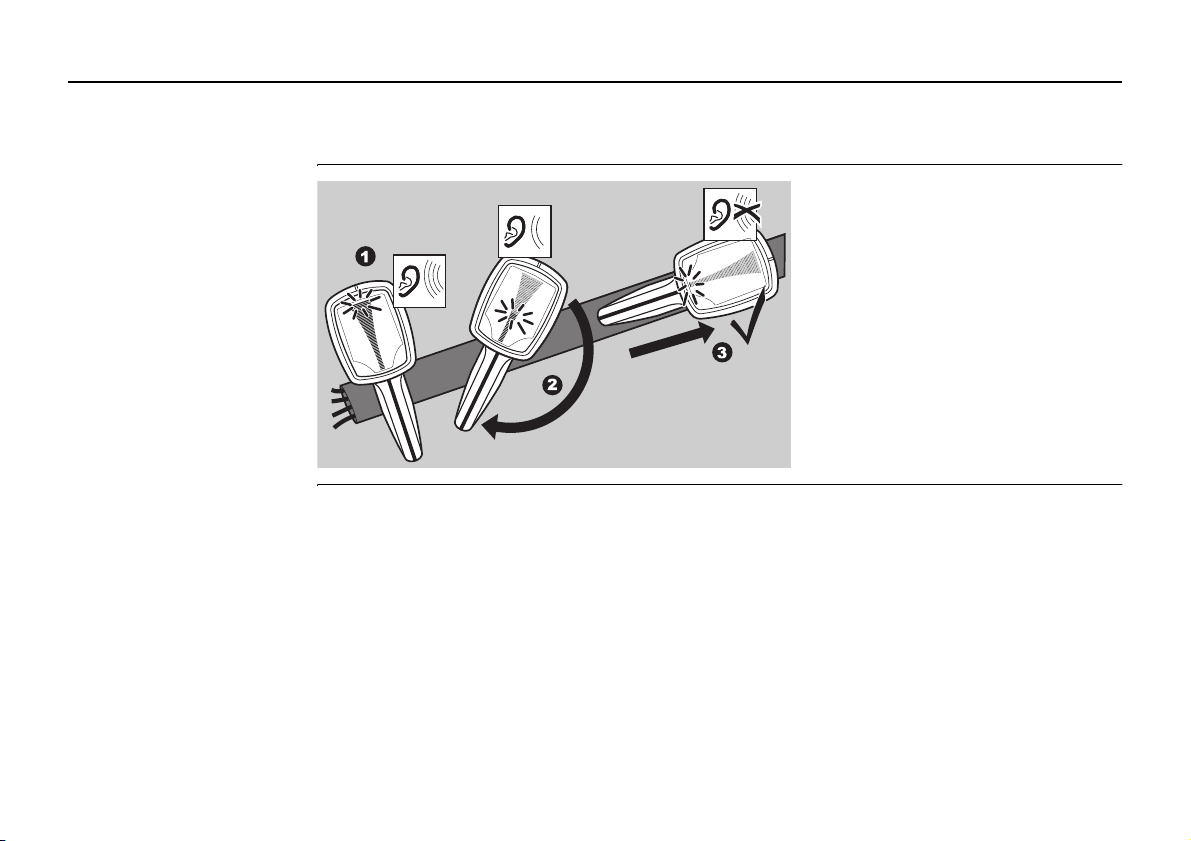
Detecting direction of the
service
1. Position the Locator directly
over the service.
2. Rotate the Locator on its axis.
3. The blade of the Locator will be
in line with the service when
the signal strength indicator is
at its minimum.
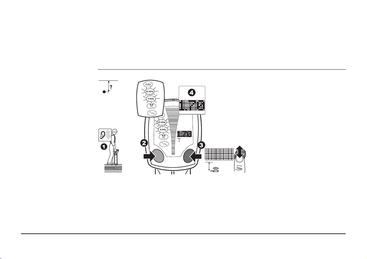
Depth Indication
(i550, i650, i750, i550xf,
i650xf and i750xf)
1. Apply a signal to the service.
Refer to "3 How to Use the
Transmitter" for more information.
2. Select the mode to suit the
Transmitter’s output. Position
the Locator directly over, and
at 90 degrees to the direction
of the service.
3. Press and release the i Button.
4. The display readout will indi-
F
i
i
cate the depth of the service
and the Line mode icon will be
displayed.
EZiSYSTEM, How to Use the Locator 25
• Activating Sonde depth will provide an inaccurate readout.
• Mark utilities with marker paint, pegs, flags or similar. Never drive pegs into the ground
over the service
• Additional services may be within the excavation zone, as well as the service you are
taking a depth reading from.
• The reading will be more accurate when taken over a straight run, where the service
does not bend, or have a service crossing it or coming off it.
• An additional depth reading should be taken with the locator lifted off the ground by
approximately 100 mm (4 inches). The reading obtained should confirm the addition of
this height.
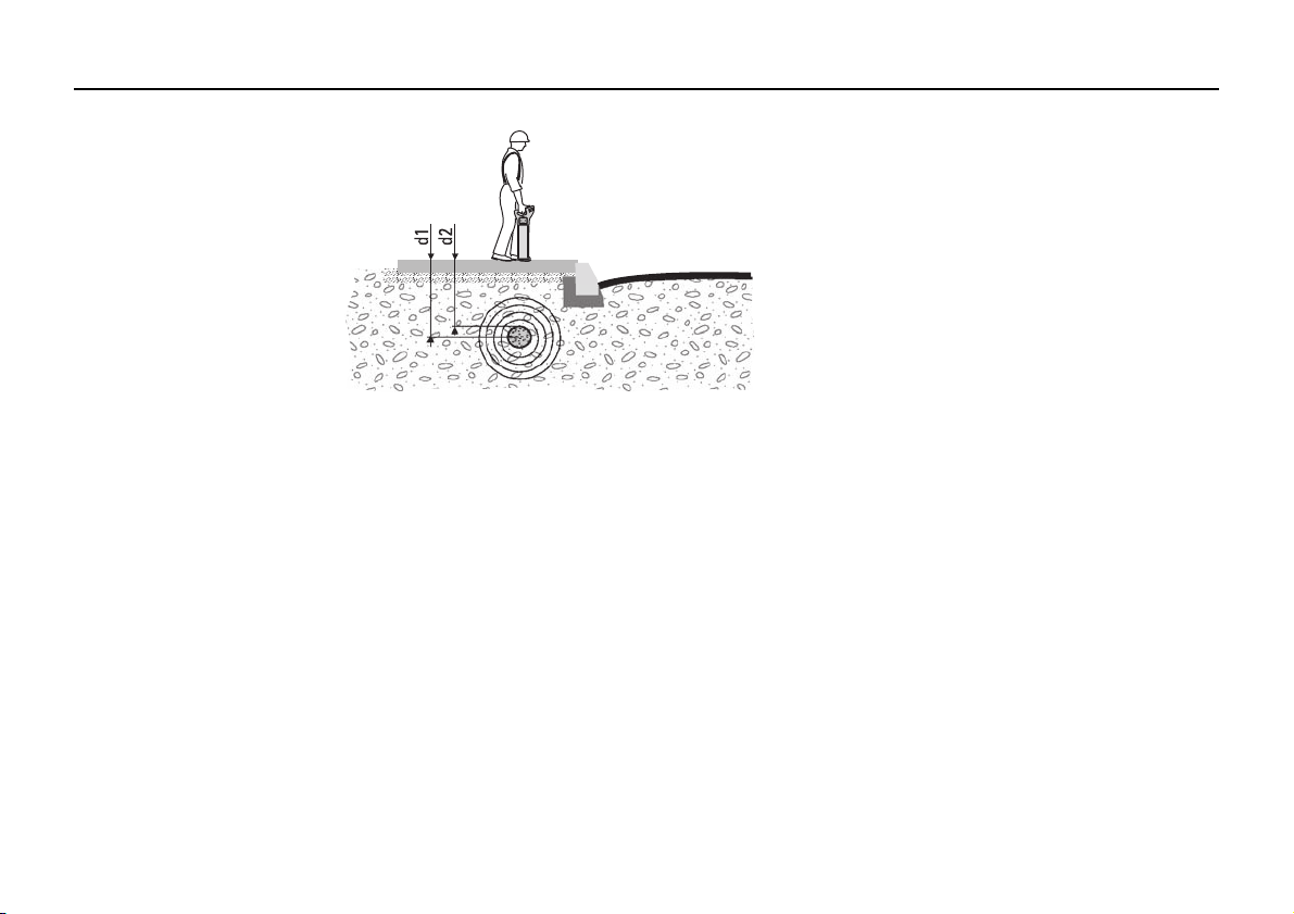
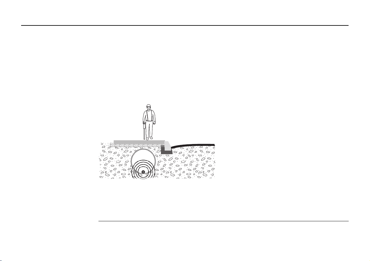
Depth shown and actual depth:
26EZiSYSTEM, How to Use the Locator
d1 Depth shown on the EZiCAT = depth to the
centre of the line.
d2 Actual depth of the service.
Note the difference between d1 and d2!
Warning The depth reading might not reflect the real depth if your Locator picks up the signal
i
F
i
induced into the service by the Transmitter. This signal is radiated from the centre of the
service.
This is even more important when the signal is produced by a Sonde, lying in a large diameter conduit!
Precautions:
Always compensate depth reading for service size.
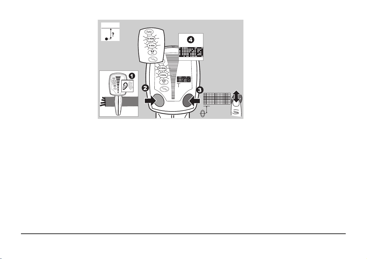
Measuring Sonde depth
(i550, i650, i750, i550xf,
i650xf and i750xf)
EZiSYSTEM, How to Use the Locator 27
1. Switch on the sonde and set to
the required frequency. Refer
to "7 How to Use the Sonde" for
more information.
2. Select the mode to suit the
Sonde’s output.
Position the Locator directly
over, and in line with the
Sonde. Refer to "7 How to Use
the Sonde" for more information.
3. Press and hold down the
i Button for 2 seconds until the
dashed lines have scrolled
through once.
4. The display readout will indicate the depth of the Sonde
and the Sonde mode icon will
be displayed.
28EZiSYSTEM, How to Use the Locator
Warning The depth reading may not indicate the real depth of the service, especially if the sonde is
• Activating line depth will provide an inaccurate readout.
• Mark utilities with marker paint, pegs, flags or similar. Never drive pegs into the ground
over the service.
• Additional services may be within the excavation zone, as well as the service you are
taking a depth reading from.
• An additional depth reading should be taken with the locator lifted off the ground by
approximately 100 mm (4 inches). The reading obtained should confirm the addition of
this height.
Depth shown and diameter:
Take special care when the signal is produced
by a sonde, lying in a large diameter conduit!
lying at the base of a large diameter duct.
Precautions:
Always compensate depth reading for service size.
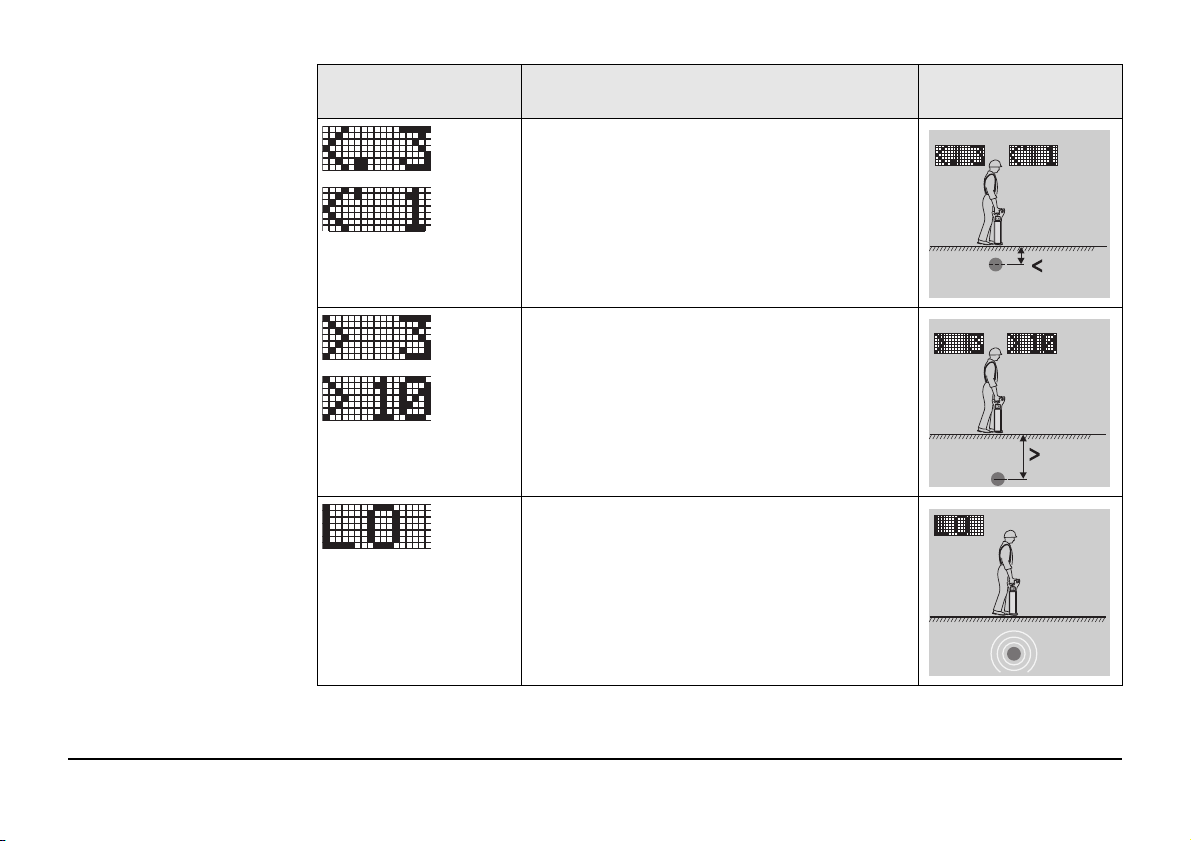
Depth code information
0.3 m
1ft
metres ft-inch
Information code Description Information on instru-
ment label
The service is too shallow to register prop-
metres
ft-inch
erly.
EZiSYSTEM, How to Use the Locator 29
metres
ft-inch
The service is too deep.
The signal received by the Locator is too
small to register properly.
metres ft-inch
3.0 m
10ft

Information code Description Information on instru-
ment label
The signal received by the Locator is too
large to register properly.
Depth function not available. The Locator is
set to the wrong mode for a depth reading
to be taken.
30EZiSYSTEM, How to Use the Locator
 Loading...