

Page 1

E-BIKE USER GUIDE
Page 2

02
Customer Services: 01484 506 123
visit ezego.bike for more products and accessories
Page 3

CONTENTS
1. WELCOME
2. SAFETY
3. RIDING
4. ASSEMBLY
4.1 RIDING POSITION
4.2 POWERING UP YOUR E-BIKE
4.3 PEDAL ASSEMBLY
4.4 FOLDING MECHANISMS
4.5 HANDLEBARS AND STEMS
4.6 GEARS
4.7 DISC BRAKES
4.8 MUDGUARDS
5. WARRANTY
13
15
17
18
21
25
29
33
4.9 WHEELS
4.10 SADDLE AND SEATPOST
4.11 BATTERIES
4.12 DISPLAY
4.13 READY TO RIDE! - FINAL INSPECTION
4.14 TORQUE SPECIFICATIONS
4.15 MAINTENANCE OF YOUR INVESTMENT
4
6
9
12
34
44
49
56
57
58
59
62
03
Page 4

1. WELCOME
Thank you for your purchase of your brand new EZEGO electric bicycle.
This manual is designed for our PAS specic electric bicycle systems. PAS is an acronym for “Pedal Assist”
System, and is how it is recognised in the UK and EU.
No pedaling, no power: The complete electric system comprises of a battery, motor, controller, sensor,
display and cables, and is designed to follow the legal laws within the UK and EU. This means that the
electric system will only engage and provide power when pedaling.
When the rider stops pedaling, or applies the brakes, the power to the motor will cut-off. The amount
of power that is sent to the motor depends on the assist level selected on the handlebar display.
Your electric bicycle is designed for 5 levels assist, level 1 providing the least power, level 5 the highest. It is
worth noting that riding in a higher level will drain your battery much faster than riding in a lower level,
so it is a good idea to get used to when and where the extra power is required.
The system is also designed by law to cut-off if pedaling speed reaches 25km/h (15.5 mph). Once the
speed drops below 25km/h (15.5 mph), the power to the motor will re-engage if pedaling, or once
pedaling commences again.
Your electric bicycle can also be used and ridden with the electric system switched off, just like a regular
bicycle. It will work exactly in the same manner when the electric system is disabled.
Please note that this manual provided with your purchase is not intended as a comprehensive
maintenance, service or repair manual. We always recommend that your electric bicycle is regularly
serviced by a qualied service bicycle mechanic. If ever in doubt about the state or service of your electric
bicycle, always consult a qualied bicycle shop and/or mechanic.
Throughout this instruction manual we will alert you to certain warnings and cautions, where we
recommend attention to maintenance, inspection of condition, or the need to follow safe cycling
practices. These alerts will be marked with the following symbol:
04
Page 5
These warnings and cautions are there to advise you that “you may lose control and fall”. As any fall can
result in serious injury, or death, this warning is not always repeated.
It is impossible to anticipate all situations or conditions when you are riding, so this manual makes no
representation about the safe use of the electric bicycle under every condition or circumstance. There
are risks associated with the use of any electric bicycle, which cannot be anticipated, and thus is the sole
responsibility of the rider.
It is illegal for any children under the age of 14 to ride an electric bicycle.
05
Page 6
2. SAFETY
Firstly, we would like to bring to your attention some very important safety
information. Whether you are a seasoned cyclist, or new to cycling, as a brand
that prides itself on safety we cannot over-stress the importance of wearing
a bicycle helmet when riding your bike. The Highway code strongly advises
wearing a helmet “which conforms to current regulations, is the correct size and
securely fastened.”
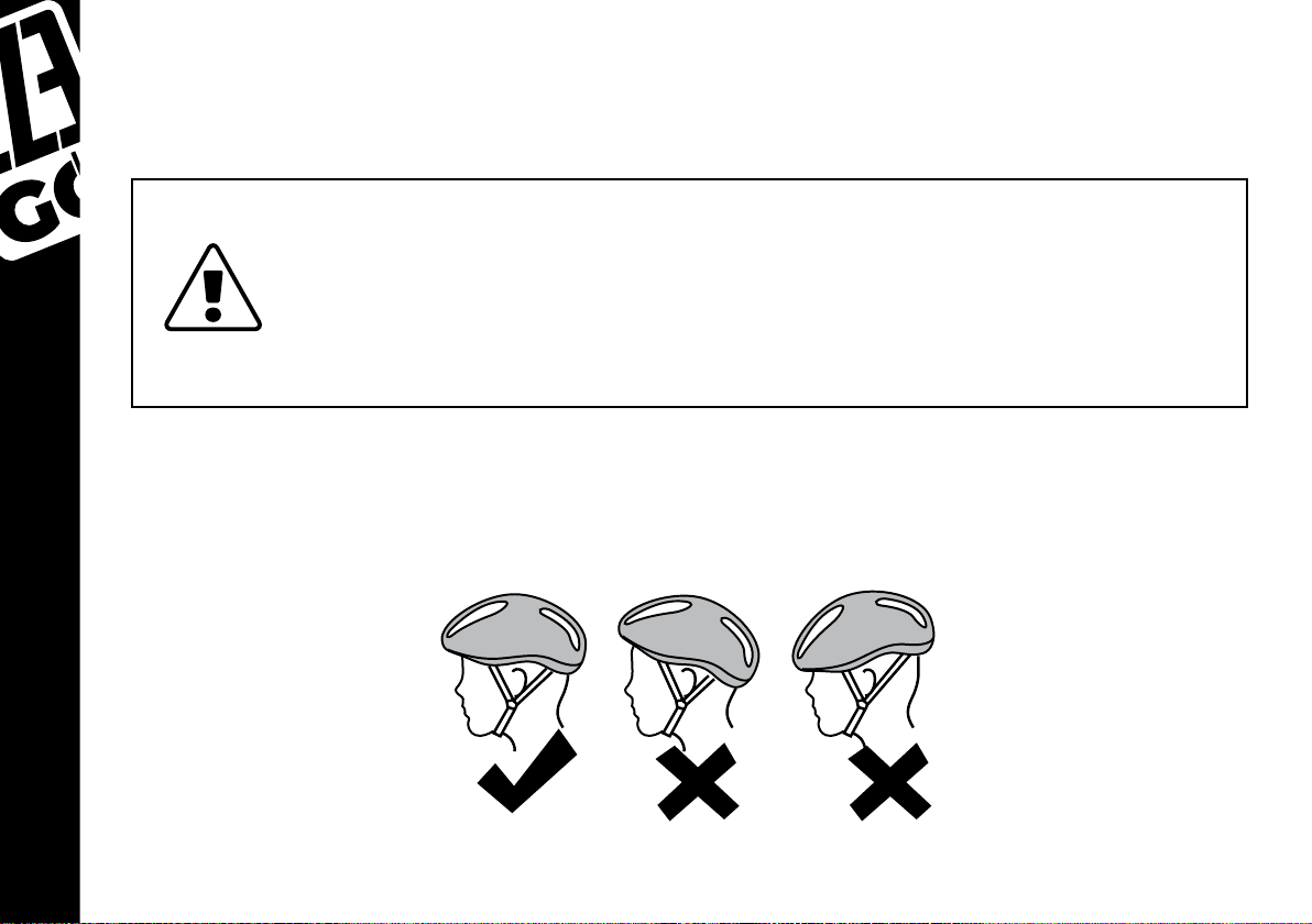
Always wear a cycling helmet which meets the latest certication standards, and is appropriate
for the type of riding you do. Always follow the helmet manufacturer’s instructions for its tting, use,
and care. A properly tted helmet should cover the forehead when riding an e-bike. Most serious e-bike
injuries involve head injuries, which might have been avoided if the rider had worn an appropriate
helmet.
06
Page 7

Safety equipment is also available to protect knees, elbows, backs, shoulders and your eyes. Use of such
gear is highly recommended. You should ensure you always wear appropriate clothing that is bright,
visible, and not too loose. Loose clothing may snag in moving parts, causing you to lose control and fall.
Be sure to dress in accordance with weather conditions. Your footwear should be able to grip the pedals
and should not have loose laces. When night riding, or in dark weather, ensure you conform to all laws
regarding lighting and clothing, and be aware that cyclists are often difcult to spot for both drivers and
pedestrians.
Local Trafc Laws:
Make sure you know all local trafc laws and conform to them. You are sharing the road with others,
and you should always assume that they haven’t seen you. Use caution on busy roads and around large
vehicles. Cycling is no different to any other sport, there is always a risk of injury to yourself, others or
property. The responsibility of the risk is yours, so please make yourself aware of the rules and regulations
as a road user. Riding off-road, may require extra attention and specic skills. Get to know your e-bike
well before using increased speed or riding in difcult terrain.
Visibility:
Your e-bike is tted with front & rear reectors, pedal reectors, as well as 2 wheel reectors. These
are specically designed to assist with evening/night riding. All these reectors are produced to British
Standards, and are designed to reect street lights and car head lights in order to help recognise you as
a moving cyclist. Always check that these reectors are properly tted, xing bolts tightened, and any
damaged parts must be replaced by a cycle shop.
If you have tted any lights to your e-bike, please make sure that they are working properly, and that
they conform to legal requirements. Please take care when riding at night time, and that you are visible
to others. We don’t recommend riding at night time, which is why we don’t include lights with these
products.
Any form of jump, stunt, wheelies, race/competition, or extreme riding of any kind will invalidate
your warranty.
07
Page 8
We recommend that your rst ride is taken in a controlled format, away from
vehicles, obstacles and other cyclists etc., to ensure you become familiar with
the controls and features of your new electric bicycle, in particular, the brake
performance. If you feel anything about the electric bicycle is not as it should be,
consult a qualied bicycle mechanic.
Be aware that during wet / snowy / icy conditions, braking efciency of ALL road
trafc is greatly reduced.
08
Page 9
3. RIDING
From this point, your manual may refer to your electric bicycle as an e-bike.
It is vital you understand your new electric bicycle by reading this manual carefully before your rst ride.
Do this, and you will be capable of achieving better performance, comfort, and pleasure from your new
e-bike.
Regular maintenance and proper use of your electric bicycle will also reduce risk of injury or
damage to property.
Do not allow water to get into the electric components, including rain, and water
formations such as puddles, potholes, streams & rivers, and including spillages
such as drinking water, coffee, etc..
Tips for riding your new e-bike, to help save your battery:
The battery makes a difference. Properly maintaining your battery, and charging it correctly
1.
will help to prolong it’s lifespan. Don’t keep your battery stored in cold conditions, as this will
degrade it, and frozen conditions can permanently damage it.
Terrain makes a difference. The smoother the surface of the terrain, the less energy will be
2.
expended by the battery compared to riding on rough terrain.
The weather makes a difference. Cold temperatures can reduce the performance of the battery,
3.
just as headwinds reduces the performance of the rider.
Elevation make a difference. Riding up hills and slopes will drain the battery much quicker
4.
compared to at surfaces, and more so than downhill slopes.
09
Page 10

The rider can make a difference. Helping the electric system by using lower levels of power
5.
assist, and instead using your legs to power the e-bike more, will help the battery life last longer
while riding.
Braking makes a difference. Practice using your brakes to get used to their power and how
6.
they control the e-bike. The less you brake, and stop/ start, the less energy is wasted by having
to increase speed up again. This by no means that you should ride your e-bike in an unsafe
manner without braking properly.
Weight makes a difference. The average range of the battery is 60km per charge. This is based
7.
on an average rider weight of 75kg. The more weight or cargo on the e-bike, the more the
battery will drain quicker.
Maintenance make a difference. The better maintained your electric bicycle, the better it will
8.
work and reduce wasted energy.
Tyres make a difference. Make sure your tyres are inated to the correct PSI and have no issues
9.
with wear and tear. Tyres with low amounts of air, or damage to the tread will cause more
friction, which requires more energy from the battery.
Your EZEGO battery, the heart of your e-bike:
Your battery is one of the most important components on your e-bike. Looking after your battery properly
will ensure longevity of its life, and it will continue to perform at the levels it should.
10
Ensure that your battery is fully charged before rst use. For more information on
charging please refer to page 52
Page 11
Your battery is also equipped with a “smart battery management system” which enables such features
as “sleep mode”. This feature will allow your battery to “sleep” for longer periods of time without charging.
Please note, to ensure that your battery is at least 50% full before allowing it
to sleep for long periods of time. We recommend that you do not allow your
battery to sleep for a period longer than 6 months, otherwise the battery cells
can disperse their energy over such time, and not be able to re-charge again. For
more information on sleep mode function, please refer to page 54 of this manual.
For a better commuting experience, many users will purchase a second battery, and even a second
charge to keep in another location. Such accessories can be found in our online store at:
www.ezego.bike/accessories
11
Page 12

4. ASSEMBLY
Important: Pedal Assembly – Please read pedal assembly guide on page 17, failure
to assemble correctly may result in cross-threading key components causing
irreparable damage not covered by warranty.
Remove all packaging materials. Please keep these materials until you are satised that your e-bike is
setup correctly, and in good working order. If you make the decision to dispose of the packaging before
such time, there may be costs incurred for new packaging if the product needs to be returned to us.
When opening the carton containing your electric bicycle, please take care not to puncture through the
cardboard and damage your e-bike. Also take care with plastic handles, staples, and carton banding.
Prepare by setting all parts aside for assembly.
Whether a folding, or non-folding model, some minimal assembly will be required to prepare your e-bike
for riding. Please follow the guidelines over the next few chapters for correct assembly instructions.
Tools provided include: 4/ 5/6mm hex (allen) keys, 8/10/14/15mm spanner
Tools required may include: crosshead screwdriver, cutters/pliers.
12
Page 13
4.1. RIDING POSITION
Firstly, it is very important that you can mount, dismount, and ride your e-bike safely, and ride in a
comfortable position whilst enabling you to access its features and safety components (such as brakes,
gears and display) without obstruction. The following section will help you to achieve that perfect riding
position.
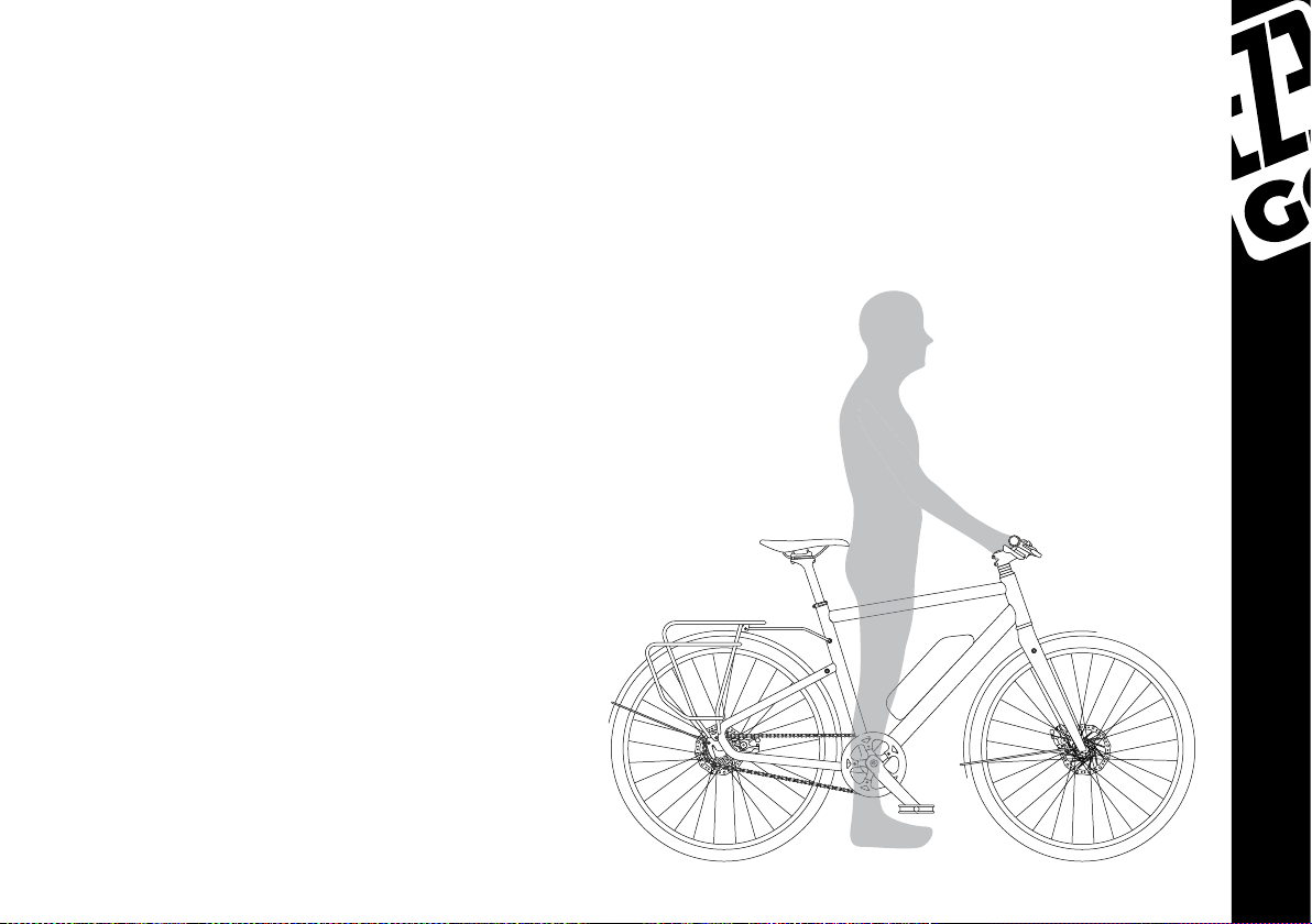
Start off by standing over your e-bike, with the frame between your legs, and saddle positioned behind
you. If you are using a ladies specic frame with
a sloped top tube, try to imagine the top tube a
little higher as you would see on a gents model.
Our products are mainly designed for road and
at use, but depending on your requirements
you can use the clearance levels below to guide
you:
Flat, road, paved surfaces should require a 5mm
clearance from top tube to groin.
For more uneven surfaces, such as canal paths,
it is better to have a clearance of around 7.5mm
from top tube to groin.
If you decide to take your e-bike off road, it is
recommended to give yourself a little more
clearance of 10mm from top tube to groin.
When riding, you should make sure that your
elbows are slightly bent, your legs do not overextend - locking your knees - and that your
knees should not go past a 90 degree angle past
your thighs when coming back up though the
pedal cycle. To help achieve this you can adjust
your saddle height so that foot to pedal (not foot
13
Page 14
to oor) your leg should be almost straight with your knee slightly bent. From this position you may not
be able to reach the oor, but by just moving back and forth off from the saddle you can easily do so
comfortably.
It is important to set up your saddle height in order to avoid unnatural movements of your legs, and
more specically your knees if positioned too low. If the saddle is positioned too high, then your knees
can lock out causing pain and long term injury. In both instances, it is far more difcult to control your
e-bike, which puts you and others around you in danger.
To adjust the saddle height, please refer to page 44 of this manual.
When setting your riding position, it is very important that you do not exceed the
“minimum insertion” mark on your seat post or stem (where applicable). You will
nd warnings on these along with diagrams throughout the assenbly section of
the manual.
On some EZEGO models the stem can be adjusted also to help nd the most comfortable position
for you. If your bike is not equipped with an adjustable stem they may be available to purchase at
www.ezego.bike/accessories
14
Page 15
4.2. POWERING UP YOUR E-BIKE
PLEASE NOTE:
For all models, you are required to switch the battery on rst.
The switch is located clearly on the side of the battery case.
To switch on your e-bike push the Power button
on your handlebar mounted display until it lights
up.
Engaging the Power System:
Once the power system is switched completely
on, and you are ready in your riding position, when
you start to pedal you will feel the motor kick
in with power, and the electric system assisting
you. For safety reasons, the system is designed so
that there will always be a slight delay between
starting to pedal and the power assisting the
motor.
On the EZEGO Step, Fold, and Commute Ex models, you have 5 levels of assistance. Power assistance
can be adjusted by selecting the + or – buttons. The higher the level of assistance (level 5) the more
power will be supplied to the motor, and the lower the level of assistance the less power respectively.
Again, it is worth noting that riding in a higher level will drain your battery much faster than riding in a
lower level, so it is a good idea to get used to when and where the extra power is required.
Don’t forget you can you use the conventional gears supplied with your e-bike to achieve better speeds
and cadence.
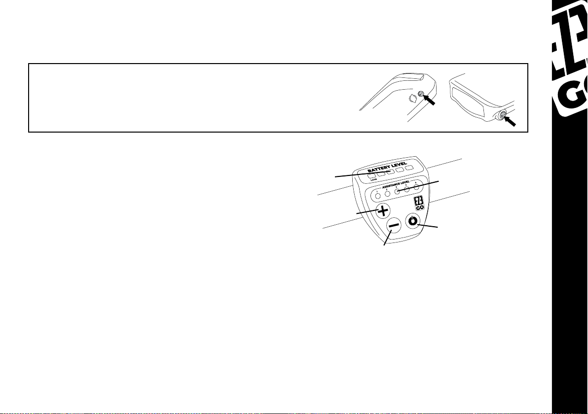
BATTERY LEVEL
INDICATOR
ASSISTANCE UP
ASSISTANCE DOWN /
WALK ASSIST
ASSISTANCE LEVEL
INDICATOR
ON/OFF
15
Page 16
Your e-bike also has a “walk-assist” function and when engaged the motor will be powered at 6km/h.
This function is designed to help in 2 ways. The rst is to assist you if you are walking with your bike and
want some help to push it along. The second is to assist you from a standing start, such as on an incline
or trafc lights. The walk assist is enabled by holding down the - button. For safety reasons, the system is
designed so that there will always be a slight delay between depressing the walk assist button and the
power assisting the motor.
Please refer to the battery section of this manual on page 49 for more information
on the electric system.
You should only charge your battery with the charger supplied or purchased from
EZEGO. Using a different charger can result in damaging the battery, or even re,
and will void your warranty.
16
Page 17
4.3. PEDAL ASSEMBLY
As previously mentioned, attaching the pedals to your e-bike needs careful attention. If the pedals
are attached onto the wrong crank arm, the crank arms can be cross-threaded and not covered by
warranty. Cross threaded crank arms will then require new expensive components to be assembled at a
competent bicycle dealer/shop.
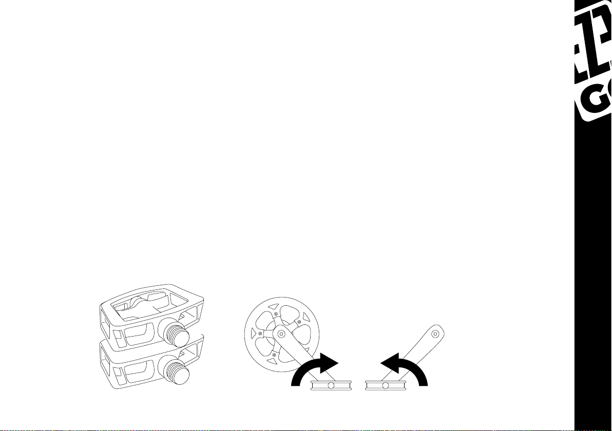
Pedals, whether they are folding or standard, are clearly marked. R = right, L = left.
An R or L sticker will be clearly shown on each pedal.
1.
In instances where the stickers have fallen off the pedals, R or L will be stamped onto the end
2.
of the axle.
As mentioned, the correct pedal needs to be attached to the correct crank arm, left pedal to the left
crank arm, right pedal to the right crank arm. If you were to sit on the e-bike in a riding position, the right
crank arm and pedal is on the right, and the left crank arm and pedal on the left.
Pedals will screw into the crank arms in the opposite directions. They are designed this way so that they
do not fall off when pedaling. The right pedal is screwed in clockwise, the left pedal is screwed in anticlockwise. Use a 15mm spanner to tighten the pedals, and always check and double check the tightness
of your pedals regularly.
RIGHT - CLOCKWISE LEFT - ANTI-CLOCKWISE
L
R
17
Page 18
4.4. FOLDING MECHANISMS
If you have purchased the EZEGO fold model you will have noticed that that are several folding
mechanisms on your electric bicycle. These folding mechanisms have been designed specically to
save space storing your e-bike and making transportation more convenient.
The 3 folding components on this model are the frame, stem, and the pedals
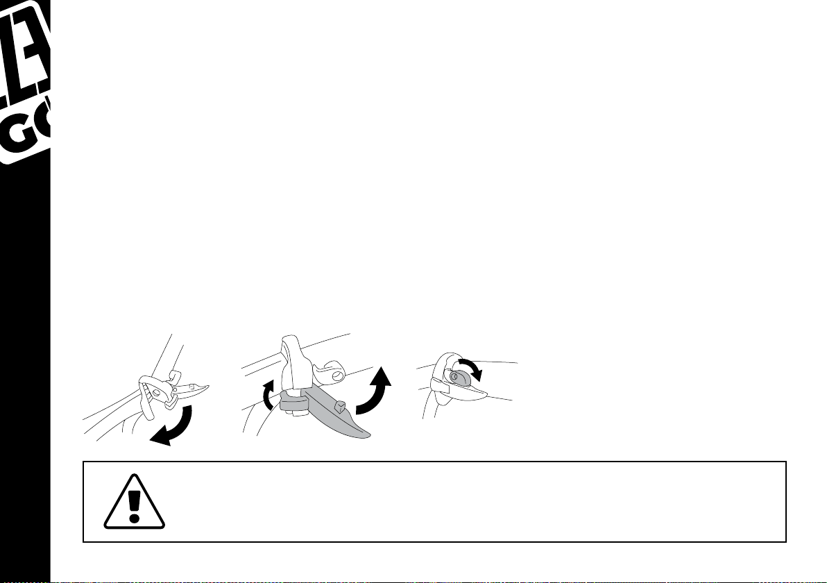
Folding Frame Mechanism:
Your frame is secured with a quick-step locking mechanism to make folding your electric bicycle as
quick and convenient as possible. You will notice rstly that your e-bike comes packaged in a folded
position. You can lock the frame in place by opening up the frame as if in a normal bicycle position (with
a wheel at the front and a wheel at the rear). Once in this position, the folding mechanism lever can
be clicked into place, and the safety hook can be positioned for added security. This process is critical
before riding your e-bike.
To re-fold the frame, simply reverse the process. Release the safety hook, grab the folding mechanism
lever and pull until the folding mechanism clicks and releases. You can now fold the frame.
18
Always make sure that the folding mechanism is locked into place, and the safety
hook secured before riding. Check and re-check that the mechanism is locked
into place. Failure to do so could result in the f rame opening whilst riding.
Page 19
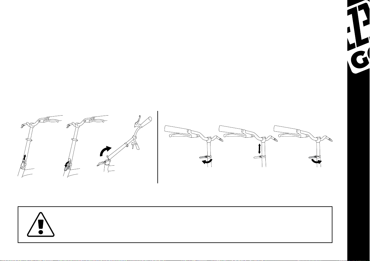
Folding Stem Mechanism:
Upon rst inspection of your EZEGO fold electric bicycle you will notice that the stem is already in a folded
position. This is the position in which you can store your e-bike, in a compact position. To assemble to its
normal position simply swing the stem upwards, and similar to the frame folding mechanism, push the
lever into place and use the safety hook for added security. This process is critical before riding your
e-bike.
You can also adjust the height of the handlebar by releasing the quick release lever and sliding to the
desired position. Once at the desired height close the quick release lever.
To reverse the process, unlock the safety hook and pull the lever until the stem is able to fold downwards.
Always make sure that the folding mechanism is locked into place, and the safety
hook secured before riding. Check and re-check that the mechanism is locked
into place. Failure to do so could result in the stem opening whilst riding.
19
Page 20
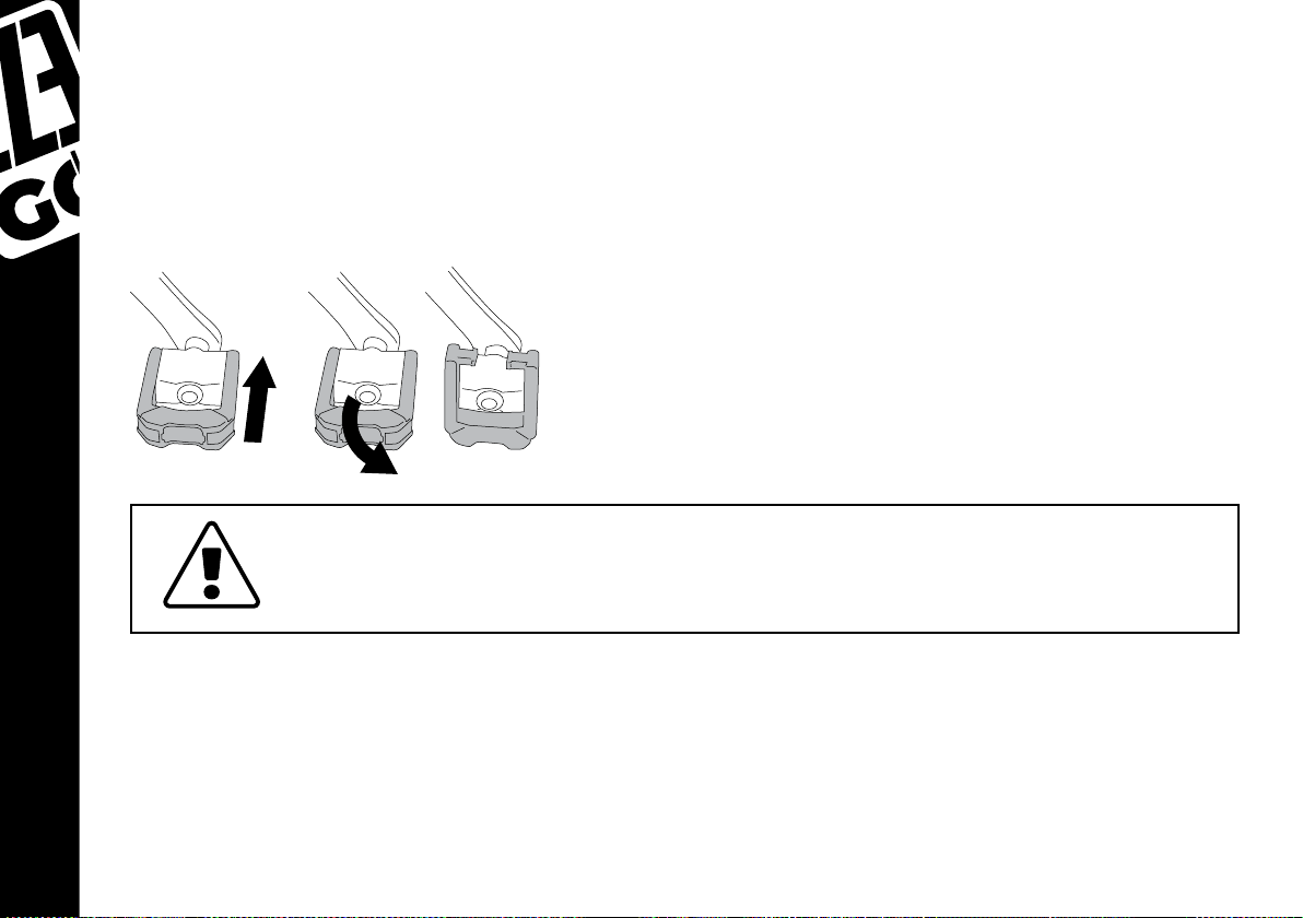
Folding Pedals:
Again, upon rst inspection of your e-bike your pedals should be in a folded position. To put your pedals
in an assembled position simply grab the crank arm with one hand, and with the other hand hold the
end of the pedal swing until the full pedal is parallel with its axle. This process is critical before riding
your e-bike.
To fold the pedal again hold the crank with one hand, push the pedal towards the crank which will
release it from its locked position. It can now be folded into a 90 degree angle, saving space for storage.
Always make sure that the pedals are locked into place before riding. Check and
re-check that the pedals are locked into place. Failure to do so could result in the
pedals slipping or folding whilst riding.
20
Page 21

4.5. HANDLEBARS AND STEMS
If you have purchased the EZEGO Step, or Commute EX models, there is some small assembly required
to setup the handlebars & stem.
The rst step is to always make sure that the forks of the e-bike are facing in a forward direction, and that
the cables are not tangled tight as a result. To conrm that the fork is facing in the correct position, the
disc brake rotor should be on the left hand side as you sit on your e-bike.
DISC ROTOR
TO LEFT
CABLES FREE
FROM TANGLES
Eze Commute Stem:
For this model, remove all 4 hex (allen) key bolts that hold the front plate onto the main part of the stem.
Once removed the handlebar can be positioned into the stem, making sure that the handlebars are the
correct way up and facing frontwards. Adjust the handlebars so that they are positioned in the middle
of the stem (there are grooves in the handlebar to help you locate the middle perfectly).
Once in position, replace the front plate in the same position as when it was removed. Insert the 4 bolts
back into the front plate and stem and begin to tighten in an X pattern (for example: top left, bottom
right, bottom left, top right). Do this in equal measures to make sure that the front plate clamps into the
stem correctly (do not tighten up one screw completely before moving on to the next).
When tightening, make sure you adjust the angle of the handlebars to suit your riding style and comfort.
21
Page 22

Once fully tight, check to make sure the gap between the front plate and the stem is even on the top
and bottom, and that the handlebars cannot be twisted or moved when attempted. For exact torque
settings for tightening these bolts, please refer to page 58 of this manual.
Always make sure that the 4 hex (allen) key bolts are tight before riding, and that
the gap between the front plate and the stem is even on the top and bottom.
It’s important to re-check before rst use, and as part of your regular e-bike
maintenance. Failure to do so could result in serious injury while riding.
Please also note that this type of stem cannot be adjusted. If you require to upgrade to an
adjustable stem, this can be purchased separately online at www.ezego.bike/accessories, and we
suggest it is tted by a qualied bicycle mechanic.
Eze Step Stem:
For this model you need to release the underside part of the stem. To do so, remove the 2 hex (allen) key
bolts that are located under the front of the stem.
Once removed, the handlebar can be positioned into the stem, making sure that the handlebars are the
correct way up and facing frontwards. Adjust the handlebars so that they are positioned in the middle
of the stem, there are grooves in the handlebar to help you locate the middle perfectly.
Once in position, replace underside part of the stem in the same position as when it was removed. Insert
22
Page 23

the 2 bolts back into position and begin to tighten in an alternate pattern (for example: tighten one bolt
a little, then move onto the other, repeat). Do this in equal measures to make sure that the underside
part clamps into the stem correctly (do not tighten up one screw completely before moving on to the
next). When tightening, make sure you adjust the angle of the handlebars to suit your riding style and
comfort.
Once fully tight, check to make sure the gap between the underside part and the main stem is even on
the both sides, and that the handlebars cannot be twisted or moved when attempted. For exact torque
settings for tightening these bolts, please refer to page 58 of this manual
Always make sure that the 2 hex (allen) key bolts are tight before riding, and that
the gap between the underside part and the main stem is even on both sides. It
is always worth a re-check. Failure to do so could result in serious injury while
riding.
23
Page 24

Eze Step Stem angle adjustment:
Simply move the safety switch downwards to the open position, and lift the folding mechanism lever
upwards to release. The stem is now free to be adjusted to your required angle. To lock the angle into
place, push the folding mechanism levers downwards until it clicks into place. Then move the safety
switch upwards into is locked position.
Always make sure that the folding mechanism is locked into place, and the
safety switch is secured before riding. Check and re-check that the mechanism is
locked into place. Failure to do so could result in the stem opening whilst riding.
24
Page 25

4.6. GEARS
Should your e-bike have any problems with the gear settings we always
recommend that they are serviced by a qualied bicycle mechanic, especially if
you are unsure about any of the following steps.
The gears setup is different depending on which model of EZEGO you have purchased. EZEGO Commute
Ex and Fold models come with a rear derailleur mechanism, whereas the EZEGO Step model is tted
with an internal hub gear system. Make sure you are comfortable with how to operate the gears before
riding on public roads.
The gears on your e-bike will be set up during production at the factory. However, due to cables stretching
slightly during the rst 100kms or so, the gears may need some slight adjustment. There should never be
any slack in the cable when set in the highest gear (read on for information about which is the highest
gear), otherwise the gears will not function properly. The gears should change and shift quietly and with
ease. If this is not the case, then they require some adjustment. Later in this section we will show you
how to make basic adjustments depending on which model of EZEGO e-bike you have purchased. If
you are unsure on how to adjust your gears, always seek help from a qualied bicycle mechanic.
Eze Commute EX and Eze Fold gear lever:
As your e-bike is tted with just a rear derailleur mechanism, you will notice that there is only one gear
shifter located on the right side handlebar. As you ride your e-bike and change the gears, the rear
derailleur mechanism will shift the chain up or down, depending on which way you shift them, on the
rear cassette cog.
The largest cog on the cassette is what we call the lowest gear and easiest to pedal. The smallest cog is
what we call the highest gear and is hardest to pedal. Low gears for hills, high gears for speed etc..
It is recommended to use a low gear when setting off from a standing start, especially if you are not
25
Page 26

using the electric system. Always make sure you
read the upcoming terrain and prepare to select
CABLE ADJUSTER
PULL TO SHIFT UP
(DOWN A COG / HARDER GEAR)
your gear to suit, as leaving it too late can cause
you to struggle to pedal, resulting in loss of speed
and potential loss of control.
Your gear shifter on your handlebar is tted with
an optical number indicator to let you know
exactly which gear you are currently in, the lower
the number, the lower your current gear.
CURRENT GEAR
INDICATOR
8
6
1
3
PUSH TO SHIFT DOWN
(UP A COG / EASIER GEAR)
With these models, you should never use the gear shifters to change gears while
the e-bike is stationary, as this will cause damage and/or alignment issues and
the gears will need re-adjusting by a qualied mechanic.
Eze Commute EX and Eze Fold rear derailleur adjustment:
If you are comfortable that you have enough knowledge to adjust the rear derailleur yourself then you
can follow these steps to help guide you. A bicycle stand is always the best way to work on your ebike, as
the rear wheel needs to be lifted in the air for this procedure.
26
Turning your e-bike upside down and resting it on the handlebars and saddle
is not recommended, as you may incur damage to the saddle and to the gear
shifters and brake levers.
Page 27

Whilst turning the pedals, shift the gear on to the
1.
highest gear (smallest cog) using the gear shifter on
the handlebar.
In this position the rear derailleur mechanism and the
2.
smallest cassette cog should line up like the diagram
below. If they do not line up, adjust the screw located
on the rear derailleur marked “H” very slightly until they
do line up. You will need to screw clockwise or anticlockwise depending on however the chain lines up.
Once point 2 is complete, change the shifter down a
3.
one position (up one cog) whilst turning the pedals, to
see if the chain moves up the cog with ease. If the chain
changes too many cogs, or does not change at all then
you need to adjust the screw for the cable tension (see
diagram). Adjust the screw in half turns whilst pedaling
until the chain is sat in the correct desired cog.
Once point 3 is complete, turn the pedals, and using
4.
the gear shifter on the handlebar, select the lowest
number (largest cog).
EZE COMMUTE REAR DERAILLEUR
‘H’ SCREW
‘L’ SCREW
CABLE TENSION
ADJUSTER
EZE FOLD REAR DERAILLEUR
‘H’ SCREW
‘L’ SCREW
Similar as point 2, check that the rear derailleur and
5.
largest cog are now lined up. If they are not aligned,
adjust the screw located on the rear derailleur marked
“L” very slightly until they are aligned without any play.
If you have any doubts about how to adjust any part of the gears, always seek
help from a serviced by a qualied bicycle mechanic.
CABLE TENSION
ADJUSTER
27
Page 28

Eze Step gears:
The rear gear section on the EZEGO Step model is assembled inside your wheel hub. It is designed this
way to require very little maintenance to it. As the gears are internal, there are no outside forces that
can cause issues with the gears, unless the e-bike is dropped or in an accident etc.. Therefore, we do not
recommend opening, and adjusting any of the rear gear properties. In general, NEXUS gears are very
reliable, and only require small maintenance every so often. Any maintenance to the NEXUS gear system
should be carried out by a qualied Shimano NEXUS bicycle mechanic.
Eze Step gear lever:
Your gear shifter is located on the right hand side of the handlebar and is tted with an optical display to
show you which number gear you are in. We refer to this kind of shifter as EZ-Fire (Easy Fire) on account
of how simple they are to use.
The uppermost shifter, closest to your brake lever, is used to shift the gears upwards to the hardest/
fastest gear (smallest cog) by pulling it towards you using your index nger. Using your index nger
will allow you to keep control of your e-bike while shifting gears, and you will nd it to be the most
comfortable and natural.
The shifter below, closest to
your body, is used to shift
the gears downwards to the
easiest/slowest gear (largest
cog) by pushing it away
from you using your thumb.
Using your thumb will allow
you to keep control of your
e-bike while shifting gears,
and you will nd it to be
the most comfortable and
natural.
CURRENT GEAR
INDICATOR
PUSH TO SHIFT UP
(HARDER GEAR)
PULL TO SHIFT DOWN
(EASIER GEAR)
28
Page 29

4.7. DISC BRAKES
All of our EZEGO electric bicycles are tted with powerful disc brake systems, as an e-bike requires a lot
more stopping power than a regular bicycle.
Get to know your brake system. In the U.K. we use the right brake
lever for the front brake, and the left brake lever for the rear brake.
It is always safer to double check which brake is which before riding
any bicycle. Simply squeeze the right brake lever, and you should
see the front caliper moving to lock onto the rotor. The same can
be done for the left brake lever and the rear caliper. You should take
some time away from public roads to get used to your brake system.
Make sure that your ngers can reach the brake levers, and can
squeeze them comfortably. If for any reason you cannot reach the
brakes comfortably, consult with your local bike shop on how the
reach of the lever can be adjusted, or even replace the levers to t
your reach.
CABLE TENSION
ADJUSTER
Applying too much power to the front brake at
high speeds can cause the rider to fall over the
front of the handlebars, or on even surfaces,
the front wheel can slide resulting in loss of
control, and the rider to fall off causing serious
injury or worse.
CABLE TENSION
ADJUSTER
CABLE
PINCH
BOLT
It should also be noted that using too much power on the rear disc
brake will force the rear wheel to lock up, causing loss of control, and
damage to the rear tyre.
BRAKE CUT OFF CABLE
(CUTS POWER TO THE MOTOR AS
SOON AS BRAKE IS APPLIED)
29
Page 30

Disc brakes basically work the same way as on a motor vehicle, but obviously a smaller scale. As you pull
the brake lever, the cable connected will pull the caliper into a closing position, which in turn creates
friction between the caliper pads and the rotor disc, slowing the e-bike.
Before riding, always check to make sure there is no grease, dirt, lubricants etc.
either on your disc rotors, or in your calipers. Failure to do so will reduce friction,
and decrease stopping power, potentially causing accident and/or serious injury.
You disc brakes are designed to control speed, not just for stopping. It is always a good idea to practice
using your brakes to slow down, and stop smoothly without locking up the wheels. Locking up is where
the wheel stops rotating, and in doing so decreases stopping force, and results in a potential loss of
control and/or serious injury. Gently squeezing the brakes and applying small amounts of pressure to
the lever progressively to come to a controlled stop is known as progressive braking. It is a good idea
to study and learn this method away from public roads until you are comfortable with the technique.
Please note, applying the brakes while the electric system is functioning will
cut all power to the motor. This is an added safety feature so that the rider is not
ghting against the power of the motor while braking. The motor will re-engage
once braking has stopped and pedalling has resumed.
30
If at any time you feel your wheel or wheels locking up, simply release the pressure a little to allow
the wheel to keep rotating, just shy of locking up. As mentioned above, practicing braking at different
speeds and surfaces will allow you to become accustomed to your e-bikes braking power. You can even
practice this technique whilst walking with your e-bike, to see exactly what pressure forces the wheels
to lock up.
Another technique to practice, especially if this is your rst time riding an e-bike, is body weight transfer,
Page 31

which can affect speed control and safe stopping. As you apply the brake or brakes, you will notice that
your body will want to continue moving forwards at the same speed travelling before applying the
brakes. This weight transfer can be very dangerous, as it can send the rider over the top of the handlebars
causing serious injury. As your body shifts weight onto a specic wheel, that wheel will require greater
braking pressure. For example, if you nd that your body weight is shifting forward when braking, try
leaning back a little, and re-distributing your weight. Shifting your weight to the back will decrease the
burden of braking force needed to be applied to the front wheel, allowing you to increase the front
brake force, and decrease the rear brake force. This is especially important if on a descent.
If you have purchased our EZEGO Step model, you will notice that this e-bike has a front suspension
fork. This makes weight transfer issues even more noticeable, as the suspension fork will dip, or contract,
as the weight compresses the fork blades. Again, we advise you to practice using your front suspension
e-bike before riding in public locations.
When riding on loose surfaces, such as gravel, or wet surfaces, greater care must be taken as stopping
distances increase dramatically. The traction in your tyres will also reduce, making cornering more
difcult, and braking less powerful, and increasing risk of wheel lock up. Always use your e-bike at
slower speeds in these type of conditions.
If you have any doubts about any parts of your braking system, you should always
seek help from a serviced by a qualied bicycle mechanic before riding again.
Disc Brake Maintenance:
As mentioned ipreviously, disc brakes work by caliper pads squeezing against the rotor. You must keep
the brakes, and especially the pads serviced regularly by a qualied bicycle mechanic.
After the rst 100kms or so of riding, the cables connecting the brake levers to the calipers may stretch
a little. This is normal. Here is a simple guide on how to adjust your disc brakes if you feel comfortable
doing so.
If you do not feel comfortable, please seek help from a qualied bicycle mechanic.
31
Page 32

Make sure that when applying pressure to the levers, the
lever should be around 30% depressed before the pads
make contact with the rotor.
When checking your disc brakes, keep the brakes open
(don’t apply pressure to the brake levers), and begin
to spin the wheel. It is important to check that while
spinning the wheel, the rotor runs freely through the
brake caliper without contact to the brake pads. Look
closely and the rotor should be centered in the caliper
between the brake pads.
If the caliper is out of position, and the rotor is touching
the pads, or not in the middle of the caliper, it can be
adjusted if you feel comfortable to do so. If you don’t feel
condent that you can adjust your brakes, take them to
a qualied bicycle mechanic.
If your brake pads are worn, they
must be replaced immediately. If
in doubt contact a qualied bicycle
mechanic.
CABLE TENSION
ADJUSTER
CABLE TENSION
ADJUSTER
ADJUSTER BOLT
Turn this to adjust
the distance from the
back brake pad to the
rotor.
32
Disc brakes can get very hot during, and after use. Never touch the rotor or pads
straight after use. These parts can also have sharp edges, so caution should be
used when handling them. Never touch the rotor or caliper while the wheel is
turning to avoid trapping your ngers.
Page 33

To clean your disc brakes we recommend using rubbing alcohol. Never use oil to clean your disc brakes
to avoid poor braking performance. After cleaning your brakes it is recommended that you ride gently
for the rst 15kms, and avoid descents and slopes during this time.
Always keep you brakes serviced by a qualied bicycle mechanic.
4.8. MUDGUARDS
Our EZEGO e-bikes are tted with a complete set of mudguards for your comfort and convenience. The
front mudguard will need installing before the front wheel is installed as it will be much easier to t.
The rear mudguards will be set up correctly in the factory and therefore should not need any adjustment.
Remove the xing bolts from the fork by turning
anti clockwise. You will need a 10mm spanner for
the crown bolt, and a 5mm allen key for the fork
legs. Be careful not to lose the washers.
Feed the mudguard through the fork legs so
that the upper xing bracket lines up with the
screw hole in the crown of the fork,
You can now replace the crown bolt,
remembering to replace the washer also. We
recommend you only t this nger tight until the
front wheel has been tted so you can ensure
the correct mudguard line.
33
Page 34

You can now attach the mudguard stays to the fork
legs by turning them clockwise using a 5mm allen
key. Remember to replace the washers also.
4.9. WHEELS
A dropout is a part of the frame or fork where the axle of
the wheel sits. Dropouts can work with all different types
of axles. EZEGO e-bikes are tted with solid axles with lock
nuts, and some models (Fold & Commute EX models) have
quick release axles (or spindles) on the forks. Instructions
for installing, removing and releasing these axles is detailed
in this section.
Hubs, and how to assemble the wheels into the dropouts:
REAR DROPOUT
EXAMPLE
(WHEEL AXEL SLOTS
IN HERE)
FRONT / FORK
DROPOUT
EXAMPLE
(WHEEL AXEL SLOTS
IN HERE)
34
Front Hub (EZE Fold & EZE Commute EX models)
For these particular models, your front hub is tted with a quick release axle. The quick release lever
mechanism clamps the wheel into place by force, pulling the lever part, and the tension adjusting nut
on the other end of the axle, together. The amount of force depends on the tension adjust nut.
Page 35

Installation and adjustment of front quick release hub
The quick release system is made up of a tension adjusting nut on one end, and a quick release lever &
saddle on the other. Next to each of these components is a small spring, which should be positioned with
the widest part of it on the outside, getting smaller towards the middle. Between all these components
is the axle (or spindle) which as attached to the quick release lever.
TENSION
ADJUSTING
NUT
SPRING
DROPOUT
HUB
DROPOUT
CLOSED
QUICK
RELEASE
LEVER
OPEN
SPRING
DISC
ROTOR
When the wheel is placed into position, the edges of the hub rests into the dropout. You will notice that
the hub is actually hollow. This is to allow the axle (or spindle) to slide through to come out the other
side. The spring and tension adjusting nut can now be screwed onto the axle. Always make sure that the
lever part of the system is on the left side of the dropout if you were sat on the e-bike (disc rotor side).
The tension adjusting nut will be on the right.
35
Page 36

By turning the tension adjusting nut clockwise, while keeping the lever from rotating, increases the
clamping force.
Turning it anti-clockwise, while keeping the lever from rotating, reduces the clamping force.
Even just half a turn of the tension adjusting nut can make the difference between safe clamping force
and unsafe clamping force. The tension adjusting nut should be tightened until it is nger tight. The
quick release lever can then be closed to secure the wheel into the dropouts.
Before nally clamping the wheel in place, make sure that the wheel is sat in the middle of the forks, and
that the brake rotor is sat inside the brake caliper. Always make sure that when the quick release lever is
in its nal position that it is pointing upwards. This is for safety to avoid anything on catching the lever,
pushing it upwards, and unlocking the wheel. To ensure your wheel is safely locked in place, when
closing the quick release lever it should leave an imprint on your palm. If this doesn’t happen,
you need to open the quick release lever, turn the tension adjusting nut clockwise, and close the
quick release lever again.
To remove the wheel simply reverse these steps.
36
Page 37

Turning your e-bike upside down and resting it on the handlebars and saddle is
not recommended, as you may incur damage to the saddle and to the gear shifters
and brake levers. We always recommend using a bike stand for maintenance
work on your e-bike.
Rear Hub (EZE Fold & EZE Commute EX models)
Installation and adjustment of rear hub motor
When inserting or removing the rear wheel, always make sure that the rear gear is set in the highest
gear (the smallest cog). Also ensure the wheel nuts are loosened enough for the axle to be able to sit in
the dropouts. You may need to remove the right hand (gear side) nut completely in order for the wheel
to pass the derailleur.
To place the wheel into position, hold the rear derailleur mechanism and push it backwards towards the
rear of the bike allowing the chain to slacken. Position the wheel so that the cassette cogs are now inside
the chain boundary. Push the wheel into the dropout, and this will start to take the slack from the chain.
Finally push it all the way into the dropouts, making sure that the brake rotor is inside the brake caliper.
When the wheel is placed into position, the axle of the hub rests in the dropout.
37
Page 38

Replace the wheel nuts onto the axle and make them nger tight against the dropout. Using an 18mm
spanner begin to tighten the nuts. Start on one side, and then move to the other, bit by bit (don’t tighten
up just one side rst fully and then the other). Finally tighten the nuts fully all the while holding the
wheel with one hand making sure that the wheel is sat in the middle of the frame, and that the brake
rotor is sat inside the brake caliper.
You can now place the cable protector over the right hand wheel nut and connect the motor to
the electric system using the quick connect cable male/female adaptors (line up the arrows on the
connectors to help you connect in the correct position).
To remove the wheel simply reverse these steps.
Turning your e-bike upside down and resting it on the handlebars and saddle is
not recommended, as you may incur damage to the saddle and to the gear shifters
and brake levers. We always recommend using a bike stand for maintenance
work on your e-bike.
38
Page 39

Front Hub (EZE Step model)
For this particular model, your front hub is the motor with solid axle, which requires the use of a 15mm
spanner. Make sure to connect the motor using the quick connect male/female adaptors.
Installation and adjustment of front hub motor
Ensure the wheel nuts are loosened enough for the axle to be able to sit in the dropouts. When the
wheel is placed into position, the axle of the hub rests into the dropouts. Replace the wheel nuts onto
the axle and make them nger tight against the dropout.
39
Page 40

Using an 18mm spanner begin to tighten the nuts. Start on one side, and then move to the other, bit by
bit (don’t tighten up just one side rst fully and then the other). Finally tighten the nuts fully all the while
holding the wheel with one hand making sure that the wheel is sat in the middle of the forks, and that
the brake rotor is sat inside the brake caliper.
Before nally clamping the wheel in place, make sure that the wheel is sat in the middle of the forks, and
that the brake rotor is sat inside the brake caliper.
You can now place the cable protector over the right hand nut and connect the motor to the electric
system using the quick connect cable male/female adaptors.
To remove the wheel simply reverse these steps.
40
4040
Turning your e-bike upside down and resting it on the handlebars and saddle is
not recommended, as you may incur damage to the saddle and to the gear shifters
and brake levers. We always recommend using a bike stand for maintenance
work on your e-bike.
Page 41

Installation and adjustment of rear Nexus hub
We wouldn’t recommend any work being carried out on these wheels unless by a fully qualied cycle
mechanic.
Should you decide to carry out your own work on a Nexus hub you may cause
damage to gears not covered by warranty, causing them to fail.
Tyre Ination
Your tyres are specically designed for the extra strength required for electric bicycles. The wall of your
tyre will tell you what PSI it should be inated to, which direction it should rotate, and it’s size, make and
model number.
Before riding always make sure that your tyres are inated to the correct PSI
stated on the wall of the tyre, that there are no bulges, and no excessive wear.
Recommended tyre and pressure/ination check should be once a week.
Inside the tyre is your inner tube, which is tted with a Presta (French style) valve. Before you are able to
inate these you will need to remove the dust cap and loosen the acorn nut. Remember to re-tighten
this and replace the dust cap when your tyre is inated or you could gradually lose air pressure.
41
4141
Page 42

Never inate the tyre higher than the PSI stated on the wall of your tyre, as they
tyre could burst, fall off the rim, leading to loss of control, resulting in a potential
accident and serious injury.
Never use a garage forecourt to inate the tyre or any other type of compressor.
Replacing a tyre
If you are not condent in the following steps, seek help from a qualied bicycle mechanic.
Remove the wheel from your e-bike using the information provided in the previous section.
1.
Disperse the air from the tube so that it is as at as possible, and remove the dust cap and
2.
securing circular bolt holding the valve in place.
Using a couple of tyre levers (easily purchased from any decent bicycle shop), prize the tyre
3.
from the rim by inserting the levers between the rim and tyre, and start sliding the tyre lever
across the rim wall.
The tyre can now be fully removed from the rim.
4.
Check to see if your new tyre has a directional pattern by looking for an arrow on the wall of the
5.
tyre. If there is an arrow, make sure your new tyre is tted in specied direction.
42
Check there is no dirt or debris inside the tyre.
6.
Insert the tube into the tyre.
7.
With a little bit of air inside the inner tube (to help it sit better), install it into the tyre with the
8.
valve coming through the valve hole. Secure the valve using the circular nut.
Page 43

Starting away from the valve, start to feed the other side of the tyre into the rim until it sits fully
9.
into the rim.
Check to make sure that the tube is not trapped, and that the tyre is sat correctly.
10.
Inate the inner tube to the instructed PSI on the wall of the tyre, and replace the dust cap.
11.
Check again that the tyre is sat correctly.
12.
Return the wheel back into position on the e-bike using the information provided in the
13.
previous section
Replacing an inner tube
If you are not condent in the following steps, seek help from a qualied bicycle mechanic.
Remove the wheel from your e-bike using the information provided in the previous section
1.
Disperse any air from the tube so that it is as at as possible, and remove the dust cap and
2.
securing circular bolt holding the valve in place.
Using a couple of tyre levers (easily purchased from any decent bicycle shop), prize the tyre
3.
from the rim by inserting the levers between the rim and tyre, and start sliding the tyre lever
across the rim wall.
Remove the inner tube from the wheel.
4.
Check there is no dirt or debris inside the tyre.
5.
With a little bit of air inside the new inner tube (to help it sit better), install it into the tyre with
6.
the valve coming through the valve hole. Secure the valve using the circular nut.
Starting away from the valve, start to feed the other side of the tyre into the rim until it sits fully
7.
into the rim.
Check to make sure that the tube is not trapped, and that the tyre is sat correctly.
8.
Inate the inner tube to the instructed PSI on the wall of the tyre, and replace the dust cap.
9.
43
Page 44

Check again that the tyre is sat correctly.
10.
Return the wheel back into position on the e-bike using the information provided earlier in this
11.
section.
It is recommended that you always carry a spare inner tube with you whenever
you are out cycling on your e-bike. Don’t rely solely on puncture repair kits as
they will only get you so far and are not a long term x.
Never use a screwdriver or any sharp objects to remove the tyre from the rim.
Tyre levers are available from any decent bicycle shop.
4.10. SADDLE AND SEATPOST
44
Previously in the manual we touched upon how it is important it is to set the correct riding position for
you.
It is important to set up your saddle height in order to avoid unnatural movements of your legs, and
more specically your knees if positioned to low. If the saddle is positioned too high, then your knees can
lock out causing pain and long term injury. In both instances, it is far more difcult to control your e-bike,
which puts you and others around you in danger.
Page 45

The following will show you how to install your saddle and seat post depending on which EZEGO model
you have.
Seat post installation (EZE Fold model)
Your Fold e-bike is equipped with a quick release seat clamp. When
in a loose position, the seat post is ready to be inserted or removed as
required. Set your saddle at the correct height for you before you start
clamping it into position.
The quick release system is made up of a tension adjusting nut on one
end, and a quick release lever on the other, integrated into a clamp that
ts over your seat tube. This is designed this way to enable you to quickly
make the e-bike compact for storage or travelling.
By turning the tension adjusting nut clockwise, while keeping the lever
from rotating, and therefore increases the clamping force.
By turning it anti-clockwise, while keeping the lever from rotating, and
reduces the clamping force.
Even just half a turn of the tension adjusting nut can make the difference
between safe clamping force and unsafe clamping force. The tension
adjusting nut should be tightened until it is nger tight. The quick
release lever can then be closed to secure the seat post into the seat
tube.
Before nally clamping the seat post in place, make sure that the saddle
is sat in line of the top tube, pointing directly at the stem.
To ensure your seat post is safely locked in place, when closing the
quick release lever it should leave an imprint on your palm. If this
doesn’t happen, you need to open the quick release lever, turn the
tension adjusting nut clockwise, and close the quick release lever
again.
To remove the seat post simply reverse these steps.
45
Page 46

When clamping the quick release mechanism shut, make sure it is as tight as
possible. Clasp your hand around the frame to get extra leverage, once the lever
is locked in place it should have left a small indentation in the palm of your hand
to make sure it is tight enough.
It is very important that you do not exceed the “minimum
insertion” mark on your seat post. When the seat post is
inserted into the seat tube part of the frame, this “minimum
insertion” mark must not be visible. Failure to follow this
warning can result in component failure, and/or loss of control
resulting in injury.
Seat post installation (EZE Commute EX and EZE Step models)
Your e-bike is equipped with a hex (allen) key seat clamp. To tighten the clamp, or loosen it off requires
a 5mm hex (allen) key. When in a loose position, the seat post is ready to be inserted or removed as
required. Set your saddle at the correct height for you before you start clamping it into position.
Before nally clamping the seat post in place, make sure that the saddle is sat in line of the top tube,
pointing directly at the stem. Always make sure that the seat post is clamped as tight as possible to
avoid accident or serious injury.
It is very important that you do not exceed the “minimum
insertion” mark on your seat post. When the seat post is
inserted into the seat tube part of the frame, this “minimum
insertion” mark must not be visible. Failure to follow this
warning can result in component failure, and/or loss of control
resulting in injury.
46
Page 47

Saddle micro-adjustments
All our EZEGO models are tted with the ability to micro adjust the saddle to get the perfect set up for
each rider. Using this adjuster enables the rider to move the saddle backwards and forwards, as well as
the angle of the saddle. It is worth noting that the angle of the saddle should be at, with the nose of the
saddle pointing directly at the handlebar stem.
It is very important that you can mount, dismount, and ride your e-bike safely, and ride in a comfortable
position whilst enabling you to access its features and safety components (such as brakes, gears and
display) without obstruction. You should adjust your saddle height in order to avoid unnatural movements
of your legs, and more specically your knees if positioned too low. If the saddle is positioned too high,
then your knees can lock out causing pain and long term injury. In both instances, it is far more difcult
to control your e-bike, which puts you and others around you in danger.
EZE Fold saddle adjustment
To adjust the saddle, unscrew the hex (allen) key bolt located on the underside of the seat post. There is
no need to screw it all the way out, just until the saddle is slightly loose. Now the saddle can be adjusted
forwards, backwards, and even the angle. Once your saddle is in the desired position, re-tighten the hex
(allen) key bolt. For NM torque tightening references, please refer to page 58 of this manual.
47
Page 48

48
EZE Commute EX and EZE Step saddle adjustment
To adjust the saddle, unscrew the hex (allen) key bolts located on the underside of the seat post. There
is no need to screw them all the way out, just until the saddle is slightly loose. Now the saddle can be
adjusted forwards, backwards.
To adjust the saddle angle, you can loosen one bolt and tighten the other. The side you loosen will tilt
down and the side you tighten will tilt up. Once your saddle is in the desired position, re-tighten the hex
(allen) key bolts. For NM torque tightening references, please refer to page 58 of this manual.
Page 49

4.11. BATTERIES
Your EZEGO battery, is the heart of your e-bike. When properly maintained, your battery should provide
you with approx. 60kms of travel. (60kms is based on an average rider weight and normal conditions /
terrain)
Your battery will arrive to you partially charged. It is recommended that you give your battery a full
charge before riding your e-bike. Your battery type depends on which EZEGO model you have.
Lithium-ion batteries can be dangerous if not looked after properly, with risk of
re or explosion.
Your battery is also equipped with a power level indicator, which will show you how much power in
increments of 25% your battery has left. All models will also indicate battery level on the handlebar
mounted display.
Switching on, and off, the Power System
For all models, you are required to switch the battery on rst. The switch is located clearly on the side of
the battery case.
49
Page 50

50
Looking after your battery properly will ensure longevity of its life, and it will continue to perform at the
levels it should.
Ensure that your battery is fully charged before rst use.
Your battery is also equipped with a “smart battery management system” which enables such features
as “sleep mode”. This feature will allow your battery to “sleep” for longer periods of time without charging.
It is always best to charge discharge and recharge your battery at least once a month, however, the sleep
mode is there as a safety feature. Charging your battery after every use will help look after your battery.
Please note, ensure that your battery is at least 50% full before allowing it to sleep
for long periods of time. We recommend that you do not allow your battery to
sleep for a period longer than 6 months, otherwise the battery cells can disperse
their energy over such time, and not be able to re-charge again.
Battery removal
EZE Fold & Step – Rear Carrier type battery
For these models, your battery is located securely inside your rear carrier and can be charged either
in this position, or with the battery removed. To remove the battery, turn the keys into the unlocked
position, and you will be able to remove your it for security. Removing the battery will leave the battery
housing and controller box in a xed position in the rear carrier. Always make sure that the battery is
fully locked back into position before using your e-bike, and make sure there are no wires or cables
protruding from the casing.
Page 51

EZE Commute EX – Downtube type battery
For these models, your battery is located securely on your down tube and can be charged either in this
position, or with the battery removed. To remove the battery, turn the keys into the unlocked position,
and you will be able to remove your battery by sliding it upwards. Removing the battery will leave the
battery housing and controller box in a xed position on the down tube. Always make sure that the
battery is fully locked back into position before using your e-bike, and make sure there are no wires or
cables protruding from the casing.
51
Page 52

Charging your battery
To re-charge your battery, make sure that the battery is switched off, plug your EZEGO charger into the
wall socket, and then connect the charger to your battery. The battery will start charging automatically so
long as there is power. A full charge should take around 5 hours. When the red light low power indicator
appears on the battery, this is the time to charge it. However, your battery has a smart management
system and therefore can be charged at any time for your convenience.
Once the charging cycle has been completed, switch off the power at the wall socket, and unplug the
charger from the battery. Your charger has a built in LED light.
When plugged into the wall, but not the battery, the charger will show a green light to signal
1.
to you that there is power to the charger.
When the charger is then connected to the battery, it will change to a red light, to signal to you
2.
that the battery is charging, and not yet full.
A green light while the charger is connected to the battery conrms that the battery is now
3.
fully powered.
Always securely fasten the rubber waterproof cap back into the charging port
after charging to avoid any water damage to the battery.
Please note, to ensure that your battery is at least 50% full before allowing it to
sleep for long periods of time. We recommend that you do not allow your battery
to sleep for a period longer than 6 months, otherwise the battery cells can disperse
their energy over such time, and not be able to re-charge again.
52
Page 53

Remember, if you are performing a long commute, take your charger with you just in case. For a better
commuting experience, a lot of users will purchase a second battery, and even a second charger to keep
in another location. Such accessories can be found in our online store at: www.ezego.bike/accessories
Battery warranty notes
Your battery & charger is covered with a 12 months warranty period, however the following points will
void this warranty:
Neglect of battery and/or charger will also void warranty, all returned batteries are tested for
1.
charging / discharging history etc..
Never stick metal or sharp objects into any of the holes on the battery, as this will damage the
2.
battery.
Only use the charger provided, or a charger provided by EZEGO to charge your battery. Any
3.
other charger will void warranty.
Never drop the battery and/or charger from a great height or hit them with extreme force.
4.
Do not allow the battery and/or charger to get wet due to risk of electric shocks or shorting out
5.
resulting in permanent damage.
Don’t allow the battery and/or charger to get close to extreme temperatures or an open ame,
6.
53
Page 54

and avoid storing it near inammable, explosive, or corrosive gas.
Never open the battery and/or charger casing or make modications. The case is sealed with
7.
a warranty sticker.
Always keep the battery and charger well ventilated while charging the battery, never cover
8.
these components while in use or hot.
Make sure that both the plugs on the charger are dry, and that they are both securely connected.
9.
Always make sure that your battery and charger are never in reach of any children.
10.
When charging, plug into the wall before plugging into the battery. When unplugging, remove
11.
from the wall plug rst before the battery. Avoid having the charger connected for longer
periods than necessary.
If you notice any abnormal behavior from the battery or the charger, switch them
off immediately, removing all plugs. This includes strange smells and overheating.
In this case, contact the store you purchased from directly.
Battery Management System (BMS) - Sleep Mode Introduction
Your EZEGO battery will rstly go into the sleep mode function when it has been resting over 2500
seconds (around 41.5 minutes). This basically means that the BMS will cut off the discharge current
automatically within the battery to just a trickle.
54
The BMS will only operate the sleep mode function when the battery hasn’t been
charged or discharged under current below 0.2Amp, which is what your EZEGO
charger is specied to.
Page 55

There are two options to wake up the battery when sleep mode has been activated under these
conditions:
Connecting the battery to the EZEGO charger.
1.
Switch the battery on by using the power button.
2.
There is also a second sleep mode function with your EZEGO battery. For safety reasons, your battery will
go into the second sleep mode function if you forget to charge it, and the battery is completely empty.
At this point, the battery voltage is lower than the discharge protection voltage, and the BMS will go into
sleep mode. This normally happens when riders have completed their journey and forget to charge the
e-bike battery.
The only option to wake up the battery when sleep mode has been activated under these conditions is
to connect it to your EZEGO charger and fully charge the battery.
This is a safety function. As with a normal battery, charging them when completely
drained is very dangerous. This function protects you and your battery. To avoid
this situation please remember to charge your battery after use.
Allowing your battery to rest in sleep mode under these conditions will eventually
terminate your battery’s life. This lifespan is approximately 6 months.
55
Page 56

4.12. DISPLAY
All EZEGO models are equipped with an LED handlebar display module. This is how the rider controls
the electric system while riding their e-bike. The module is connected to the electric system via quick
connect cable with a male / female adaptor, for easy maintenance. Always make sure this connection is
secure before switching the system on.
On the module you will see 5 power bars. These power bars tell you exactly how much power your
battery has, in increments of 20%. Power levels go from left to right, as you can see the left side of these
power bars is marked “low”.
There are also 5 LED lights marked 1,2,3,4,5 from left to right. This tells the rider what level of power assist
they are in, 1 being low power assist, and 5 being high power assist. High power assist will supply the
most power while you pedal.
The last 3 buttons located on the module are:
The power button, for switching the
1.
module and electric system on and
off (except the battery, that battery
has its own switch).
“+” button, which is used to shift up
2.
the power assist level. This button will
also engage the 6km/h walk assist
mode when depressed.
“-“ button, which is used to shift down
3.
the power assist level.
BATTERY LEVEL
INDICATOR
ASSISTANCE UP
ASSISTANCE DOWN /
WALK ASSIST
ASSISTANCE LEVEL
INDICATOR
ON/OFF
56
For all the other electrical components, they should be left to a qualied electric bicycle mechanic
should you encounter any issues.
Page 57

4.13. READY TO RIDE! - FINAL INSPECTION
Please make sure you check and understand the points below, just to double conrm that your e-bike
is ready for its rst ride:
The electric bicycle is fully assembled, and there are no components left in the carton, only
1.
packaging products. Don’t forget to keep the packaging until your warranty period has passed.
The chain is lubricated well.
2.
All xings, including the wheel xings, are tted as instructed and tight.
3.
Wheels are running true, and the tyre pressure is as stated on the tyre wall.
4.
Saddle is correct height and comfortable for the rider, and not beyond the minimum insertion
5.
mark.
Handlebar is comfortable to your riding position.
6.
Brakes are setup and functioning properly as instructed, and the rider is able to reach the
7.
brake levers comfortably.
Gear are setup and functioning properly as instructed, and the rider is able to work the gear
8.
shifter comfortably.
57
Page 58

4.14. TORQUE SPECIFICATIONS
When tightening up the bolts and screws on your e-bike, it is highly recommended that you follow the below guide.
This conrms what each screw or bolt for each component on the electric bike must be tightened up to in Newton
Metres (Nm). This is why we always recommend you using a qualied bicycle mechanic.
If the screws are too loose they can fatigue more easily and move around. If too tight they can become distorted
and stretch.
A mistake can result in a failure to the component which would result in an accident and/or serious injury. Torque
wrenches are available at a good bicycle shop, or a car accessory store. Always follow the guidelines and instructions.
58
Threaded Headset Locknut
Stem Expander Bolt (quill type)
Handlebar Binder Bolt (quill type)
Stem Binder Bolt (threadless)
Compression Cap
Stem Faceplate Bolts
Pedal
Crank Arm
Axle Nut
Seat Post Binder
Seat Rail Binder
Shift Lever
Rear Derailleur Mounting Bolt
Rear Derailleur Cable Pinch Bolt
Rear Derailleur Pulley Wheel Bolt
Disc Brake Rotor To Hub
Disc Brake Caliper Mount
16-24 Nm (142-212in-lb)
17-22 Nm (150-195in-lb)
17-22 Nm (150-195in-lb)
13.5-16 Nm (120-144in-lb)
2-3 Nm (20-26in-lb)
13.5-19 Nm (120-168in-lb)
34.5-40 Nm (307-354in-lb)
45-50Nm (398-442in-lb)
30-42 Nm (260-372in-lb)
4-6.5 Nm (36-60in-lb)
18-34 Nm (160-300in-lb)
6-8 Nm (53-70in-lb)
8-10 Nm (70-86in-lb)
4-5 Nm (35-45in-lb)
3-4 Nm (27-36in-lb)
4-7 Nm (36-60in-lb)
6-9 Nm (52-84in-lb)
Brake Caliper Mount to Frame (side/dual)
Brake Caliper Mount to Braze-on Linear Pull/
Cantilever
Brake Pad (Threaded Stud, Dual Pivot/Sidepull)
Brake Pad (Smooth Stud, )
Brake Cable Pinch Bolt (Linear Pull)
Brake Cable Pinch Bolt (Sidepull/ Dual Pivot)
Brake Caliper Arm Pivot (Dual Pivot)
Sidepull/Dual Pivot Brake Pad Bolt
Cantilever Straddle Wire Pinch 5 x 0.8 Thread
Brake Caliper Wire Pinch Linear Pull
Brake Lever (MTB type)
Brake Lever (Drop Bar Type)
Mudguard Bolts 6-9 Nm (53-78in-lb)
Mudguard Bracket Bolts 2.5-4 Nm (25-35in-lb)
Base Clip Bolts
Mount Bracket Bolts
Strut Bolts
8-9.5 Nm (70-85in-lb)
5-7 Nm (44-60in-lb)
5-7 Nm (44-60in-lb)
8-9 Nm (70-78in-lb)
6-8 Nm (53-69in-lb)
6-8 Nm (53-69in-lb)
8-9.5 Nm (70-85in-lb)
5-7 Nm (44-60in-lb)
4-5 Nm (35-43in-lb)
5.5-8.5 Nm (50-75in-lb)
6-8 Nm (53-69in-lb)
6-8 Nm (53-69in-lb)
6-9 Nm (53-78in-lb)
2.5-4 Nm (25-35in-lb)
2.5-4 Nm (25-35ft-lb)
2.5-4 Nm (25-35ft-lb)
2.5-4 Nm (25-35ft-lb)
Page 59

4.15. MAINTENANCE OF YOUR INVESTMENT
As you use your electric bicycle, be sure to keep it well cleaned and maintained. Here are some tips to help look after
your new investment.
Try to avoid puddles, and be careful on damp roads for potholes. Water and the electric system
1.
will not mix, and will more than likely end up failing.
Keep your electric bicycle in shelter, and avoid rain at all costs.
2.
Riding around coastal areas exposes your e-bike to salt which is very corrosive to the majority
3.
of the components on your e-bike. Take care in these areas and carefully clean your e-bike after
use.
Clean your e-bike regularly.
4.
If you are caught in the rain, clean you e-bike once you are home. You can also anti-rust
5.
treatment, and touch-up paint on any chips or scratches you pick up over the years to protect
any areas without their protective paint coat. Clear nail polish is also a secret tip for covering
these areas after touch-up paint has been applied.
Keep your components, especially your drive / gear system well lubricated. Keep lubrication
6.
away from the disc rotors and calipers.
Before lubrication, always wash off dirt and muck before application.
7.
Be careful of over-lubrication, wipe off any excess with an old cloth.
8.
It is also worth reminding you that components such as gear & brake cables, and spokes take a little time to bed in,
and therefore cables may stretch etc.. We recommend taking your electric bicycle for a checkup after one month of
riding, or 20 hours, just to make sure everything is working as it should be.
59
Page 60

Below is a guideline for what components you should be looking at and approximately how often you should do so.
After every long or hard ride, or after every 10 to 20 hours of riding, check the following:
Squeeze the front brake and rock the bike forward and back. Everything feel solid? If you feel a
1.
clunk with each forward or backward movement of the bike, you probably have a loose headset.
Lift the front wheel off the ground and swing it from side to side. Feel smooth? If you feel any
2.
binding or roughness in the steering, you may have a tight headset.
Grab one pedal and rock it toward and away from the centerline of the bike. Then do the same
3.
with the other pedal. Anything feel loose? If so, have a qualied bicycle mechanic check it.
Take a look at the brake pads. Starting to look worn or not hitting the wheel rim squarely? They
4.
may need adjusting or repairing, see the brakes section of this manual.
Carefully check the control cables and cable housings. Any rust? Kinks? Fraying? If so, have a
5.
qualied bicycle mechanic replace them.
Squeeze each adjoining pair of spokes on either side of each wheel between your thumb and
6.
index nger. Do they all feel about the same? If any feel loose, have the wheel checked for
tension and trueness.
Check the tyres for excess wear, cuts or bruises.
7.
Check the wheel rims for excess wear, dings, dents and scratches. If present, ask a qualied
8.
bicycle mechanic if they need replacing.
Check to make sure that all parts and accessories are still secure, and tighten any which are
9.
not.
60
Check the frame (particularly in the area around all tube joints), handlebars, stem, and the seat
10.
post for any deep scratches, cracks or discoloration. These are signs of stress-caused fatigue,
and indicate that a part is at the end of its useful life and needs to be replaced
Page 61

As required:
If either brake fails, don’t ride the e-bike. Have your local bicycle mechanic check the brakes.
1.
If the chain won’t shift smoothly and quietly from gear to gear, the derailleur is out of adjustment,
2.
take it to a qualied bicycle mechanic.
It is recommended that every 25 (hard off-road) to 50 (on-road) hours of riding, take your e-bike
3.
to a qualied bicycle mechanic for a complete checkup.
6 Week Inspection
It is recommended that after this period you should inspect your e-bike, as things will slacken off and need retightening.
Every 6 Months
It is recommended that every 6 months you complete a full service on your e-Bike to keep it in excellent working
condition.
Periodically check the wiring and connectors to ensure there is no damage, and that the connectors have good
continuity.
Caring for your Battery
Properly maintain the batteries by keeping them fully charged when not in use. When stored and not in use, please
remove the battery and store in a cool dry place, charging periodically, if your battery is not tted with SLEEP MODE
function, as the battery will discharge over time of none use. It is recommended that the battery is charged AT
LEAST once a month while it is not being used.
Failure to do this will result in the battery falling into a dormant state, rendering the battery unrepairable.
Please Note: It is ok to oil the chain and front or rear axle (depending if you have front or rear hub motor), but THE
MOTOR SHOULD NOT BE LUBRICATED.
If you have an accident
First, check yourself for injuries, and take care of them as best you can. Seek medical help if necessary.
Next, check your e-bike for damage. After any crash, take your bike to your local mechanic for a thorough check.
Carbon composite components, including fames, wheels, handlebars, stems, crank sets, brakes, etc., which have
sustained an impact must not be ridden, until they have been disassembled, and thoroughly inspected by a
qualied mechanic.
61
Page 62

5. WARRANTY
Subject to the following provisions, Pennine Sports Limited, warrants that the goods will correspond with their
specication at the time of purchase, and will be free from defects, in materials, and in workmanship.
Pennine Sports Limited offers a 10 year warranty on steel frames, and 1 year on aluminium frames, for any problems
relating to manufacturer workmanship, or arising from the material defects, including breakages, or cracking
caused while riding (other than rider misuse).
All other components are guaranteed for 12 months, for problems related to manufacturer workmanship, or arising
from material defects, with the exception of consumable components, for example: brake blocks, brake pads, tyres
and inner tubes.
Pennine Sports Limited offers this warranty to the original purchaser of the product. This warranty is not transferable
to a third party.
Transport and labour charges in relation to warranty supplied parts are not subject to the terms of this guarantee,
and shall be the responsibility of the owner.
The original bill of sale, or proof of purchase, must be presented to the approved dealer, prior to obtaining warranty
services.
The above guarantee is in addition to your statutory rights.
Please Note: This guarantee does not cover failure experienced during activities such as any form of jump,
stunt, wheelies, race/competition or other extreme riding of any kind, and will invalidate your warranty.
If the bike has been used for rental use this will result in invalidating the warranty. Poor maintenance, or
modications that no longer comply with regulations or original specications, will also invalidate the
warranty.
62
Page 63

Customer Services: 01484 506 123
visit ezego.bike for more products and accessories
63
Page 64

visit ezego.bike for more
products and accessories
EZEGO e-bikes and accessories are imported to the
UK exclusively by Pennine Sports Ltd.
www.penninesports.com
 Loading...