

Page 1

DDVVRR OOppeerraattiioonn MMaannuuaall
DII
D
VII
V
PPCC--bbaasseedd DDVVRR SSyysstteem
6644cchh// 4488cchh// 3322cchh// 1166cchh// 88cchh// 44cchh
GII
G
D
E
D
E
T
ALL
T
A
O
O
R
E
C
R
E
ver. 7.0.1.0
Feb. 25, 2009
C
O
O
R
R
D
D
E
R
E
R
mss
Page 2

DDVVRR OOppeerraattiioonn M
Maannuuaall
Table of contents
■ Chapter 1: System Overview…….……………………………...…..………………………………….. 4
1.1 Description …………………………………………………………………………………………. 5
1.2 Main Functions …………………………………………………………………………………….. 5
1.3 System View ………………………………………………………..…………………..…………… 8
1.4 Connecting Control Outputs, Sensor Output…………………………………………….………… 9
1.5 Connection with PTZ …………………………..………………….……………………………….. 9
■ Chapter 2: Monitoring Mode……………………………………….………………………………………. 10
2. Monitoring Mode Overview ………………………………………………………….……………... 11
2.1 Quick Play ….………………………………………………….………………………………….. 12
2.2 Monitoring Menu ……………………………………………….………………………………….. 13
2.2.1 Camera View ……………………………………………………………………….. 12
2.2.2 Audio Volume Control ……….…………………………………………………….. 13
2.2.3 Switching Camera Position …………….………………………………………….. 13
2.2.4 Recovering Camera Position …………………….……………………………….. 13
2.2.5 Screen Division Buttons …………………………………………………………… 14
2.2.6 Screen Auto-Switching ……………………………..……………………………….. 14
■ Chapter 3: Setup Mode…….………………………………………..……………………………………… 15
3. Setup Mode Overview… ………………………………………………….……………………... 16
3.1 Camera Setup …………………………….………………………………………………………. 17
3.1.1 Link to Sensor ……………….………………………………………………………… 17
3.1.2 Link to Control ………………………………….……………………………………… 17
3.1.3 Full Screen Setup …………………………….……………………………………… 17
3.1.4 PTZ Protocol Setup …………………...……………………………………………… 18
3.1.5 Default Camera Setup …………………….….………………………………………. 18
3.2 Recording Frame Setup ……………………….………………………………………………… 19
3.2.1 Intensive Recording Setting ..………………..……………………………………… 20
3.2.2 Regular Interval Recording Setting .………………….……………………………… 20
3.2.3 Video Loss Setting ..……………………………..…………………………………… 20
3.2.4 TV Out Setting ..…………………………………..…………………………………… 21
3.3 Recording Schedule ……………………………………………………………………………... 22
3.4 Special Day Recording Setup ………………………………………………….………………... 23
3.5 Motion Setup …………………….……………….…….………………………………………… 24
3.6 Sensor Setup …………………….………………….….………………………………………… 25
3.7 Control Setup …………………….……………….…….………………………………………… 25
3.8 User Registration ………………….……………….…….………………………………………… 26
3.8.1 User Add/Edit ……………...…………………..……………………………………… 26
3.9 System Setup ……………..………………….…………………………………………………… 27
3.9.1 Disk Management ………...…………………..……………………………………… 28
3.9.2 E-mail Setup …..………………………….…..……………………………………… 28
3.10 Network Setup ………..………..…………….…………………………………………………… 29
3.10.1 DDNS Setup ……………...………………………………………………………… 29
3.10.2 Network Setup ………………………………..……………………………………… 31
3.11 Log Information ……………..…………………………………………........................................ 32
- 2 -
Page 3

■ Chapter 4: Search Mode ………………………………….………………………………………………... 33
4.1 Overview…………………………………………………………………………………………….. 34
4.1.1 Select Date and Time ………………………………………………..………………. 35
4.1.2 Play Control Buttons ……………..…………………………………………………. 35
4.1.3 Speed Options ….………………………………….………………………………….. 35
4.1.4 De-interlacing Filter …………………………………………………………………….. 36
4.1.5 Camera Enable and Selection ……………………………………………………….. 36
4.1.6 Screen Division Buttons ……………………………………………………………….. 36
4.1.7 Audio Volume Control ………………………………………………………………….. 37
4.2 Preview (Thumbnail Panorama) Search ……………………………………………….……….. 38
4.3 Event Search …………..…….……………….…………………………………………………….. 39
4.4 Object Search ………..…….……………….…………………………………………………….. 40
4.5 Recording Status Table ……..……………………………………………….…………………… 41
4.6 Goto Search …….. …………………………………………………………….…………………… 41
4.7 Backup Play …………………….……………………………………………..…………...……… 42
4.8 Saving Images to JPG, AVI, EXE (MPEG-4) File ...……………………………………..…….. 43
4.9 Printing Images ………………….………………………………..……………………………….. 44
■ Chapter 5: Backup …….…………..…………………..……………………………………………………… 45
■ Chapter 6: Pan/Tilt/Zoom Control …….………………………………………………….……..………… 48
6.1 PTZ Control Overview ………………….……………..…………………………………………. 49
6.2 PTZ Camera Setup …………………………….…………………………………………………… 49
6.3 PTZ Options ………………….…………………………………..…………………………………. 50
6.4 Preset link with Sensor Alarm .………………………………………………..…………………. 52
■ Chapter 7: (Remote) Client Program …………………………………….………………..……………… 53
7.1 NetDVR Program ……………………………………………………………..……………….….. 54
7.1.1 Program Installation …………..……………………………………………………… 54
7.1.2 Monitoring Mode ………..……………………………………………………………... 55
7.1.3 Connection to NVR ……..…………………………………………………………… 56
7.2 Web Browser Connection ………………………………………………………..…………….. 57
7.2.1 Connection & Monitoring Web Client ……………………………………………… 57
■ Chapter 8: CMS (Central Monitoring System) …………………………………….…………. 58
8.1 CMS Installation ……………..………………………………………………..…………………. 59
8.2 CMS Windows ….…………………………………………………..………..…………………. 59
8.3 CMS Start ………………..……………………………………………………………………….. 60
Group/Site Add ……..…………………..………………………………..………………. 60
Connect to the Site …………………………..………………………………….……………. 61
Activate Site Menu (Setup, Search, Backup) ………………………………….……………. 61
8.4 CMS Menu …. ……………………………………….……….……………………………………. 61
8.4.1 PTZ Control ……..…………………..………………………………..………………. 61
8.4.2 Event & Log List ……………………..………………………………..………………. 62
8.4.3 CMS Setup …………………………..………………………………..………………. 63
Option Registration
CMS User Registration
CMS Version Information
8.4.4 Healthy List …………………………..………………………………..………………. 64
8.5 E-MAP Program ….………………………………….……….……………………………………. 65
8.5.1 CMS MAP Installation …………………………..……………………………………. 65
8.5.2 CMS MAP Edit ……..…………………………..……………………………………. 65
8.5.3 Camera Icon Add on MAP Image ……..………………………..…………………. 67
8.5.4 Camera Integration with Icon on Map …………………………..…………………. 68
- 3 -
Page 4

r
Chapte
1
System Overview
1.1 Description
1.2 Main Functions
1.3 System View
1.4 Connecting Control Output, Sensor Output
1.5 Connection with PTZ
- 4 -
Page 5
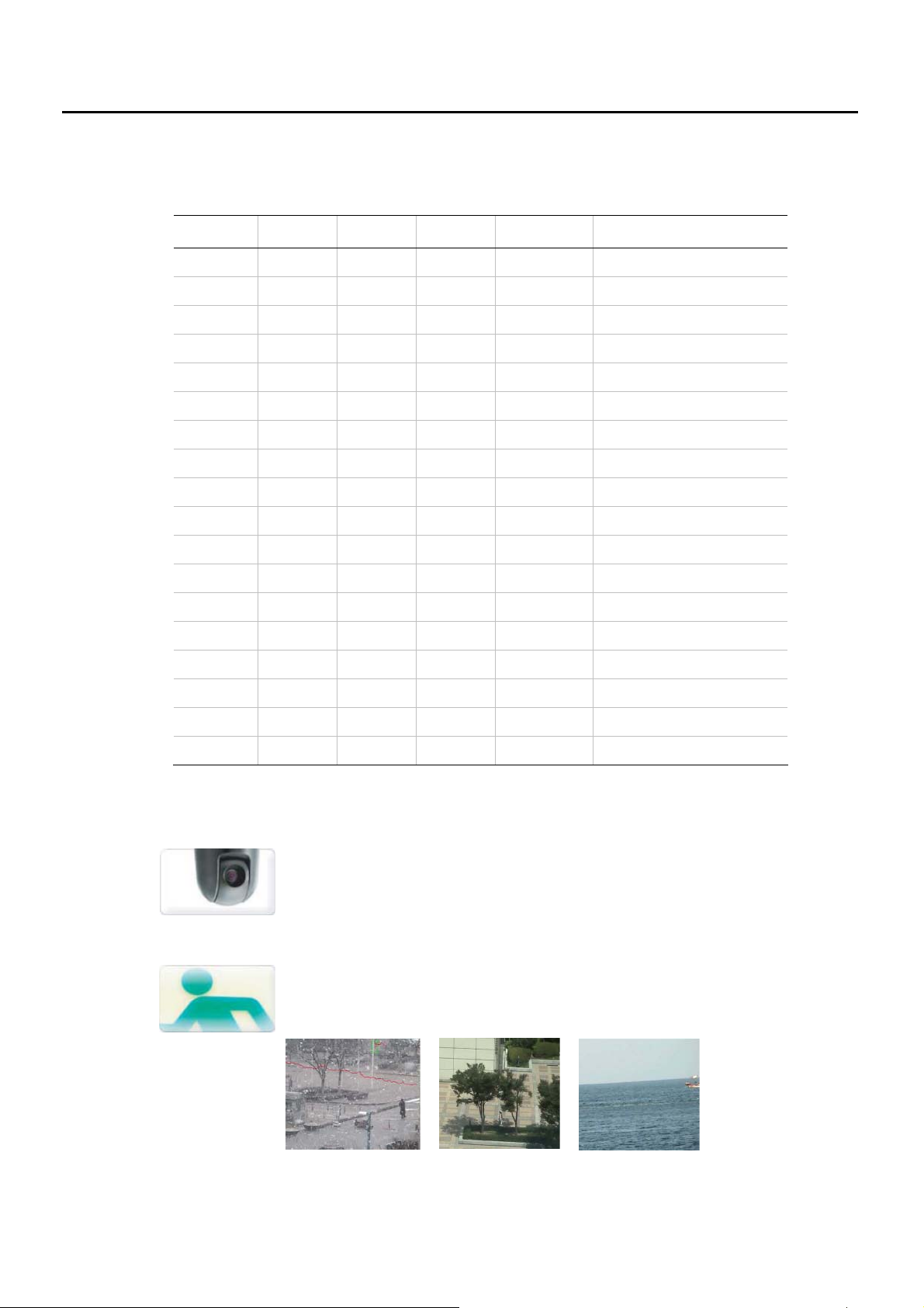
1.1 Description
Model Number of PC-based DVR
Model No.
6496
Video
Input
64 ch 16 ch* 32 x 2 Real Time 480fps @ CIF
Audio
Input
Screen
(max)
Display
Speed
Max. Recording Speed
3296
6448
4848
3248
1648
1624
1612
0824
0812
1216
1208
1204
6016
3004
1648 H/C
0824 H/C
32 ch 16 ch* 32
64 ch 16 ch* 16 x 4
48 ch 16 ch* 16 x 3
32 ch 16 ch* 16 x 2
16 ch 16 ch* 16
16 ch 16 ch* 16
16 ch 16 ch* 16
8 ch 8 ch 8
8 ch 8 ch 8
16 ch 4 ch 16
8 ch “ 8
4 ch “ 4
16ch “ 16
4 ch 1ch 4
16 ch 16ch 16
8 ch 8 ch 8
“
“
“
“
“
“
“
“
“
120fps
120fps
Real Time
60fps
30fps
Real Time
“
“
“
“
“
“
240fps @ HD1, CIF
120fps @ D1, HD1, CIF
240fps @ HD1, CIF
120fps @ D1, HD1, CIF
120fps @ HD1, CIF
“
60fps @ HD1, CIF
30fps @ HD1, CIF
480fps @ D1 (h/w codec)
240fps @ D1 (h/w codec)
“
0412
* = Optional
4 ch 1ch 4
1.2 Main Functions
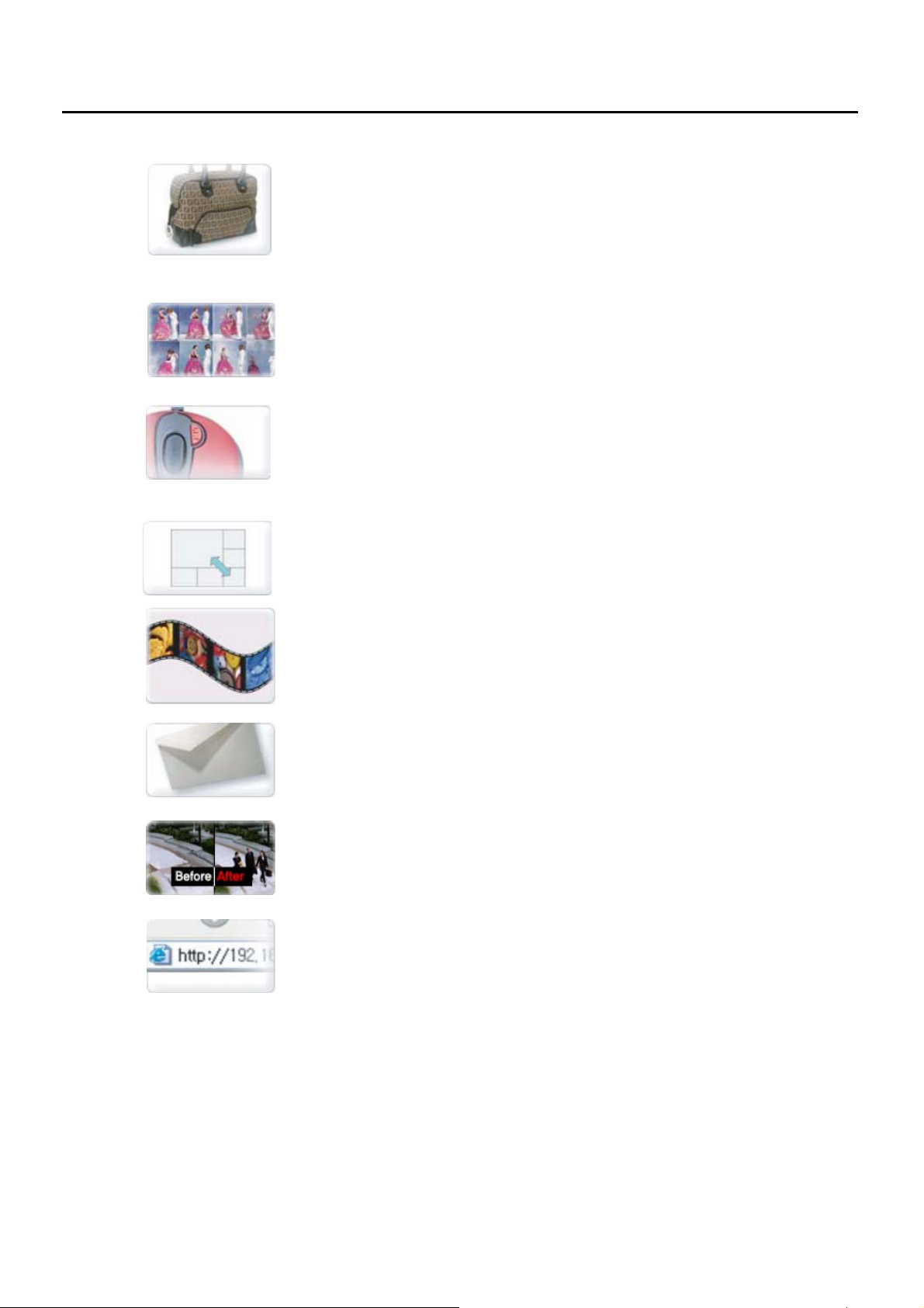
Auto Motion Tracking
Make PTZ camera to follow moving object automatically
(refer to Chapter 3.5 Motion Setup for details)
Intelligent Motion Detection
Save HDD storage by recording just when there is any real movement. Natural changes
like light, wind, water wave can be ignored
(SNOW) (Moving Trees) (Wave)
“
120fps @ D1 (s/w codec)
- 5 -
Page 6
Missing Objects Search
During playback, you can search data again which has changes in the area you defined
Can be used when you want to find out time of the missing objects and so on.
(refer to Chapter 4.4 Object Search)
Thumbnail (Panorama) Preview Search
Thumbnail (Panorama) Preview of recorded data per hour, min before playback
(refer to Chapter 4.2 Preview Panorama Search)
One-Click Camera ZOOM-IN
One-click Full Screen or Zoom-In PTZ Camera just by clicking Mouse on Camera
Window
Camera Window Position Change
Dragging Mouse, you can exchange positions of Camera Windows.
Backup to various Format (JPG, AVI, EXE)
Copy recorded data of a certain camera at a certain time as snapshot (JPG) or Mobile
Images as AVI or EXE file. (refer to Chapter 4.8 Saving Images as JPG, AVI, EXE)
Automatic Email Transmission
When a event occurs, its images can be sent to the email address automatically
(refer to Chapter 3.9.2 E-mail Setup)
Pre/Post Alarm Recording
Before/After events can be recorded as well (refer to 3.2 Recording Frame Setup)
Web Brower Client
Just by input of IP address of the unit on the Explorer, you can control units from remote
place (refer to Chapter 7.2 Web Brower Client)
- 6 -
Page 7
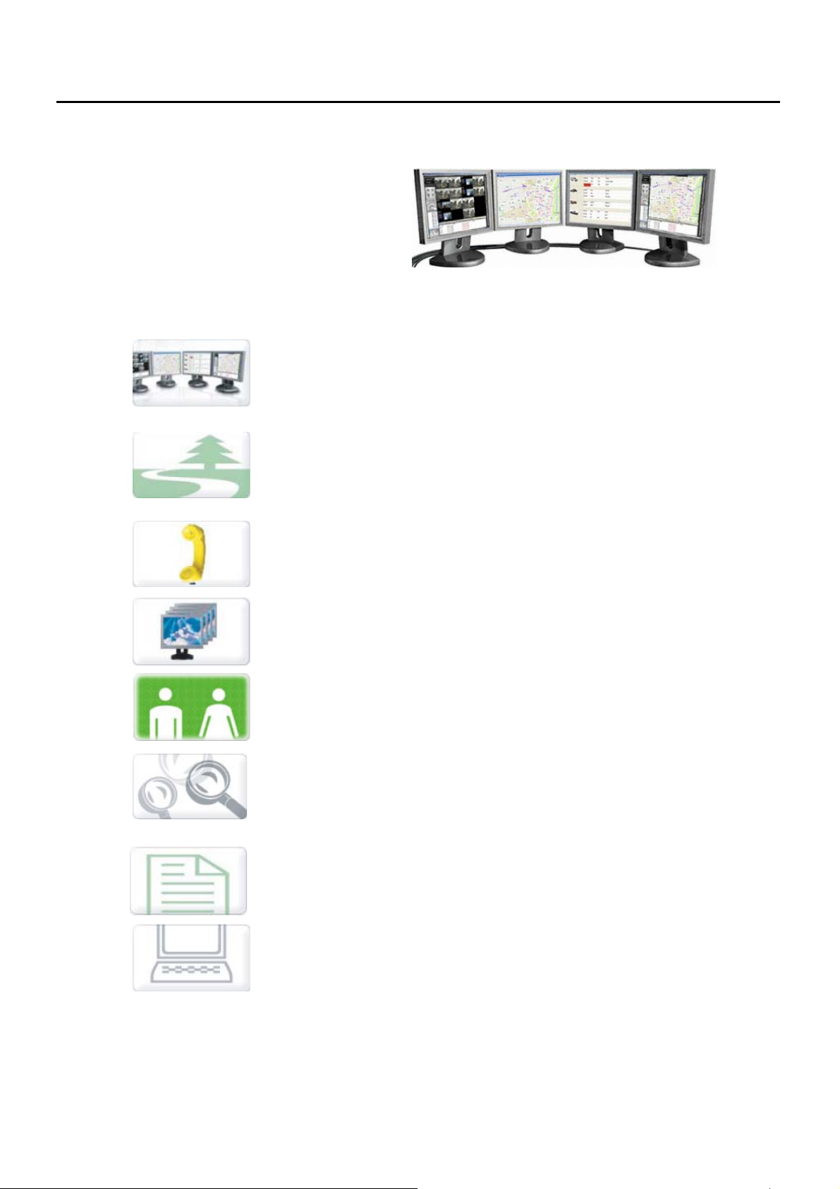
Central Monitoring System (CMS)
Analogue Cameras and IP Network Cameras can be monitored and controlled using just one CMS which
provided free of charge with our NVR, PC-DVR and Hybrid DVR
Multiple Monitor Support
CMS system support max. 4 Monitors
E-MAP Program separately configured
Free E-MAP program is supplied where you can view or control Camera on MAP which
can run on separate monitors with CMS (refer to Chapter 8.5 E-MAP)
2-Way Audio Communication
Users at CMS can communicate with users at units (refer to 8.2 CMS Window)
No Limit in Site Registration
NVR, DVR can be registered without its limit (refer to 8.3 CMS Start)
Different User Authorization
Make Users ID with different authorities each (refer to Chapter 8.4.3 CMS Setup)
Various Search Modes
Can search recorded data of NVR, DVR with various mode
(refer to 8.3 CMS Start – Site Menu or Chapter 4 SEARCH MODE)
Site Status Check
List up of registered NVR, DVR Status (refer to Chapter 8.4.4 Healthy List)
Remote Setup
Can setup, search and backup data of NVR, DVR from remote places
(refer to Chapter 8.3 CMS Start, Connect Menu)
- 7 -
Page 8
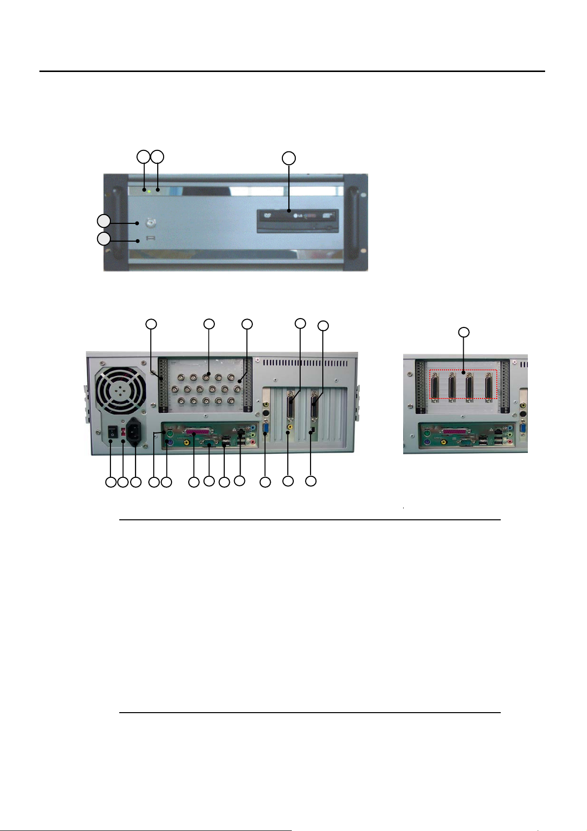
1.3 System View
■ Front View
1
2
3 4
5
1. Power Switch (with Key)
2. USB Port
3. Power LED
4. HDD LED
5. CD/DVD RW
■ Rear View of 16ch, 8ch, 4ch DVR 32ch, 48ch, 64ch
1. Sensor Inputs
2. Camera Inputs
(in case of 32~64ch models, Octopus Cables are connected)
3. Control Alarm Outputs
4. Octopus Cable Connector for 16 channels Looping-Out
5. Octopus Cable Connector for 16 channels Audio Input
6. Power On/Off Switch
7. 110V / 220V Switch
8. AC Power Input
9. PS/2 Mouse Input
10. PS/2 Keyboard Input
11. LPT Parallel Printer Port
12. DB-9 (RS-232) Serial Port
13. USB Ports
14. RJ-45 Network Jack
15. DB-15 SD VGA Monitor Output
16. RCA TV Output (Composite)
17. RS-422 Interface (for connection with PTZ camera or Receiver)
- 8 -
Page 9
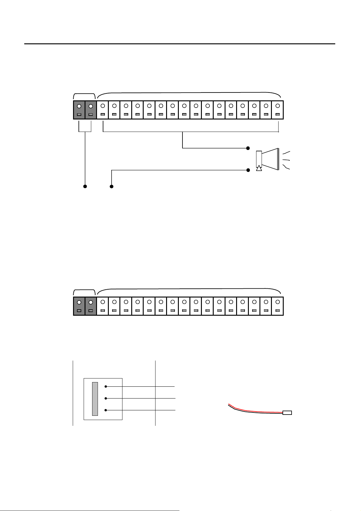
1.4 Connecting Control Outputs (Digital Outputs)
COM Control Output (#1~#16, the top one is #1)
( - ) ( + )
External Power Supply (DC 12V) Siren, Alarm, Outside Relay
Control Outputs can be automatically activated by Motion or Sensor Detections.
(To adjust these settings, please refer to the Section 3.2.4)
Only 12V (300mA) voltage and smaller is supported. When controlling devices require more voltage than
12V, use an external Outside Relay control that supports higher voltages.
Connecting Sensor Inputs
COM Sensor Input (#1~#16, the top one is #1)
Connect one signal line to the common port and connect another signal line to the desired sensor number.
(To adjust the type of sensor (NC, NO), see Section 3.1.1)
1.5 Connection with PTZ
RS-485/ 422 Input
RS-485/ 422 Adapters
□
□
□
Signal Line (+)
Ground
Signal Line (-)
- 9 -
Page 10

r
Monitoring Mode
2. Monitoring Mode Overview
2.1 Quick Play
2.2 Monitoring Menu
2.2.1 Camera View
2.2.2 Audio Volume Control
2.2.3 Switching Camera Position
2.2.4 Recovering Camera Position
2.2.5 Screen Division Buttons
2.2.6 Screen Auto-Switching
Chapte
2
- 10 -
Page 11
0
A
2
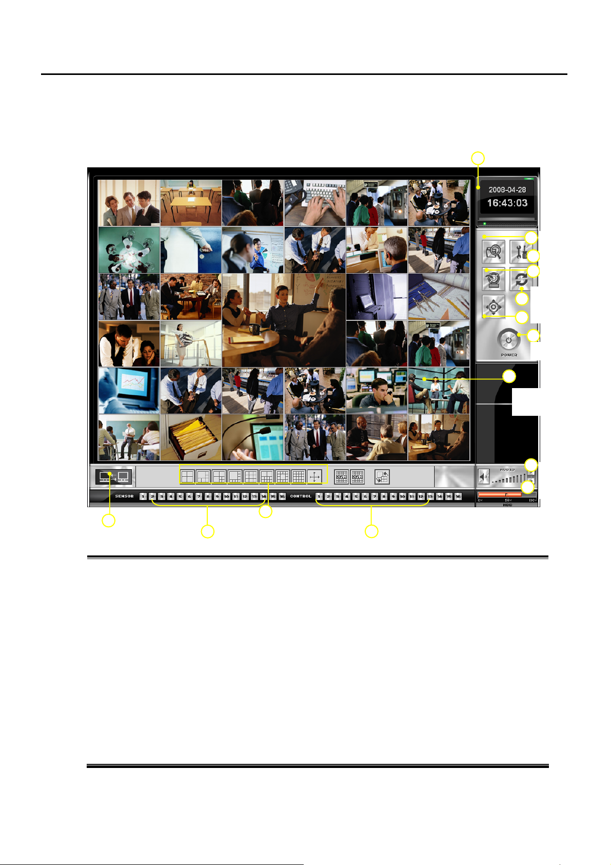
2 Monitoring Mode Overview
Turn the system power ON, and then the Main Monitoring screen appears as default.
14
13
Sensor
1. Date and Time Indicator – Displays current date and time
2. Search – Go into SEARCH mode to playback, copy the recorded data
3. Setup – Camera Setup, Recording Frame, Recording Schedule, System Setup, etc.
4. Backup – Manual Backup options.
5. Auto Switching – Divided screens can be switched automatically in sequential order.
6. PTZ Control – controls Pan, Tilt, and Zoom functions.
7. Exit – for Log off, Power off, Reboot and Quit Program options.
8. Quick Play – execute Quick Play Mode by right click Mouse at a Camera
9. Audio Volume Control – Turn On/Off Audio as well as adjusts Volume.
10. HDD Storage Indicator – Displays percentage of free space for each partition being used.
11. Control Output Status – Turn On/Off the connected Output Relays
12. Screen Division – allow you to view one or more sets of cameras at a time
13. Sensor Status Display – displays the status of each Sensor connected
14. Network Status – blink in Orange color when a client is connected to this system
1
Control Network Screen
11
1
Date / Time
8
2
Search
3
Setup
4
Backup
Switching
5
PTZ
6
7
Power
Quick Play
(right click)
9
udio
1
HDD
- 11 -
Page 12
2.1 Quick Play
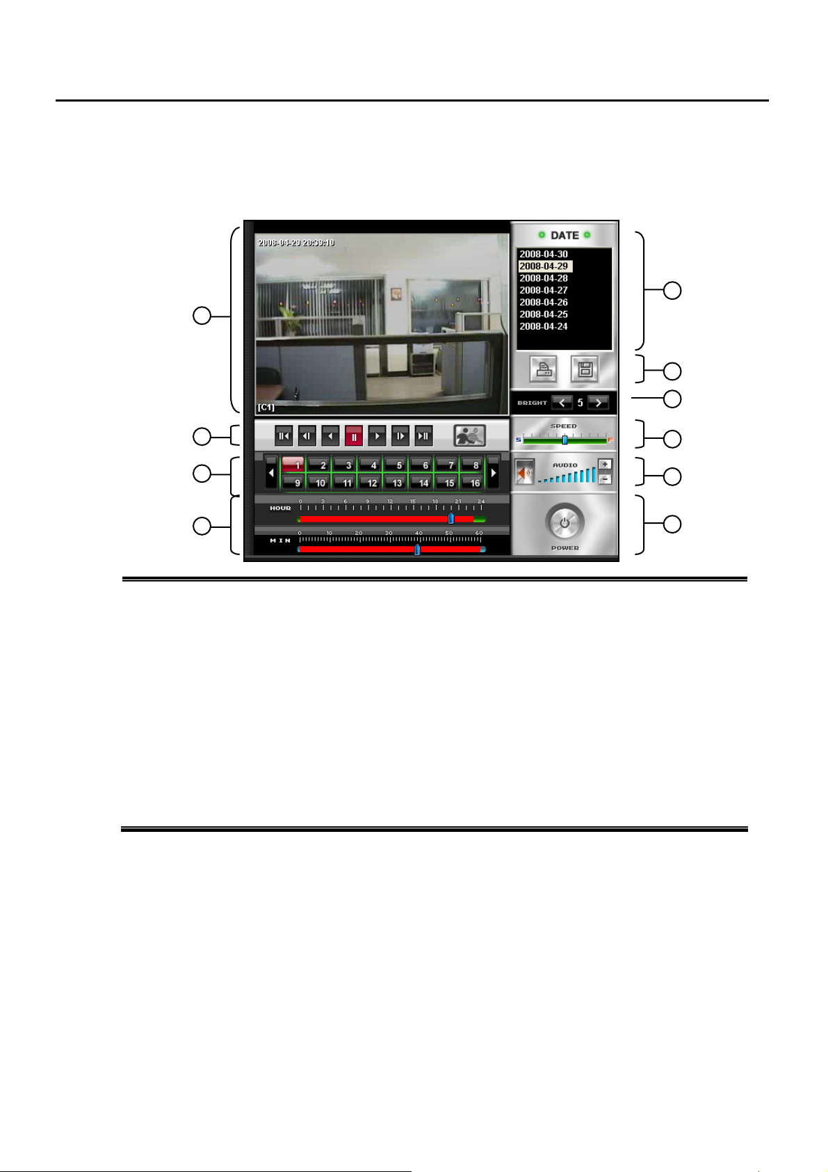
While Monitoring, by RIGHT CLICK of a Mouse, you can playback, copy and print Recorded data.
(Ref: #8 of chapter 2.1)
1. Playback Screen – Shows recorded image.
2. Playback Control Buttons – To the first frame, Reverse frame by frame, Reverse Play,
Pause, Normal Playback, Playback frame by frame, to the Last (from the left)
De-interlace Filter Button – decrease Interlacing Effect happening in recorded data with D1 resolution
(720x480 NTSC, 720x576 PAL)
3. Camera Selection Buttons – Select the camera you would like to play back.
4. Time Selector – Select a specific time that you would like to play back
5. Date List – Shows date list that have recorded data. You can select a day
6. Print Button – Printing image. Save Button – Save image as JPG or AVI or EXE.
7. Brightness Control –adjust brightness of recorded image.
8. Speed Control – Allows you to adjust playback speed.
9. Audio Volume Control – Adjusts audio volume level.
10. Exit Button – Exits Quick Play mode.
1
2
3
4
If not selected, it playback from the 1st data of each day
5
6
7
8
9
10
- 12 -
Page 13
2.2 Monitoring Menu
2.2.1 Camera View on Monitoring
REC A1
C9(location)
1
2
1) Recording Status: REC means Continuous Recording
Mode, Motion – Motion Detection Recoding , Sensor –
Sensor Detecting Recording Mode, Off – No Recording
2) Audio Status – shows Audio Recording Channel
3) Camera No and Site Name – display Camera Number and
its Location Name
3
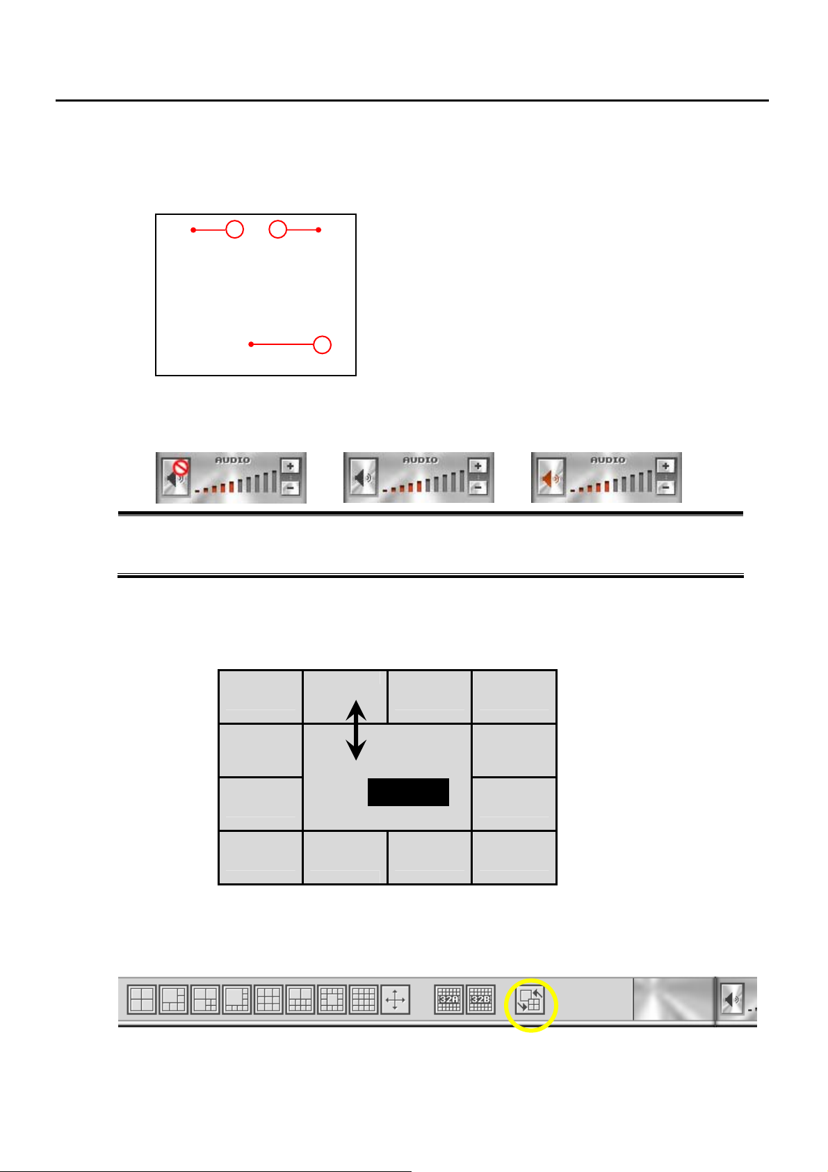
2.2.2 Audio Volume Control
① ② ③
1. It means Audio is not available or not connected.
2. Audio is being recorded. If you click the little Speaker Icon, you can listen to the audio
3. Recorded Audio is being played. You can control its volume with “+”, “-“ key
2.2.3 Switching Camera Position
By dragging a screen to another screen, you can switch a specific camera screen on the monitoring mode.
The following example shows that camera #2 and #6 screens are switched each other.
C2
C1
C6
C5 C7
C3 C4
2 <=> 6
C8
C10 C11 C12 C13
C9
2.2.4 Recovering Camera Position
By clicking Recover Position button on Monitoring mode, you can recover original camera’s position from
the switched camera’s positions.
- 13 -
Page 14
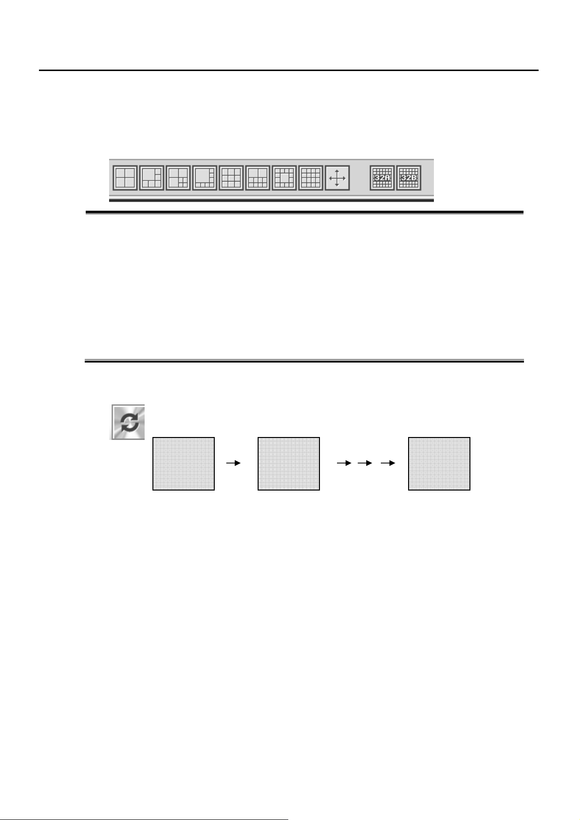
2.2.5 Screen Division Buttons
A screen can be divided into a various screen division as shown below. On each clicking this button, it changes to the
next camera image with same division screen.
(1) (2) (3) (4) (5) (6) (7) (8) (9) (10)
1. Quad Display – Displays camera 1~4, 5~8, 9~12, 13~16
2. 6 Division Screen – Displays 6 cameras in the display area.
3. 7 Division Screen – Displays 7 cameras
4. 8 Division Screen – Displays 8 cameras
5. 9 Division Screen – Displays 9 cameras
6. 10 Division Screen – Displays 10 cameras
7. 13 Division Screen – Displays 13 cameras
8. 16 Division Screen – Displays 16 cameras
9. Full Screen Display – Hide Menu bar and shows Camera(s) in full screen.
Right clicking on the full screen go back to the previous divided screen.
10. In case of model 6496, a screen can be changed to 2 x 32ch screens such as 32A (1~32), 32B (33~64).
2.2.6 Screen Auto-Switching
Automatically change Displaying Divisions to the next one.
You can adjust this switching time in Recording Frame Setup (chapter 3.2)
Camera 1 Camera 2
3 seconds
Camera 16
- 14 -
Page 15

r
Setup Mode
3. Setup Mode Overview
3.1 Camera Setup
3.1.1 Link to Sensor
3.1.2 Link to Control
3.1.3 Full Screen Setup
3.1.4 PTZ Protocol Setup
3.1.5 Default Camera Setting
3.2 Recording Frame Setup
3.2.1 Intensive Recording setting
3.2.2 Regular Interval Recording setting
3.2.3 Video Loss setting
3.2.4 TV Out setting
3.3 Recording Schedule
3.4 Special Day Recording Setup
3.5 Motion Setup
3.6 Sensor Setup
3.7 Control Setup
3.8 User Registration
3.8.1 User Add/Edit
3.9 System Setup
3.9.1 Disk Management
3.9.2 E-mail Setup
3.10 Network Setup
3.10.1 DDNS Setup
3.10.2 Network Setup
3.11 Log Information
Chapte
3
- 15 -
Page 16
3. Setup Mode Overview
Setup Mode adjusts options such as Recording Schedules, Recording Mode, Motion
Detection, Network and so on.
Factory default ID is administrator without password.
You’d better to change or make your own ID and password for security.
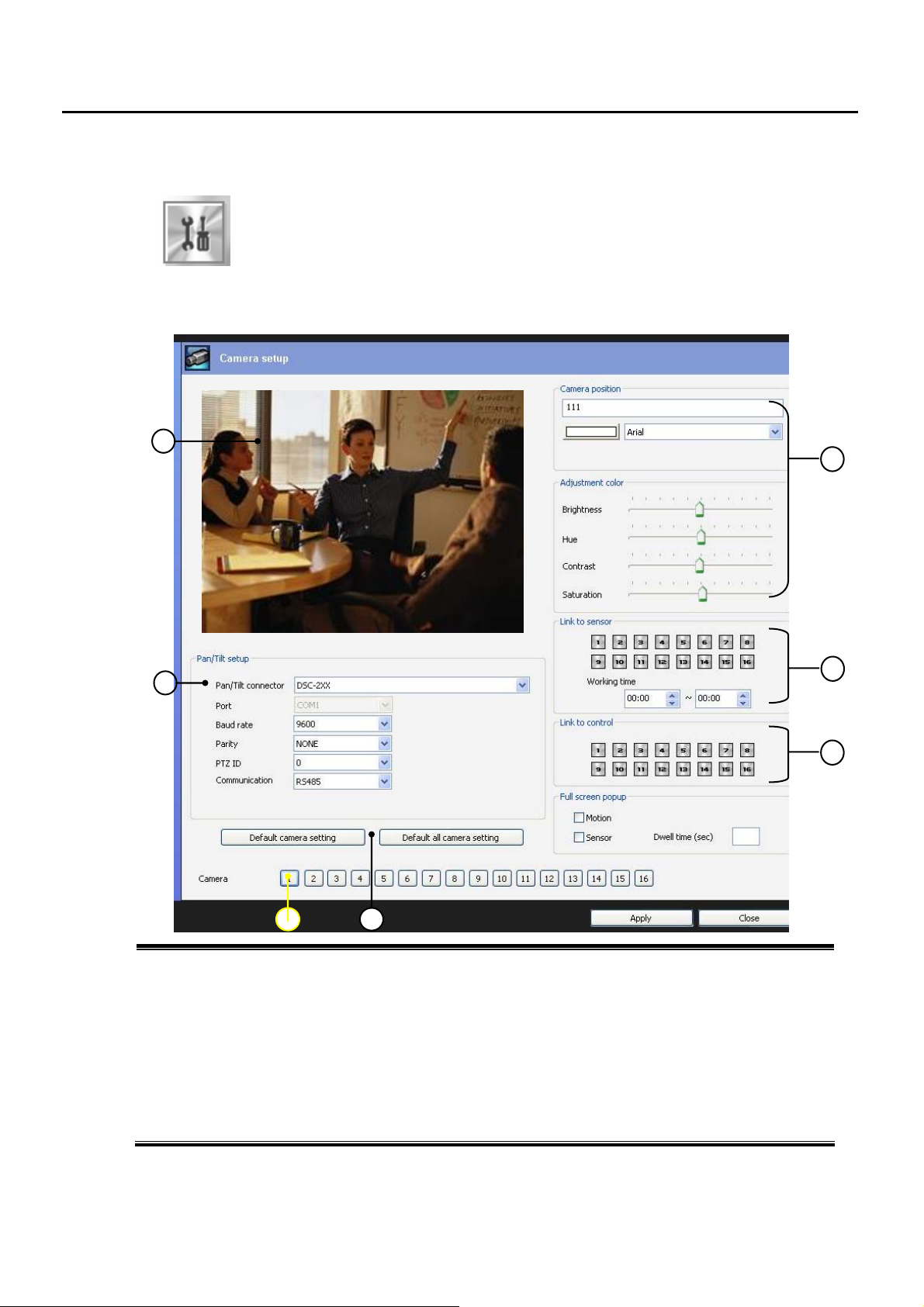
3.1 Camera Setup
5
6
1
8
2
3
4
1. Camera Selector– Select Camera you want to set
2. Camera Position – you can input Camera’s Position Name, font style and color
Color Adjustment – you can adjust brightness, contrast of Monitoring display
3. Link to Sensor – Link Sensor(s) to the selected camera.
4. Link to Control Output – Link Control(s) (like Siren, Light, Speaker, etc) with the camera
5. Full Screen Popup – Displays FULL SCREEN when Motion or Sensor is detected.
6. Camera Viewing Window – Displays a selected camera scene
7. Pan/Tilt Setup – select PTZ Protocols, communication, band rate, etc.
8. Default Camera Setting – choose Default setting for a camera or all cameras
* Make it sure to save or apply updated setting before close
- 16 -
Page 17
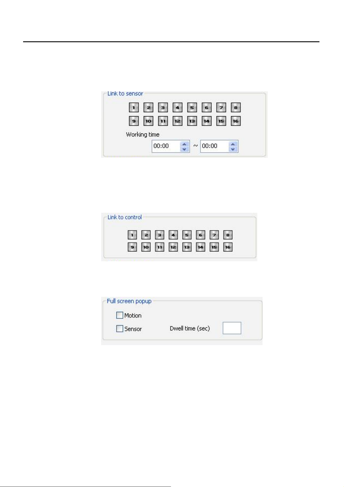
3.1.1 Link to Sensor
You can link a Sensor or multiple Sensors to the selected Camera. Also you can appoint Working Time for
those selected Sensors.
3.1.2 Link to Control
You can link a Control or multiple Controls to the selected Camera.
As for detailed setting for each Control, please refer to chapter 3.7 Control Setup.
3.1.3 Full Screen Popup
Adjust to display a camera in full screen when motion or sensor is detected.
- 17 -
Page 18
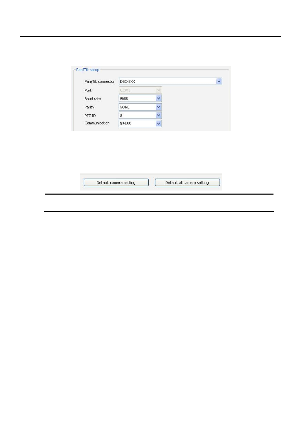
3.1.4 PTZ Protocol Setup
Select proper Protocol, Baud Rate, Parity, PTZ ID and Communication according to PTZ models,
3.1.5 Default Camera Setting
Default Camera Setting – adjust Factory Default Setting for a camera.
Default All Camera Setting – adjust Factory Default Setting for ALL cameras
- 18 -
Page 19
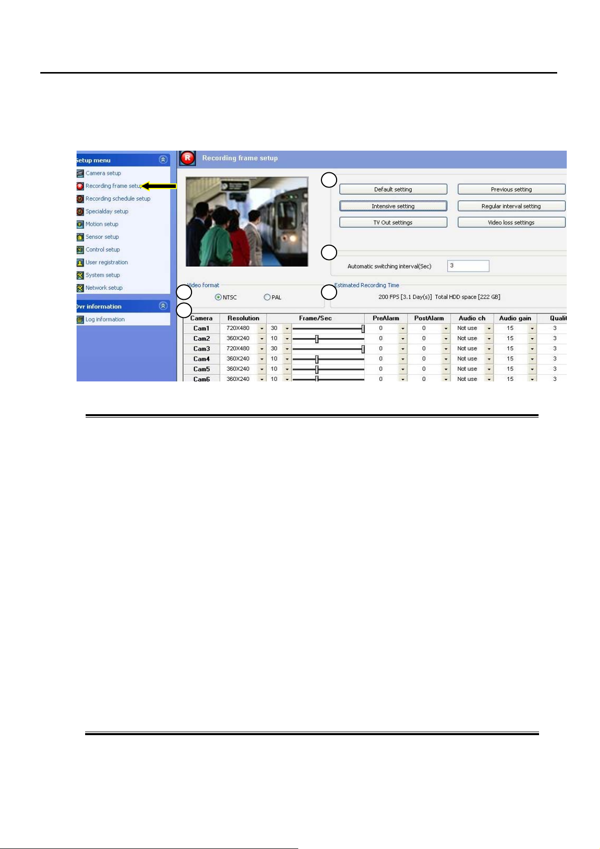
3.2 Recording Frame Setup
Adjust Recording Frame, Resolution, Pre/Post Alarm, Audio and so on.
3
5
1. Default Settings – set all cameras as default setting.
Previous Settings – set all cameras as previous setting.
Intensive Settings – adjust Intensive Recording Options (ref 3.2.1 Intensive Recording)
Regular Interval Settings – adjust Regular interval setting (refer 3.2.2 Regular Interval)
Video Loss Setting – adjust options for the case when there is no video signal (refer 3.2.3)
TV Out Settings –TV out Options setting (refer to chapter 3.2.4 TV Out setting)
2. Automatic Switching Interval – adjust the interval time of Auto-Switching Camera Screen
3. Video Format– select the Video Format only if you have to change the format. You need to re-start DVR
program to apply this setting
4. Estimated Recording Time – Displays the estimated recording duration according to current recording frame
setup. (After then, the old data is deleted automatically)
5. Recording Resolution, Speed, Pre/Post Alarm, Audio, Image Quality setting
Resolution: you can select recording resolution among 360x240, 720 x 240 and 720 x 480
(in case of PAL: 360x288, 720 x 288, 720 x 576)
Frame: select Recording Speed from 0 – 30fps (in case of PAL: 0-25) for each Camera
Pre-Alarm: select Recording Time before Event
Post-Alarm: select Recording Time after Event
Audio Ch: select Audio Channel which you want to link to the Camera
Audio Gain: select Recording Frame for Audio
Quality: select Image Quality of Recorded data, 3 is Normal.
1
2
4
- 19 -
Page 20
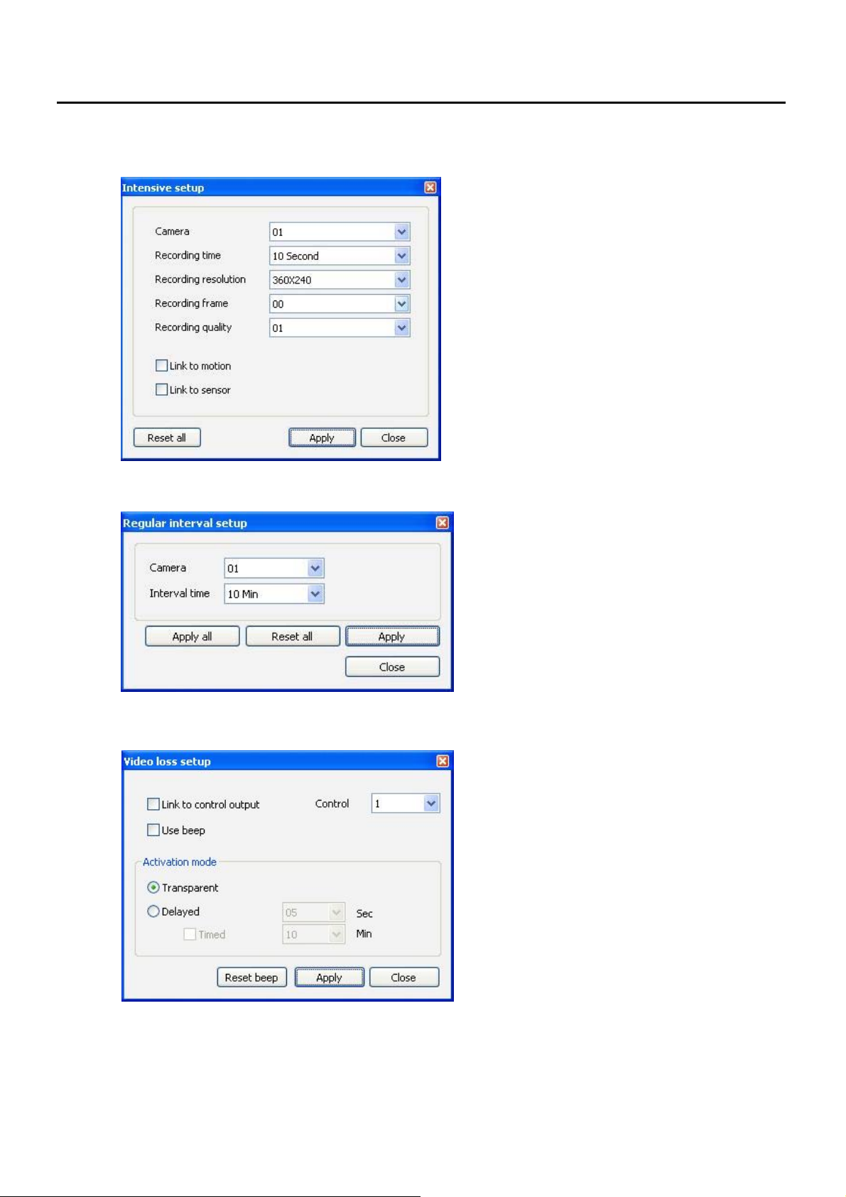
3.2.1 Intensive Recording Setting
You can set different Recording Speed and Resolution
for Event such as Motion and Sensor.
3.2.2 Regular Interval Recording Setting
If no image is recorded during a certain time (e.g.
30 minutes) when a camera is set to Motion or
Sensor recording mode, this Regular Interval
Recording function records one frame at the
adjusted interval times.
3.2.3 Video Loss Setting
Activate the Relay or Beep sound in case of Video
Loss.
* Link to Control: integrate Video Loss with
Control Output
(select Number of Control Ch)
* Use Beep: activate Beep Sound in case of
Video Loss
* Transparent: Immediately Activate
* Delayed: activate this setting after
adjusted time.
- 20 -
Page 21
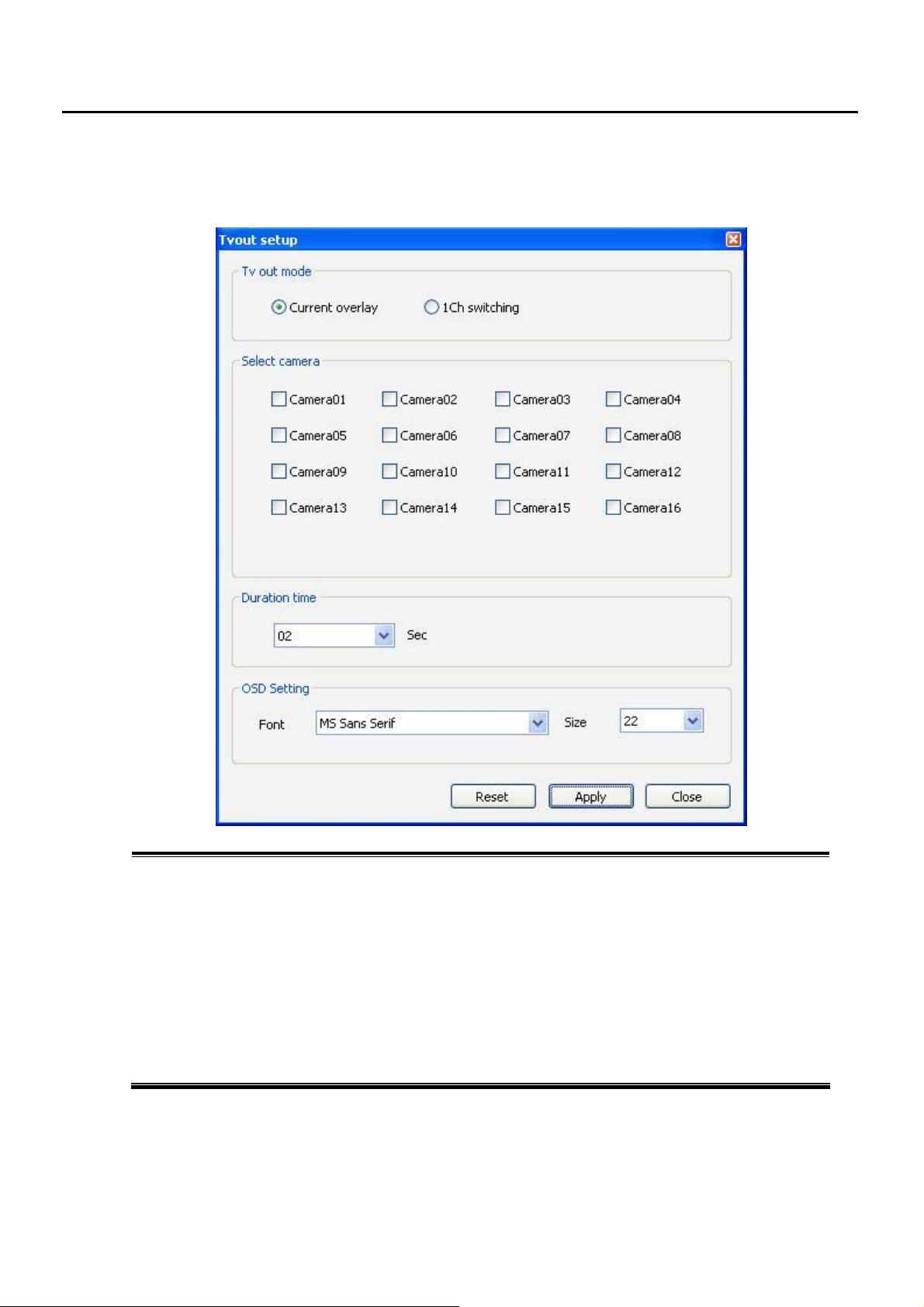
3.2.4 TV Out Setting
Adjust Display Setting of a Monitor which is connected to TV-Out jack of DVR
TV Out Mode – Select between Overlay Mode and 1ch Switching Mode.
1) Current Overlay: Displays the same screen as DVR.
2) 1ch switching: Displays each camera sequentially.
Select Camera – Select the camera that you would like to use for TV out.
In case of 32ch, 48ch, 64ch model:
you can select 1~16(Cam1~Cam16), 17~32, 33~48 and 49~64ch Group
Duration Time – Select the time Interval for 1ch Switching Mode
OSD Setting – Adjust the OSD font, size for TV out.
Optional TV Output – Adjust the OSD font, size and color for TV out.
Reset – clear all TV out settings.
- 21 -
Page 22
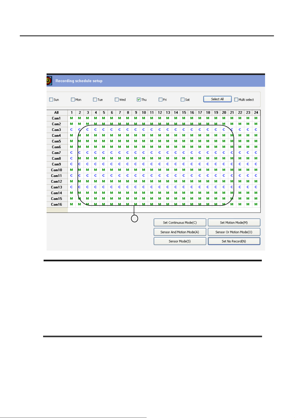
3.3 Recording Schedule
Set the RECORDING MODE for each camera per time, day.
Choose Day(s) or click Select All for the day you wan to set
Multi Select – for a case you want to set some days to be adjusted same
Camera & Time Select – click ALL or drag a mouse for the area (1) you want to adjust
C – Continuous Mode: recording all time
M – Motion Recording Mode: record only when there is Motion Detection
You can adjust Pre-Alarm to record the previous images before the Event (refer to 3.2)
A – Sensor & Motion: record only when Motion and Sensor detected together
O – Sensor Or Motion: record when Motion or Sensor is detected
S – Sensor mode : record only when Sensor is detected
N – NO Record : do not record for the select time and camera
1
- 22 -
Page 23
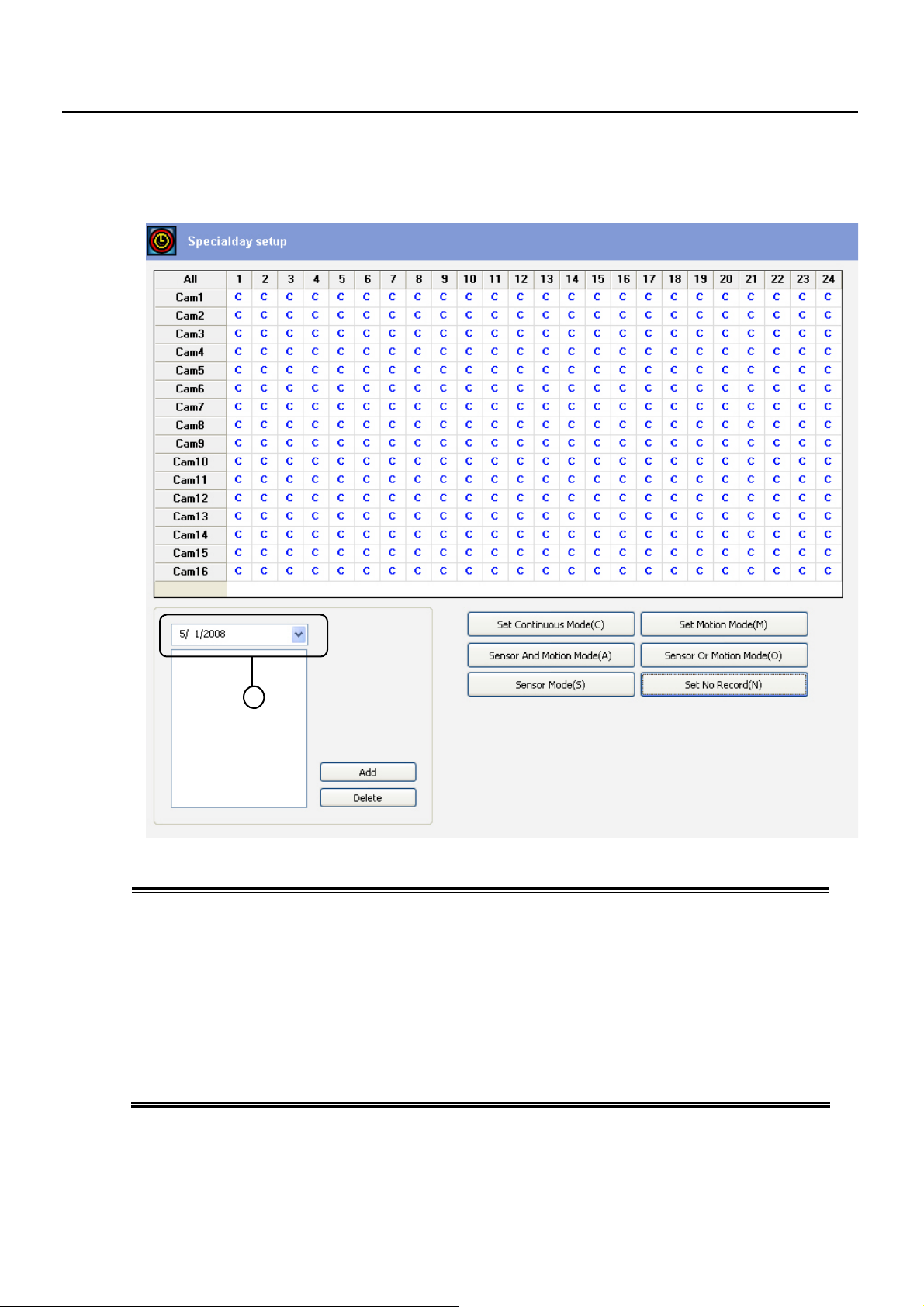
3.4 Special Day Recording Setup
You can set different RECORDING MODE for a certain day(s).
Choose Day (1) and ADD the day on the list
Camera & Time Select – click ALL or drag a mouse for the area you want to adjust
C – Continuous Mode: recording all time
M – Motion Recording Mode: record only when there is Motion Detection
You can adjust Pre-Alarm to record the previous images before the Event (refer to 3.2)
A – Sensor & Motion: record only when Motion and Sensor detected together
O – Sensor Or Motion: record when Motion or Sensor is detected
S – Sensor mode : record only when Sensor is detected
N – NO Record : do not record for the select time and camera
1
- 23 -
Page 24
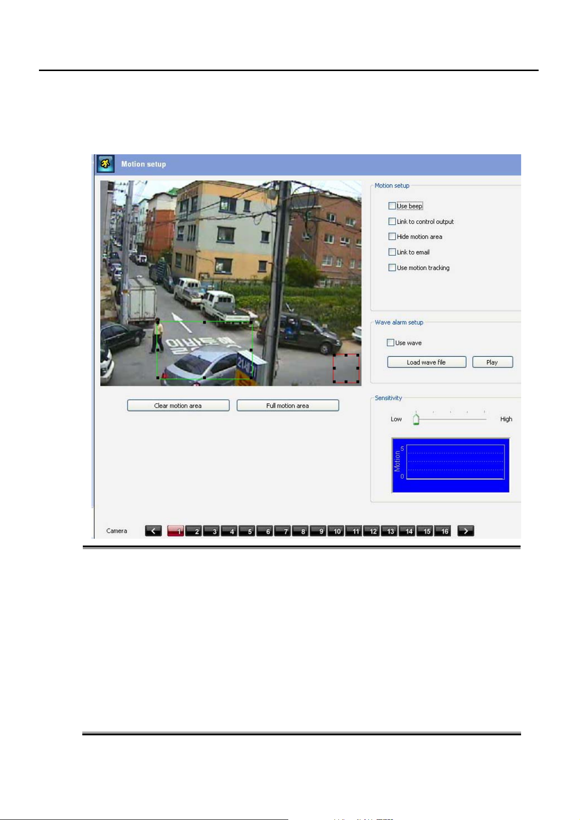
3.5 Motion Setup
You can set Motion related Setup like Motion Detection Area, Integration with Beep or Control Output, AUTO
MOTION TRACKING of PTZ Camera.
1. Select a Camera you want to adjust Motion Setup
2. You can make Motion Detection Area by drag a Mouse. If not selected, whole area is selected as default
3. Clear Motion Area – Delete the areas you selected
Full Motion Area – select whole area as Motion Detection Area which is Factory Default
4. Use Beep – activate Beep Sound when Motion is detected
Link to Control Output – Make Control Activated with Motion Detection
Hide Motion Area – Hide which area is selected so the other users can’t see which area is selected.
Link to Email – Send email with images when motion detected
User Motion Tracking – Set PTZ Camera to follow Moving Objects Automatically
“Recording Schedule 3.3” should be “Motion Mode” as well as you need to set Pan/Tilt Speed as MAX
(refer to chapter 6 PTZ, “Menu Start”)
* 4 camera can be set as Auto Motion Tracking as maximum.
7. Use Wave : activate Voice (WAV) file.
Load Wave File : select the Voice file saved in the unit and “PLAY” to test it.
8. Sensitivity – Sensitivity of Motion Detection
- 24 -
Page 25
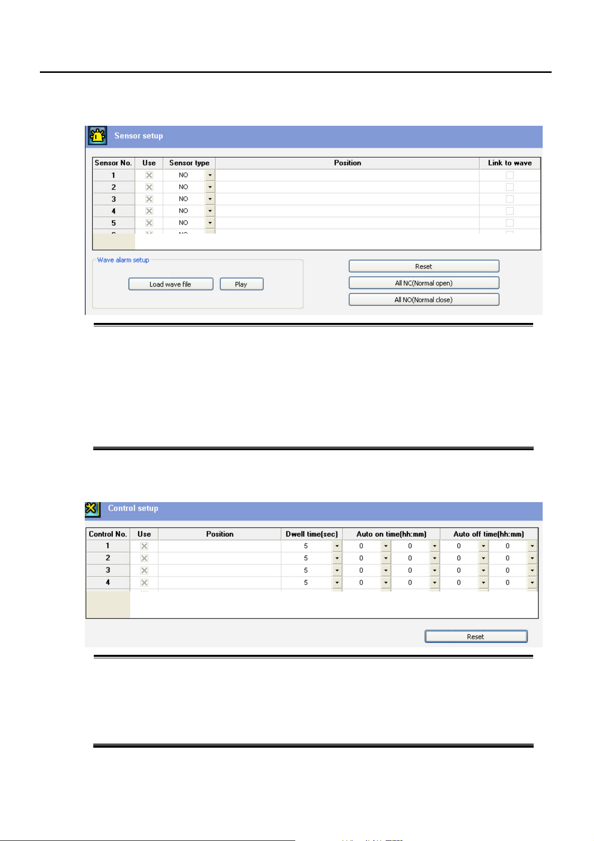
3.6 Sensor Setup
Set “X” for USE to activate SENSOR
Select SENSOR Type between NO (normal open) type and NC (normal close) type
Write the POSITION name of each SENSOR for reference
Link to WAVE file – when sensor is detected, selected WAV file will run
Wave Alarm Setup – choose WAV file
Play – test the sound of WAV file
RESET – clear all Sensor setting
ALL NC - adjust all Sensors type as NC (normal close) type
ALL NO – adjust all Sensors type as NO (normal open) type
3.7 Control Output Setup
Click to USE box “X” to activate Control
Enter the POSITION name of each Control Output for reference
Dwell Time – set Control Activating Time
Auto On Time – turn on Controls automatically on selected time
Auto Off Time – turn off Controls automatically on selected time
RESET – clear all Sensor setting
- 25 -
Page 26
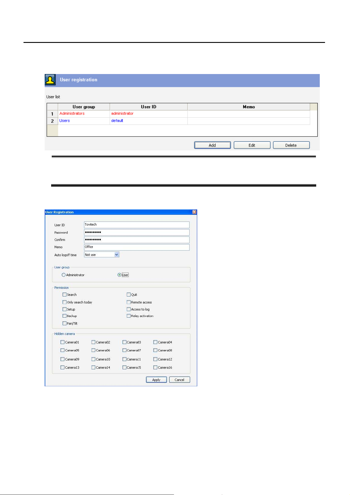
3.8 User Registration
ADD - Click ADD to add new USER
Edit - Select an ID and click Edit to change existing user’s information
Delete - Select an ID and click Edit to change existing user’s information
3.8.1 User ADD/EDIT
z User ID & Password:
Make User ID and Pass Word
z Confirm:
Input the Pass Word again
z Memo:
Memo about the User ID for your reference
z Auto Logoff Time:
You can make the User ID be logged-off
after a certain time
z User Group:
Choice Group of the User ID between
Administrator and User Group.
Administrator Group ID has full authority while
User Group may has limit in some functions.
z Permission or Hidden Camera:
You can permit function(s) to the User ID or
hide a camera from the ID
z Hidden Camera:
- 26 -
Page 27
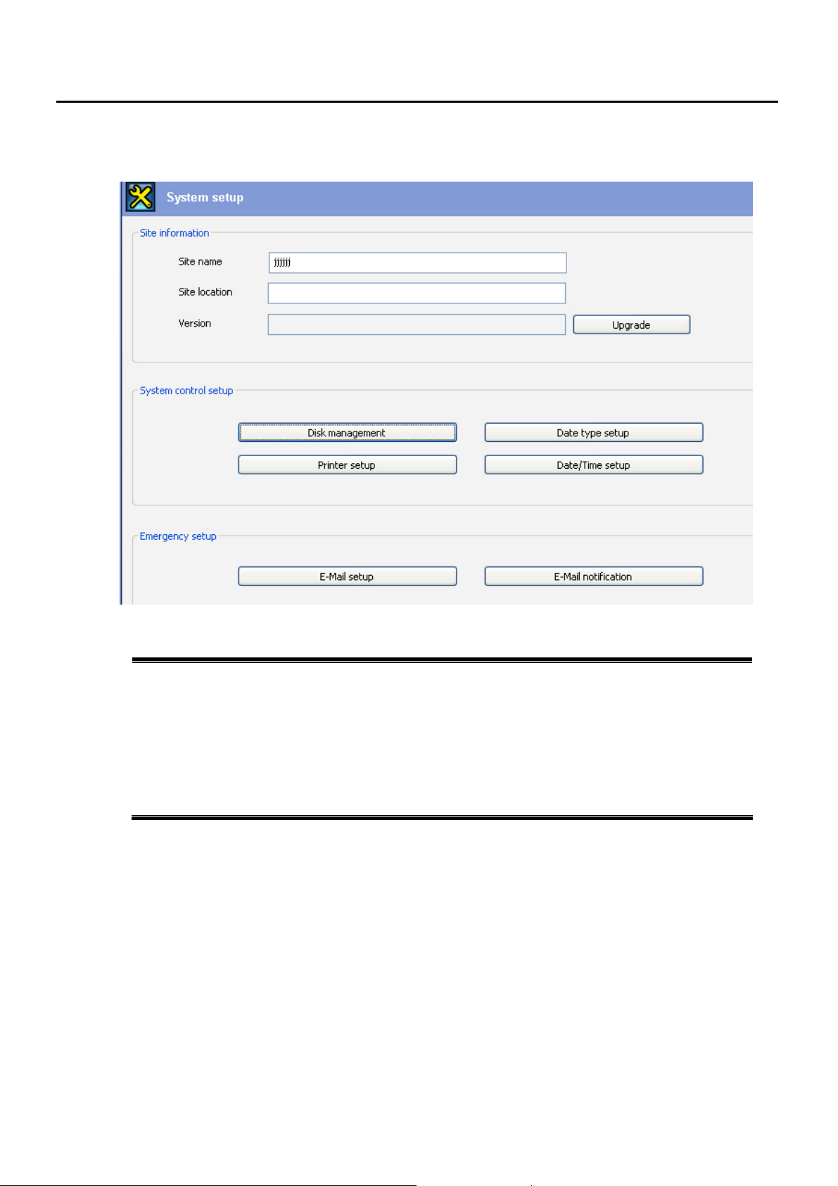
3.9 System Setup
Site Name & Location : enter the DVR site name and location for reference
Version & Update: DVR current software version shows and can be updated by a click
System Control Setup - Disk Management: manage Drives for Recording (see 3.9.1)
Date type Setup: adjust date type (e.g. 01-05-2008 or 2008-05-01 and so on)
Printer Setup: select or add Printer for DVR use
Date/Time Setup: adjust date/time of DVR
Emergency Setup - Email Setup: input E-mail Address where to send images when an event occurs
Email Notification: select Event Type which will send Image Files to the email address (see 3.9.2)
- 27 -
Page 28
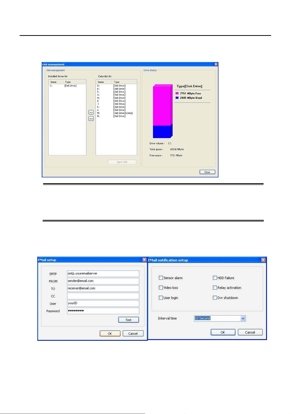
3.9.1 Disk Management
Installed Drive – Displays all installed disk drives which you can move to Data Disk List
Data Disk List – Displays those Drives being used for Recording. When one of the drives is full, data is
recorded in the next drive after formatting it. All data disk drives including network drive are displayed here.
The current using data disk drive can not be moved to installed drive or backup disk drive.
Eject USB – click the button when you want to remove USB Memory from DVR
Drive Status – Displays the status of the selected disk drive.
3.9.2 Email Setup
Input your own e-mail setting information. If you’re not sure about SMTP, User ID and Password, please contact
your network manager.
3.7.2 Email Notification Setup
■ E-mail Notification
Choose in which case, the email should be sent.
And you can choose interval time between email transmissions during the event.
- 28 -
Page 29
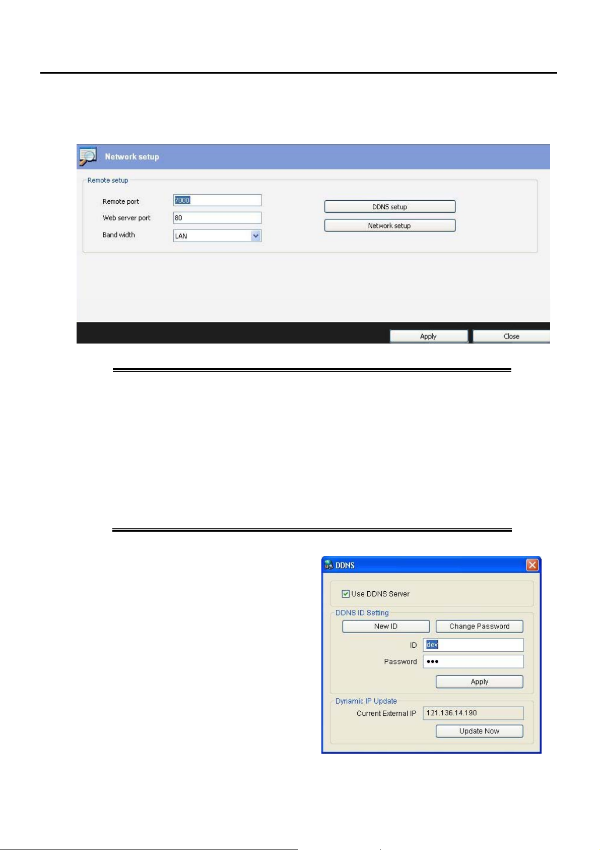
3.10 Network Setup
Adjust Options of Network Setting
Remote Port – default value is 7000. Input the Port Number you want to use for communication
with Client programs. In case you want to change default value 7000, please
reboot the system before use.
* Port Forwarding – In case the unit is connected to the internet via a router, you need to
set the port 7000 forwarded. Otherwise users can’t connect this unit from outside.
Web Server Port – Port used for Web Client. Factory default is 80
Bandwidth – You can choose Bandwidth which meets your network condition among
LAN, 128k, 64k, 56k, 336k, 288k, 144k, 96k, 5k
DDNS Setup – When you want to connect this NVR with IP address from outside, you’d better to
Use DDNS service. We provide FREE DDNS service that you can make your own
ID and Password for DDSN use with this menu
Network Setup – When you want to use Fixed IP address, set the Internet Protocol (TCP/IP)
3.10.1 DDNS Setup
DDNS (Dynamic DNS) server let user’s dynamic IP
can be used as fixed IP address.
So even though the IP address of NVR happen to
change, Users can connect to the NVR with Client
from remote places without problem.
Click “Use DDNS Server” and input your own ID and
Password before clicking “APPLY”
(You need to make NEW ID first, see 3.8.2)
After input your ID, Password, click “Update Now”
So DDNS server recognizes your IP address.
- 29 -
Page 30
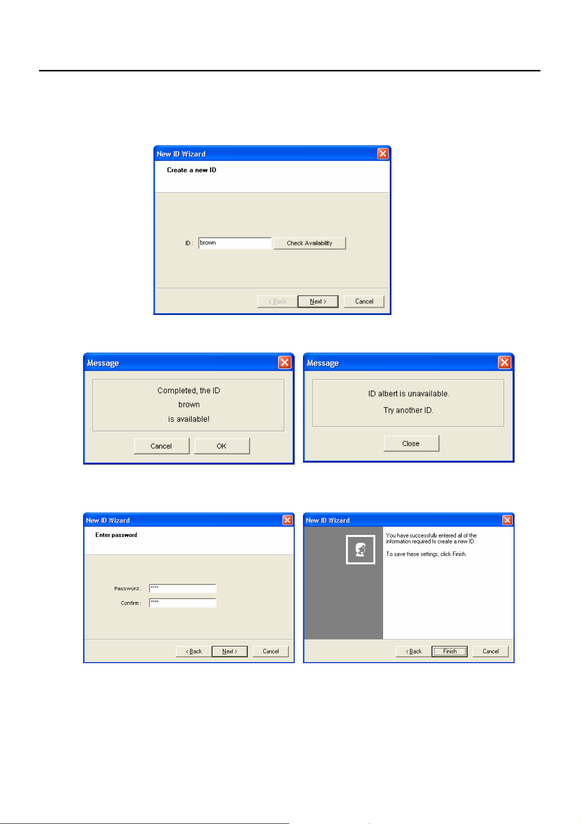
How to make your new ID in DDNS server
1) Click “NEW ID” button in 3.8.1 and below Window will appear.
Input your own ID and check its availability.
If your ID is available (meaning there is no same ID in this DDNS server), above “Available” windows will appear
and click OK. If the ID is not available, please try another ID after close above unavailable message.
After making ID, make its PASSWORD and confirm it by writing again.
Click “Next” and “Finish” to save this setting.
- 30 -
Page 31
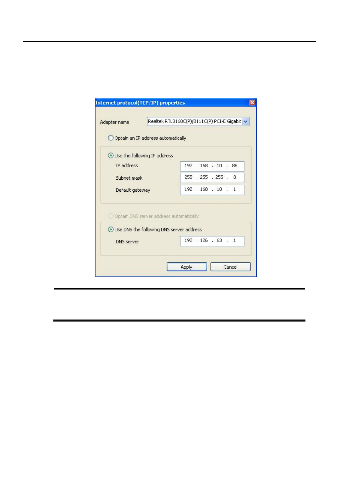
3.10.2 Network - Internet Protocol (TCP/IP) - Setup
Click “Network Setup” (see Chapter 3.8). Below Window will appear.
Please kindly consult Network Manager first if you’re not sure about this Setup.
Adapter Name – show the LAN card type of the DVR or your can change if this unit has another LAN card
Obtain an IP Address automatically – recommended when you’re not sure about this setup
Use the following IP address OR DNS – assign IP address for this unit.
- 31 -
Page 32
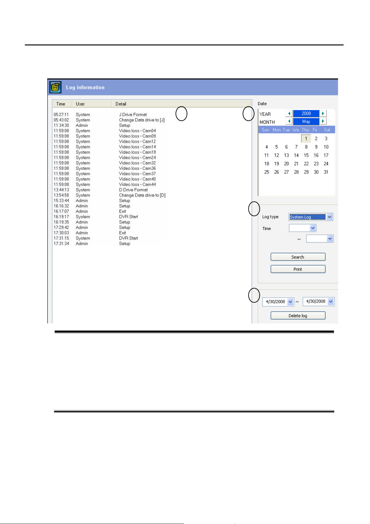
3.11 Log Information
1) Time – displays when the event occurs.
User– displays User ID who logged in
Detail – Displays system and event log.
2) Date – select the day when you want to look for the Log Information.
3) Log Type – select the Log type and duration you want to SEARCH
Print – Print the Log List.
4) Delete – delete Log information during the selected period
1 2
3
4
- 32 -
Page 33

r
Search Mode
4.1 Overview
4.1.1 Select Date and Time
4.1.2 Playback Control Buttons
4.1.3 Speed Options
4.1.4 De-interlacing Filter
4.1.5 Camera Enable and Selection Buttons
4.1.6 Screen Division Buttons
4.1.7 Audio Volume Control
4.2 Preview Search (Thumbnail Panorama Search)
4.3 Event Search
4.4 Object Search
4.5 Recording Status Table
4.6 Goto Search
4.7 Backup Play
4.8 Saving Images to JPG, AVI, Self-Executing EXE File
4.9 Printing Images
Chapte
4
- 33 -
Page 34
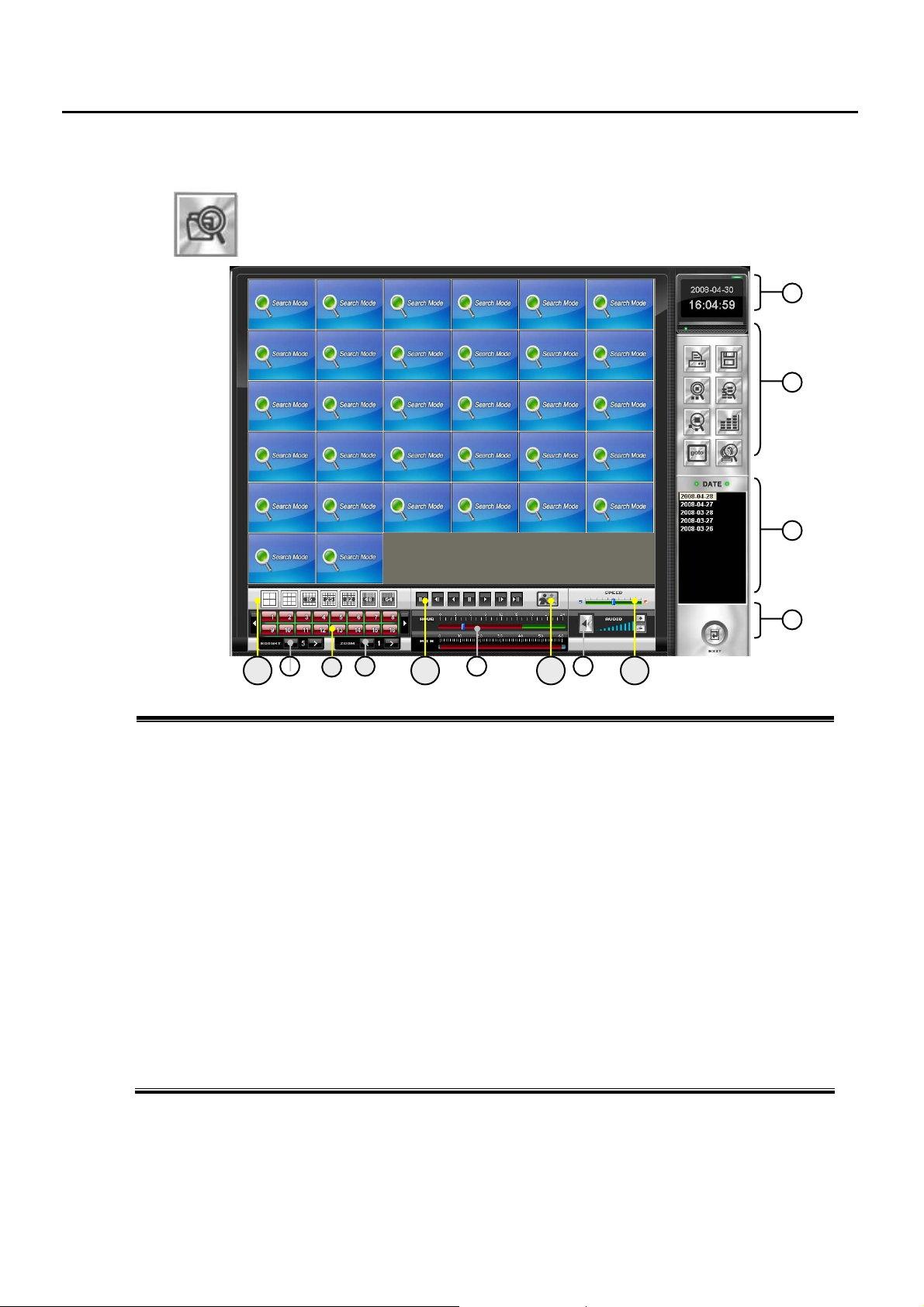
4.1 Search Mode Overview
Search the Recorded Data in Various Ways. If you just click the playback button “▶”,
recorded data of whole camera will be played from 00:00 of today.
You can set other options.
7
8
1013 11 12
6
59
1
2
3
4
1. Date and Time Indicator – Displays current date and time
2. Search Option Buttons – PRINT, SAVE, PREVIEW, EVENT, OBJECT, STATUS, GOTO, BACKUP PLAY
3. Date List – Shows Date with recorded data. You can select a day for search
4. Exit Button – Exits Search mode.
5. Audio Volume Control – Adjusts audio On/Off, Volume level.
6. Time Selector – Select a specific time that you would like to play back.
Red area has the recorded data
7. Zoom – adjust Zoom In/Out during playback of recorded image.
8. Camera Selection – Select the Camera No which you want to play back.
9. Brightness – adjust brightness for recorded image.
10. Playback Control Buttons – click to playback ‘backward frame by frame’, ‘backward’, ‘normal playback’,’
fast forward’ or ‘fast forward frame by frame’.
11. De-interlace Filter Button – make Image clearer by decreasing the Interlacing Effect happening D1
recorded image (720x480(NTSC) or 720x576(PAL)).
12. Speed Control – adjust playback speed.
13. Screen Division Buttons – select to see how many cameras simulatenously
- 34 -
Page 35
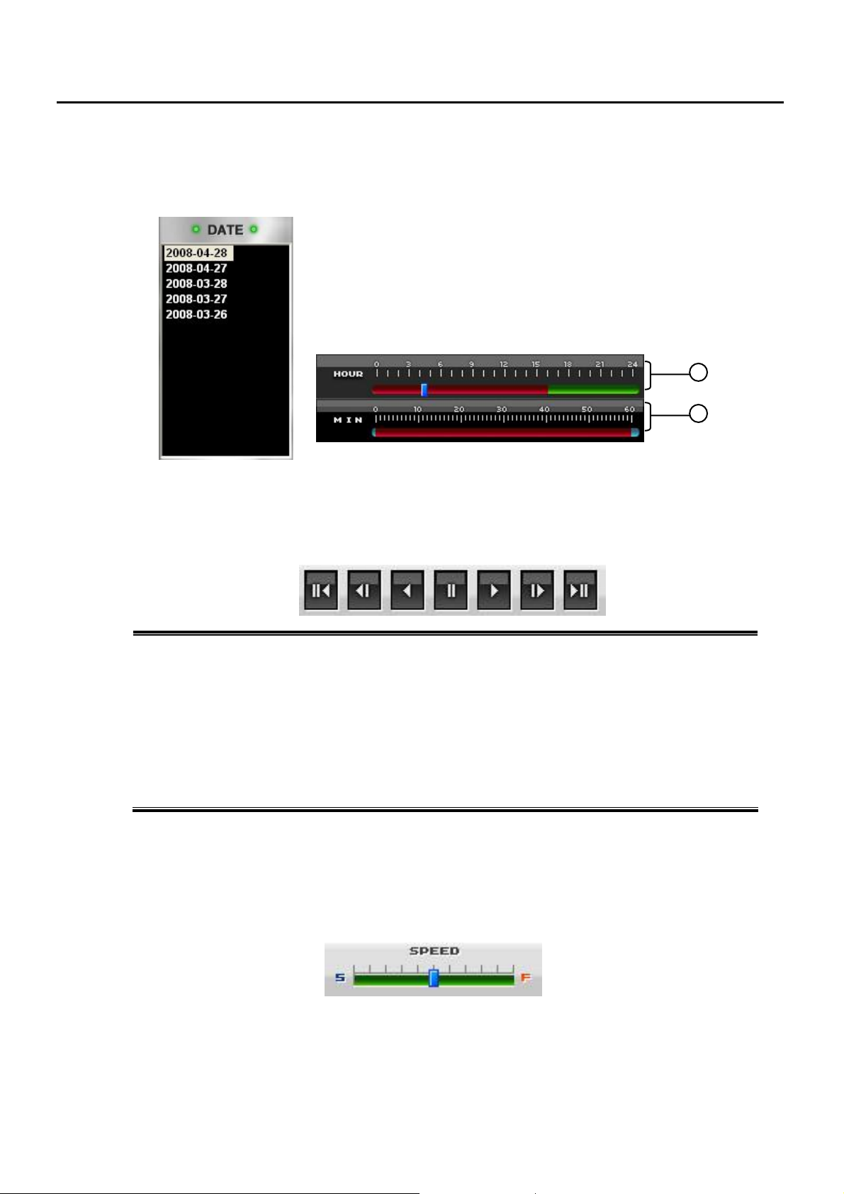
4.1.1 Select Date and Time
You can select a specific date and time which you want to search.
◀ day select
▼ Hour, Minutes select
(red area means it has recorded data at the hour and minutes)
4.1.2 Playback Control Buttons
you can play the image frame-by-frame, normal speed or backward.
① ② ③ ④ ⑤ ⑥ ⑦
1
2
1. Jump to beginning – Jumps to the first recorded image.
2. Play Reverse (frame-by-frame) – Plays the image one frame at a time (one frame each time when the
button is pressed)
3. Play Reverse – Plays the image in reverse.
4. Stop – Stops the image that is currently playing.
5. Play – Plays the image.
6. Play (frame-by-frame)– Plays the image one frame at a time (one frame each time when the button is
pressed)
7. Jump to End – Jumps to the last recorded image.
4.1.3 Speed Options
You can adjust playback speed. Move the slide bar right and left to speed up and down.
The playback speed options are 2x, 4x, 8x, 16x, 32x, 1/2x, 1/4x, 1/8x, 1/16x and 1/32x.
- 35 -
Page 36
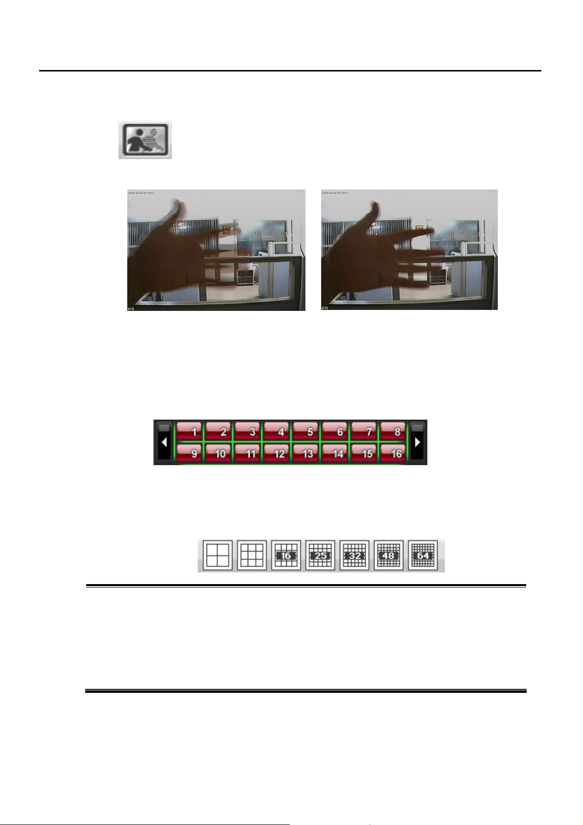
4.1.4 De-interlacing Filter
In 720x480(NTSC) or 720x576(PAL) resolution, the Interlacing Effect can happen
when there is a high speed movement. In this case, click this button during playback
in 720x480(NTSC) or 720x576(PAL), the interlaced tearing is decreased and image
is cleared.
Before Filtering After Filtering
4.1.5 Camera Enable and Selection Buttons
Enable (or disable) the Cameras to perform searches on. When you access to search mode, all cameras
are selected and enabled as a default. You can select cameras by simply pressing one or more camera
buttons. If a button is pressed, it is highlighted with RED color. It indicates a camera is being selected.
Press the button once more to cancel. The following figure shows all of cameras are selected.
4.1.6 Screen Division Buttons
You can view one or more sets of cameras at a time
① ② ③ ④ ⑤ ⑥ ⑦
1. Quad Screen – Displays camera 1~4, 5~8, 9~12, 13~16 in the video display area. On each clicking this
button, it change in order of 4 division screen such as 1~4, 5~8, 9~12, 13~16, 1~4 camera.
2. 9 Division Screen – Displays camera 1~9 in the video display area.
3. 16 Division Screen – Displays camera 1-16 in the video display area.
4. 25 Division Screen – Displays camera 1-25 in the video display area.
5. 32 Division Screen – Displays camera 1-32 in the video display area.
6. 48 Division Screen – Displays camera 1-48 in the video display area.
7. 64 Division Screen – Displays camera 1-64 in the video display area.
Single Screen – When a section of division screen is double-clicked, the selected screen is displayed in a
single screen. Double-click again on a single screen to return to the previous screen.
- 36 -
Page 37
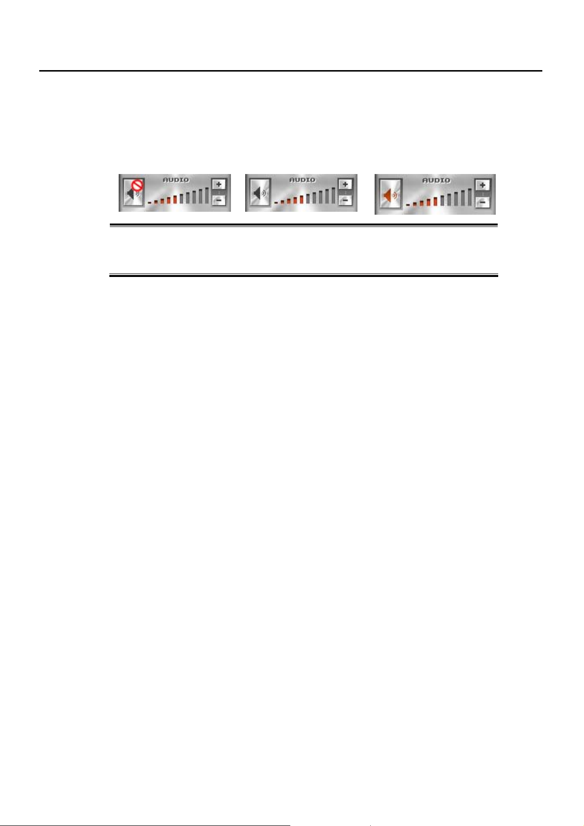
4.1.7 Audio Volume Control
You can turn-on the Audio of the Recorded Video Data (Optional function).
The sound will be audible through the speaker attached to DVR system.
① ② ③
1. No AUDIO DATA
2. AUDIO DATA is turned OFF
3. AUDIO DATA is turned ON, you can adjust its volume
- 37 -
Page 38
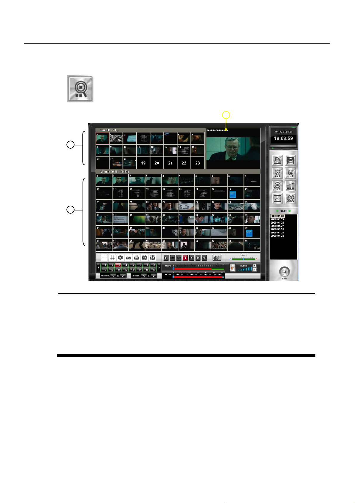
4.2 Preview Search (Thumbnail Panorama) (Search Option)
Click this button and it’ll show each frame of recorded data by hour on top area
(you need to select Camera first from below bar, if not selected: default is Camera #1)
If you click a frame of a-hour-data, this will show each minute data in 60 windows of the
selected hour. Select what you want and click Playback button.
1
2
1 Display Preview of each Hour per a day
When you click the Thumbnail Preview, it shows 24 images per each hour of a day respectively. When
there is no data during a hour, that area will show black screen.
2 Display Preview of each Minute per a hour
Click a image of hour in “1 – Preview by Hour” and it’ll show 60 images showing each minute of a
hour
3 Playback Window
Click a image among “2 – Preview by Minute” and click Playback Button
3
- 38 -
Page 39
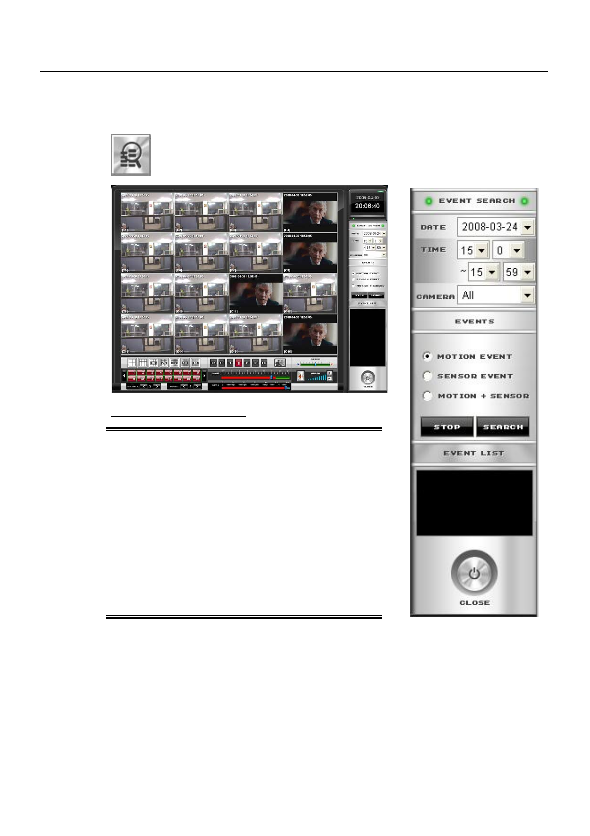
4.3 Event Search (Search Option)
You can search based on only events such as Motion Detection and Sensor Activation.
This search allows you to quickly narrow down large amounts of recorded image.
Event Search function is available in Multiple camera search or Single camera search mode,
not in Preview Search mode.
Event Search Options
Date – select a day you want to search
Time – select the hour and minute to search.
Camera – select a single camera to search or all cameras
Motion Event – Searches by all Motion events
Sensor Event – Searches by all Sensor events
Motion+Sensor – Searches on all events for the selected camera(s)
Stop – stop searching on events.
Search – start searching on events
Event List – Displays the Search Results. Displays the camera
number, time and event type. M: Motion, S: Sensor
The image will be displayed if you click one of them.
Click “Playback” button to play the video data
Close – return to the Main Search Screen.
- 39 -
Page 40
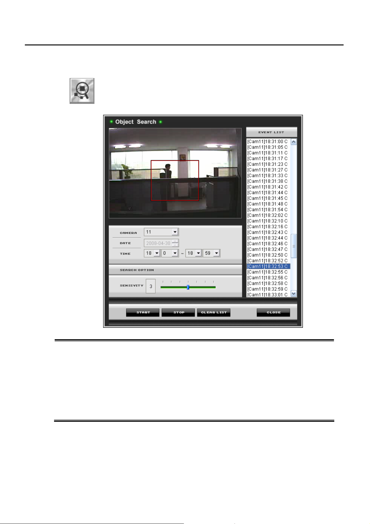
4.4 Object Search
during Playback, you can search Movement only in a Area you want to look for.
This function can be used when you want to find out since when a thing has been missing and
so on.
How to use OBJECT SEARCH
1) Click the Object Search button during Playback a Camera
2) Select a Camera, Date, Time on the above menu and draw a Area with a Mouse in which you want to
search. You can draw only one area for Object Search. If you draw one more area, previous area will
disappear.
3) Select Time, Motion Detection Sensibility before click START.
Data information will appear with Time Information on the List Window.
4) If you want to stop the process, click STOP and Event List will show the data searched till now
5) Click the Event Data and it will display the image of searched
6) Close to return to Search Mode
- 40 -
Page 41
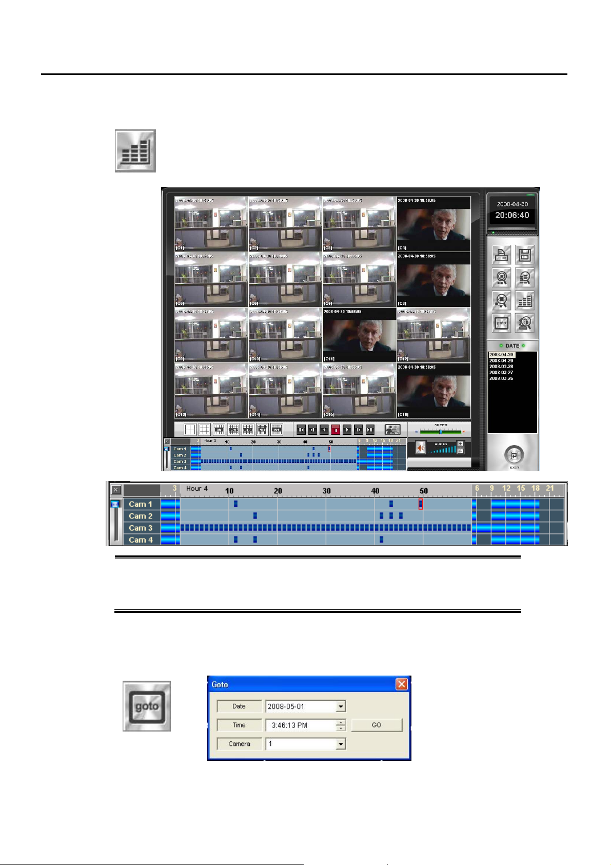
4.5 Recording Status Table (Search Option)
Show Recording Status
You can click a part in BLUE where you want to playback
Recording Status Table
The number in vertical line is camera’s number and horizontal line indicates time.
To see other camera’s status, use slide bar on left side.
If you click a specific hour, it will show 60-minute’s data of selected hour.
4.6 Goto Search (Search Option)
You can select exact time & camera number for playback with this option.
Click below button and select Date, Time, Camera Number before clicking GO
- 41 -
Page 42
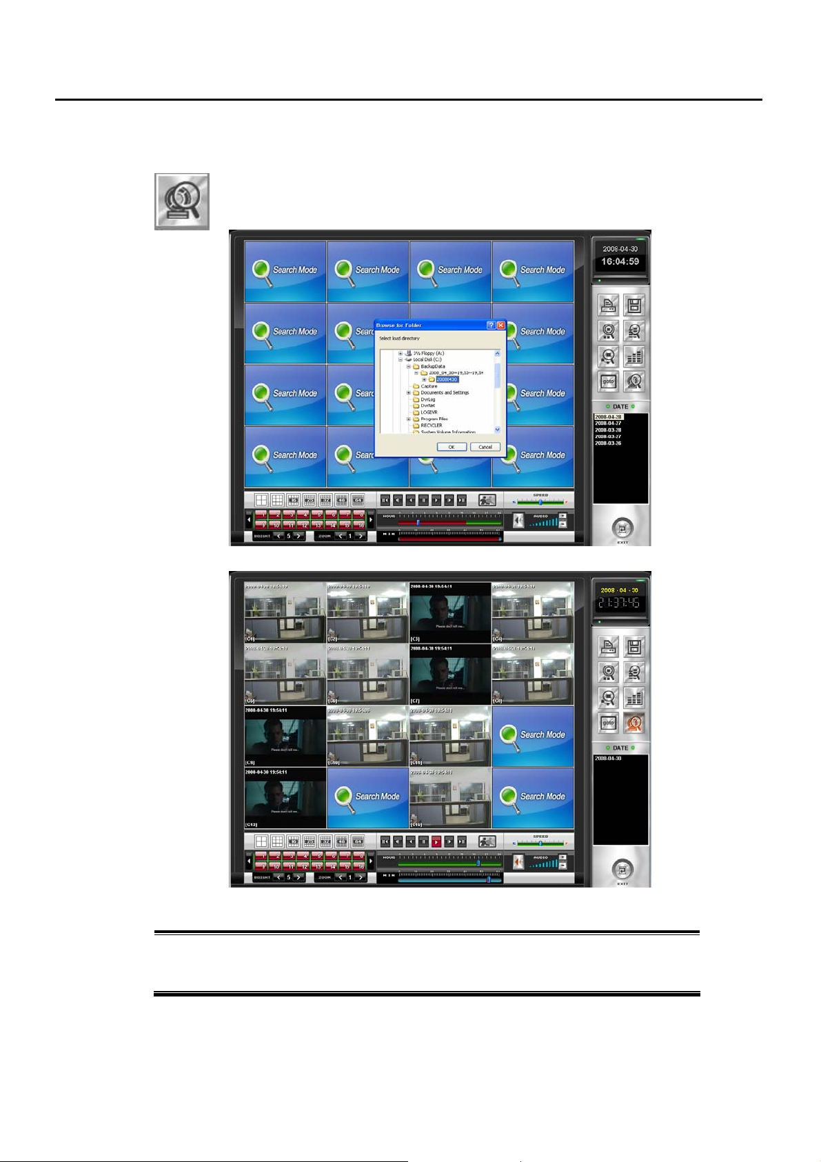
4.7 Playback of Backup file
You can playback the backup file from CD/DVD, USB HDD, and Network Drive.
Click The button and select the Directory where the data is saved.
Double click the data and it’ll be played if you click Playback button.
How to replay Backup Data
1) Select a drive that the recorded image has been saved.
2) Select a backup data folder which has the date.
3) Click ‘OK’ button. You can now replay the backed up images.
- 42 -
Page 43
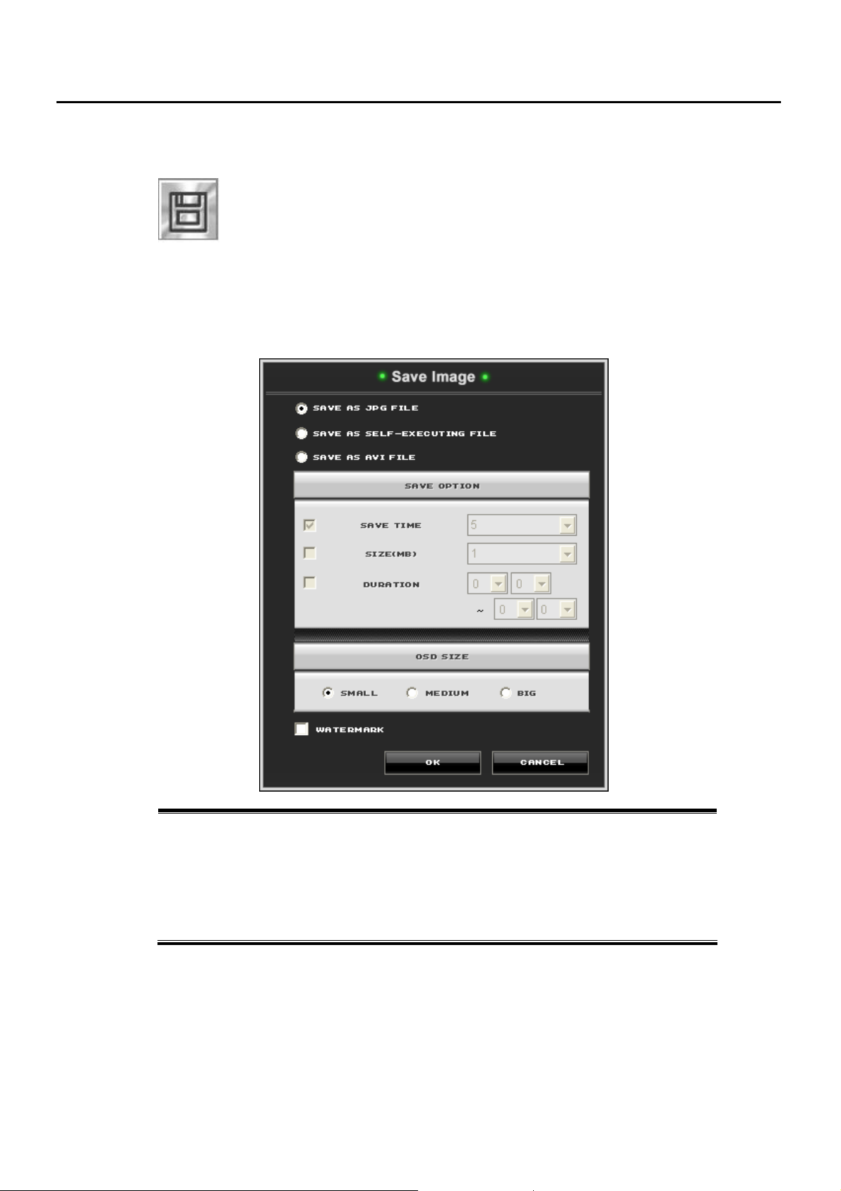
4.8 Saving images to JPG, AVI, Self-Executing (MPEG-4) File
What’s Self-Executing File Format?
This file format is our own developed software for video playback using MPEG-4 compression. This is
similar to AVI file but can be replayed without any program such as Windows Media Player. You can easily
replay the saved data in anywhere and any computer with more compressed file size. For replaying the
saved data, just click the saved file that has filename extension as “.exe”.
Save As JPG File – save a single image as JPG File Format.
Save As Self-Executing File – save a video clip as Self-Executing file(EXE).
Audio data is also saved with Video data in this format
Save As AVI File – save a video clip as AVI File Format.
Save Time – select duration to save the Self-Executing File or AVI File.
Make Button – start the saving process.
You can save the recorded data as JPG (Snapshot) or AVI, EXE file.
In case you save it as EXE file, you don’t need any other player to playback the data in
another PC.
Please note Audio is not supported in AVI file save.
- 43 -
Page 44
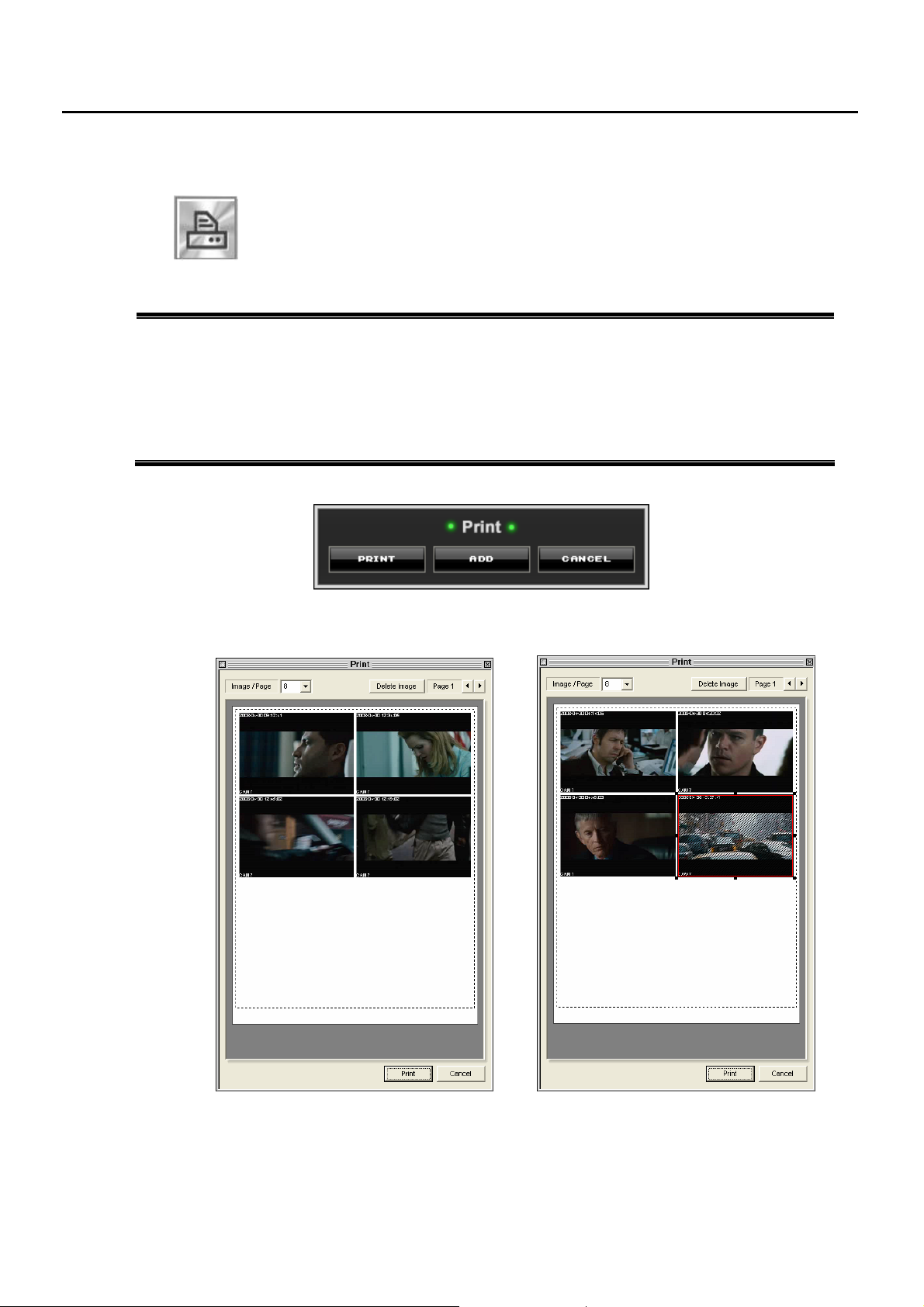
4.9 Printing Images
How to print images
1) From the Search Screen, click PRINT button. Click ADD button to add more images
2) After adding images, click ‘Print’ button on the Print Window. The preview screen will be shown, and you
can adjust the number of image to be printed. To delete image, click a certain image, and then click ‘Delete
Image’ button
3) To adjust the size of image to be printed, click a certain image and then enlarge or reduce the image using
mouse’s dragging
4) Press the ‘Print’ button to print the selected image.
This PRINT button allows you to print a stationary image on the search screen.
- 44 -
Page 45

r
Backup
Chapte
5
- 45 -
Page 46
5 Backup
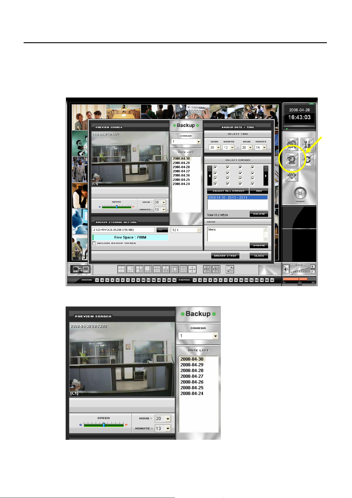
The DVR system can easily back up important image to an internal or external media location such as CDRW drive, DVD-RW drive, External Hard Disk Drive and Mapped Network Drive. To replay the backup data,
please refer to Section 4.7 ‘Backup Play’.
■ Preview Search Screen
Figure 50
It helps you to search the recorded
images that you would like to back up.
After searching the recorded images,
you can choose the date and time for
backup data.
- 46 -
Page 47
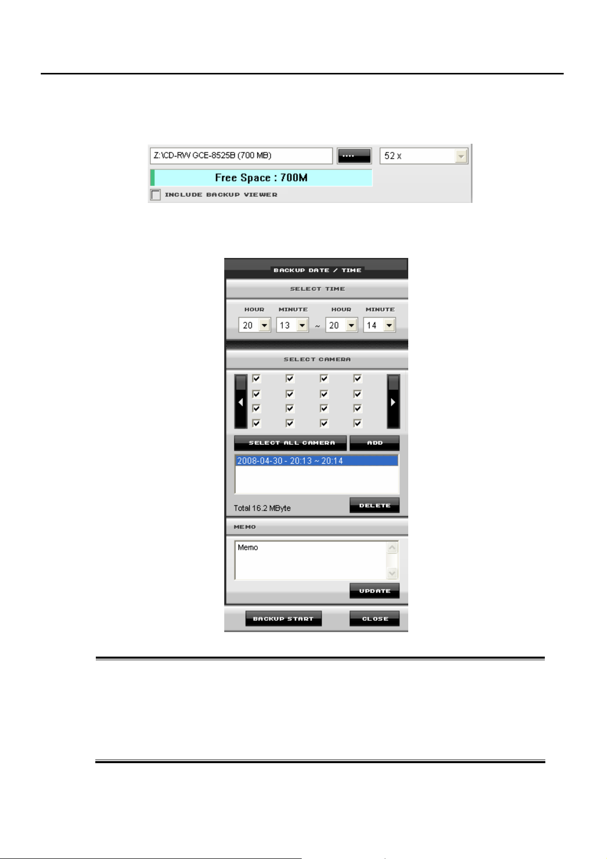
■ Backup Storage Setting
Select a drive for backup such as CD-RW and DVD-RW by clicking path button. Free space will be shown.
■ Starting Backup
To start backup
1) Select a date in the Date List box.
2) Select a starting and ending time.
3) Select cameras for backup. If there is no recorded images within a selected period of time, the check box
of camera is displayed with grey box.
4) If you would like to back up on and on, click Add button, and then select another date and time.
5) To make a note of backup information, enter it in memo box and then click Update button.
6) Click Backup Start button and then backup process will begin.
- 47 -
Page 48

r
Pan/Tilt/Zoom Control
6.1 PTZ Control Overview
6.2 PTZ Camera Setup
6.3 PTZ Options
6.4 Preset link with Sensor Alarm
Chapte
6
- 48 -
Page 49
6.1 PTZ Control Overview
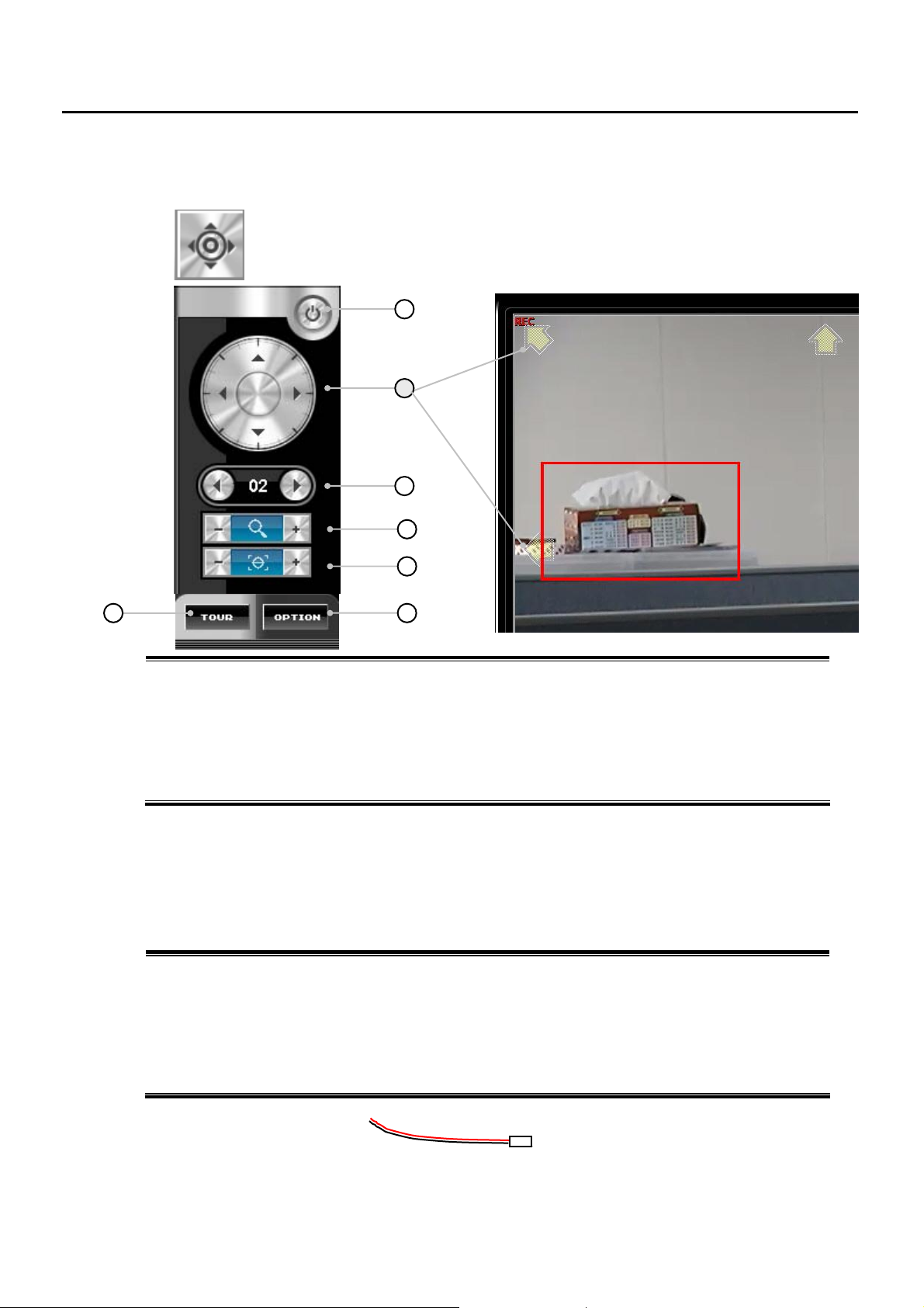
6
1. Exit Button – Return to the Monitoring Mode.
2. Pan/Tilt – click those ▲▼ buttons ◀▶ to control PAN/TILT.
3. Camera – Select PTZ camera by clicking the ◀ ▶ buttons.
4. Zoom – Use the buttons to zoom far and near.◀▶
5. Focus – Use the buttons to obtain the clearest picture.◀▶
6. Tour Button – Allows PTZ camera to move according to tour setting.
7. Options Button – Brings up the additional options menu.
When you press this button in Monitoring Mode, the following PTZ Control Window will be
shown. Connections of PTZ devices are required for PTZ control.
1
2
3
4
5
7
6.2 PTZ Camera Setup
The DVR system comes pre-assembled with an internal RS-422/485 adapter.
How to set a PTZ Camera
1) Locate the PTZ adapter. The PTZ adapter has two cables, red one for (+) and black one for (-).
2) Connect the PTZ adapter to the PTZ camera. Refer to your PTZ camera manual for detailed instructions.
3) In Setup Mode, select the camera number and then enable the PTZ control by selecting a proper
Protocol.
4) Press the APPLY button and exit Setup Mode.
5) From the Main Monitoring Screen, press the PTZ Control button. You can now control the PTZ camera
with PTZ Control options.
RS-422/485 adapter
- 49 -
Page 50
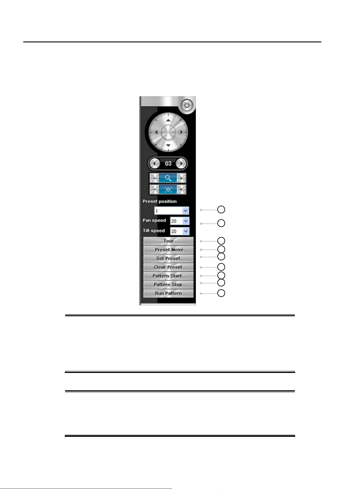
6.3 PTZ Options
When you click the Additional Options button, the following Window will be shown. The Additional Option
menu may not be available for all PTZ cameras. Those options are available only if the PTZ camera
manufacturer supports them.
1. Preset Position – Allows you to create Preset Positions.
2. Pan/Tilt Speed – Allows you to adjust Pan/Tilt speed.
3. Tour Set – Brings up ‘Tour Set window’.
4. Preset Move – Allows you to move PTZ camera to a preset position.
5. Set Preset – Allows you to save a preset position.
6. Clear Preset – Allows you to delete and clear a preset position.
7. Pattern Start
8. Pattern Stop
9. Run Pattern
How to create and move to a Preset Position
1) Move the selected camera to the desired position using UP, DOWN, LEFT and RIGHT button.
2) Once you have the camera in the desired position, select a ‘Preset Position’ number, and then
press ‘Preset Save’ button.
3) To move to a Preset Positions, select a ‘Preset Position’ number, and then press a ‘Preset
Move’ button.
4) To clear Preset Positions, select a ‘Preset Position’ number, and then press a ‘Preset Delete’
button.
1
2
3
4
5
6
7
8
9
- 50 -
Page 51
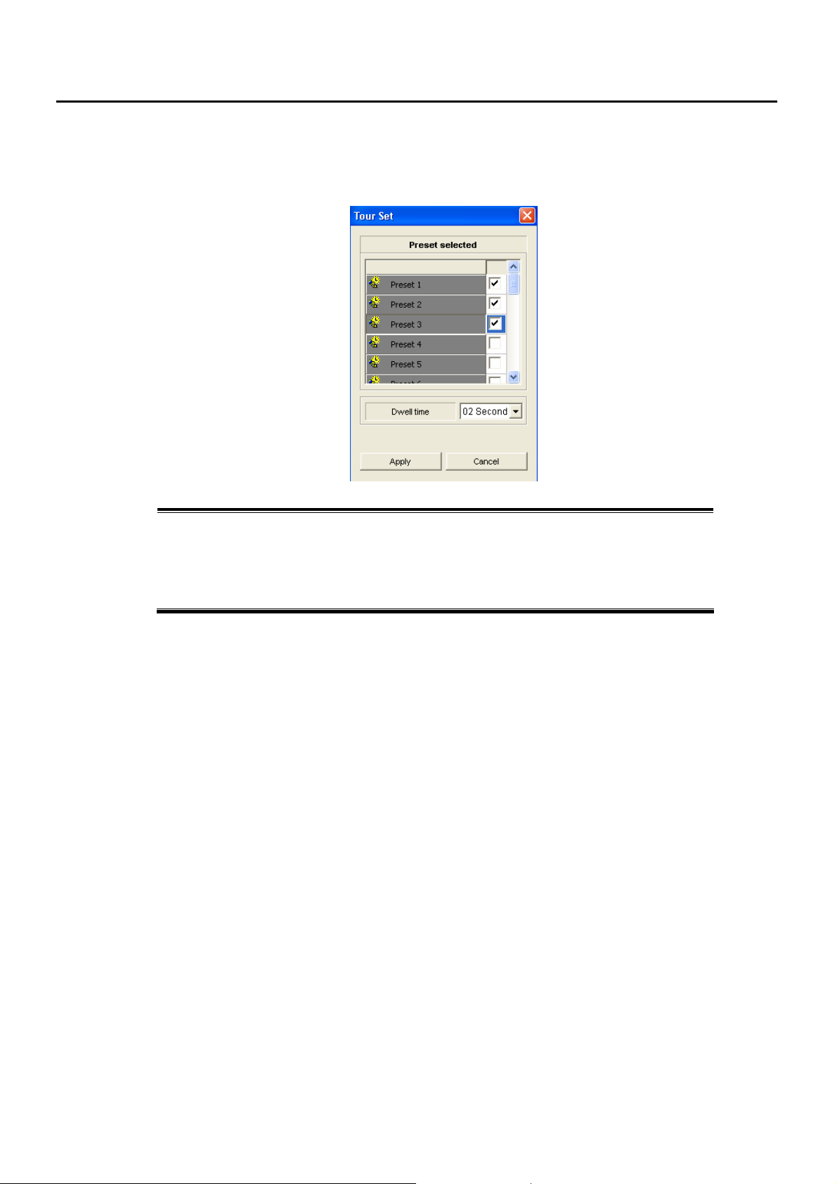
How to use Tour function
When you click the Tour Set button, the following Window will be shown.
1) Press ‘Tour Set’ button.
2) Choose and select preset position.
3) Set dwelling time before move to other position.
4) Make sure to save setting values by clicking Apply button.
5) To move and travel to preset positions, press ‘TOUR’ button.
- 51 -
Page 52
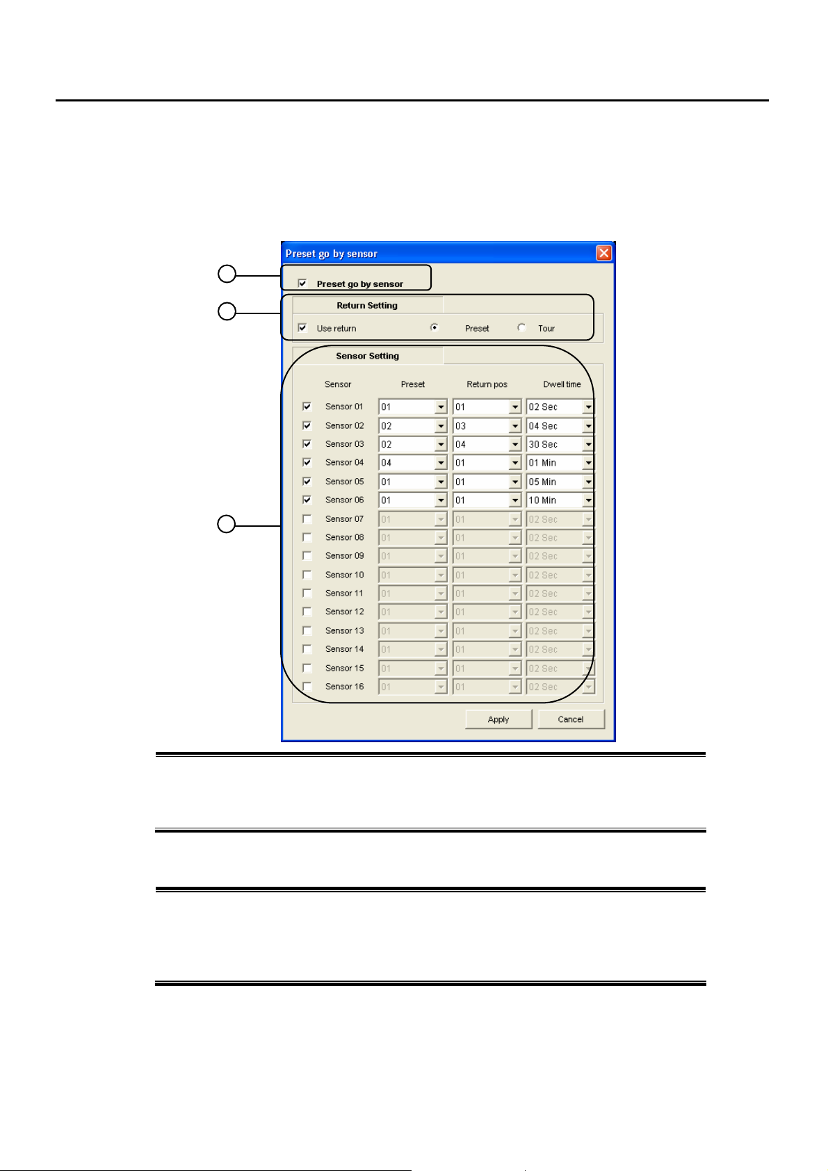
6.4 Preset link with Sensor Alarm
This function enables PTZ camera to move to preset position when the sensor is activated.
When you click the Sensor-Preset button, the following Window will be shown.
1. Preset go by sensor – Click and check to use this function.
2. Return Setting – Enables PTZ camera to return the moved preset to the desired position.
3. Sensor Setting – Select the desired sensors, preset position, return preset position and dwell
How to operate Preset link with Sensor Alarm
1) Check ‘Preset go by sensor’.
2) If you would like PTZ camera to return to the desired position, check ‘Use return’ and select
3) Select sensor which you would like to link to preset function.
4) Select preset position, return preset position and dwell time.
1
2
3
time.
‘Preset’ to return to the preset position or ‘Tour’ to adjust tour function.
- 52 -
Page 53

Client Programs
7.1 NetDVR Program
7.1.1 Program Installation
7.1.2 Monitoring Mode
7.1.3 Connection to NVR
7.2 Web Browser Connection
7.2.1 Connection & Monitoring Web Client
Chapter
7
- 53 -
Page 54

7.1 NetDVR Program
With NetDVR Program, you can connect to the NVR in remote place and view live image, Search/Playback
Recorded Data or adjust its setup.
The Display Speed of NetDVR Program is related with Recording Speed of the NVR.
If you increase Recording Speed of NVR, the Display Speed (frames per second) of Client program will be
increased. This speed is subject to change according to Network Environment.
Minimum Hardware Requirement for NetDVR Program use
■ CPU: Pentium III 800MHz or above
■ RAM: 128MB or above
■ Monitor Resolution: 1024x768
■ Monitor Color: 32Bit Color
■ Microsoft
®
Windows 2000 or XP
7.1.1 NetDVR Program Installation
1) Open ‘NVR Installer CD’ folder from CD or USB
2) Find NetDVRSetup folder and double-click NetDVRSetup.exe
3) The installation will be started. Please click ‘Next’ or ‘Yes’ according to its instruction
4) NetDVR icon will appear on Desktop after the installation finish
5) Double click the NetDVR icon
NOTE: Screen Resolution should be 1024 x 768 or above, Color Quality – highest 32bit
And Font Size - Normal
How to adjust SCREEN RESOLUTION of Display Properties:
1) Right Click Mouse on Desktop
2) Click PROPERTIES and Select SETTING among the Display Properties Menu
3) Adjust Screen Resolution – 1024x768 and Color Quality – Highest 32bit
How to adjust FONT SIZE:
1) Right Click Mouse on Desktop
2) Click PROPERTIES and Select APPEARANCE among the Display Properties Menu
3) Adjust FONT SIZE as NORMAL
- 54 -
Page 55
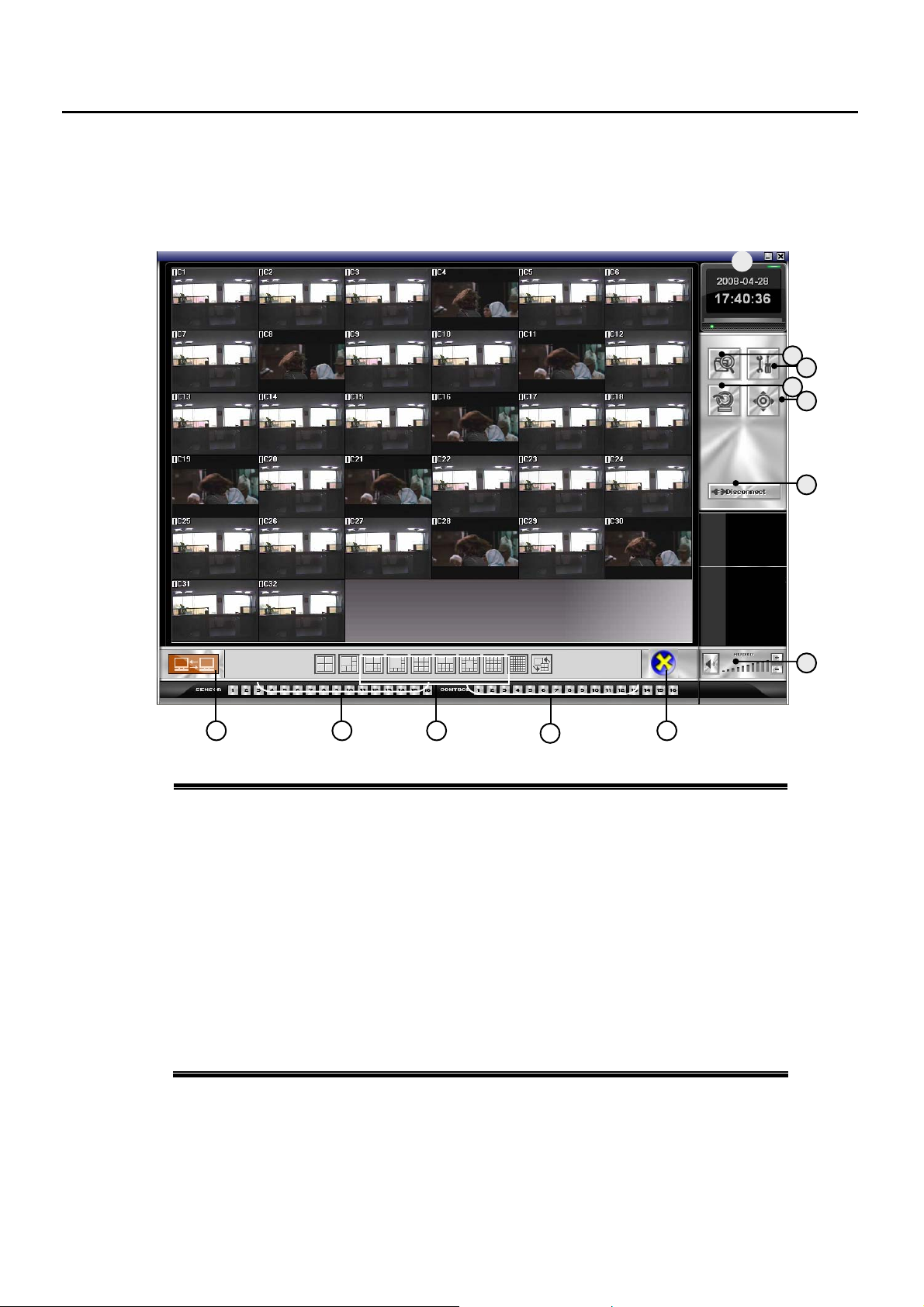
0
9
7.1.2 Monitoring of NetDVR
Those MENU of NetDVR Program is very similar with that of NVR or DVR Program.
So please kindly refer to the page of same function of NVR for detail information.
12 13
1 Day/Time Display – show Today Time
Minimize Button - minimize the window of NetDVR program
Exit Button - Exit from NetDVR program
2 Search – Search Recorded data of remote NVR
3 Setup – Adjust Setting of remote NVR
4 Backup – Backup data of remote NVR to your PC
5 PTZ Control – control PTZ of the Camera connected to the remote NVR
6 Disconnect – Disconnect the remote NVR
8 Audio Volume Control – Turn on Audio, Control Volume
9 Control Output Display – Display status of Control connected to the DVR or NVR
10 Screen Division Button – You can Monitoring in various types of Screen Divisions
11 Sensor Display – Display Sensor Status connected to the NVR or DVR
12 Network Connection Button – Click for connection with the remote NVR or DVR
13 DirectX Button – In case Image is strange in Monitoring, click this button.
It’s for when your PC is not compatible with DirectX
11 1
1
2
3
4
5
6
8
- 55 -
Page 56
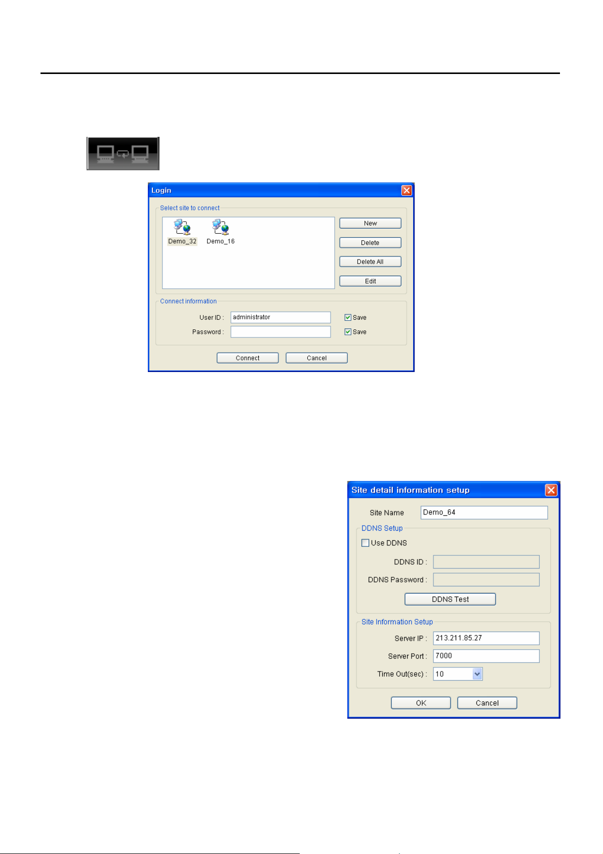
7.1.3 Connection NetDVR to NVR or DVR
Click the NETWORK CONNECTION icon and below LOGIN Windows will appear.
Select a Site of DVR, NVR you want t connect and input User ID, Password before click
z NEW : Add a NVR, DVR site
z Delete: Delete a NVR or DVR site from this Login Window
z Delete all: Delete all these Sites
z Edit: Edit a site information
z User ID: User ID of NVR or DVR
z Password: Password of NVR or DVR
How to Add a Site of NVR, DVR
1) click NEW button
2) click USE DDNS if the NVR or DVR is using
DDNS service.
Input DDNS ID and DDNS Password
3) if the NVR or DVR is not using DDNS service,
input SERVER IP and its port.
z Time Out: The Connection is tried during this time,
Connect Button
- 56 -
Page 57
0
9
7.2 Web Brower Connection
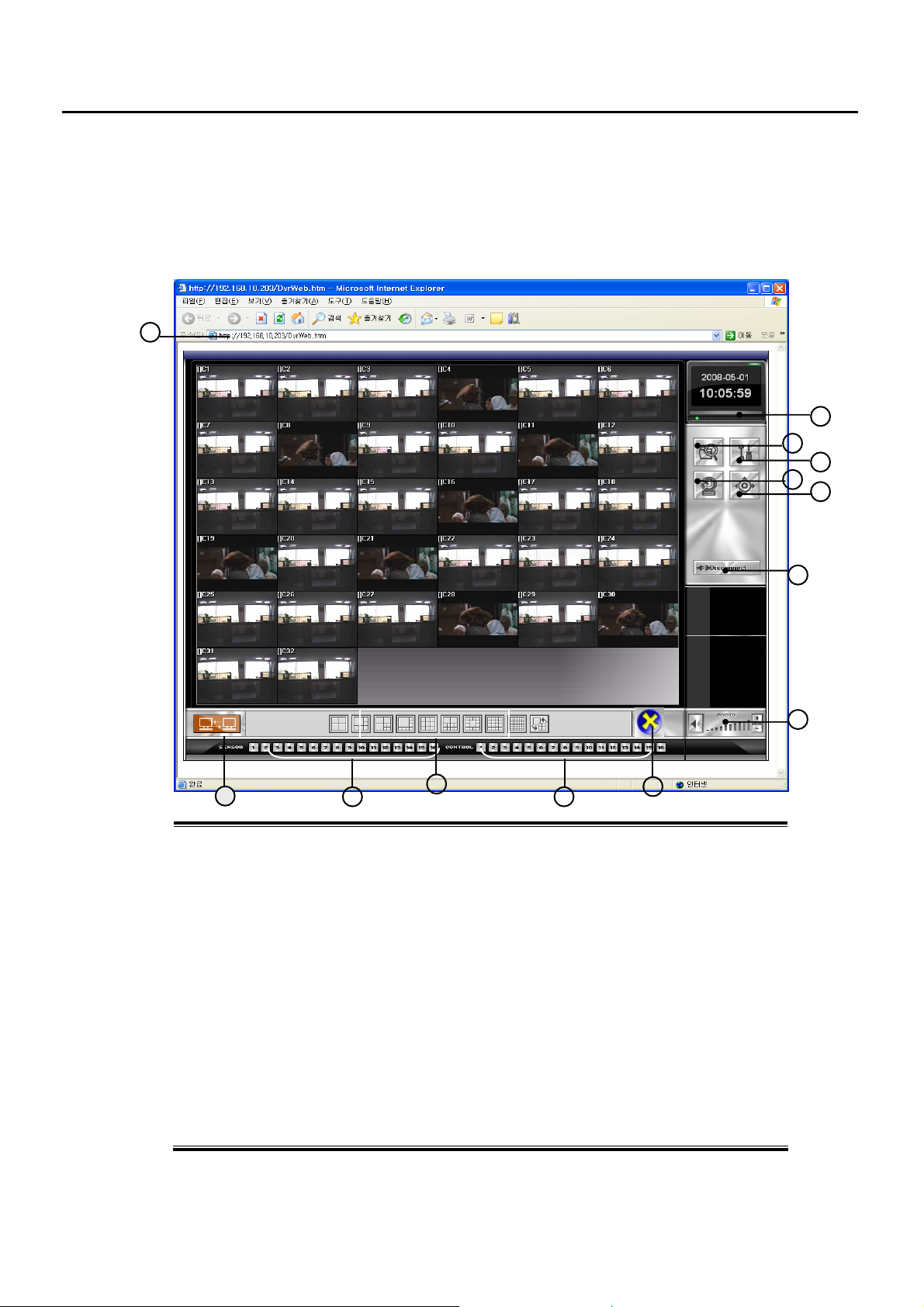
You can monitor as well as control NVR or DVR in remote place by just input its IP address in MS Internet
Explorer.
7.2.1 Connection & Monitoring of Web Client
1
12
11
1. IP Address Line – Input the IP address of NVR, DVR you want to connect in this Internet
Explorer address line and ENTER. Please click YES when it inquire you of Software Installation.
2 Day and Time Display – display present Time
3 Search Button – You can search recorded data of NVR or DVR
4 Setup Button – You can set Camera, Recording Frame, Recording Mode, Backup Schedule,
System Setup and so on
5 Backup Button – manually backup the recorded data to your client PC
6 PTZ Button – display PTZ Control Window
7 Connect/Disconnect Button – connect or disconnect with NVR or DVR
8 Audio Volume Control – Turn on Audio or control its volume
9 Control Output Status Display – Display status of Control Outputs connected to the DVR
10 Screen Division Selection – select Monitoring in various Screen mode
11 Sensor Status Display – display Sensor Status connected to the DVR or NVR
12 Network Status Display – display the connection status. Color changed in Orange
13 DirectX Option – when image does not appear properly, click this icon
1
13
2
3
4
5
6
7
8
- 57 -
Page 58

Chapter
8
C
C
M
M
S
S
((CCeennttrraall MMoonniittoorriinngg SSyysstteemm))
8.1 CMS Installation
8.2 CMS Windows
8.3 CMS Start
Group/Site Add
Connect to the Site
Activate Site Menu (Setup, Search, Backup)
8.4 CMS Menu
8.4.1 PTZ Control
8.4.2 Event/Log List
8.4.3 CMS Setup
Options Registration
User Registration
CMS Version Information
8.4.4 Healthy List
8.5 E-MAP Program
8.5.1 Installation
8.5.2 MAP Edit
8.5.3 Camera Icon Add
8.5.4 Camera Integration with Icon on E-MAP
- 58 -
Page 59
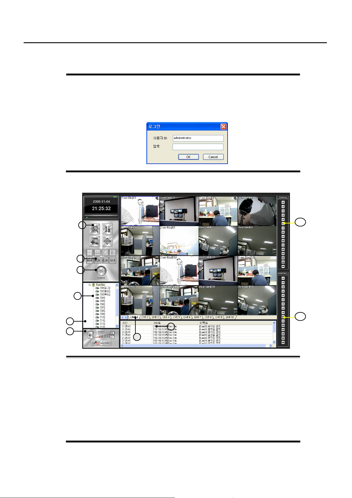
8.1 CMS Installation
1) double Click CMSSETUP.EXE file of CMSSETUP folder
2) click YES or NEXT following Installation Wizard
3) CMS Icon will appear on Desktop
4) double click the CMS icon
* For your reference, Default ID is administrator without password. Click OK
8.2 CMS Window
1
2
3
4
5
6
1 Menu – Search, Setup, Event & Log List, PTZ Control
2 Screen Division – choose one of various Screen Division
3 Exit – click to Logoff, close Program
4 Group / Site – add, edit Group or Site
Double Click the Site Name for Connection
Right Click at the Site Name or Camera Window for Setup, Backup, Search Menu
5 Audio– Turn on/off Audio, Volume Control
6 Microphone – turn on/off Microphone, Volume Control
7 NVR Site Sheet – each Sheet shows each Site of NVR connected
8 Event List – display Event Status coming from NVR (need to set it in CMS Setup – Option)
9 Sensor Status Display – display Sensor Status
10 Control Status and Control – display Control Status connected to the NVR and control it
9
10
8
7
- 59 -
Page 60
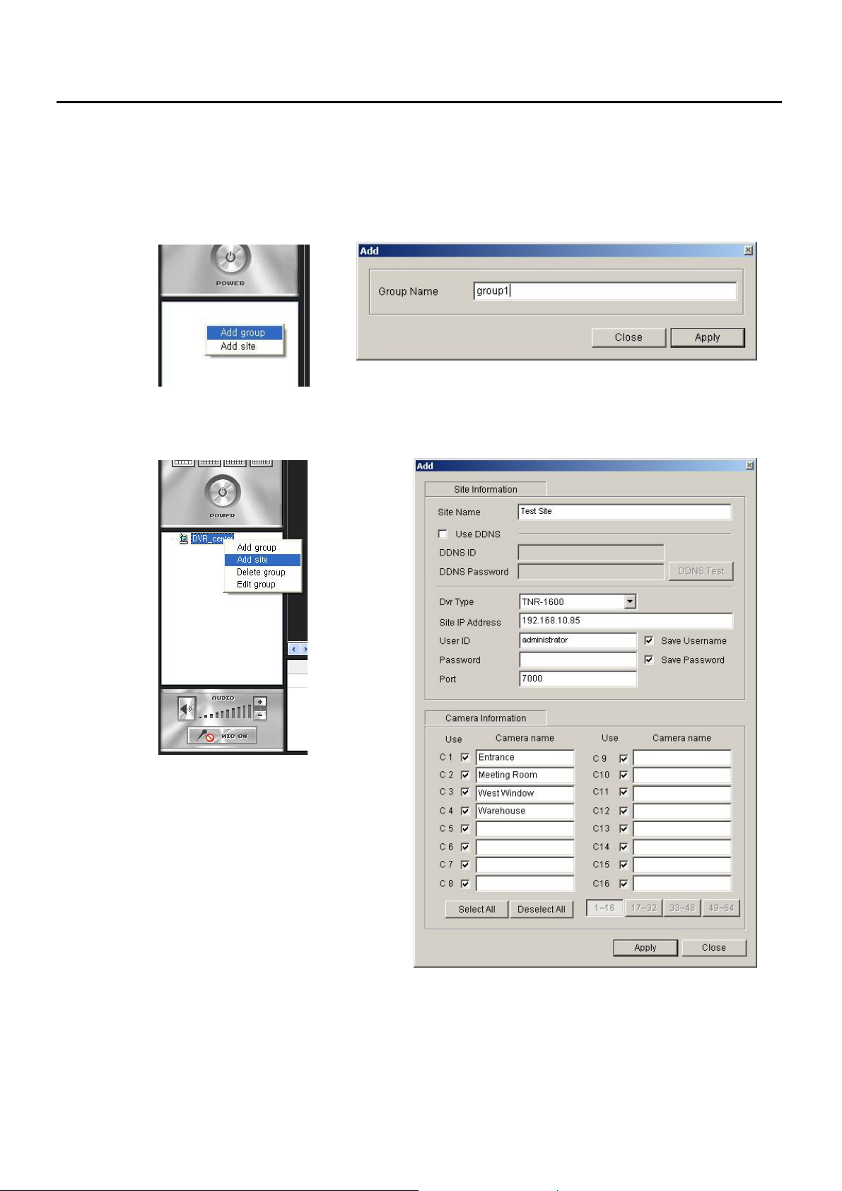
8.3 CMS Start
GROUP Add
■
Right Click at Group/Site Bar. Select Add Group
SITE Add
■
- make SITE NAME for your reference
- In case the NVR, DVR is using DDNS,
click “USE DDNS” and input DDNS ID
and its Password
- Select Model Number of DVR or NVR
* if the unit is not using DDNS service, input
its Site IP Address
- Input User ID and Password – same as that
of NVR or DVR
Default: ID: administrator with no password
- Input PORT number (default port: 7000)
* In case the DVR or NVR is using a Router, users need to set this Router to port 7000 forwarded before
- Click the Camera you want to connect and write its information for your reference
- Click APPLY and Close
Each GROUP can has several SITE of NVR, DVR
Right Click at the GROUP name and select Add SITE
- 60 -
Page 61
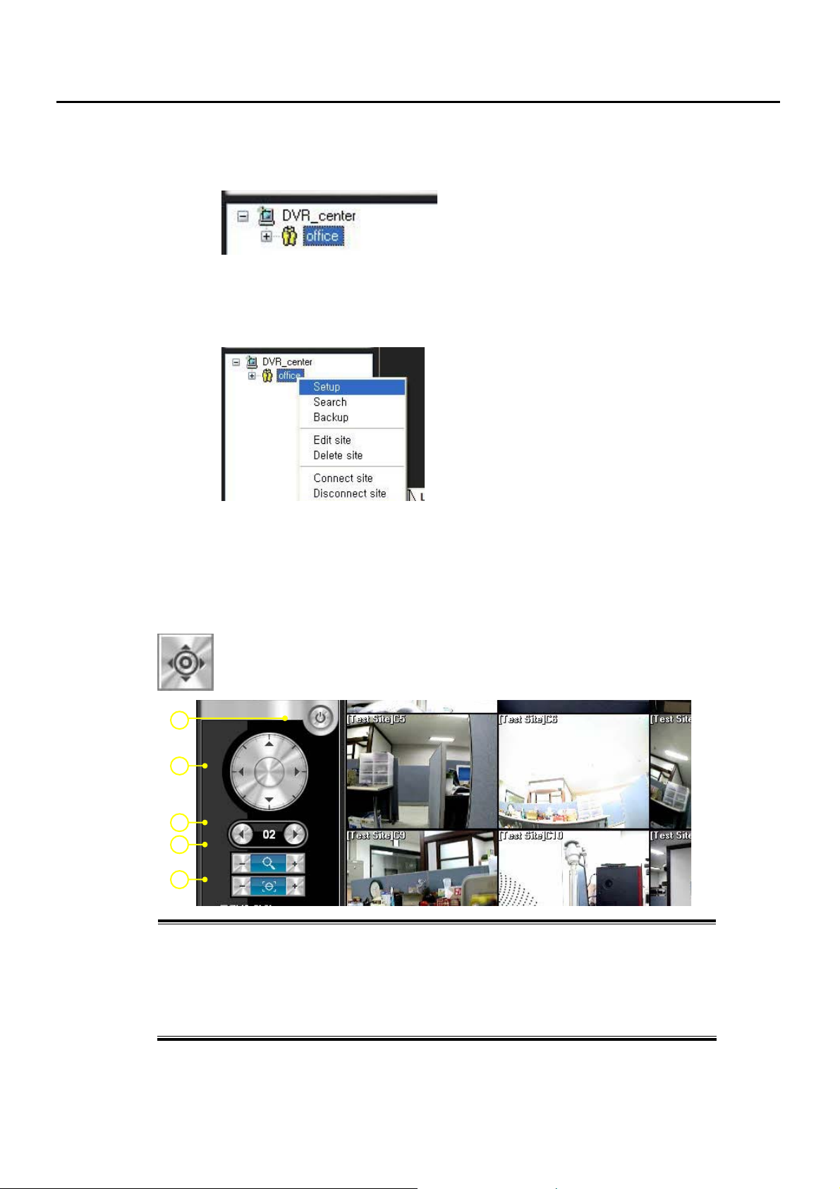
■ Connect to the SITE
DOUBLE CLICK the SITE NAME or right click and select “CONNECT”
Activate SITE Menu
■
* Right Click at the SITE name OR
* Right Click at Camera Window during Monitoring
8.4 CMS MENU
8.4.1 PTZ Control
1
2
3
4
5
1 Exit – go back to Main Menu
2 PTZ Control – Pan / Tilt / Zoom Control
3 Camera Selection – Select Camera clicking ◀ or ▶
4 Zoom In/Out – Zoom Out ( - ), Zoom In ( + )
5 Focus Control – Adjust the focus if necessary
control remote PTZ Camera which is connected to the DVR or NVR
* Setup – NVR, DVR setup
* Search – NVR, DVR search
* Backup – NVR, DVR data backup to CMS PC
* Edit Site – Site Information edit
* Delete Site – Delete this Site
* Connect Site – connect to the NVR or DVR
(or just double click the SITE NAME)
* Disconnect Site – terminate connection
- 61 -
Page 62
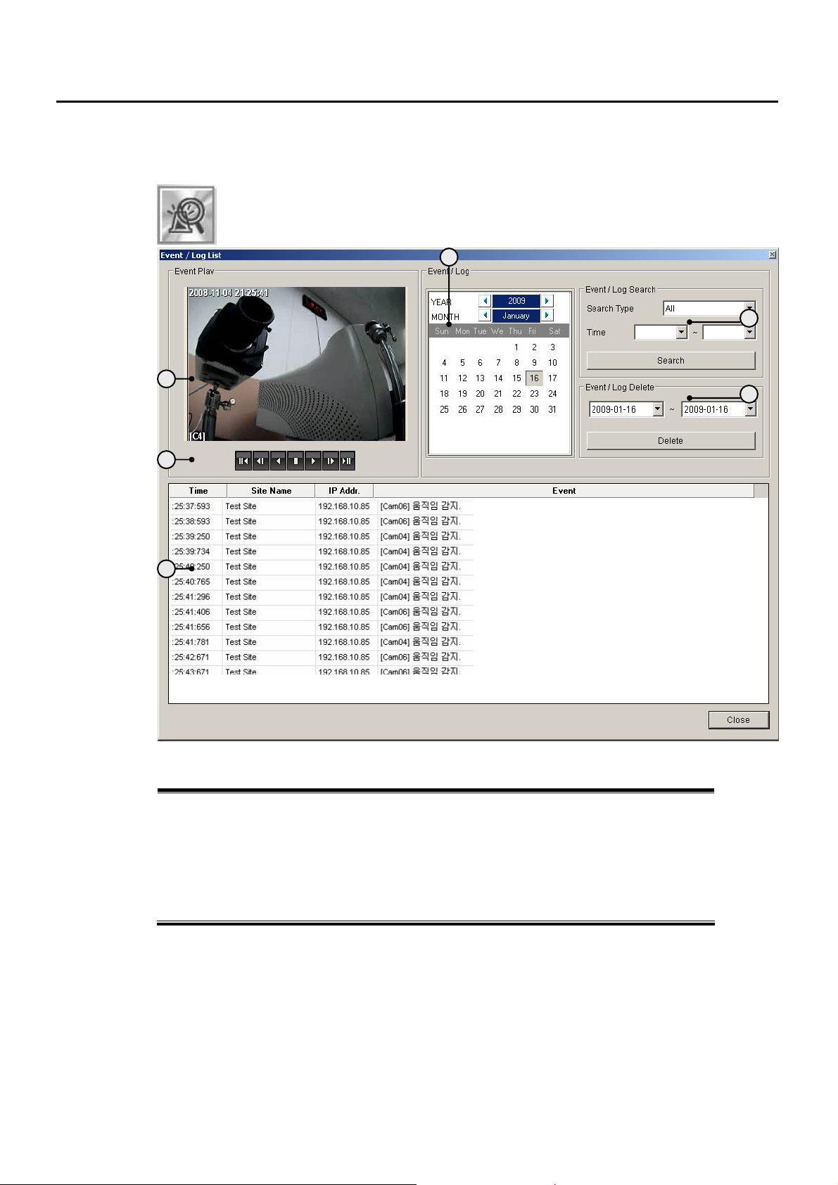
8.4.2 Event & Log List
Event and Log Data Search coming from NVR, DVR
You need to activate CMS LOG WRITE in CMS Setup – Option Registration (next page)
1
2
3
1 Event Monitoring Window – playback Event from Event/Log List
2 Playback Buttons – Reverse, Playback, Playback by frame, etc.
3 Event List – show Events with its type, Site, Camera and IP address information
4 Calendar – Select a day when you want to view Event List
5 Event Type Select – you can select Event Type which you want to search
6 Event/Log Delete – Delete Event/Log Information
4
5
6
- 62 -
Page 63
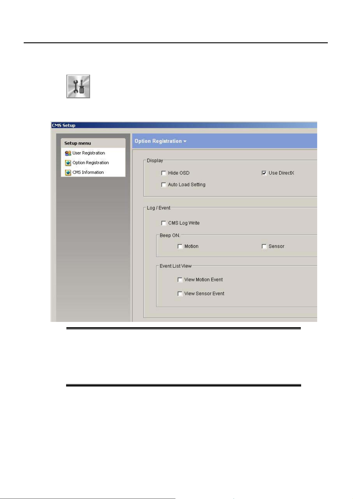
8.4.3 CMS Setup
■ Option Registration
1 DISPLAY
Hide OSD – hide OSD MENU from CMS Monitoring Windows
Auto Load Setting – select to auto save CMS Monitoring Setting
2 LOG/EVENT
CMS LOG Write – forward the Event information of NVR to CMS
3 BEEP Sound – integrate BEEP sound with MOTION detection or Sensor detection of DVR,
NVR
4 Event List View – Show Event List on bottom of CMS Monitoring Windows
CMS User Registration, Option Registration and CMS Upgrade Setup
* for DVR, NVR remote setup, right click Mouse at the Site Name or Camera Window
- 63 -
Page 64
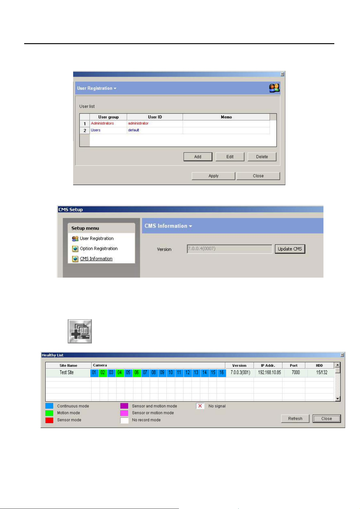
■ CMS USER Registration
CMS Version Information and Upgrade
■
8.4.4 Healthy List
Show the Status of DVR and NVR connect with Site Name, IP Address, HDD storage as
well as each Camera Recording Mode.
- 64 -
Page 65
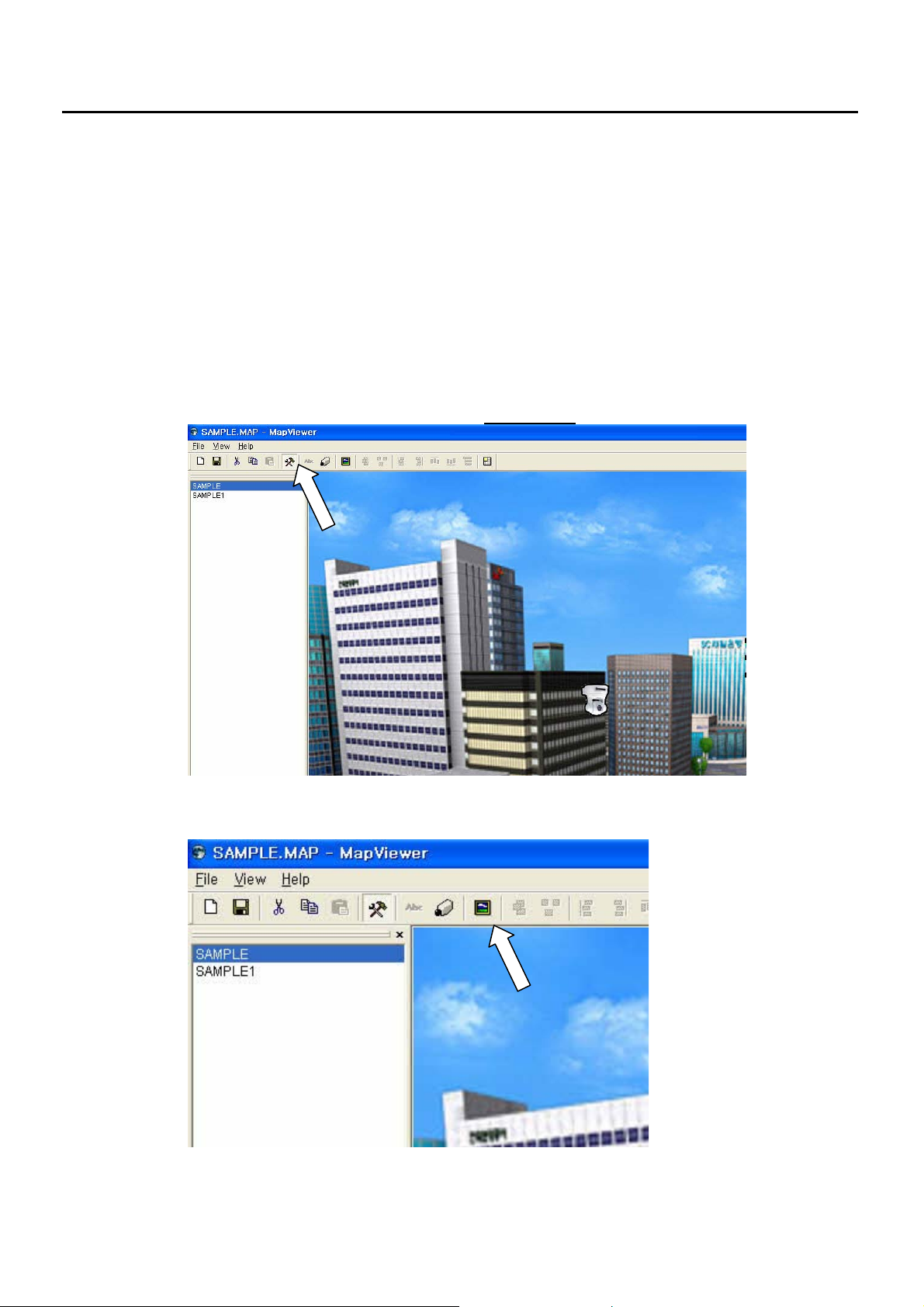
8.5 E-MAP Program
8.5.1 CMS MAP Installation
1) double click CMSMAPsetup.exe and follow the instruction
2) CMSMAP icon will appear on DESKTOP after installation
8.5.2 CMS MAP EDIT
1) Double click CMSMAP icon
2) To see the SAMPLE map, double click the SAMPLE or SAMPLE1.
z Input MAP image file
1) Click the HAMMER icon on the menu bar to be in EDIT mode.
2) click the MAP icon on the menu bar to input a map.
- 65 -
Page 66
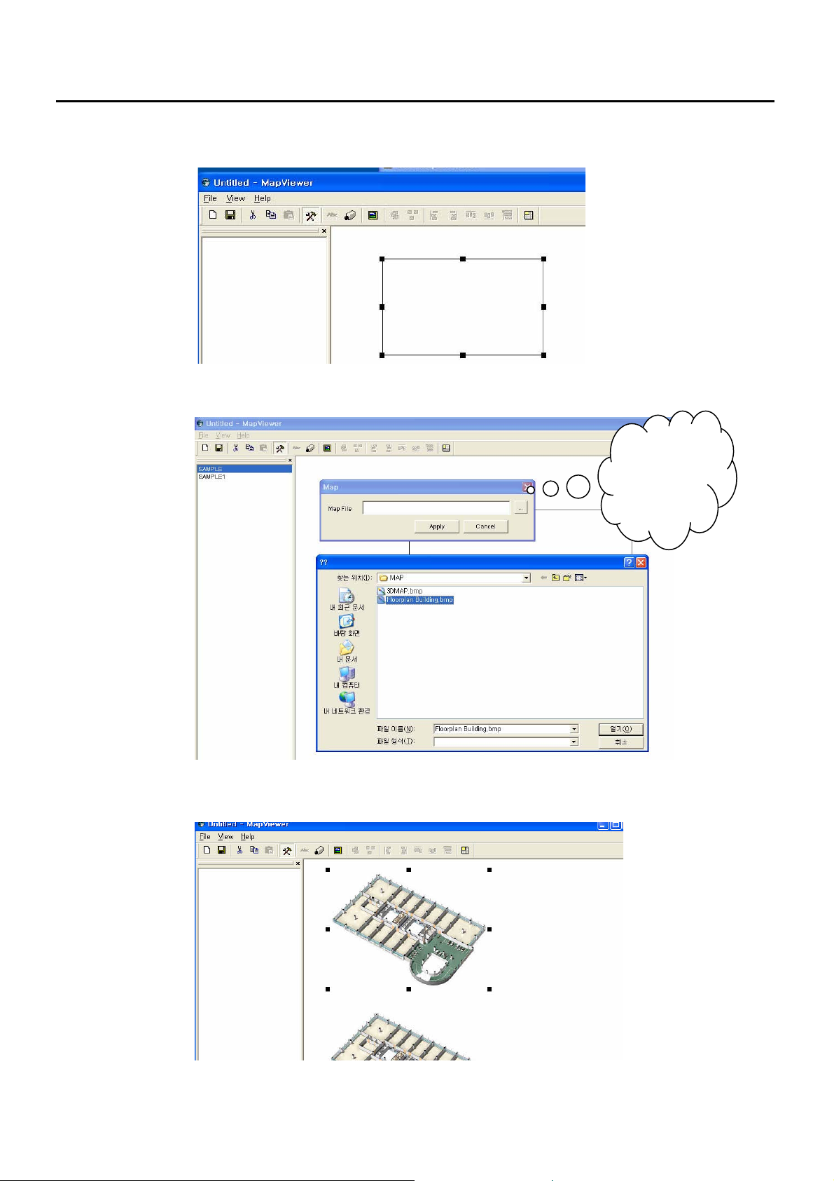
3) drag with a mouse and make a squre.
4) to find a MAP image, put the mouse pointer in the square and double click
5) You can put as many map images on the window as you wish and you can change their size by drag a
mouse
Click this
button to find
the folder
- 66 -
Page 67
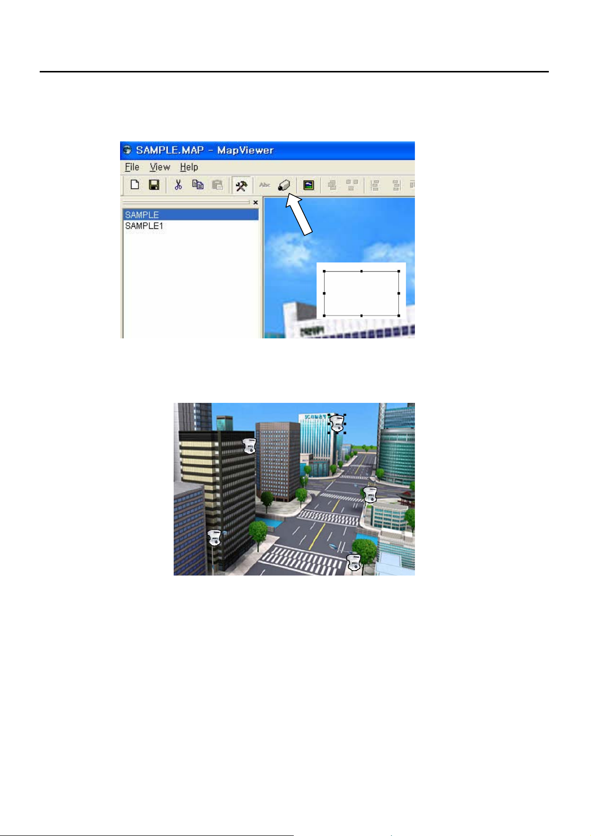
8.5.3 CAMERA ICON add on the MAP image
1) Click the Camera icon the menu bar and drag a mouse on the MAP image
2) Camera icon will appear. You can duplicate them as many as you wish – right click Mouse on the
Camera icon and select DUPLICATE
Mouse Right Click Menu on Camera Icon or MAP image
1) Cut: delete
2) Copy
3) Duplicate: make a copy
4) Up: put the camera icon (or map image) to the front of previous one.
5) Down: put the camera icon (or map image) to the back of next one
6) To Front: put the camera icon (or map image) to the first
7) To Back: put the camera icon (or map image) to the last
8) Properties:
- Map Image: folder location for the map image file
- Camera Icon: DVR, Camera network information
- 67 -
Page 68
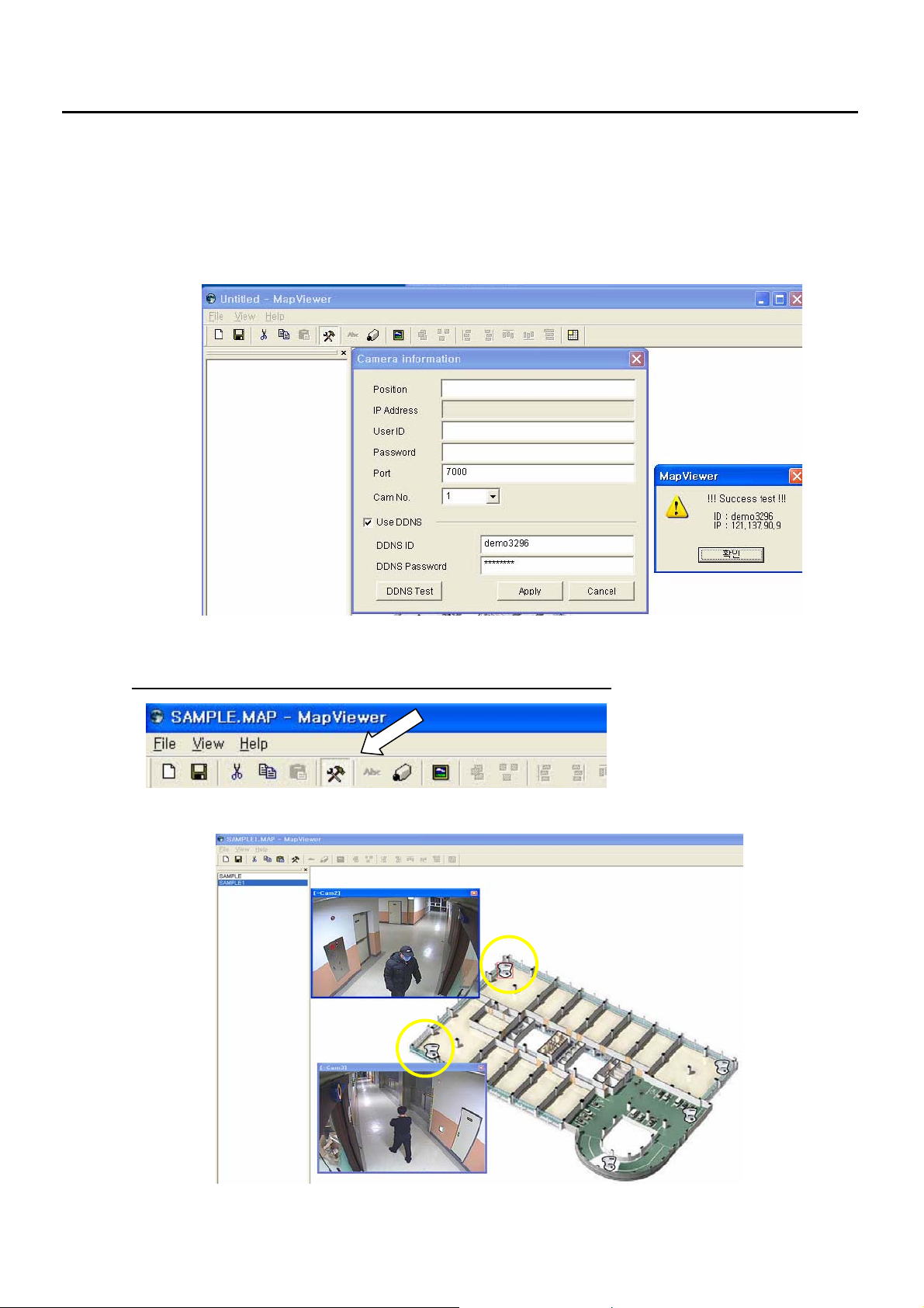
8.5.4 CAMERA Integration with ICON on MAP
Integrating Camera Icon with Camera View
1) Double click the Camera icon OR right click and select “properties”.
2) Camera Information Menu will pop-up.
Input the Camera information you want to connect.
In case DDNS use, input “Port”, “Camera Number” and DDNS ID and PW before click APPLY.
You can click “DDNS Test” to see whether its information or network is OK
To come out from “EDIT” mode, click the Hammer icon on the menu bar.
1) Double click the Camera icon and then relevant Camera View will appear
- 68 -
Page 69
9 Save E-MAP
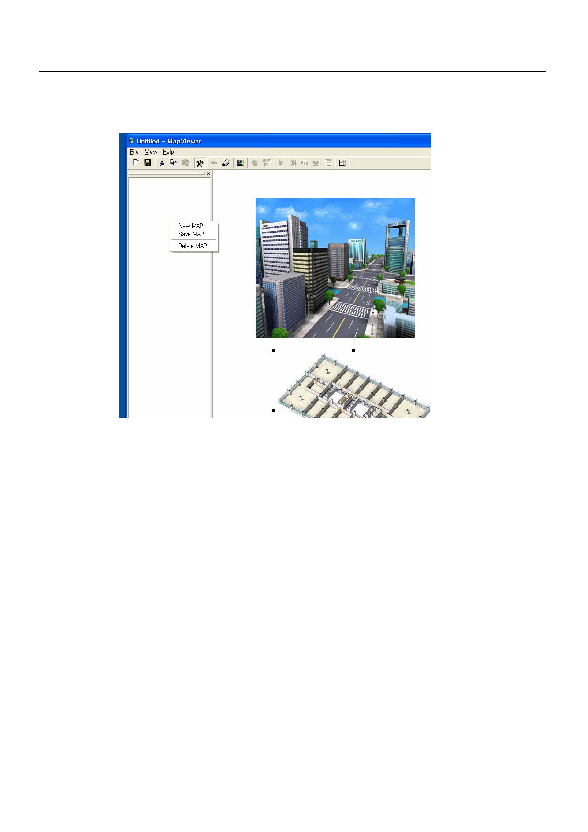
1) You can save the map as a .MAP file.
Right click on the left Window and select “Save MAP”.
If you select “New MAP”, those things you just made will disappear without warning.
10 Remark
As this CMS-MAP program is still development status, your kind comment will be highly appreciated. Please
feel free to comment us.
- 69 -
 Loading...