

EZ Digital FG-7005C Operation Manual
Bench-top Instrument
FG-7005C
Sweep Function Generator
Operation Manual
88 88

WARRANTY
Warranty service covers a period of one year from the date of original purchase.
In case of technical failure within one year, our service center or sales outlet free of
charge will provide repair service.
We charge customers for repair after the one-year warranty period has been
expired. Provided that against any failure resulted from the user’s negligence,
natural disaster or accident, we charge you for repairs regardless of the warranty
period.
For more professional repair service, be sure to contact our service center or sales
outlet.

Introduction
Thank you for purchasing a EZ product. Electronic measuring instruments
produced by EZ Digital are high technology products made under strict quality
control. We guarantee their exceptional precision and utmost reliability. For proper
use of the product, please read this operation manual carefully.
Digital Co., Ltd.
Note
1. To fully maintain the precision and reliability of the product use it within the range
of standard setting( temperature 10 °C~35 °C, humidity 45%~85%)
2. After turning of power, please allow a pre-heating period of as long as some 10
minutes before use.
3. This equipment should be used with a triple line power cord for safety.
4. For quality improvement the exterior design and specification of the product can
be changed without prior notice.
5. If you have further questions concerning use, please contact the EZ Digital
service center or sales outlet
Safety Summary
Please take a moment to read these operating instructions thoroughly and
completely before operating this instrument. Pay particular attention to WARNINGS
used for conditions and actions that pose hazard to the user and CAUTIONS used
for conditions and actions that may damage the instrument.
Always to inspect the instrument and other accessories for any sign of damage
or abnormality before every use.
Never ground yourself and keep your body isolated from ground.
Never touch exposed wiring, connections or any live circuit conductors.
Do not install substitute parts or perform any unauthorized modification to the
instrument.
Use caution when working above 60V DC or 30V AC rms. Such voltages pose
a shock hazard.
Remember that line voltage is present on some power input circuit points such
as on-off switches, fuse, power transformers, etc., even when the equipment is
turn off.
Also, remember that high voltage may appear at unexpected points in defective
equipment.

CONTENTS
1. PRODUCT DESCRIPTION ----------------------------------------------------------- ( 2 )
1-1. Introduction ----------------------------------------------------------------- ( 2 )
1-2. Technical Specifications ------------------------------------------------- ( 2 )
1-3. Equipment Ratings -------------------------------------------------------- ( 3 )
1-4. Supplied Accessories ---------------------------------------------------- ( 4 )
2. INSTALLATION -------------------------------------------------------------------------- ( 5 )
2-1. Initial Inspection ----------------------------------------------------------- ( 5 )
2-2. Connecting Ac Power ---------------------------------------------------- ( 5 )
2-3. Cooling And Ventilation -------------------------------------------------- ( 5 )
2-4. Position ---------------------------------------------------------------------- ( 5 )
2-5. Warming-Up ---------------------------------------------------------------- ( 5 )
3. OPERATION ------------------------------------------------------------------------------ ( 6 )
3-1. Controls, indicators and connectors ---------------------------------- ( 6 )
3-2 Operating instruction -------------------------------------------------- ( 8 )
3-3. Use As Function Generator --------------------------------------------- ( 8 )
3-4. Use As Pulse Generator ------------------------------------------------- ( 11 )
3-5. TTL/CMOS Output -------------------------------------------------------- ( 12 )
3-6. Use As FM Signal Generator ------------------------------------------- ( 13 )
3-7. External Control Of VCF ------------------------------------------------- ( 14 )
3-8. Programmed Frequency Selection ------------------------------------ ( 15 )
3-9. Use As Sweep Generator ----------------------------------------------- ( 15 )
3-10. Use As Externally Controlled Sweep Generator ----------------- ( 16 )
3-11. Use As External Frequency Counter -------------------------------- ( 16 )
4. MAINTENANCE ------------------------------------------------------------------------- ( 17 )
4-1. Fuse Replacement -------------------------------------------------------- ( 17 )
4-2. Adjustment And Calibration --------------------------------------------- ( 17 )
4-3. Cleaning and Decontamination ---------------------------------------- ( 17 )
5. OTHERS ----------------------------------------------------------------------------------- ( 18 )
5-1. Introduction ----------------------------------------------------------------- ( 18 )
5-2. Troubleshooting By Signal Substitution ------------------------------ ( 18 )
5-3. Troubleshooting By Signal Tracing ----------------------------------- ( 18 )
5-4. Amplifier Overload Characteristics ------------------------------------ ( 19 )
5-5. Amplifier Performance Evaluation Using Square Waves ------- ( 19 )
5-6. Testing Speakers And Impedance Networks ----------------------- ( 22 )
5-7. Digital Frequency Selection --------------------------------------------- ( 23 )
5-8. Additional Applications --------------------------------------------- ( 23 )
1. PRODUCT DESCRIPTION

1-1. Introduction
This instrument is the Most Versatile Signal Source used as FUNCTION
GENERATOR, SWEEP GENERATOR, PULSE GENERATOR and a FREQUENCY
COUNTER, offering a wide range of applications in both analog and digital electronics such as engineering, manufacturing, servicing, education and hobbyist fields.
VCF(voltage controlled frequency) produces precision sine, square and triangle
waves over the 0.05 Hz to 5 MHz for sub-audible, audio, ultrasonic and RF
applications. A continuously variable DC offset allows the output to be injected
directly into circuits at the correct bias level.
Variable symmetry of the output waveforms converts the instrument to a pulse
generator capable of generating rectangular waves or pulses, ramp or sawtooth
waves and skewed sine waves of variable duty cycle. The sweep generator offers
linear sweep with variable sweep rate and sweep width up to 100:1 frequency
change. The frequency response of any active or passive device up to 5 MHz can
be determined.
1-2. Technical Specifications
OUTPUT CHARACTERISTICS
Waveforms : Sine, Square, Triangle, Ramp, Pulse, Sawtooth,
TTL/CMOS Leveled Square, DC
Frequency Range : 0.05 Hz to 5 MHz in 7 Range(1,10,100,1K,10K,100K,1M)
Frequency Accuracy : ±5% (1,10,100,1K,10K,100K,1MHz Range ) (Full Scale)
Output Level : 20 Vp-p in open circuit, 10 Vp-p into 50 Ω Load
Output Impedance : 50 Ω ±5%
Attenuator : 20 dB fixed and continuously variable
WAVEFORM CHARACTERISTICS
Sine wave -Flatness : ± 2.5V to 5 MHz
-Distortion : Less than 1% at 0.5 Hz to 100 KHz
Square wave -Rise and Fall Time : Less than 25 nS
Triangle wave -Linearity : More than 99% at 0.2 Hz to 100 KHz
TTL Output -Rise and Fall time : Less than 25 nS
-Output Level : TTL Level(H
2.4V, L 0.4V)
CMOS Output -Rise and Fall Time : Less than 150 nS(Max. Out)
(DC – to 2MHz) -Output Level : 4V to 15V ± 1V, Variable
DUTY RATIO : 1:1 to 10 : 1
SWEEP FUNCTION CHARACTERISTICS
Mode : Linear
Width : Variable from 1 : 1 to 100 : 1
Rate : 0.5 Hz to 50 Hz (20 mS to 2 S)
External VCF Input : Input Voltage : 0 to 10 V
Input Impedance : Approx. 10 KΩ
FREQUENCY COUNTER CHARACTERISTICS
Display : 6 digit green LED, Gate time, MHz, KHz, Hz, mHz.
Frequency Range : 500 mHz to 50 MHz With Auto Range.
Accuracy : ±Time base Error ± 1 count
Time base : 10 MHz
Input Sensitivity : 100 mVrms
Max. Input Voltage : 250 Vp-p
DIMENSION AND WEIGHT
Dimension : 255(W)x 255(D) x90(H)mm
Weight : Approx. 2.0Kg
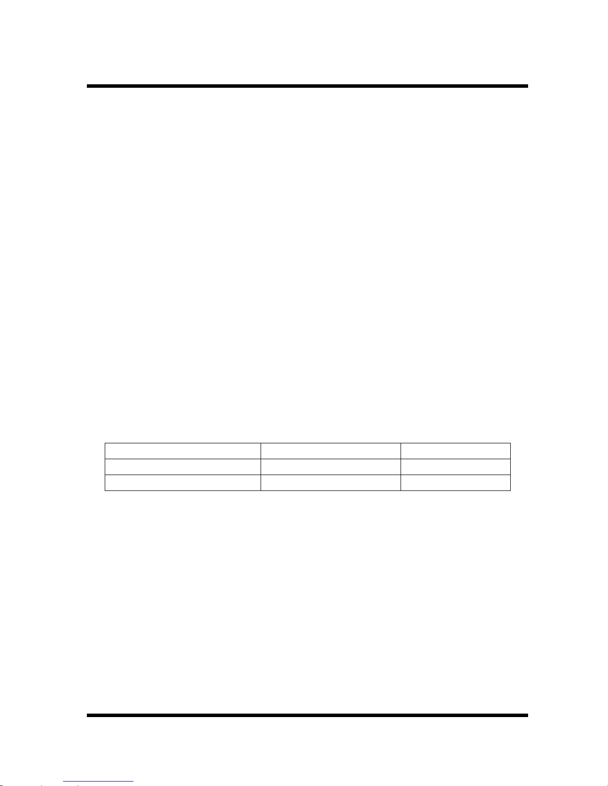
1-3. Equipment Ratings
InputVoltage Fuse PowerMax.
103126VAC(50/60Hz) F0.5A250V 15W
206252VAC(50/60Hz) F0.25A250V 15W
Operating Environment
TEMPERATURE : 0 ° C to + 40 ° C
HUMIDITY :up to 85% to 40° C without temperature extremes
causing condensation within the instrument.
Storage Environment
TEMPERATURE : -20° C to +70° C
HUMIDITY : below 85% RH
Insulation Category II : Portable equipment of local level.
Pollution Degree : 2
Protection to IEC 529 : Ordinary

1-4. Supplied Accessories
User’s Manual ---------------------------------------------------------------------------- 1
BNC Cable ------------------------------------------------------------------------------ 1
Power Cord ------------------------------------------------------------------------------ 1
Spare Fuse ------------------------------------------------------------------------------- 1
specifications are subject to change without notice.

2. INSTALLATION
2-1. Initial Inspection
This instrument was carefully inspected both mechanically and electrically before
shipment. It should be physically free of damage. To confirm this, the instrument
should be inspected for physical damage in transit. Also, check for supplied
accessories.
2-2. Connecting AC Power
This instrument requires AC 230V/115V,50-60Hz power through 3-conductor ac
power cable to be fit into three-contact electrical outlet to secure grounding.
If forced to use 2-conductor cable, use ground terminal in rear panel for grounding
instrument.
CAUTION
THIS INSTRUMENT IS SET TO AC 230V. BEFORE POWERING ON THIS
INSTRUMENT, MAKE SURE THE VOLTAGE OF THE POWER SOURCE IS AC
230V. IN CASE OF AC115V, SWITCH SHOULD BE SELECTED DOWN TO 115V
POSITION.
2-3. Cooling And Ventilation
No special cooling and ventilation is required. However, the instrument should be
operated where the ambient temperature is maintained.
2-4. Position
This instrument is built as a bench-type instrument with rubber feet and tilt stand in
place. Stand-up angle can be adjusted by rotating angle of carrying handle.
2-5. WARMING-UP
Allow more than 20 minutes for the unit to warm up so that it is stabilized and ready
for use.
3. OPERATION
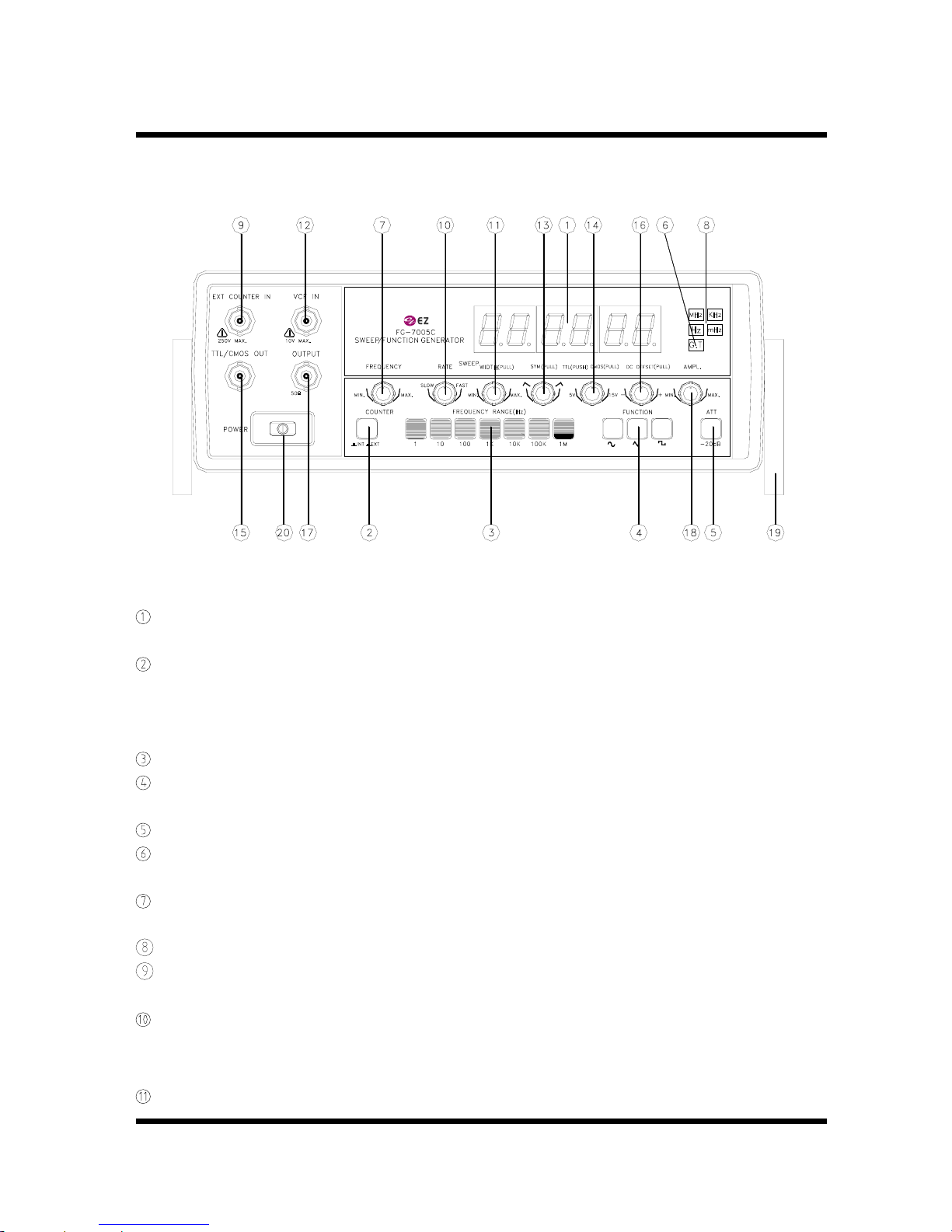
3-1. Controls, indicators and connectors
FIG 1. FRONT PANEL OPERATOR’S CONTROLS
LED DISPLAY. Displays Internal Or External
Frequency.
INTERNAL/EXTERNAL SWITCH. PUSH IN : External Frequency
Counter.
PUSH OUT: Internal Frequency
Counter.
RANGE SWITCHES. Frequency Range Selector.
FUNCTION SWITCHES. Select Sine wave, Triangle Wave Or
Square Wave Output.
ATTENUATOR. Selects Output Level By -20 dB.
GATE TIME INDICATOR. Gate Time Is Selected Automatically By
Input Signal.
FREQUENCY DIAL. Controls Output Frequency In Selected
Range.
MHz, KHz , Hz, mHz INDICATOR. Indicates Unit Of Frequency.
EXTERNAL COUNTER INPUT BNC. Used As An External Frequency
Counter.
SWEEP RATE CONTROL. On-Off Switch For Internal Sweep
Generator, Adjusts Sweep Rate Of
Internal Sweep Generator.
SWEEP WIDTH CONTROL. Pullout And Adjusts Magnitude Of
 Loading...