

EZ Digital FC-3000, FC-7015, FC-7150, FC-7150U, FC-7015U Operation Manual

WARRANTY
Warranty service covers a period of one year from the date of original purchase.
In case of technical failure within one year, our service center or sales outlet free of
charge will provide repair service.
We charge customers for repair after the one-year warranty period has been expired.
Provided that against any failure resulted from the user’s negligence, natural disaster
or accident, we charge you for repairs regardless of the warranty period.
For more professional repair service, be sure to contact our service center or sales
outlet.

Introduction
Thank you for purchasing a EZ product. Electronic measuring instruments produced by
EZ Digital are high technology products made under strict quality control. We
guarantee their exceptional precision and utmost reliability. For proper use of the
product, please read this operation manual carefully.
EZ Digital Co., Ltd.
Note
1. To fully maintain the precision and reliability of the product use it within the range of
standard setting( temperature 10 °C~35 °C, humidity 45%~85%)
2. After turning of power, please allow a pre-heating period of as long as some 30
minutes before use.
3. This equipment should be used with a triple line power cord for safety.
4. For quality improvement the exterior design and specification of the product can be
changed without prior notice.
5. If you have further questions concerning use, please contact the EZ Digital service
center or sales outlet
Safety Summary
Please take a moment to read these operating instructions thoroughly and completely
before operating this instrument. Pay particular attention to WARNINGS used for
conditions and actions that pose hazard to the user and CAUTIONS used for
conditions and actions that may damage the instrument.
Always to inspect the instrument and other accessories for any sign of damage or
abnormality before every use.
Never ground yourself and keep your body isolated from ground.
Never touch exposed wiring, connections or any live circuit conductors.
Do not install substitute parts or perform any unauthorized modification to the
instrument.
Use caution when working above 60V DC or 30V AC rms. Such voltages pose a
shock hazard.
Remember that line voltage is present on some power input circuit points such as
on-off switches, fuse, power transformers, etc., even when the equipment is turn
off.
Also, remember that high voltage may appear at unexpected points in defective
equipment.
Test Equipment Depot - 800.517.8431 - 99 Washington Street Melrose, MA 02176
FAX 781.665.0780 - TestEquipmentDepot.com
3

CONTENT
1. PRODUCT DESCRIPTION
1-1. Introduction ------------------------------------------------------ 5
1-2. Technical Specifications -------------------------------------- 6
1-3. Equipment Ratings --------------------------------------------- 9
1-4. Supplied Accessories ------------------------------------------ 10
2. INSTALLATION
2-1. Initial Inspection ------------------------------------------------- 10
2-2. Connecting AC Power ----------------------------------------- 10
2-3. Cooling and Ventilation ---------------------------------------- 10
2-4. Position ------------------------------------------------------------ 10
2-5. Warming-Up ------------------------------------------------------ 10
3. OPERATION
3-1. Controls, indicators and connectors ------------------------ 11
3-2. Operating instruction ------------------------------------------- 17
3-3. Frequency Measurements ------------------------------------- 18
3-4. Period Measurements ------------------------------------------ 19
3-5. Total Measurements -------------------------------------------- 19
3-6. RPM measurement ---------------------------------------------- 19
3-7. Time interval measurement(A-B)----------------------------- 19
3-8. Ratio Measurement (A/B)-------------------------------------- 20
4. MAINTENANCE
4-1. Fuse Replacement ---------------------------------------------- 21
4-2. Adjustment and Calibration ----------------------------------- 21
4-3. Cleaning and decontamination ------------------------------- 21
5. OTHERS
5-1. BNC Cable Considerations ----------------------------------- 22
5-2. Use of Attenuator probes ------------------------------------- 22
5-3. Line Frequency Measurements ------------------------------ 23
1. PRODUCT DESCRIPTION
Test Equipment Depot - 800.517.8431 - 99 Washington Street Melrose, MA 02176
FAX 781.665.0780 - TestEquipmentDepot.com
4

1-1. Introduction
This reciprocal UNIVERSAL(FREQUENCY) COUNTER series are microprocessor
controlled instrument for frequency measurement at high resolution within a short
period of 7 digit display with one second gate time due to uniquely developed LSI as
well as the expanding/reciprocal system. It covers a frequency range from 0.1Hz to 3.3
GHz (FC-3000: 3.3GHz, FC-7150U, FC-7150: 1.5GHz, FC-7015U,FC-7015: 100MHz)
based on 10MHz time base T.C.O (temperature controlled oscillator) and also
featuring,
FC-7150U/FC-7015U Universal Counter
Trigger Function
Time Interval Measurement Function
Frequency Ratio Measurement Function
Common or Separate Input Selection
External Frequency Standard Input with 9 Digits LED Display
Attenuator
Check
Period
Total
Low Pass Filter
Line Filter
FC-3000/FC-7150/FC-7015 Frequency Counter
RPM(Rotation Per Minute) Measuring Function
External Frequency Standard Input with 9 Digits LED Display
Attenuator
Check
Period
Total
Low Pass Filter
Line Filter
A self-test mode is also provided for a quick check of several facts of operation. Each
operating mode can be selected by front panel push button switches with automatic
decimal points and indicators. The high accuracy, sensitivity and versatility of this
counter make it an extremely valuable instrument to the scientist, engineer,
experimenter and communications technician. Light weight and compact size make it
practical for use by the hobbyist or field technicians.
Test Equipment Depot - 800.517.8431 - 99 Washington Street Melrose, MA 02176
FAX 781.665.0780 - TestEquipmentDepot.com
5
1-2. Technical Specifications
INPUT A CHARACTERISTICS
- FREQUENCY RANGE : 0.1Hz to 100MHz (DC Coupled)
30Hz to 100MHz (AC Coupled)
- SENSITIVITY : 0.1Hz to 100MHz: 30mV
- COUPLING : AC or DC Selectable
- IMPEDANCE : 1 M Ω Resistance, Shunted by < 40pF
- ATTENUATOR : x 1 or x 10 Switch Selectable
- LOW PASS FILTER : -3dB Point of 100KHz, Switch Selectable
- TRIGGER LEVEL : + 350mV to - 350mV (PRESET 0V)
(FC-7150U, FC-7015U only)
- SLOPE : Positive or Negative Slope Switch Selectable
(FC-7150U, FC-7015U only)
* NOTE: Trigger error is typically ±0.3% of reading by the number of cycles averaged
for input signals having better than 40dB S/N ratio and greater than 100mV amplitude.
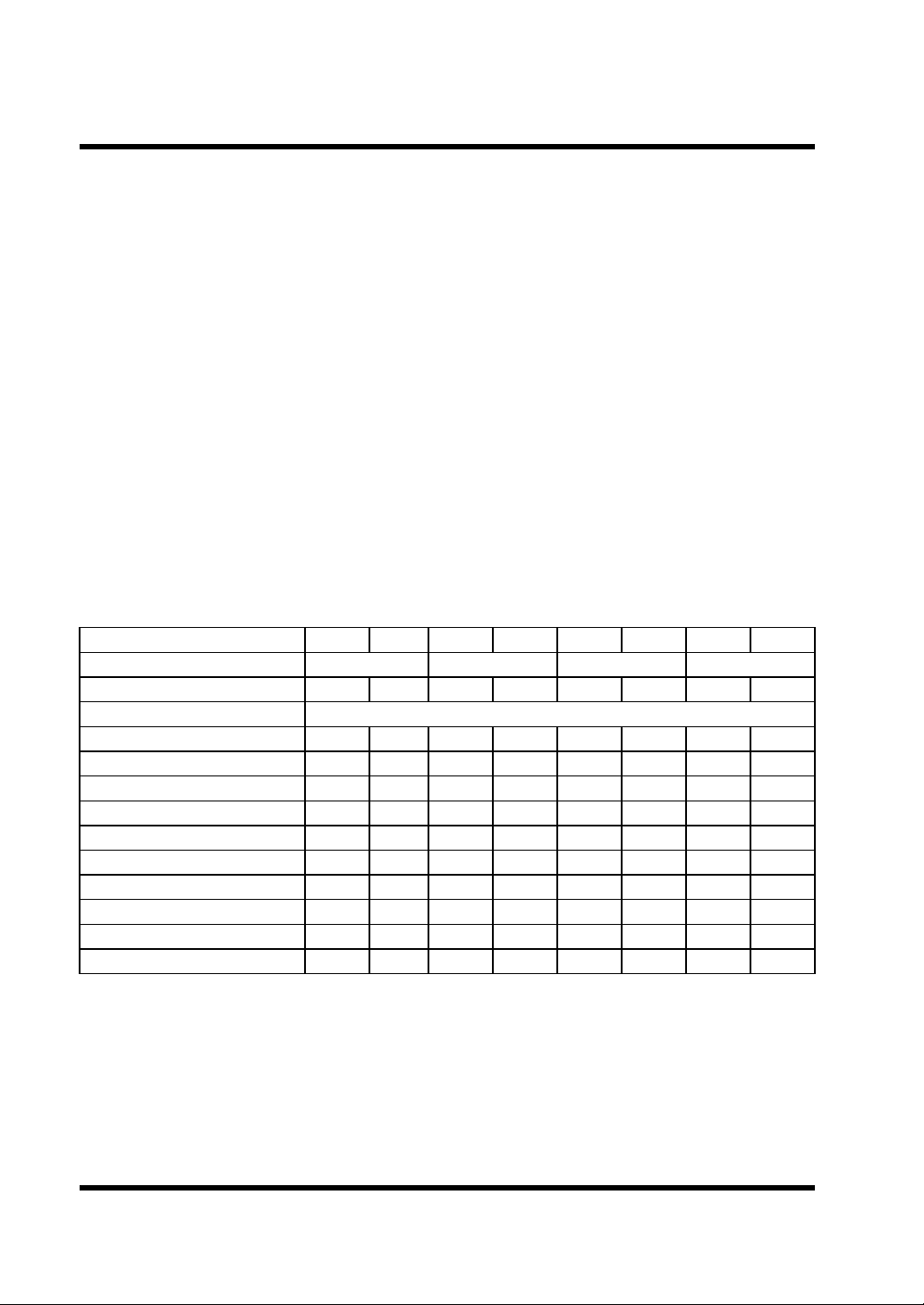
- RESOLUTION AND NUMBER OF DISPLAYED DIGIT
Time Base Selector INT EXT INT EXT INT EXT INT EXT
Gate Time 0.01S 0.1S 1S 10S
Number Of Displayed Digit 5 6 6 7 7 8 8 9
Frequency (Input A,B) RESOLUTION
0.1 Hz-0.99 Hz
1 Hz-9.9 Hz
10 Hz-99 Hz
100 Hz-999 Hz
1 KHz-9.9 KHz
10 KHz-99 KHz
100 KHz-999 KHz
1 MHz-9.9 MHz
10 MHz-99 MHz
100 MHz
10 uHz 1 uHz 1 uHz 0.1 uHz 0.1 uHz 10nHz 10nHz 1nHz
0.1 mHz 10 uHz 10 uHz 1 uHz 1 uHz 0.1 uHz 0.1 uHz 10nHz
1 mHZ 0.1 mHz 0.1 mHz 10 uHz 10 uHz 1 uHz 1 uHz 0.1 uHz
10 mHz 1 mHz 1 mHz 0.1 mHz 0.1 mHz 10 uHz 10 uHz 1 uHz
0.1 Hz 10 mHz 10 mHz 1 mHz 1 mHz 0.1 mHz 0.1 mHz 10 uHz
1 Hz 0.1 Hz 0.1 Hz 10 mHz 10 mHz 1 mHz 1 mHZ 0.1 mHz
10 Hz 1 Hz 1 Hz 0.1 Hz 0.1 Hz 10 mHz 10 mHz 1 mHZ
100 Hz 10 Hz 10 Hz 1 Hz Hz 0.1 Hz 0.1 Hz 10 mHz
1 KHz 100 Hz 100 Hz 10 Hz 10 Hz 1 Hz 1 Hz 0.1 Hz
10 KHz 1 KHz 1 KHz 100 Hz 100 Hz 10 Hz 10 Hz 1 Hz
- ACCURACY : ± Time base Error ± Resolution(Table 1)
- PERIOD RANGE : 10 nS to 10 S
- DISPLAY : n. u. m., Sec with decimal point
- TOTAL RANGE : DC to 30 MHz
- CAPACITY : 0 to 999 999 999
- OVER FLOW : “OF”
7
- RPM RANGE : 6 to 600 x 10
RPM , OVER FLOW : “OF”
Test Equipment Depot - 800.517.8431 - 99 Washington Street Melrose, MA 02176
FAX 781.665.0780 - TestEquipmentDepot.com
6
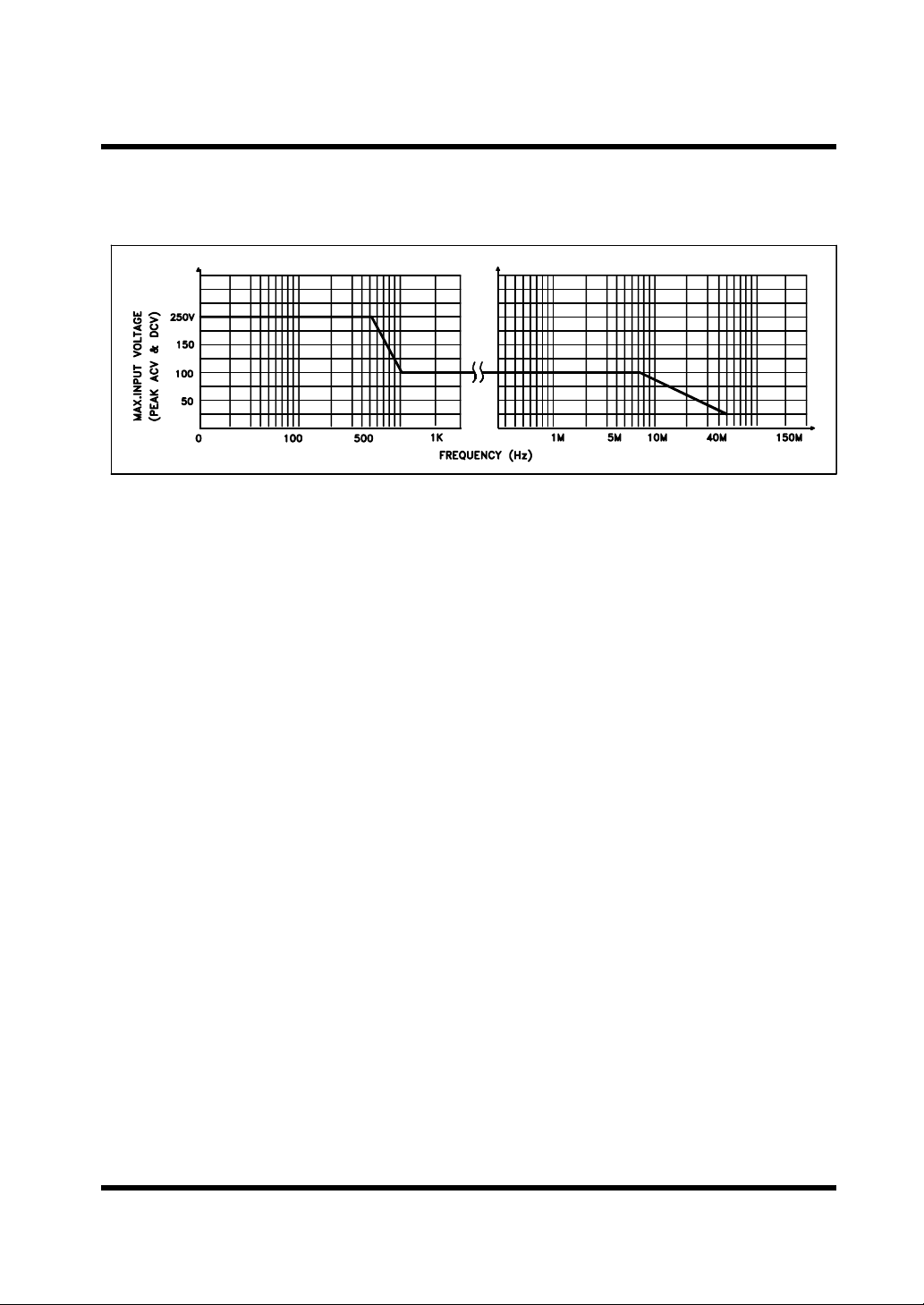
<FC-3000, FC-7150, FC-7015 only>
- MAX. INPUT VOLTAGE LEVEL
FIG 1. MAX. Input Level. (input A,B)
INPUT B. CHARACTERISTICS <FC-7150U, FC-7015U>
- FREQUENCY RANGE : 0.1Hz to 100MHz (DC Coupled)
30Hz to 100MHz (AC Coupled)
- SENSITIVITY : 0.1Hz to 100MHz: 30mV
- COUPLING : AC or DC Selectable
- IMPEDANCE : 1 MΩ Resistance, Shunted by < 40pF
- ATTENUATOR : x 1 or x 10 Switch Selectable
- LOW PASS FILTER : -3dB Point of 100KHz, Switch Selectable
- SLOPE : Positive or Negative Switch Selectable
* Resolution and Number of displayed digit (Table 1): Same as INPUT A
* Max. INPUT VOLTAGE LEVEL (FIG 1): Same as INPUT A
TIME INTERVAL(A→B) <FC-7150U, FC-7015U>
- RANGE : 0.1 uSec-10Sec(0.1Hz-10MHz)
- LSD : 100nSec
- RESOLUTION : ± LSD ± Trigger Error*
- ACCURACY : ± LSD ± Trigger Error ±Time base error x T.l
- MULTIPLIER : 1,10,100,1000 (Gate Time: 10S,1S,0.1S,0.01S)
RATIO(A/B) <FC-7150U, FC-7015U>
- RANGE : 0.1Hz to 10MHz(input A)
: 0.1Hz to 10MHz(input B)
- RESOLUTION : ± LSD ±(B TrIg. ERROR x FREQ. A)/N
- ACCURACY : ±1 COUNT of A ± B TRIG. ERROR x FREQ. A.
Test Equipment Depot - 800.517.8431 - 99 Washington Street Melrose, MA 02176
FAX 781.665.0780 - TestEquipmentDepot.com
7
INPUT C. CHARACTERISTICS
<FC-7150U, FC-7150>
- FREQUENCY RANGE : 80 MHz to 1.5 GHz
- SENSITIVITY : 80 MHz to 1.1 GHz: 35 mV
1.1 GHz to 1.5 GHz: 70 mV
- COUPLING : AC only
- IMPEDANCE : 50 Ω ± 5%
- MAX. INPUT LEVEL : 3 Vrms sine wave
<FC-3000>
- FREQUENCY RANGE : 80 MHz to 3.3 GHz
- SENSITIVITY : 80 MHz to 2.0 GHz: 10 mV
2.0 GHz to 3.0 GHz: 20 mV
3.0 GHz to 3.3 GHz : 35mV
- COUPLING : AC only
- IMPEDANCE : 50 Ω ± 5%
- MAX. INPUT LEVEL : 3 Vrms sine wave
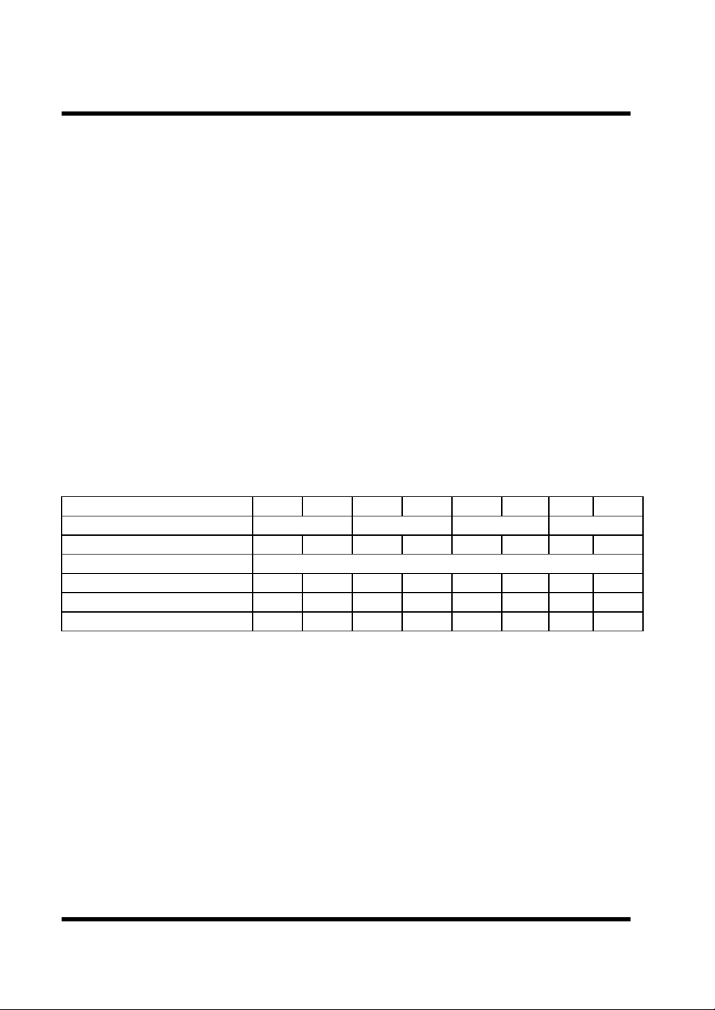
- RESOLUTION AND NUMBER OF DISPLAYED DIGIT
Time Base Selector INT EXT INT EXT INT EXT INT EXT
Gate Time 0.01S 0.1S 1S 10S
Number Of Displayed Digit 5 6 6 7 7 8 8 9
Frequency (Input B) RESOLUTION
80 MHz-99 MHz
100 MHz-999 MHz
1 GHz-3.3 GHz
1 KHz 100 Hz 100 Hz 10 Hz 10 Hz 1 Hz 1 Hz 0.1 Hz
10 KHz 1 KHz 1 KHz 100 Hz 100 Hz 10 Hz 10 Hz 1 Hz
100 KHz 10 KHz 10 KHz 1 KHz 1 KHz 100 Hz 100 Hz 10 Hz
(Table 2)
TIME BASE CHARACTERISTICS
- TYPE : TCO (Temperature controlled oscillator)
- FREQUENCY : 10.000000 MHz
- STABILITY : ±1 PPM(±1 count)
- LINE VOLTAGE STABILITY : Less than ± 1 PPM with ± 10% line voltage
variation.
-TEMPERATURE STABILITY : ±5 PPM from 0° C to 50° C
- MAX. AGING RATE : ±5 PPM/year
- INT. STD. OUT : 10 MHz(internal standard frequency output)
- LEVEL : 1 Vpp or more
- IMPEDANCE : Approx. 600Ω
- EXT. STD. IN : 10 MHz(external standard frequency input)
- LEVEL : 1.5 Vrms to 5Vrms
- IMPEDANCE : Approx. 600Ω
Test Equipment Depot - 800.517.8431 - 99 Washington Street Melrose, MA 02176
FAX 781.665.0780 - TestEquipmentDepot.com
8
 Loading...