

Titan Series Commercial Ramp System
Manufactured in the USA
Installation Manual

IMPORTANT!
Read and follow all labels and assembly
instructions – including warnings and cautions – prior to ramp use!
INSPECTION (BEFORE USE):
1.
Read and follow all labels and as sembly instructions prior t o us e. To obtain a copy of complete
instructions, warnings, and cautions visit www. ezaccess.com or call 1-800-258-8503.
2.
Ensure all fasteners and l ocking mechanisms are in place and tightened. Regularly check and
tighten as needed.
3.
Inspect for damaged or missin g par ts before use. If damaged or missing parts are noted, DO
NOT USE!
4.
Check that all parts are in good condition.
5.
If any part of the system is damaged or loose, DO NOT USE u nt il repairs can be made by a
certified installer or other qualified person.
PROPER SET UP AND USE:
1.
Consult local building codes in regard to securing system for wind loads.
2.
Use ramp only with a qualified h el per .
3.
Always use your lap belt.
4.
Before use, refer to your equipment’s Owner Guide for the proper degree of incline/decline and
chair direction. Never exceed its recommendations.
5.
Do not use if walking surface is unsafe.
6.
Ramp may be slippery when w et or icy.
7.
Proper maintenance and upkeep to the system is vital. DO NOT USE if ramp guards,
handrails, or supports are damaged or unstable.
8.
Confirm that the system is correctly leveled and posi t ioned securely. Periodica l ly check for
ground shifts.
9.
DANGER
system.
10.
If any part of the system is damaged or loose, DO NOT USE u nt il repairs can be made by a
certified installer or other qualified person.
11.
Never place anything under or attach anything to syst em to gain height or to adjust for unev en
surfaces.
12.
Do not use any component not s uppl ied or approved by manufacturer with system.
13.
Do not sit, stand, or climb on guar ds or handrails.
14.
Do not play on or around system, including, but not limited to, r unning, jumping, bicycles,
scooters, skateboards, et c.
15.
Do not use handrails or ramp to support planters, decorations, etc.
16.
Properly support and restr ain system in transit or stor age.
! Metal conducts electricity . Do not use near exposed wiring or hang lights from
MAINTENANCE:
1.
Proper maintenance and upkeep to the system is vital. DO NOT USE if ramp guards,
handrails, or supports are damaged or unstable.
2.
Do not use if surface is cov er ed w ith ice and/or snow. Accumulation must be shoveled and the
tread surface swept clean before use.
3.
At all times, keep system clear of dirt, leaves, and other debr i s t hat may accumulate on the
surface.
4.
Confirm that the system is correctly leveled and posi t ioned securely. Periodica l ly check for
ground shifts.
5.
Ensure all fasteners and l ocking mechanisms are in place and tightened. Regularly check and
tighten as needed.
6.
Ramp may be cleaned with m ild det er gent and warm water (con sult manufacturer before usi ng
abrasives or chemical cleaners). Rinse well and use extra caution when ramp sur fa ce is wet.
7.
For additional care, use, or safety information, please cal l 1-800-258-8503.
– 2 –
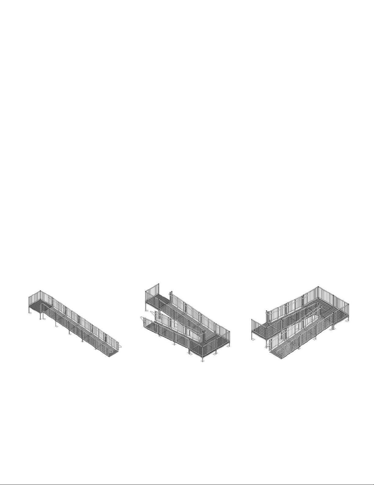
TABLE OF CONTENTS
COMMON RAMP CONFIGURATIONS
System #1
System #2
System #3
BEFORE YOU BEGIN........................................................................ 2
TOOLS NEEDED ............................................................................... 2
ASSEMBLE/SET PLATFORMS ......................................................... 2
ASSEMBLE/SET RAMPS .................................................................. 7
INSTALLING TRANSITION PLATE( S) ............................................... 8
INSTALLING SUPPORT LEGS TO RAMP SECTION(S) ................... 9
INSTALLING PLATFORM GUARDS................................................ 11
INSTALLING RAMP GUARDS ......................................................... 14
INSTALLING HANDRAILS ............................................................... 15
INSTALLING HANDRAIL ATTACHMENTS ..................................... 15
FINAL ST EPS .................................................................................. 20
NOTES ............................................................................................. 21
– 3 –
BEFORE YOU BEGIN:
1. Read and follow all instructions/warnings prior to assembly and use.
2.
Load rating: 100 lbs. psf live load, 300 lbs. concentrated
TOOLS NEEDED:
Tape measure
Level
9/16” socket or wrench
1/2” socket or wrench
3/16” hex key wrench
5/32” hex key wrench
5/16” masonry drill bit (if i nst alling ramp to concrete porc h, st eps, etc.)
Hammer
#3 square drive bit
File
Power drill
Metal cutting chop saw or reciprocating saw
Digging tools (if an obstac le needs to be removed)
Two able-bodied persons needed for installation
Pop rivet gun (needed for chi ld rail and corner cover plate inst allation only)
1. ASSEMBLE/SET PLATFORMS :
1.1 Determine platform height requirement.
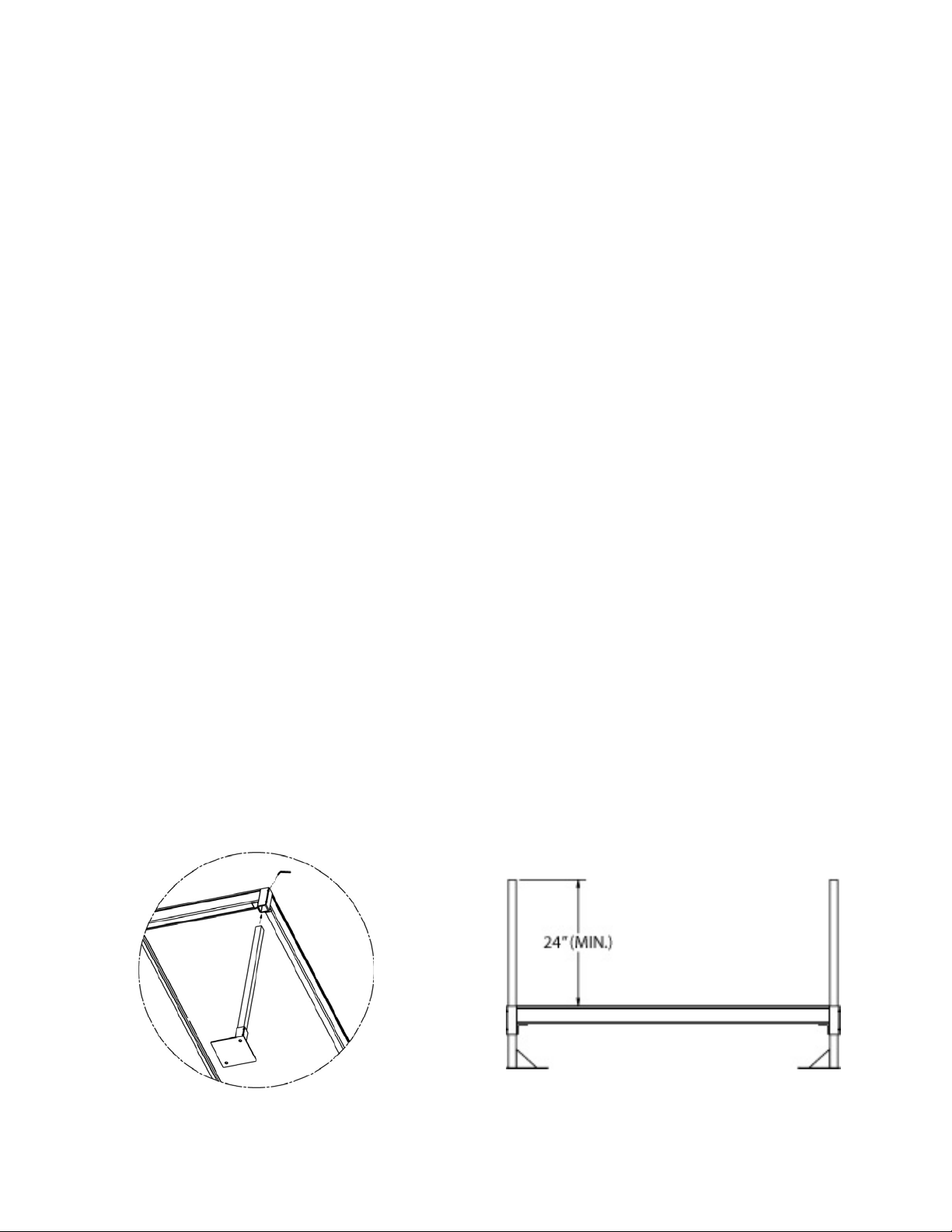
1.1.1 Insert support legs int o corner pockets at corners of platform (FIG. 1). Position foot pads so
that they do not protrude past perimeter of the platform.
used to support the guardr ails and w hen installed, the support t ubes must protrude at least
24” above the platform walking sur fac e ( FI G. 2).
1.1.2 Ensure that the correct le ngt h support tubes are used.
1.1.3 Adjust legs to approximate height required then secure leg adjust ment by tightening
setscrews with 3/16” hex k ey wrench.
1.2 Position platform in desired location then make fina l height and level adjustme nt s.
1.3 Ensure support legs are s ecur e by tightening setscrew s (a total of eight, two in each corner) .
1.4 Assemble all platforms required in this fashion. Guardrails and handrails wi ll be inst alled after
platforms and ramps are assembled and set.
The support legs are a lso
Note:
FIG. 1 FIG. 2
– 4 –

1.5 Platforms over 3 ft . hi gh from the ground require cross bracing.
FIG. 3
FIG. 4
1.5.1 Insert legs into platform and set platform at require d height as described in previous steps.
1.5.2 Separate ends of brace b ands until they go around the 1-1/2” square tube and insta ll four
bands on each leg with the par t containing bolt holes at 90 degrees from each other and in
line with the outer edge of t he foot ( FI G . 3) .
1.5.3 The cross brace will com e assembled with one bolt in the center. The brace assemb ly
should be placed approximately in the middle of the platform legs on all four sides w ith t he
top brace bands approxim at ely 2 ft. from the bottom brace bands.
1.5.4 If needed for the location, t r im the e nds of the brace assembly to fit.
1.5.5 Drill one 11/32” dia. hole on center approximately 1/2” from the end of each brace.
1.5.6 Install brace assembly using four 5/16”-18 x 1-1/2” l ong car riage bolts, nuts and washers in
the desired location (FIG. 4) .
1.5.7 Tighten all fasteners se curely.
1.6 If using two platforms to create a turn-back, connect platforms using the two Dual Platform
Connector Kits provided.
1.6.1 On the first platform, install a dual platform connector on each of the two legs t hat w il l be
adjacent to the second plat form. Make sure that the pocket o f the co nnect or is oriente d to
the outside of the first platform in the direction of the secon d platform and that the setscrew s
are facing in a direction wher e t hey will be accessible (FIG. 5) .
1.6.2 Install legs and set the first platform at required heig ht (as described in previous steps).
1.6.3 Bring both connectors up until they touch the bottoms o f the corner pockets in the plat forms
and tighten the setscrews securely (FIG. 6).
1.6.4 On the second platform install the two legs that will be opposite the first platfo r m an d set
them to the same height as t he first platform, then set the t w o c orner pockets of the second
platform on top of the platform c onnectors (FIG. 6).
1.6.5 Install two 1-1/2” square x 36” long tube through pl atform corner pockets and connectors
until it aligns with bottom of connector, then tighten all setscrews securely ( FIG . 7 ).
– 5 –
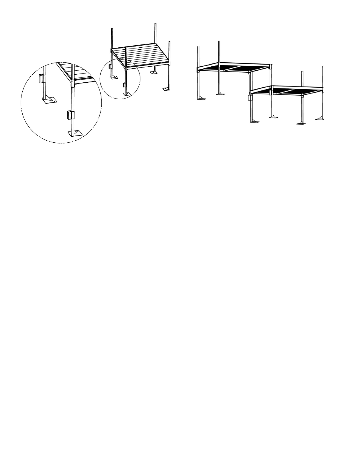
FIG. 5
FIG. 6
1.7 Platforms can also be combined in any direc t i on in multiples of 64-7/16” to create a deck. The initial
steps are similar to Sec. 1.5, using two platforms to create a t urn-back. Refer to the project
drawings for the specific deck configuration.
1.7.1 On the first platform, install a dual platform connector on each of the two legs that w il l be
adjacent to the second plat form. Make sure that the pocket o f the connector is oriented to
the outside of the first platform in the direction of the secon d platform and that the setscrew s
are facing in a direction wher e t hey will be accessible (FIG. 5).
platforms will be used to creat e a deck but this may not always be t he case. Since the first
platform is the one that set s t he height for the rest, it is strongly r ecom m ended that the first
platform be located at a door or ot her f ixed point where height is critica l regardless of its
position in the deck.
1.7.1.1 If more than one platform is connected to the “first” platform, install a dual platform
connector on the remainin g legs as needed. Planning will be required to make sure
not only that the connecto r s ar e or iented in the right direction, but also that the
subsequent platforms are supported by at least two legs as the deck is assembled
before installing the legs i n the platform (Refer to Sect ion 1.7.8 for other
requirements).
1.7.2 Install the legs and set the first pl at form at the required height as described in the previous
steps.
1.7.3 Bring all connectors up un til they touch the bottoms of the corner pockets in the platform and
tighten the setscrews securely (FIG. 6).
1.7.4 On the second platform (a nd al l subsequent platforms), inst all the two legs that will be
opposite the first (previous) platform and set to the same height as t he f irst platform, then set
the two corner pockets of the sec ond platform on top of the p latf orm connectors in the first
platform (FIG. 6).
1.7.4.1 Same as the first platform, if more than one platform is connected to t he “ second”
platform, install a dual platform connector on additional legs as needed, bring the
connectors up until they t ouch the bot t oms of the corner pockets and ti ghten all
setscrews securely. Planning will be required to make sure not only that the
connectors are oriented in the right direction but also that the subsequent platfor ms
are supported by at least two legs as the deck is assembled before installing the legs
in the platform (Refer to Sect ion 1.7.8 for other requirements) .
1.7.5 If the platform connector is in a location that will require a gu ar d, filler section or corner post
(typically the outer edge o f the deck), install the 1-1/2” squar e x 36” long tube provided
through the platform corner pocket and connector u nt il it a li gns w it h t he bottom of the
connector and tighten all set scr ews securely (FIG. 5).
and other components is described elsewhere in the ma nual.
: Installation of platfor m g uar ds
Note
Usually the upperm os t
Note:
– 6 –
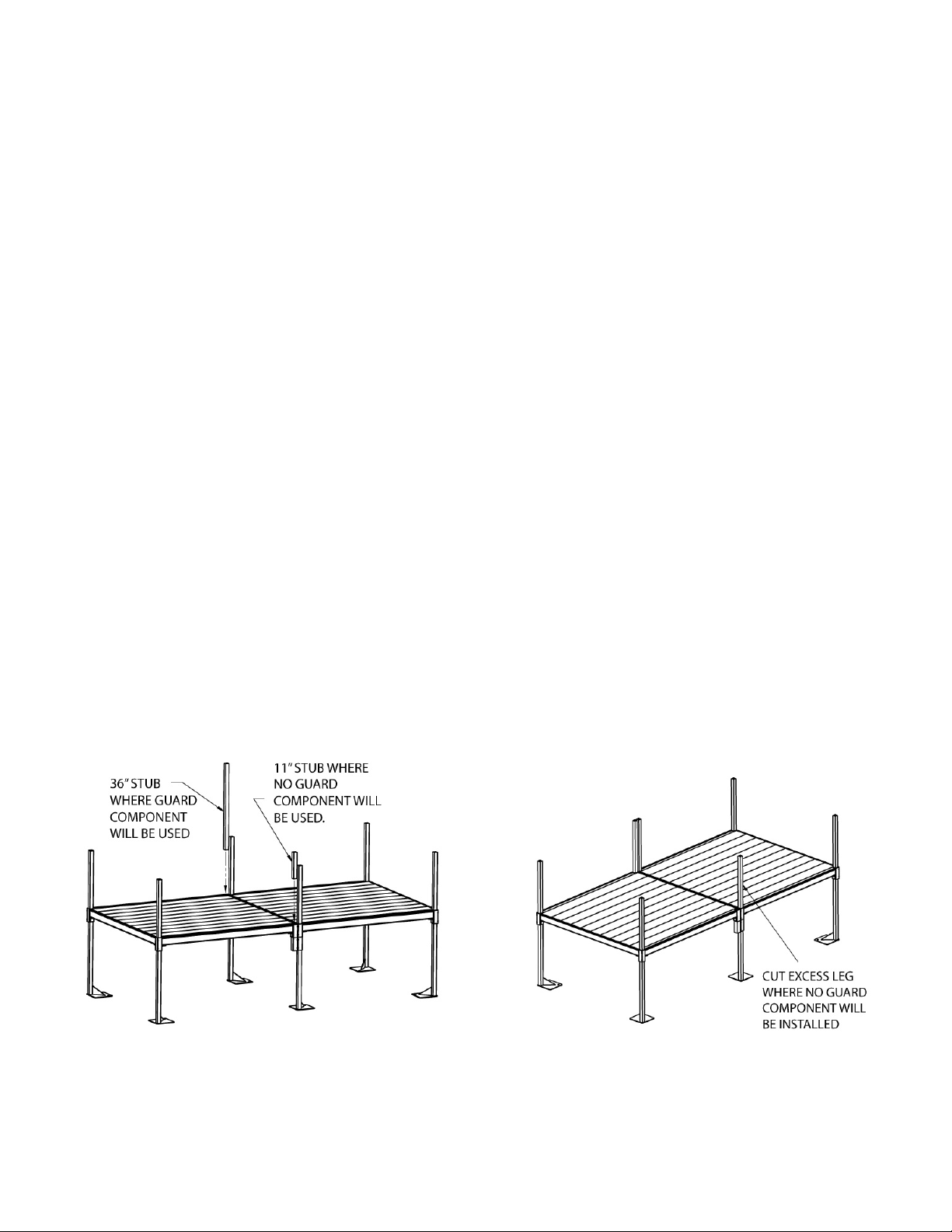
1.7.6 In all locations where there will be no guards or filler sect ion s install the 1-1/2” square x 11”
FIG. 7
FIG. 8
long tube provided through the platform corner pocket and connector until it ali gns with the
bottom of the connector a nd t ight en all setscrews securely (FIG. 5).
1.7.7 At this point there will be o ne or m or e legs that extend above the plat form deck and will
be used to attach a guard, filler s ect ion or corner post. Mar k these l egs at t he top of the
corner pocket and cut the leg off at or slightly below the mark (FIG. 8).
appearance and quality of the cut is not critical since these areas will be covered with a plate
in later steps. What is critical i s t hat the leg not stick up past the deck far enough to interfere
with the plate when it is installed.
1.7.8 Additional platforms are added by repeating steps 1.7.4 thru 1.7.7 until the de c k is complete.
There are, however, a few requirements that should be follow ed r egardless of platform’s
position within the deck.
1.7.8.1 There should always be one leg and one “stub” in a dual platform connector. Thi s
may require repositioning a connector from the way it w as initially oriented (or
replacing a stub with a leg) depending on the configuration.
without a leg in a d ual platform co nnector.
1.7.8.2 Where four platforms come together, the two legs should be oriented so that they are
diagonally opposite fro m e ac h ot her ( FIG. 9).
1.7.8.3 Whenever poss ible, especially where four plat forms come together, the dual platform
connector on one side of a plat form should be oriented in the opposite direction from
the other side and the orientat ion should then be alternated as the deck is created
(FIG. 10).
1.7.8.4 Regardless of connector orientation, m ake sure there is a mini m um of two legs
installed in each platform ’s corner pockets (FIG. 11).
1.7.9 Once the deck is complete all areas where platform s c onnect that are not used t o at tach a
guard, filler section or corner post must be covered w ith a Corner Cover Plate (FIG. 12).
1.7.9.1 Use the corner cover plate provided to mark the location of the hole in the deck and
drill four holes between 0.129” and 0.133” dia. ( #30 drill size).
1.7.9.2 Use the four 1/8” dia. rivets provided to attach the corner cover plate.
1.7.9.3 Use two cover plates where four platforms come toget her .
Never use two “stubs”
Note
: The
not
– 7 –
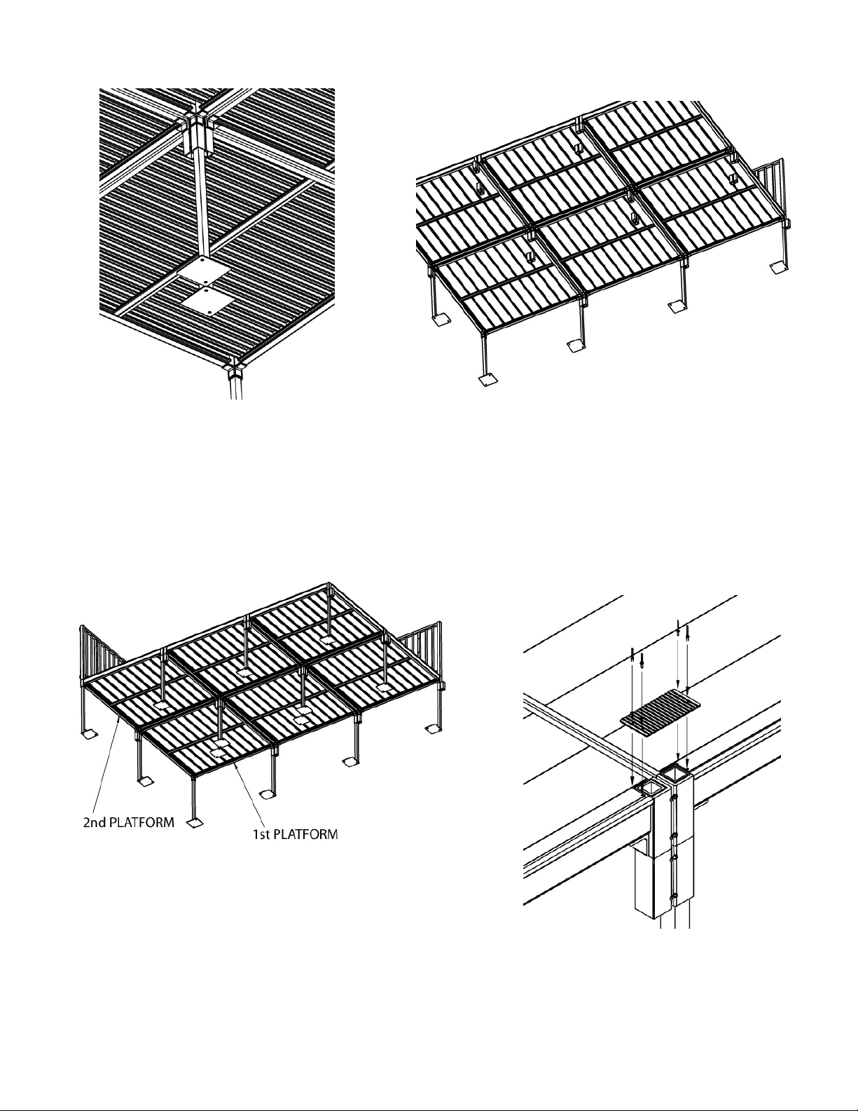
FIG. 9
FIG. 10
FIG. 11
FIG. 12
– 8 –

2. ASSEMBLE/SET RAMPS:
FIG. 13a
FIG. 13b
FIG. 13c
2.1 Begin setting ramps with t he uppermost ramps in the system.
2.2 There are three different br acket types that are used to assemble ramp sections (see FIG. 13a,
FIG. 13b and FIG. 13c). All three bracket t ypes are fit into the side rail of the ramp section and
are best installed with the ram p sect ion placed upside down us ing t he 5/ 16-18” x 1.5” hex bolts
and washers.
the ramp section side rail as well as aligns with the threaded inserts preinstalled in the ramp
section side rails. Use ½” wrench or soc ket t o sec ure fasteners.
2.2.1 End support assembly bracket (FIG. 13a): These brackets come in a left and r ight pair
and attach to the upper and lower end of a ramp run to support t he ends of the ramp run
when combined with supp or t legs. These brackets also provid e at t achment points for the
guardrails.
2.2.2 Guard brackets (FIG. 13b): This pair of brackets provides an attachment point for the
guardrails at the mid-point of a ramp section.
2.2.3 Center support asse mb ly bracket (FIG. 13c): This pair of brackets joins ramp sections
together and is required wher e r amp sections meet in a ramp run. They support the ramp
at this point when combin ed w it h support legs and provide attachment points for the
guardrails.
: Take care that the narrow edge of the bracket engages the t r ough f ormed in
Note
2.3 If using a single ramp as the firs t upper section:
2.3.1 Lay the ramp section upsi de dow n.
2.3.2 Install end support assembly brackets (FIG. 13a) at bot h ends of the ramp section. Thi s
will require two pairs of end suppor t br ackets.
diameter studs protrudin g from the brackets are positione d toward the outer end of the
ramp section.
2.3.3 Install one pair of guard brackets (FIG. 13b) at mid-point of ramp section in similar
manner.
2.4 If using two or more ramp sect ions for uppermost ramp run:
2.4.1 Lay ramp section end-to-end upside down on a lev el surface (a level surface will make
sections easier to connect).
2.4.2 Install one pair of center support brackets (FIG. 13c) at each junction of two ramp
sections.
respect to threaded inserts in the ramp sections to a void problems aligning the guar ds
and handrails later. This may require measuring. There is a centering mark on the
support bracket to assist w ith this process.
2.4.3 Install end support ass embly brackets (FIG. 13a) at bot h ends of the ramp run (t h is will
require two pairs of end support br ackets).
studs protruding from the br ackets are positioned tow ar d t he outer end of the ramp
section.
2.4.4 Install one pair of guard brackets (FIG. 13b) at the mid-point of each ramp section
making up the run.
2.5 If using as a turn or turn-back:
It is critical that the center support bracket be positioned equally w ith
Note:
– 9 –
: Make sure that the two larger
Note
: Make sure that the two larger diameter
Note

2.5.1 Ramp must be positione d t o one side or the other of the platform an d s hould always be
positioned to the outside of the t ur n.
2.5.2 Position the ramp to one side o f t he platform so that the edge of the tr ansition plate is
4½” from the outer edge of the pl at form (FIG. 14).
secured later.
2.6 If the system requires an inter m ediate “resting” platform, t he ramps must be positioned in the
center of the platform (see FIG. 28 and FIG. 34).
2.7 Repeat this procedure when assembling and setting ramp runs until the lowest r un is r eached.
2.8 The lowermost ramp section ( t he only section that contacts t he gr ound directly) is calle d t he
starter ramp section. This section can be identified by the taper at one end of the ramp.
2.8.1 The underside of the taper will sit directly on the ground so an end support assembly is
not required.
2.8.2 Install (1) pair guard brac kets (FIG 13b) at mid point of ramp section and either an end
support assembly, if the starter section is the only r amp in the r un, or a center support
assembly if connecting to anot her r amp section as described in pr evious steps.
3. INSTALLING TRANSITION PLATE(S)
3.1 A transition p lat e i s r equired at any point that a ramp section or ramp run me ets a platform.
3.2 Install a transit i on plate into each end of the ra mp se ct ion( s) by turning the section(s) over, then
inserting as shown in FIG. 15.
3.3 Position ramp section so that the transiti on plate fully overlaps t he platform surface as shown in
FIG. 16. Make sure that the top tr ansit i on plate overlaps the support i ng surface as far as
possible.
(transition plates will be secured later, as shown in FIG. 42).
The transition plates may not r est fl at on platform at this point and thi s is normal
Note:
: The transition plate will be
Note
FIG. 14 FIG. 15 FIG. 16
– 10 –

4. INSTALLING SUPPORT LEGS TO RAMP SECTION(S):
FIG. 19
4.1 Install leg support brackets and suppor t legs to ram p sect ion(s) as shown in FIG . 17.
Ramp support legs should ext end at least 1” past the support t ube br acket but no more than 20”
above the walking surface of the r amp (FIG. 18).
FIG. 17 FIG. 18
Note:
4.2 Beginning at the upper end of the ramp system, insert a support leg into the leg suppor t bracket
(FIG. 19) and position the foot pad on the leg so it ext ends beneath the ramp.
4.3 Position the leg support bracket onto the end su pport assembly over the 3/8” diameter studs.
4.4 Check the height of the support tube abov e t he w alking surface of the ramp.
4.5 Install the leg support bracket to the end su ppor t assembly with two 3/8”-16 nuts and 3/8”
washers.
4.6 Level the leg support bracket and secure in level pos ition using a 9/16” wrench.
4.7 Insert 3/8-16 x 3/4” bolts (two each) into the threaded holes in the leg support bracket.
4.8 Adjust the ramp height until the transition pl at e is r esting flat on the platform su r face. Tighten
both bolts, and then repeat process on the opposite s ide o f the r amp.
4.9 Repeat proc ess on the lower end of the ramp, again insuring that the tr ansition plate rests flat on
the platform surface.
4.10 Use same procedure to ins t all the support legs on the center sup por t br ackets (if present).
4.11 Have a helper site down the t op edge of the ramp side rail and a dj us t r amp height until top edge
of ramp side rail is straight, then tighten adjusting bolt to maintain this level.
important that the support legs are adjusted correctly so the ramp sections ar e aligned in a
straight fashion, neither bow ing down or up (see FIG. 19 for c orr ec t positioning). Failure to adju st
properly will result in di ffic ult y attaching the ramp guards and handrails later.
4.12 Repeat this procedure when assembling and placin g r am p section(s) between platforms until the
lowest section is reached.
Note
: It is
– 11 –

4.13 The lowest ramp run will always begin with a st ar t er section. This section requires t he s ame
installation procedure wit h two exceptions.
4.13.1 There is no end support assembly on the tapered end of the ramp section and, since it rests
on the ground, no support leg is required.
4.13.2 Only one transition plate is required at the top of the ramp run.
4.14 Install plugs in the top of all support legs.
4.15 Ramps over 3 ft. high from the ground require cross bracing.
4.15.1 Insert legs into the ramp and set ramp at t he r equired height as described i n previous steps.
4.15.2 Separate the ends of brace bands unt il they go around the 1-1/2” square tube and install two
bands on each leg. Orient t he band so t hat the legs with the holes ext end under the ramp
(FIG. 20).
4.15.3 The cross brace will come assembled with one bolt in the center . The brace assembly
should be placed approxi mately in the middle of the r amp legs with the top brace bands
approximately 42 inches from the bottom brace bands and the brace assembly under the
ramp.
4.15.3.1 If needed for t he location, trim the ends of the brace assembly to fit.
4.15.4 Drill one 11/32” dia. hole on center appr oximately 1/2” from the end of e ach brace.
4.15.5 Install brace assembly using four 5/16”-18 x 1-1/2” long carriage bolts, nuts and washers in
the desired location (FIG. 20).
4.15.6 Tighten all fasteners securely.
FIG. 20
– 12 –

5. INSTALLING PLATFORM GU ARDS:
FIG. 21a
5.1 Depending on the syste m con fig ur at i on, following are four platform guardrail component options
that may be used that ma y be used in different combinations:
Five-foot and six-foot guard sections (FIG. 21a)
Guard post (FIG. 21b)
Guard filler sections for fiv e -foot and si x -foot platforms (FIG. 21c)
Guard corner sections for five-foot and six-foot platforms (FIG. 21d)
FIG. 21b FIG. 21c FIG. 21d
– 13 –

5.2 There are three basic plat f or m arr angements: turn, turn-back, and straight t hr ough. Select
appropriate guardrail installation and assemble rails as shown in FIG. 22 through FIG. 28.
FIG. 22 FIG. 23 FIG. 24
5.3 If pla tform turns into a door at the top of the system:
5.3.1 Place one guard post over t he suppor t leg extending out of the platform corner pocket,
opposite both the door and ram p side (FIG. 22). Do not tighten.
should be oriented toward the inside.
5.3.2 Place two 5 ft. guards over support legs protruding out of plat form corner pockets
adjacent to guard post (FIG. 23) and engage tabs on guard section into tab brackets
on guard post. Do not tighten setscrews.
5.3.3 Place guard filler sectio n over the remaining support leg w ith t he tab brackets facing
the outside of the platform (FIG. 24).
5.3.4 Tighten lower two 3/8”-16 setscrews in each of the f our vertical guardrail posts with
3/16” hex key wrench securely (FIG. 25).
5.4 If platforms are used to create a turnback:
5.4.1 Both platforms will use the same guard components as above except in mirror image (shown
in FIG. 26).
5.4.2 Tighten lower two 3/8”-16 setscrews in each of the four vertical gu ar dr ail posts with 3/16” hex
key wrench securely (FIG. 25).
5.5 If platform is used as a turn from one ramp to another (FIG. 27):
5.5.1 Place one guard post over s uppor t le g ex t ending out of the platform cor ner pocket opposite
both ramps (tab brackets should be oriented toward t he insi de) . Do not tighten.
5.5.2 Place two 5 ft. guards over support legs pr ot r uding out of platform corner pockets adjacent to
guard post.
5.5.3 Engage tabs on 5 ft. guar d sect ions into tab brackets on the guard post, but do not tighten.
5.5.4 Place guard corner secti on over the remaining supp or t leg.
5.5.5 Tighten lower two 3/8”-16 sets cr ew s in each of the four ver t ical gu ar dr ail posts with 3/16” hex
key wrench securely (FIG. 25).
5.6 If pla tform is used as a straight through resting platform (FIG. 28):
5.6.1 Place two guard posts over prot r udi ng s upport legs on one end of the pl atform that a ramp is
joining.
capped.
5.6.2 Place two 5 ft. platform guards two over support legs, ma k in g sur e to engage tabs on
platform guards into tab brackets on guard posts.
5.6.3 Tighten the lower 3/8”-16 setscrews, two in each of the four ver tical guardrail posts with 3/ 16”
hex key wrench securely (FIG 25).
The unused tab brackets should be oriented to the outs i de of the platform and
Note:
: Tab brackets
Note
– 14 –

5.7 If platforms are being us ed to create a deck the entir e out er edge of the deck must be guarded.
5.7.1 Installation of the guard s at a cor ner is t he same as turning into a door at the t op of the
system. Refer to FIG. 22 and FIG. 23.
5.7.2 Installation of the guard s i n a s traight run is similar except t hat only one guard section & post
are needed so the unused t ab br ackets on the post should be orient ed t o t he outside of the
deck & capped (same as FIG. 28).
5.8 Install plugs in the top of all open guard posts.
FIG. 25 FIG. 26
FIG. 27 FIG. 28
– 15 –

6. INSTALLING RAMP GUARDS:
6.1 Ramp guards come in left and r ig ht pair s and are not interchangeable from side-to-side. For all ra mp
sections other than the starter section:
6.1.1 Install the Ramp Guard P os t Spacers over the 5/16”-18 studs protruding from t he
brackets previously instal led on the ramp section wit h t he long end of the spacer pointing
up (FIG 29).
6.1.2 Attach the ramp guard to the r amp section by positioning t he lower holes in the ramp
guard posts over the stud s.
6.1.3 Once the guard is in place , place a 5/ 16”-18 nuts and 5/16” f lat w as her s on each stud.
Take up play with the nuts but do not t ighten ( this will help with alignment during handrail
installation).
6.2 For the starter section, tw o of the t hr ee guard vertical posts ar e installed in the same manner.
Secure the lowermost pos t using a 5/16”-18” x 2 3/4” carriage b olt inserted thru the holes in the
ramp side rail and secure d with a 5/16”-18 nut and 5/16” fl at w as her (FI G 30) .
FIG. 29
FIG. 30
– 16 –

7. INSTALLING HANDRAILS:
FIG. 33a
FIG. 33b
FIG. 33c
FIG. 33d
FIG. 33e
FIG. 33f
7.1 Ramp handrails are supplied in left and right pairs and are not interchangeable.
7.1.1 Starting at the lower end of ramp system, attach first handrail section by aligning holes i n
the handrail brackets with t he hol es in the guard vertical posts (FI G . 31). Secure with one
5/16”-18 x 2 1/2” button head bolt , washers and nylock nut (place two washers and nylock
nut on outside of ramp).
7.1.2 Repeat on all three handrail brackets per handrai l section. Secure bolts, but do not tighten.
7.1.3 Install handrails on oppo site side in the same manner.
7.1.4 Install 4” joiner assemb ly to up hi ll e nd of the previously installed handrail section (FIG.
32), passing the next handrai l sect ion over the joiner assembly, then secure to guardrail in
same manner as previous handr ail.
7.1.5 Continue until all ramp handrail sections are inst al led.
7.1.6 Once all handrails are con nect ed tighten all fastener s connecting handrails to guards, as
well as guards to ramps a nd jo iners, securely.
FIG. 31 FIG. 32
8. INSTALLING HANDRAIL ATTACHME NTS :
8.1 There are five different handrail attachments that may be used in different c ombinations to
finish the handrail installation:
Lower loop (FIG. 33a)
Upper loop (FIG. 33b)
5-degree elbow (FIG. 33c)
90-degree elbow (FIG. 33d)
When using with a joiner, DO NOT trim more than 3/8” off the short le g of t he
90 degree elbow as this w ill not allow the joiner to seat proper ly
Adjustable elbow (FIG. 33e)
Dual termination loop (FI G . 33f)
: 90 degree elbow will require trimming to size.
Note
– 17 –

8.2 At the bottom of the ramp (i.e. , gr ound), install two lower loops into the ends of each handrail
FIG. 34
(FIG. 34).
8.2.1 Install upper portion of loop to handrail using a 4” joiner . Tig ht en s et screw enough to hold
in place, but leave loose enoug h to rotate.
8.2.2 Rotate lower portion of lo op until it lines up with ram p guar d post. Mark center, t hen dr ill
5/16” hole through post. Secure lower end of loop with 5/16”-18 x 2” button head bolt
through the drilled hole and into threaded insert in lower end of loop.
8.2.3 Attach tab on bottom of loop by drilling a 5/16” dia. hole through the channel at the end of
the ramp guardrail and se cur in g with a 5/16”-18 x 3” button head b olt, t hr ee washers and
nut. Place nut and two washers on outside of ramp and place one washer between the
head of the bolt and the tab on the lo op.
8.2.4 Tighten all fasteners se curely.
8.3 At a straight through res t i ng platform (FIG. 34):
8.3.1 Install two upper loops at the top of the ramp and two lower loops at the start of the nex t
run in the same manner as above.
: The only difference b et ween the upper and lower
Note
loop installation is that the upper loop uses a 4” ring joiner inst ead of the standard 4” joiner.
– 18 –
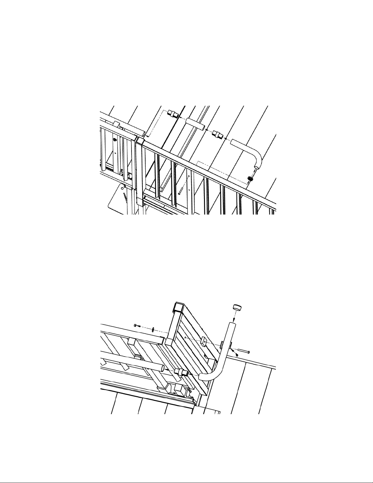
8.4 At a turn platform on the outside, non-turn side (both wher e a t he t op of a ramp meets a platform
and where a ramp starts at a plat form) as shown in FIG. 35:
8.4.1 Use a ring joiner to attach one 5 degree elbow to ramp h andrail.
8.4.2 Hold 90 degree elbow in position and mark for trimm ing.
8.4.3 After trimming, test fit elbow.
8.4.4 When fit is confirmed, in st all thr eaded insert into short end of e lbow with a hammer.
8.4.5 Connect long side to 5 de gr ee el bow with a ring joiner.
8.4.6 Connect short end to ver t ical tube on guard with 5/16”-18 x 2” button head screw.
8.4.7 Tighten all fasteners se curely.
FIG. 35
8.5 At a turn platform at top of system on inside turn side (FIG . 36):
8.5.1 Hold 90 degree elbow and handr ail bracket in position and mark for trimming.
8.5.2 After trimming, test fit elb ow along with handrail brac k et and spacer.
8.5.3 When fit is confirmed, in st all e nd cap on open end of long leg o f elbow.
8.5.4 Attach short leg of elbow t o handrail tubes with a ring joiner.
8.5.5 Attach handrail brac ket and spacer to guard filler sect ion by dr il l ing 5/ 16” dia. hole through
guard filler picket, and the n secur e using one 5/16”-18 x 3” bolt, nut and washer.
8.5.6 Attach elbow to handrail bracket using one 1/4” x 1” lon g s el f drilling square drive screw .
8.5.7
Tighten all fasteners securely.
FIG. 36
– 19 –
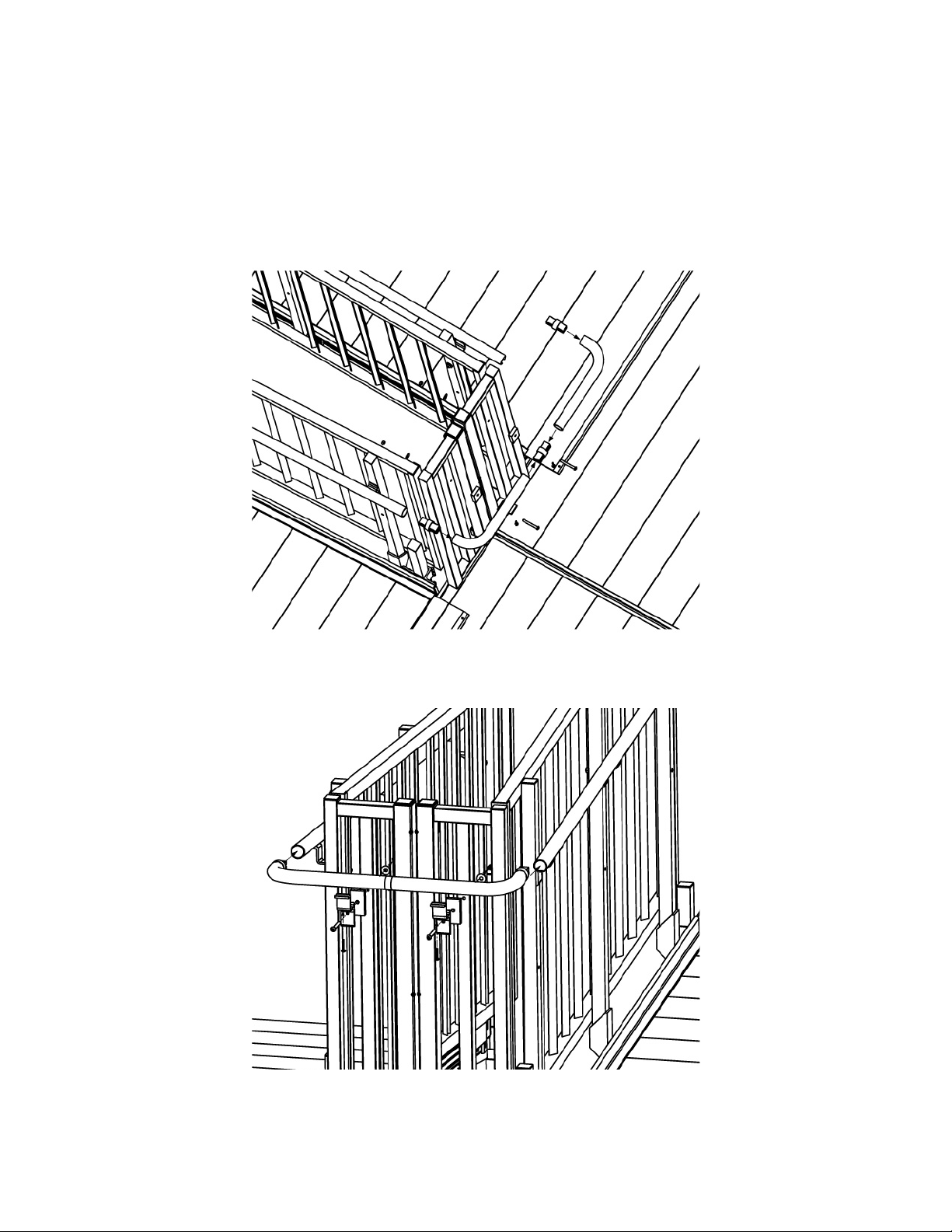
8.6 At a turn-back platform on the insi de, t ur n-back side (FIG. 37):
8.6.1 Hold two 90 degree elbows in position and mark for trimming.
8.6.2 After trimming, test fit elbows, handrail brackets and spacers.
8.6.3 Attach long legs of elbows in the m iddle with a ring joiner, and then attach both elb ow s to
handrail tubes with ring joiner s (FIG. 38)
8.6.4 Attach handrail brac kets and spacers to guard filler section by drilling 5/16” dia. hole
through the filler picket.
8.6.5 Use one 5/16”-18 x 3” bolt, nut and washer per bracket to secure.
8.6.6 Attach elbows to handra il br ackets using 1/4” x 1” self drilling s quar e drive screw per
bracket.
8.6.7 Tighten all fasteners se curely.
FIG. 37
FIG. 38
– 20 –

8.7 At an intermediate turn platform on an inside corner (FIG. 39):
8.7.1 Hold two 90 degree elbows in position with the adju stable elbow and mark for t r i m ming.
8.7.2 After trimming, test fit elbows, handrail brackets and spacers.
8.7.3 Attach long legs of 90 degree elbows to adjustable e lbow w ith r ing joiners then attach bot h
elbows to handrail tubes w it h ring j oi ner s .
8.7.4 Attach handrail brac kets and spacers to guard post using one 5/16” x 1-1/2” self drilling
square drive screw per bracket to secure (FIG. 40).
8.7.5 Attach elbows to handra il br ackets using one 1/4” x 1” long self drilling square dr ive screw
per bracket, then Tighten all fastener s secure ly.
FIG. 39
FIG. 40
– 21 –
8.8 When child rails are required, the lower ( child) handrails and the vario us r et ur ns and connectors
FIG. 41
are installed in the same manner as the upper (normal) rail us ing the lower set of holes provided.
Refer to instructions in previous steps.
8.8.1 The upper (adult) handrail is also installed in the same m anner except the upper and lower
termination loops are not used. These components will be replaced by either an upp er or
lower dual termination loop (FIG. 41).
8.8.2 Install connector piece s of dual t ermination loop into ends of upper and lower handrails.
8.8.3 Drill two ho les between 0.129” and 0.133” dia. (#30 drill size) through the han dr ai l t ube and
the connector piece in the underside of the end of each handr ail where a dual termination
loop is used. Drill one hole appr oximately 3/4” from t he end and the second hole
approximately 1-3/4” from the end.
8.8.4 Install two 1/8” dia. rivets (provided) in the end of each handrail using holes dr i lle d in
previous step.
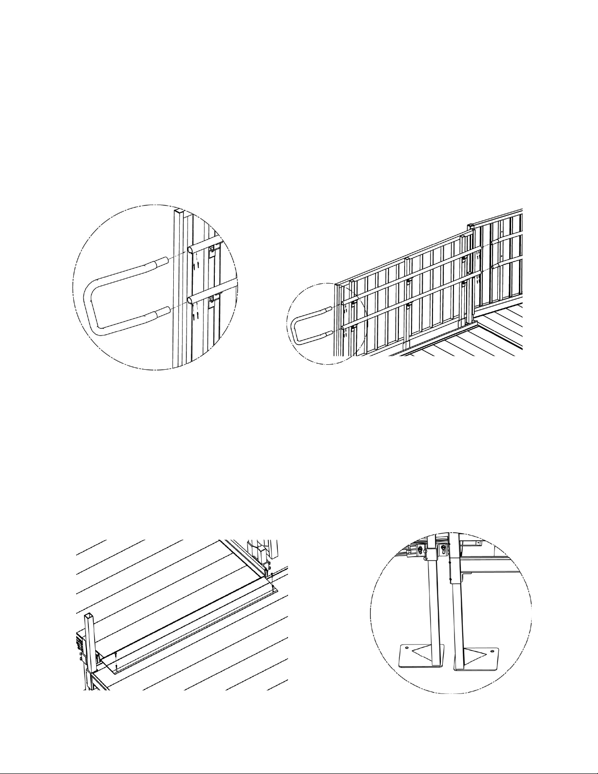
9. FINAL STEPS:
9.1 Once all handrails and components have been positioned and all fast eners tightened, screw
transition plates to platforms using two 1/4” x 1” lon g s el f dri ll ing square drive screws (FIG . 42).
9.2 Ramp and platform legs can be secured to t he gr ound using stakes or con cr ete anchors and the
holes provided in the feet, if needed (FIG. 43).
9.3 Ensure that all fasteners are in place and secure.
9.4 Walk on the ass embled system, chec king for any undue movement.
9.5 Remove any debris and metal chips.
9.6 Ensure that t he level and slope has not shifted during installation.
Check that all handrail ends are terminated with loo ps, r et ur ns , or end c aps.
9.7
: Hardware not included.
Note
FIG. 42 FIG. 43
– 22 –

NOTES:
Thank you for choosing
Please visit
www.ezaccess.com or call 1-800-258-8503
for all your ramp and step needs.
– 23 –

10257 REV 06-19-13
© EZ-ACCESS®, a division of Homecare Products, Inc. All rights reserved.
distributed, rep rod uce d, or re us e d wit h out the express written permissi on of E Z-ACCESS.
for all your ramp and step needs.
Please visit
www.ezaccess.com or call 1-800-258-8503
All text and images contained in this document are proprietary and may not be shared, modified,
 Loading...