

EZ-ACCESS PASSPORT PL120SP3651, PASSPORT PL144SP3651, PASSPORT PL120TP3860, PASSPORT PL168SP3651, PASSPORT PL168TP3860 Installation Supplement Manual
...
Manufactured in the USA
2-YEAR WARRANTY. Please register at www.ezaccess.com/warranty-satisfaction.
© EZ-ACCESS®, a division of Homecare Products, Inc. All rights reserved.
All text and images contained in this document are proprietary and may not be shared, modified,
distributed, reproduced, or reused without the express written permission of EZ-ACCESS.
18798 REV 06-27-19
PASSPORT® Vertical Platform Lift (VPL)
Installation Supplement for
120” (10’), 144” (12’), and 168” (14’)
Models: PL120SP3651, PL120TP3860, PL144SP3651, PL144TP3860, PL168SP3651, & PL168TP3860
Image shown is a 14’ PASSPORT®
Vertical Platform Lift with Straight
Platform and 2 Back Braces.

TABLE OF CONTENTS
Section 1 .......................................... UNCRATING THE VPL
Section 2 .......................................... GUARD RAMP ACTIVATING BAR
Section 3 .......................................... INSTALLING AND CONNECTING BATTERIES
Section 4 .......................................... LIFTING THE VPL
Section 5 .......................................... INSTALLING BACK AND SIDE BRACING
Section 6 .......................................... REMOVE REMAINING SHIPPING MATERIALS
Section 7 .......................................... CONTROL VOLTAGE SAFETY SERVICE SWITCH “HOOD SWITCH”
Section 8 .......................................... INSTALLING THE PLATFORM GATE
Section 9 .......................................... INSPECTION AND TESTING
Section 10 ........................................ INSTALL TOWER PANELS
Section 11 ........................................ FINAL TESTING
INTRODUCTION
This Supplement covers installation for the 120” (10’), 144” (12’), and 168” (14’) heights of the PASSPORT® Vertical Platform
Lift. Throughout this document, the PASSPORT Vertical Platform Lift is also referred to as “VPL” or “Lift”.
IMPORTANT SHIPPING INFORMATION
The PASSPORT Vertical Platform Lift is shipped with a packing list. Confirm all items are present before starting
installation. Open shipping boxes and inspect for damage or missing parts. If damaged or missing parts are noted,
DO NOT INSTALL OR USE.
Check for shipping damage immediately upon receipt and note any freight damage on freight bill while driver is
still present. Contact shipper right away with any freight damage concerns. In most cases, freight damage claims
will not be allowed unless noted on the freight bill. Pictures of damage before the unit is unpacked can be very
helpful.
SYMBOLS, SAFETY, AND WARNINGS
The WARNING symbol indicates a potentially hazardous condition/situation. The safety warnings throughout this
manual, and on your equipment, if any, are for the protection of people and property. Failure to abide by safety
warnings will result in a waiver of all liabilities, loss of your warranty, and could result in equipment damage and or
failure, property damage, risk of serious bodily injury, and or death, to operators, riders, and those nearby the symbol
may appear in various colors and in conjunction with other symbols.
The NOTE symbol indicates important information. Failure to obey all notes could result in improper operation, less-
than-optimum equipment performance, and at the sole discretion of the equipment manufacturer, may void your
warranty. The symbol may appear in various colors and in conjunction with other symbols.
ATTENTION INSTALLER: VERIFY PRIOR TO INSTALLATION
This Supplement covers installation for the 120” (10’), 144” (12’), and 168” (14’) PASSPORT Vertical Platform Lifts,
which differ from the 44”, 52”, and 72” PASSPORT lifts. Use this Supplement in conjunction with the PASSPORT®
Vertical Platform Lift (VPL) Installation Manual, following all warnings and safety directives in all documents. For
replacement copies, please call 1-800-451-1903.
Professional installation is required.
Anchoring and bracing drawing details, if required, are the responsibility of the installer.
The installer must ensure the structure the VPL braces will be mounted to, and the concrete pad the VPL will be
anchored to, are of adequate structural integrity, as determined by the installer and the authority having jurisdiction
(AHJ) local to the VPL installation site.
The VPL platform must be at least 3/8” but no more than 3/4” from the edge of the upper landing (horizontally).
The VPL platform guard walls must be at least 2” but no more than 3” (horizontally) from walls or other obstructions.
The VPL is supplied with a 12’ AC power cord. It is the installer’s responsibility to verify local codes and regulations
regarding power supply and electrical connections. Custom power cord lengths are available.
Confirm the structural integrity of any existing fascia.
Verify that the upper landing area is level.
Page | 2

Read the and understand the Installation Manual and all Supplements and Addendums in their entirety. Understand
and learn the location and function of all the features, weight capacity, safety devices, and labels before operating
any PASSPORT Vertical Platform Lift.
Determine which side the guard ramp will be attached to and verify adequate clearances.
Platform must travel up and down and guard ramp must fold and unfold without interference or obstruction.
Refer to the Top Landing Gate Placement and Installation section if installing a Top Landing Gate.
Layout installation site taking into consideration VPL entry and exit points, height, and electrical supply location.
Check for adequate headroom clearance above VPL platform before installation.
WARNINGS
Weight capacity: 750 pounds.
Read the and understand the entire User Manual and the Installation Manuals, including Supplements and
Addendums, in their entirety. Understand and learn the location and function of all the features, safety devices, and
labels before operating any PASSPORT Vertical Platform Lift.
Tower panels must be handled with extreme caution and care; they can be sharp on the edges and can become
dangerous if falling or sliding. Installer must ensure the safety of all people, animals, and property whenever working
with panels.
The VPL must be anchored “plumb” to a level, 3,500 PSI concrete pad at least 4” thick. Minimum pad dimensions are
41” x 50” to anchor the legs and support the tower. However, a larger pad will be needed if it is desired that the
guard ramp land on the pad and or the approach to the ramp be incorporated into the pad. Final pad location,
orientation, and dimensions are the installer’s responsibility to determine based on field conditions.
Do not use VPL for anything other than its intended purpose of personal residential use for lifting of individuals and
personal mobility devices.
Keep all body parts away from moving components and within the platform guards during VPL operation.
The Platform Safety Rail option must be installed if the VPL is used by a standing occupant.
Turn off power and engage the brake on all mobility devices prior to cycling the VPL.
Remove ice, snow, leaves and other potentially unsafe materials from VPL and landings before each use.
Inspect VPL for damaged, missing, or inoperable parts before each use. Never use a damaged or unstable VPL.
Regularly check all fasteners and verify all nuts, bolts, screws and other fasteners are undamaged and secure. Do not
attempt to repair or modify the VPL. Only qualified technicians may service the VPL. Contact your dealer to schedule
any needed inspections, repairs, or service.
Periodic inspections by a qualified technician are recommended to help prevent unsafe conditions.
Stop using VPL and immediately and contact your dealer for inspection and service if any defect is suspected.
Observe and avoid all pinch points.
Whenever not actively using the VPL, turn keyed power switch to “OFF” position and remove key.
Always unplug VPL from electrical outlet before cleaning. Only plug VPL back in when area around VPL is dry.
Never operate VPL with damaged electrical wires, cords, or plugs.
The AC electrical plug on this VPL is grounded and intended to be used only with a properly grounded GFCI outlet. Do
not remove ground pin from AC power cord. If ground pin is broken or missing, immediately contact your dealer to
schedule repairs.
Do not tamper with or attempt to modify the VPL or any of its systems.
Use VPL only with a qualified helper, if required.
Do not use the VPL to support, attach, or hang planters, baskets, lights, adornments, decorations, clothing, fabrics or
other ornamentals or furnishings.
The VPL’s electrical cord must be routed and situated in a manner that poses no hazards. Do not lay power cords on
or across electrically conductive materials, such as metals and always route power cords in such a manner so no one
can trip over them and that they are not exposed to risk of accidental or incidental damage.
Before and during VPL operation, ensure all hair, jewelry, shirts, ties, shoe laces and all other forms of clothing and
other personal ornamentation are-not and do-not hang up on anything that may create a hazard.
Confirm all bracing is present and undamaged before lifting VPL from pallet. If bracing is damaged or missing, do not
lift VPL from pallet and stop installation. Call 800-451-1903 for further assistance.
Working at heights can be dangerous. Follow all applicable safety protocols while working at heights.
Correct installation, proper use, and following of instructions and obeying safety warnings of the VPL are necessary
for safe operation.
Page | 3

VPL must be anchored to a concrete slab and braced to a proper structure before operating the VPL while it is
3/8” or 1/2" Drive Ratchet
Standard Phillips Screwdriver
1/4” Open/Box End Wrench or Socket
Standard Flat Screwdriver
1/2” Open/Box End Wrench or Socket
Pencil or Similar Marker
7/16” Open/Box End Wrench or Socket
1/8” Allen Wrench
9/16” /Box End Wrench or Socket
7/32” Allen Wrench
Adjustable Crescent Wrench
3/16” Allen Wrench
13/64” or #7 Drill Bit
Hammer Drill w/ Bit for Concrete Anchor
Utility Knife
Needle Nose Pliers
Torpedo Level
Blade Style Fuse Puller
Tape Measure
Torque Wrench
Rubber Mallet
C-Clamps
Side Cutting Pliers
Vise Grip Pliers
Adjustable Crescent Wrench
Plumb Bob
Digital Multimeter (DVM)
Spare 5 Amp Blade Style Fuses
Plumb Bob
12” Long Piece of 12AWG Jumper Wire
occupied.
Maintaining all labels and manuals in legible condition is required by the VPL owner and is essential for safe VPL
operation. The VPL comes with various product safety labels. Do not remove safety labels. If any labels are missing,
damaged or become illegible they must be replaced. An illegible label will fail to alert individuals on or around the
VPL of a procedure or hazardous operating conditions. Contact your dealer for additional information, replacement
labels and manuals or to schedule inspections, repairs or service.
When not servicing the VPL, keep all panels and protective coverings in place.
The VPL warranty is not transferable.
Using this VPL for anything other than its intended purpose will void the warranty.
Attempting to tamper with or modify any portion of the VPL will void your warranty.
Caustics, high alkaline detergents and solutions should not be used to clean aluminum.
REQUIRED TOOLS
TOOLS YOU MAY FIND USEFUL
Page | 4

1.
FIG. 1.1
UNCRATING
1.1 Remove banding from Platform Box and Gate Box (if included) and remove from pallet (FIG. 1.1) and set aside
1.2 Before continuing, see FIGs. 1.1, 1.2, and 1.3. Remove, open, and read installation instructions.
1.3 From inside the VPL tower remove the following and set aside:
1.3.1 4 Tower Panels (panels are labeled on back with blue tape; Panel 1, Panel 2, Panel 3, Panel 4)
1.3.2 Bracing and Bracing Hardware
1.3.3 Guard Ramp Activating Bar
1.3.4 Hardware Bag
1.3.5 Batteries (battery box contains battery hold down kit)
1.3.6 Guard Ramp Activating Bar
1.3.7 Zip Ties from Control Box
1.3.8 Support Channel Shipping Brace
1.3.9 Zip Ties and Foam (under Drive Screw)
1.3.10 Shipping Lag Bolts and Washers
Do not attempt to lift VPL from pallet until all shipping lag bolts have been removed. Damage will
occur and a dangerous situation may result.
Do not remove the VPL from the shipping pallet unless you have the proper bracing ready for
installation.
Page | 5
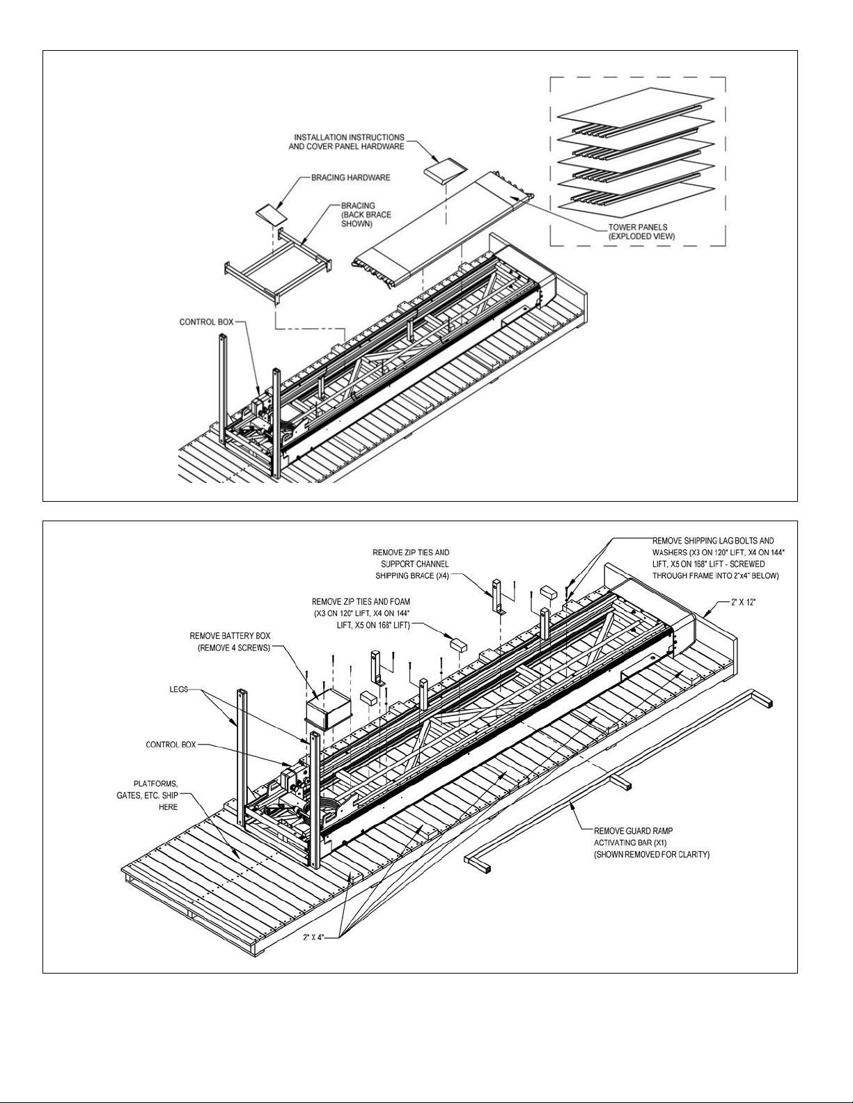
FIG. 1.2
FIG. 1.3
Page | 6
2.
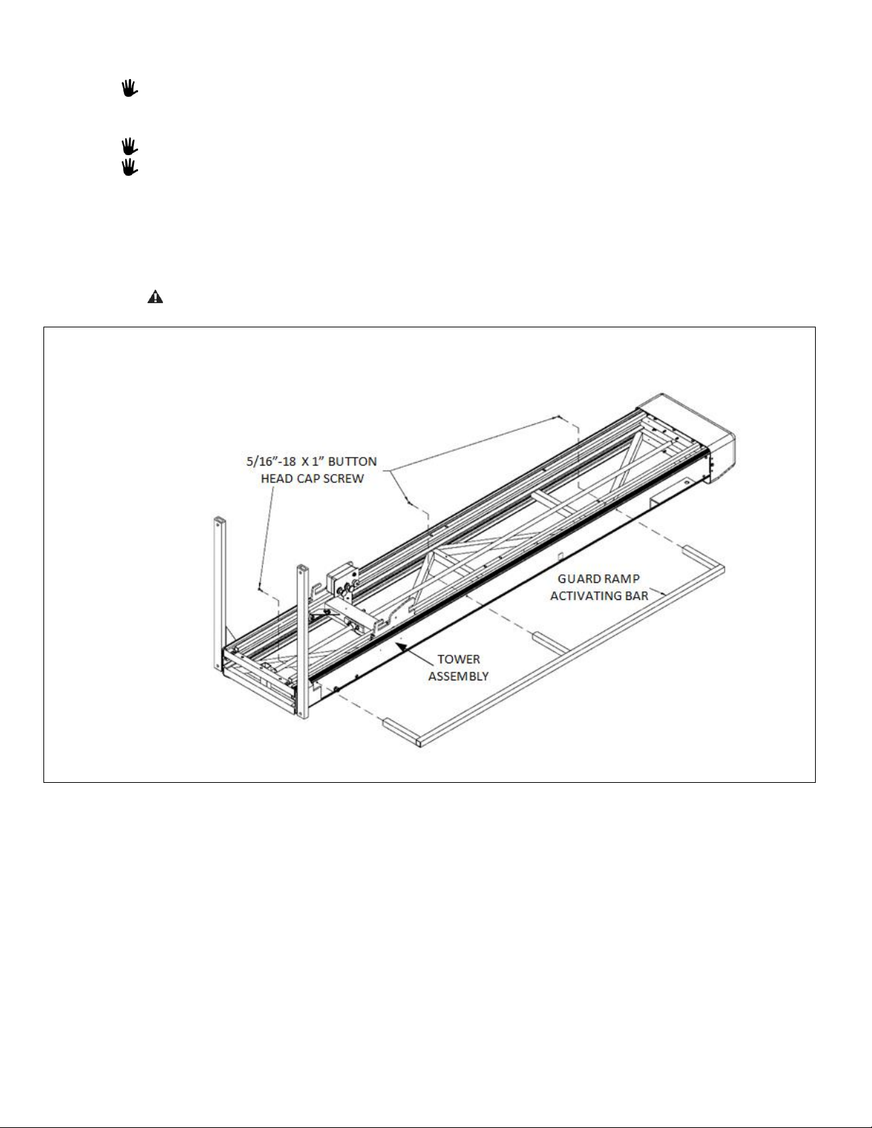
FIG. 2.1
GUARD RAMP ACTIVATING BAR
If you wish to install the Guard Ramp Activating Bar before lifting the VPL into place, go to step 2.1.
Otherwise, refer to the PASSPORT® Vertical Platform Lift (VPL) Installation Manual for Guard Ramp
Activating Bar installation information.
The Guard Ramp Activating Bar must always be installed on the same side as the guard ramp.
The correct Guard Ramp Activating Bar must be used with its intended platform for the guard ramp to
operate correctly. The 90° Turn Platform Guard Ramp Activating Bar extends further from the tower than
the Straight Platform Guard Ramp Activating Bar. The extension for the Straight Platform is approximately
7-7/8” and approximately 12-3/8” for the 90° Turn Platform.
2.1. Attach the Guard Ramp Activating Bar in the three open holes, as shown in FIG. 2.1, on the corresponding side of
the tower using three 5/16”-18 x 1” Button Head Cap Screws (provided). Tighten Button Head Cap Screws
securely.
Do not attempt to lift or move the VPL using the Guard Ramp Activating Bar. Damage will result.
Page | 7
 Loading...