

Page 1

Thank you for choosing
EZ-ACCESS Modular Ramps.
Please visit
www.ezaccess.com
or contact us at 1-800-451-1903
for all of your ramping needs.
INSTALLATION GUIDE
© 2003-2009 HOMECARE PRODUCTS, INC. All rights reserved.
All text and images contained in this document are proprietary and may not be shared, modified, distributed, reproduced, or reused without
the express written permission of EZ-ACCESS, a division of Homecare Products, Inc.
6421 REV A 05-21-09
Proudly made in the USA
Patent Pending
Page 2
INSTALLATION GUIDE
FOR EZ-ACCESS® MODULAR RAMP SYSTEMS
15) FINAL CHECKS:
A) Ensure that all fasteners are in place and secure.
B) Walk on the assembled system, checking for any undue movement.
C) Remove any debris and metal chips.
D) Ensure that the level and slope has not shifted during installation.
E) Check that all handrail ends are covered (either with loops or with end caps).
F) CONGRATULATIONS! Your EZ-ACCESS
®
Modular Ramp System is assembled.
ATTENTION INSTALLER:
• 850 lb. weight capacity
• Read all instructions, including ‘PERIODIC MAINTENANCE AND SAFETY’, prior to
ramp assembly.
• Please leave INSTALLATION GUIDE with the end user.
ATTENTION END USER:
• 850 lb. weight capacity
• Please read and become familiar with the ‘PERIODIC MAINTENANCE AND SAFETY’
section of this manual.
• Fill out and return warranty information.
TOOLS TYPICALLY REQUIRED:
9 ½” SOCKET OR ½" WRENCH
9 9/16” SOCKET OR 9/16” WRENCH
9 5/16” DRILL BIT (IF BRACE ASSEMBLIES ARE USED)
9 ⅛" DRILL BIT
9 5/16” MASONRY DRILL BIT (USED WHEN INSTALLING TO CONCRETE PORCH, STEP, ETC.)
9 5/32” ALLEN WRENCH (SUPPLIED AS NEEDED)
9 3/16” ALLEN WRENCH (SUPPLIED AS NEEDED)
9 #2 PHILLIPS HEAD SCREW DRIVER
9 BOX KNIFE
9 25’ TAPE MEASURE
16) PERIODIC MAINTENANCE AND SAFETY:
A) Caution should be used at all times. Proper maintenance and upkeep to the ramp
surface is vital.
B) IMPORTANT: USE ONLY WITH A QUALIFIED HELPER.
C) Always use your lap belt.
D) It is important that you refer to your equipment’s Owner Guide for the proper
degree of incline/decline and chair direction before attempting ramp use. Never
exceed its recommendations.
E) Periodically check and tighten any loose fasteners to ensure safety.
F) At all times, keep the ramp clear of dirt, leaves, and other debris that may
accumulate on the surface. Simply sweeping the ramp or using a garden hose
will usually suffice, but, if needed, a damp cloth or soft brush with soap and water
can be used (avoid alkaloid detergents
). Rinse well and use extra caution
when the ramp surface is wet.
G) If ramp surface is covered with ice and/or snow, remove before use. Snow
accumulation should be shoveled and the tread surface swept clean. Calcium
Chloride salt substitute may be used to melt snow or ice accumulation on the
ramp, however, after the snow and/or ice threat has cleared, be sure to clean the
tread surface with soap and water (avoid alkaloid detergents
) to remove Calcium
Chloride residue. Rinse well and use extra caution when the ramp surface is
wet.
H) Do not play on or near ramp.
I) Do not use handrails or ramp to support planters, decorations, etc.
J) Ramp surface may become slippery when wet.
K) If any part of the ramp is damaged or loose, DO NOT USE UNTIL REPAIRS
CAN BE MADE BY A CERTIFIED INSTALLER OR OTHER QUALIFIED
PERSON.
— — — — — — — — — — — — — — — — — — — — — — — — — — — — — — — — — — — — — — — — — —
9 HAMMER
9 LEVEL
9 RUBBER MALLET
9 FILE
9 POWER DRILL
9 HACKSAW (FOR OPTIONAL HANDRAIL KITS)
9 DIGGING TOOLS (IF AN OBSTACLE NEEDS TO BE REMOVED)
9 TWO ABLE-BODIED PERSONS NEEDED FOR INSTALLATION
VIEW PACKING LIST: Each ramp system is shipped with a packing list. Be sure to check
that all items and tools are present before starting installation.
- 2 -
WARRANTY REGISTRATION
EZ-ACCESS®, A DIVISION OF HOMECARE PRODUCTS, INC. y 700 MILWAUKEE AVE N y ALGONA WA 98001-7408
TYPE EZ-ACCESS MODULAR RAMP
NAME PHONE
ADDRESS
NAME OF DEALER DEALER’S CITY, ST, ZIP
PRICE DATE PURCHASED
WHERE WILL RAMP BE USED?
WHAT INFLUENCED YOUR PURCHASE OF THIS RAMP?
MANUFACTURED DATE
CITY, ST, ZIP
SEE LABEL ON SIDE OF RAMP
FRIEND RECOMMENDED DEALER RECOMMENDED WEBSITE ADVERTISING/MAGAZINE
OTHER (PLEASE EXPLAIN)
Please mail warranty information within 10 days of purchase.
- 31 -
Page 3

WARRANTY & REGISTRATION
CONTENTS
BASIC SYSTEM COMPONENTS...................................................................... 4-5
INSTALLING PLATFORMS ...................................................................................6
1. EZ-ACCESS, a division of Homecare Products, Inc., (herein referred to as Manufacturer), warrants that the
equipment shall be free from defects in material and workmanship under normal use and service for a
period of 3-years from the date of original purchase. This limited warranty applies to the original purchaser
only and is non-transferable. This limited warranty is applicable to defective metal structure components
only (excludes powder coated finish, applied non-skid tread, etc.) No part of this warranty will apply to any
equipment which has been subject to misuse, vandalism, negligence, alteration, improper loads, accident,
improper installation, or which has been repaired outside Manufacturer’s place of business in any way as in
the reasonable judgment of Manufacturer, to adversely affect its performance and reliability, nor to normal
deterioration due to wear, tear and exposure, corrosion, or damage caused by rain, fire, earthquake or other
natural causes or acts of nature.
2. Manufacturer’s obligation and purchaser’s sole remedy under this warranty is limited to, at Manufacturer’s
option, repairing or replacing equipment which is returned to its place of business and which, upon
examination, shall disclose to Manufacturer’s reasonable satisfaction to have been defective. Manufacturer
will make the repair or replacement of defective components at its own expense. If Purchaser discovers a
defect, he/she must call Manufacturer at 253-249-1101 to request a Return Authorization (RA) to return the
merchandise to Manufacturer.
3. If Manufacturer determines, in its sole discretion, to replace the equipment with either a new or repaired unit,
purchaser shall be responsible for a charge prorated on the following basis: The purchaser will be allowed a
credit against the purchase price of equivalent equipment at the time of return to Manufacturer, in proportion
to the percentage of the warranted service life remaining at the time of such return. Purchaser will be
responsible to pay the balance of the purchase price of equivalent equipment. Manufacturer reserves the
right to require payment prior to delivery of the repaired/replaced equipment. In calculating available credit,
the remaining warranted service life will be rounded up or down to the nearest whole year. YEARS 0-1: Unit
repaired or replaced; YEARS 1-2: Repair or 50% $ credit (current purchase price multiplied by credit
percentage); YEARS 2-3: Repair or 25% $ credit (current purchase price multiplied by credit percentage).
This limited warranty does not cover removal or reinstallation. Manufacturer reserves the right to require
Purchaser to pay for all shipping charges (Government purchases exempt).
4. DISCLAIMER: THE WARRANTIES AND REMEDIES CONTAINED HEREIN ARE EXCLUSIVE AND IN LIEU OF
ALL OTHER WARRANTIES, WHETHER EXPRESS, IMPLIED OR STATUTORY, INCLUDING ANY LIABILITY
ARISING UNDER ANY WARRANTY OF MERCHANTABILITY OR FITNESS FOR A PARTICULAR PURPOSE,
STATUTORY OR OTHERWISE. HOWEVER, THAT IF ANY IMPLIED WARRANTY CANNOT BE DISCLAIMED
IN ANY TERRITORY WHERE A PRODUCT IS SOLD, THE DURATION OF SUCH IMPLIED WARRANTY IS
LIMITED TO THE DURATION OF THE LIMITED WARRANTY DESCRIBED IN THE FIRST PARAGRAPH.
5. MANUFACTURER SHALL NOT BE LIABLE UNDER ANY CONTRACT, NEGLIGENCE, STRICT LIABILITY OR
OTHER LEGAL OR EQUITABLE THEORY FOR ANY DIRECT, SPECIAL, INCIDENTAL OR CONSEQUENTIAL
DAMAGES, RESULTING FROM THE USE, MISUSE OR INABILITY TO USE THE EQUIPMENT, OR ARISING
OUT OF ANY BREACH OF THIS LIMITED WARRANTY, EVEN IF MANUFACTURER HAS BEEN ADVISED OF
THE POSSIBILITY OF SUCH DAMAGES. THE SOLE REMEDY FOR A BREACH OF THE FOREGOING
LIMITED WARRANTY IS REPLACEMENT OF THE DEFECTIVE OR NON-CONFORMING EQUIPMENT OR
PART. THE MAXIMUM LIABILITY OF MANUFACTURER UNDER THIS WARRANTY IS LIMITED TO THE
PURCHASE PRICE OF THE EQUIPMENT COVERED BY THE WARRANTY.
6. Some states do not allow the exclusion or limitation of incidental or consequential damages, so the above
limitation or exclusion may not apply to you. This warranty gives you specific legal rights, and you may also
have other rights which may vary from State to State. Manufacturer reserves the right to change or improve
its products without any obligation to change or improve any Product previously manufactured by it.
INSTALL SADDLE BRACKETS TO PLATFORM ......................................7
CONNECTING TWO PLATFORMS TOGETHER......................................8
ATTACH SUPPORT TUBES TO PLATFORM SADDLE BRACKETS .......9
INSTALL BASE FEET AND ADJUST HEIGHT........................................10
INSTALL PLATFORM BRACE ASSEMBLY ............................................10
INSTALL RAMP SECTIONS.......................................................................... 11-16
INSTALLING A SINGLE RAMP RUN ............................................................ 16-17
ANCHOR TOP TRANSITION PLATE..................................................................18
ANCHOR BOTTOM TRANSITION PLATE..........................................................18
PRE-ASSEMBLE HANDRAILS ...........................................................................19
INSTALLING RAMP HANDRAILS .......................................................................20
INSTALLING PLATFORM HANDRAILS..............................................................21
INSTALLING LOOPS...........................................................................................22
INSTALLING END CAPS.....................................................................................22
OPTIONAL INSIDE CORNER HANDRAIL KIT ............................................. 22-23
CORNER POCKET PROTECTIVE CAP .............................................................23
OPTIONAL HANDRAIL CLOSURE KIT......................................................... 24-25
OPTIONAL TOP SUPPORT ASSEMBLY............................................................26
OPTIONAL LIGHTNING ROD GROUNDING KIT ...............................................27
OPTIONAL HURRICANE TIE DOWN KIT..................................................... 28-29
WARRANTY .................................................................................................. 30-31
FINAL CHECKS...................................................................................................31
- 30 -
PERIODIC MAINTENANCE & SAFETY ..............................................................31
- 3 -
Page 4
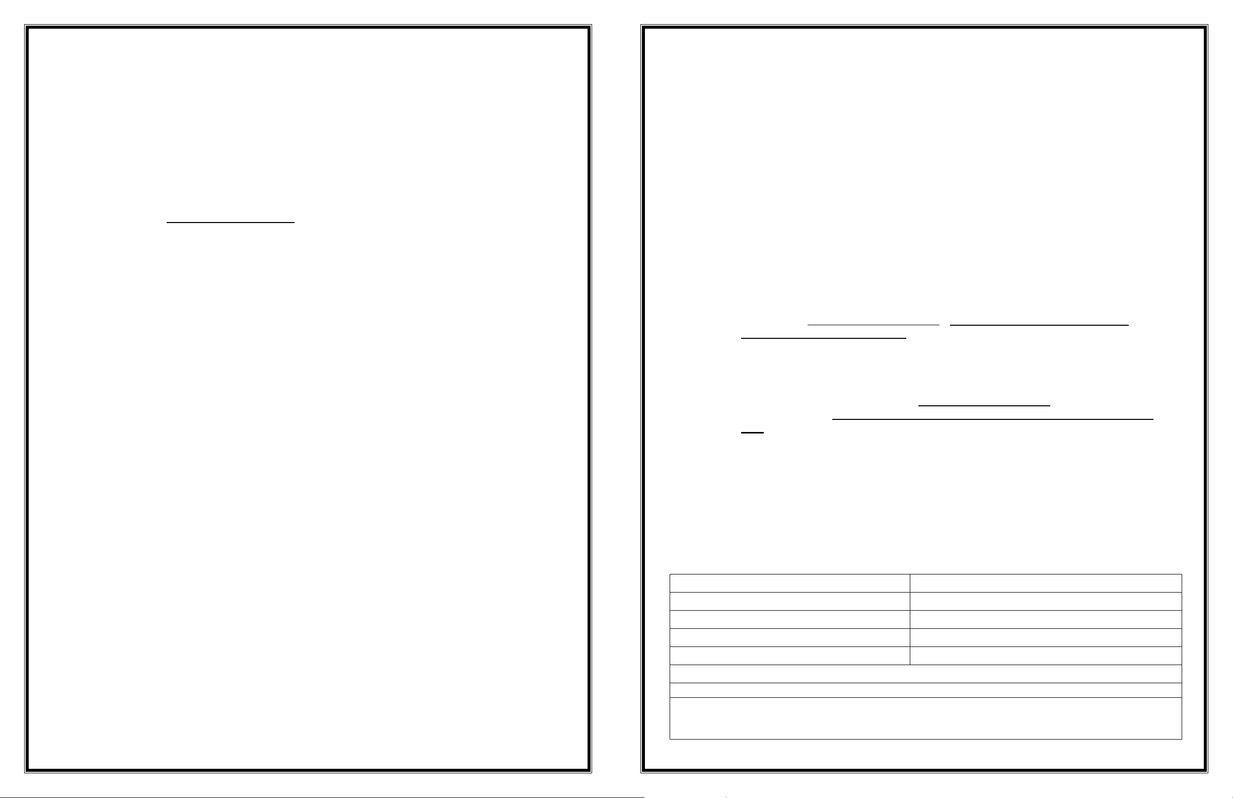
BASIC SYSTEM COMPONENTS: Because each ramp configuration will differ from one
another, your system may or may not contain all of these basic system components:
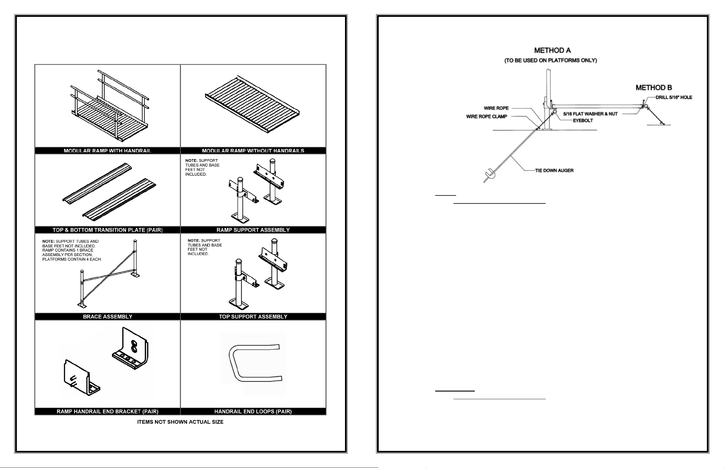
FIG. 44
A) RAMP
i) Refer to FIG. 44, METHOD B.
ii) Install one TIE DOWN KIT per each 10-feet of ramp (e.g., 8' of ramp
requires one TIE DOWN KIT, but 12’ of ramp requires two). See FIG. 43
for acceptable locations.
iii) Drill a 5/16” hole below the tread surface and between the ribs underneath
the treads in each of the side rails at the center of the ramp.
iv) In this drilled hole, install one of the 5/16” eyebolts and secure to the ramp
using one 5/16” flat washer and one 5/16” nut.
v) Install the tie down anchor augers into the ground, inline with the eyebolts
and perpendicular to the ramp at an approximate angle of 30 degrees.
Use a ½” steel rod (or similar item) through the eye of the anchor auger to
turn the anchor auger into the ground. Keep turning the auger until only
the eye is exposed.
vi) Secure one end of the wire rope to one of the eyebolts using the supplied
3/16” wire rope clamps. Thread the other end of the wire rope through the
eye of the anchor auger and secure the wire rope to itself using the
supplied 3/16” wire rope clamps. NOTE: Ensure that the wire rope has
been pulled taut and all slack has been removed prior to securing it to the
anchor auger.
vii) Cut the excess wire rope as required using a cable cutter or other
appropriate tool. Wrap vinyl electrical tape at the cut end to keep the wire
rope from fraying.
viii) Repeat on the opposite side of ramp section.
B) PLATFORM
i) Refer to FIG. 44, METHOD A.
ii) Install one TIE DOWN KIT per Platform.
iii) Install eyebolts by removing the 5/16” x 1½” bolt, then inserting the eyebolt
in its place (see FIG. 43 for acceptable locations).
- 4 -
- 29 -
Page 5

14) INSTALL OPTIONAL HURRICANE TIE-DOWN KIT:
The installer, based on field conditions, will determine the exact location of the tie downs.
As a rule, they should be positioned opposite one another and near the center of ramp as
shown in FIG. 43. (METHOD A, as shown in FIG. 44 is to be used for securing platforms
only.)
The Tie Down Installation Kit meets the requirements of Section 6.0 of ASCE 7-02 (wind
loads) for ensuring that all EZ-ACCESS Ramp systems are properly restrained against
hurricane strength winds.
Install the EZ-ACCESS® Modular ramp system ramp system to establish layout and
locations. It may be necessary to temporarily reposition components in order to install
anchor augers.
WARNING: Prior to installing the anchor augers into the ground, ensure that any
underground electrical conductors, natural gas lines, water/drain lines, and/or other
interferences are located and will not hinder the installation.
WARNING: The tie down installation should be completely inspected for any loose
wire ropes, fasteners, anchor augers, etc. after being subjected to strong winds.
FIG. 43
- 28 -
- 5 -
Page 6

1) INSTALLING PLATFORMS: If your system does not include a platform, skip to ‘INSTALL
RAMP SECTIONS’ of this instruction guide. Generally, we suggest installing all platforms
and ramps before installing handrails (see ‘HANDRAIL INSTALLATION’).
A) There are three types of platforms (you may be installing one or more of these
types). All three require the same procedure for assembly except for FIG. 3
which requires an additional platform connector kit.
FIG. 1 5' x 5' Universal Platform (straight configuration)
FIG. 2 5' x 5' Universal Platform (turn configuration)
FIG. 3 5' x 4' Universal Platform (2 shown combined to make 5' x
8’ turn back platform)
13) INSTALL OPTIONAL LIGHTNING ROD GROUNDING KIT:
A) The Lightning Rod Grounding Kit provides a path for lightning strikes into the
ground.
WARNING: Prior to installing the grounding rod, ensure that any underground
electrical conductors, natural gas lines, water/drain lines, and/or other interferences
are located and will not hinder the installation.
i) Install the EZ-ACCESS
ii) Drive the grounding rod straight into the ground as close as possible (at
®
Modular ramp system.
least within 1½') to one of the support tubes, leaving approximately 2"
exposed.
FIG. 1 FIG. 2
iii) Install the hose clamp around support tube. Place #8 copper wire under
hose clamp and tighten so that wire is in good contact with support tube.
iv) Install 5/8” grounding rod clamp to grounding rod. Place #8 wire between
clamp and rod, then tighten clamp.
FIG. 42
FIG. 3
- 6 -
- 27 -
Page 7

12) INSTALL OPTIONAL TOP SUPPORT ASSEMBLY:
A) The top support assembly provides supplemental support at the upper end of the
ramp. When used, the top support assembly replaces the Ramp Handrail End
Brackets.
i) Attach top support brackets with two each 5/16” x 1½" bolts and two each
5/16” flat washers.
NOTE: There is a left and right top support bracket. The two 3/8” studs
aligned horizontally should be toward the end of the ramp (FIG. 39).
B) The following steps are done AFTER the ramp is resting on a supporting surface
and the top transition plate is installed. IMPORTANT: Read “INSTALLING A
SINGLE RAMP” and “ANCHOR TOP TRANSITION PLATE” sections and ensure
all steps are completed before proceeding with the steps that follow.
i) Install support tube bracket on each top ramp support bracket using two
each 3/8” nylock nuts into the threaded holes and two each 3/8” flat
washers. DO NOT TIGHTEN (FIG. 40).
ii) Install two each 3/8” x ½” hex bolts into the threaded holes on the support
tube bracket.
B) INSTALL SADDLE BRACKETS TO PLATFORM:
i) Place the surface of the platform face down, onto cardboard or a lawn so
that the platform is not damaged (scratched or dented).
ii) Each platform has two different configurations at each corner into which
the platform saddle brackets and support legs can be installed. To account
for obstacles, either position can be used as long as one platform saddle
bracket is installed in each corner.
iii) Position the platform saddle bracket over the threaded inserts located on
each outside corner of the platform (FIG. 4).
iv) Slide the platform saddle brackets into position (one end of the bracket will
slide into the groove). NOTE: If there are space limitations, the saddle
brackets can be installed under the platform as shown in FIG. 7 (if
necessary, support tubes can be cut to fit).
v) Using a ½” socket wrench, attach a platform saddle bracket to the platform
with two 5/16” x 1½” bolts and two 5/16” flat washers. DO NOT OVER
TIGHTEN
(FIG. 5). Repeat this step for all four platform saddle brackets.
NOTE: The 4 x 4, 5 x 4, and 5 x 5 platforms each use 4 (four) platform
saddle brackets.
vi) Once installed, start two each ⅜” x ½” bolts into the threaded holes in each
platform saddle bracket (FIG. 6) in order to secure the support tube.
iii) Slide support tube into support tube bracket and onto base foot.
iv) Level support tube and then tighten 3/8” nylock nuts to secure support tube
bracket (FIG. 41).
v) Adjust height as needed, and then tighten bolts.
vi) Place end caps on support tube.
FIG 7
FIG. 39 FIG. 40 FIG. 41
- 26 -
- 7 -
Page 8

C) CONNECTING TWO PLATFORMS TOGETHER:
i) Place the surface of the platform face down, onto cardboard or a lawn so
that the platform is not damaged (scratched or dented).
ii) Places edges to be joined against one another.
iii) Attach platform connector saddle bracket (two each) into existing threaded
inserts using 5/16” x 1½” hex bolts (four per bracket) and 5/16" flat
washers (four per bracket) as shown in FIG. 8. DO NOT OVER TIGHTEN.
NOTE: Any two platforms with the same width can be connected.
However, generally two 5' x 4’ platforms are connected to make a turn
back platform.
iv) FIG. 9 shows completed assembly. CAUTION: Although platforms are now
connected, four support tubes must be installed per platform.
FIG. 36
FIG. 8 FIG. 9
FIG. 37 FIG. 38
- 8 -
- 25 -
Page 9

11) INSTALL OPTIONAL HANDRAIL CLOSURE KIT:
A) This kit will connect the handrails on a platform to the handrails on one side of
the ramp.
i) If needed, drop square tube post into corner pocket on platform and
tighten two set screws with supplied 3/16” allen wrench (FIG. 33).
ii) Using an adjustable elbow with a threaded insert in one end, pass 5/16” x
2” buttonhead screw through the hole in square tube into threaded insert on
adjustable elbow. Tighten lightly (FIG. 34).
iii) Insert ring joiner into each end of other elbows (FIG. 35).
iv) Insert ring joiner/adjustable elbow assembly into tube end on ramp handrail
and position both assemblies until they are aligned (FIG. 36).
v) Measure the distance between the ring portions of the ring joiner
assemblies. HELPFUL HINT: Use the supplied 5/32” and 3/16” allen
wrenches to lightly tighten the ring joiner/adjustable elbow assembly so they
hold their position while measuring.
vi) Cut round tube to the length measured (FIG. 37).
vii) Using a metal file, smooth any sharp edges from the cutting.
viii) Insert cut tube into place and tighten all setscrews on ring joiners and
adjustable elbows (FIG 38).
NOTE: If difficult to install, disassemble adjustable elbows.
D) ATTACH SUPPORT TUBES TO PLATFORM SADDLE BRACKETS:
i) Tip the platform on its side. Have one person support the platform while the
other person slides the support tubes into the platform saddle brackets.
Adjust the support tubes to the approximate height needed (FIG. 10).
FIG. 34
FIG. 33
FIG. 10
ii) Using a 9/16” socket wrench, secure each of the support tubes with one of
the two bolts on each platform saddle bracket (the second bolt will be
tightened after final height adjustments are complete). The universal
platform configured as a turn back platform (FIG. 3) will have eight tubes to
adjust.
CAUTION: Do not attempt to walk on the platform without both bolts in
each platform saddle bracket tightened securely.
iii) Place the platform with support tubes attached into the upright position.
IMPORTANT: Do not let the weight of the platform bear on the support
tubes while tipping the platform upright as it may bend the outer rail.
FIG. 35
- 24 -
- 9 -
Page 10

E) INSTALL BASE FEET AND ADJUST HEIGHT:
i) Slip the base foot under each support tube (FIG. 11).
NOTE: If installing on soft soil it may be necessary to set the base foot on
a concrete pad or stepping stone.
ii) Adjust the final height of the platform.
a. Adjust each leg one at a time by loosening the bolt in the platform
saddle bracket. Using a level, adjust the platform height and
retighten (FIG. 12).
iii) Once the final height has been adjusted, tighten the second bolt in each
platform saddle bracket.
iv) Ensure that all bolts are secure.
v) Cut round tube to the length measured (FIG. 31).
vi) Using a metal file, smooth any sharp edges from the cutting.
vii) Insert cut tube into place and tighten all set screws on ring joiner/adjustable
elbows assemblies (FIG. 32).
NOTE: If difficult to install, disassemble adjustable elbows and reconfigure.
10) INSTALL CORNER POCKET PROTECTIVE CAP:
A) Some platform configurations will have unused corner pockets on which corner
pocket protective cap will need to be installed (FIG. 32a).
FIG. 31
FIG. 11 FIG. 12
F) INSTALL PLATFORM BRACE ASSEMBLY:
i) Install platform brace assemblies on all support tubes when the walking
surface is 36” or more above the ground. The platform brace assemblies
are normally installed on all four sides (FIG. 13).
ii) Platform brace assemblies need to be cut to desired length and 5/16” holes
to attach the brace bands will need to be drilled at both cut ends.
iii) Ensure that all platform brace assemblies are secured before using
platform.
FIG. 32
FIG. 32a
FIG. 13
- 10 -
- 23 -
Page 11

7) INSTALL LOOPS:
A) Install loops using same procedure as handrail with joiner assemblies.
8) INSTALL END CAPS:
A) Use end caps when there are any remaining open ends on the handrails.
i) Push them in by hand or by using a rubber mallet, then twist caps once
they are in place.
9) INSTALL OPTIONAL INSIDE CORNER HANDRAIL KIT:
A) Because each installation is unique, the components must be cut at the job site.
i) Slide a ring joiner into both ends of the adjustable elbow (FIG. 28).
ii) Slide a ring joiner/adjustable elbow assembly into each ramp handrail tube
(FIG. 29).
iii) Position both assemblies until they are aligned (FIG. 30).
iv) Measure the distance between the two ring portions of the ring
joiner/adjustable elbow assembly.
HELPFUL HINT: Use the supplied 5/32” and 3/16” allen wrenches to
lightly tighten the ring joiner/adjustable elbow assembly so they hold their
position while measuring.
A) INSTALL RAMP SECTION(S):
i) Turn the ramp sections upside down on a flat surface (so that the ramps do
not get scratched or dented, it is recommended that this be done either on
the lawn or on a piece of cardboard).
NOTE: If you are installing a single ramp section, skip to 'INSTALLING A
SINGLE RAMP RUN’.
ii)
iii) Position the two center saddle brackets over the threaded inserts found on
Butt the sections together end-to-end and ensure there is no gap.
the end of each ramp section (FIG. 14).
iv) One edge of the center saddle bracket will slide into the groove of the ramp
section.
NOTE: Ramp sections are connected to create a ramp run using two
interchangeable center saddle brackets per joint. The center saddle
brackets are also where the handrails and support tube brackets are
attached, and are a part of the ramp support assembly. (FIG. 14).
FIG. 28
FIG. 30
FIG. 29
FIG. 14
v) Attach the center saddle brackets using four each 5/16” x 1½” bolts and
washers per center saddle bracket.
vi) Tighten all eight bolts (four each per center saddle bracket).
NOTE: A maximum of three ramp sections may be joined in this manner.
vii) If necessary, install optional top support assembly at this time. See
- 22 -
'OPTIONAL TOP SUPPORT ASSEMBLY'.
- 11 -
Page 12

FIG. 15a FIG. 15b
viii) Install four ramp handrail end brackets (these will be used to attach
handrails in a later step).
a. For 4’, 6’, and 8’ ramps, use one at each outside corner of the
ramp section using one 5/16” x 1½” bolt & washer into the
threaded insert second from the end of the ramp (FIG. 15a).
b. For 10' ramps, two additional ramp handrail end brackets are
installed using one 5/16” x 1½” bolt and washer at the center of
each ramp section (FIG. 15b). NOTE: Ensure holes in ramp
handrail end bracket align with threaded inserts in ramp. Install
one fastener into either of the two inserts.
ix) Turn the joined ramps to the upright position.
x) Place the upper end of the ramp onto the supporting surface, i.e., platform,
porch, etc.
xi) Once the ramp is resting on the porch or platform, lift the upper end of the
ramp and install the top transition plate (top transition plate is the smaller
of the two) into what will be the upper end of the ramp.
NOTE: When used with an MTSA, the bottom transition plate (the larger
of the two) can be installed at what will be the upper end of the ramp to
compensate for minor angular misalignment (about 10 degrees) between
the porch, deck, or platform.
xii) Install the bottom transition plate (larger of the two) into what will be the
lower end of the ramp (FIG. 16).
6) INSTALL PLATFORM HANDRAILS:
NOTE: Depending on your configuration, refer to FIG. 26 and 27, as needed.
i) Drop platform handrails into corner pockets on straight platform
configuration. NOTE: If the handrails do not fit, it may be necessary to
remove the washers between the vertical post and round tubes.
ii) To connect handrails on turn and turn back platform configurations, remove
one vertical post per platform and retain for reuse. Pass three each 5/16” x
2” buttonhead screws through the holes in square post and into threaded
insert in round tube/square tube end. Tighten with supplied 3/16” allen
wrench. If the handrails do not fit in the corner pocket, it may be necessary
to remove/add washers between the vertical post and round tubes.
iii) Tighten two each set screws in each corner pocket on platform with
supplied 3/16” allen wrench.
iv) Use a rubber mallet to install square plastic end caps into the top of
handrail posts.
v) Install plastic protective cap over unused corner pocket.
vi) Using the supplied 3/16” allen wrench, tighten the setscrews on the outside
of the square corner pockets.
NOTE: Straight platform handrails simply drop into the square pockets and
require no assembly other than tightening the set screws (FIG. 26).
FIG. 16
- 12 -
FIG. 26
- 21 -
FIG. 27
Page 13

5) INSTALL HANDRAILS:
A) Install pre-assembled handrail section to side of ramp run (FIG. 22).
i) The vertical posts of the handrails each have two holes that correspond
with studs on the saddle brackets that were installed earlier.
ii) Attach handrails to these studs using two each 5/16” flat washers and two
each 5/16” hex nuts per handrail post.
NOTE: If the studs do not align with the posts and are off by 6”, the Ramp
Handrail End Bracket was installed into the wrong threaded insert on the
ramp. (See FIG. 15a for location of the correct insert).
FIG. 25
a) Maneuver the ramp to its desired position (FIG. 17).
IMPORTANT: Make sure the top transition plate overlaps the supporting surface
as far as possible.
CAUTION: DO NOT use the ramp until all support tubes and ramp brace
assemblies (if needed) are installed and secured!
FIG. 17
- 20 -
xiii) So that no sharp edges are exposed, install protective caps over side rail
corners as shown in FIG. 18. Place one cap on each side at both the top
and bottom of ramp.
NOTE: If necessary, use silicone adhesive to bond cap to ramp.
FIG. 18
- 13 -
Page 14

FIG. 19
xiv) Attach support tube bracket to the center saddle bracket using ⅜” nylock
nuts and ⅜” washers (FIG. 19).
a. To ensure plumb support tubes, level the support tube brackets
(FIG. 20).
b. Secure and tighten the ⅜” nylock nuts.
c. Start two each ⅜” x ½” bolts without washers into the threaded
holes on each support tube bracket. DO NOT TIGHTEN.
4) PRE-ASSEMBLE HANDRAILS:
A) One pair of handrails is required for each ramp section. Handrails are
interchangeable.
B) When used in a multiple ramp run, joiner assemblies are used to connect
handrails together. Refer to FIG. 24 for following steps:
i) One end of the handrail tube is notched to accept the joiner assembly.
Locate the notched end on each upper and lower handrail tube.
ii) Slide joiner assembly into the notched end of handrail tube. Repeat
process for both upper and lower handrail tube.
iii) Slide the next handrail section over the joiner assembly.
iv) Ensure that the tube ends are pushed firmly towards each other.
v) Using the supplied 5/32” allen wrench, tighten setscrews in both joiner
assemblies.
vi) Join all handrails together in this manner.
FIG. 20
FIG. 24
- 14 -
- 19 -
Page 15

2) ANCHOR TOP TRANSITION PLATE: The top transition plate must be anchored to a
substantial surface to assure the ramp will not be dislodged. Use the pre-drilled holes at
each corner of the top transition plate as guides.
A) IF RESTING ON A WOODEN SURFACE:
i) Drill two ⅛” holes into the wooden surface and secure by installing a #10 x
1½” stainless screw and #10 stainless washer into each hole (FIG. 23).
B) IF RESTING ON A CONCRETE SURFACE:
i) Using a marker, transfer the hole locations from the top transition plate to
the concrete surface then remove the top transition plate.
ii) Using a 5/16” masonry bit, drill two 1½” deep holes at the marked surface.
iii) Lightly set lead concrete anchor into holes with a hammer.
iv) Re-attach the top transition plate and align over the drilled holes.
v) Secure the top transition plate by installing a #10 x 1½” stainless screw and
#10 stainless washer into each hole.
C) IF RESTING ON AN ALUMINUM PLATFORM:
i) Drill two ⅛" holes and secure by installing a #10 x 1½” stainless screw and
#10 stainless washer into each hole.
NOTE: If the hole you are drilling is not coming out between two ribs on the
underside of the platform, drill a new ⅛" hole through the top transition plate
and platform in a position that will allow the screws to be installed between
the ribs.
xv) Place a base foot under each support tube bracket, then slide support tube
through the bracket and onto the base foot (FIG. 21).
NOTE: If used on very soft soil it may be necessary to set the base foot on
a concrete pad.
xvi) Adjust the legs one at a time.
a) Raise the ramp sections (at the center saddle bracket) to take any
sag out of the ramp run.
b) Tighten the two bolts in each support bracket.
c) Place end cap on support tube (FIG. 21).
NOTE: Adjusting sections can be accomplished by having someone
sight down the ramp while another person adjusts the ramp height.
IMPORTANT: Ensure that the ramp sections are parallel to each
other. If they are not, it may be difficult to install the handrails.
d) Double check that all bolts are tight, the support tubes are plumb, and
the ramp sections are aligned parallel to one another.
FIG. 23
3) ANCHOR BOTTOM TRANSITION PLATE:
A) If the bottom transition plate (end of ramp system) is resting at ground level, then
anchoring the ramp is optional.
B) If a bottom transition plate is resting on any type of raised area (i.e., a platform),
it must be anchored using the same procedures as used to ‘ANCHOR TOP
TRANSITION PLATE’.
- 18 -
FIG 21
- 15 -
Page 16

e) If the ramp tread surface is over 36” in height, connect the brace
assembly under the ramp as shown in FIG. 22.
f) The brace assembly ends will need to be cut to desired length, and
5/16” holes to attach the brace bands will need to be drilled at both
cut ends.
g) Ensure that all platform brace assemblies are secured before using
platform.
FIG 22
iii) Turn the ramp over to the upright position.
a) Place the upper end of the ramp onto the supporting surface, i.e.,
platform porch, etc.
iv) Once the ramp is resting on the porch or platform, lift the upper end of the
ramp and install the top transition plate into what will be the upper end of the
ramp and the bottom transition plate into what will be the lower end of the
ramp (FIG. 16).
NOTE: The bottom transition plate is the larger of the two.
a) Maneuver the ramp to its desired position (FIG. 17).
FIG. 16
H) INSTALLING A SINGLE RAMP RUN:
i) Turn the ramp section upside down on a flat surface. Do this on cardboard
or a lawn so that the ramp is not damaged (scratched or dented).
ii) Install four ramp handrail end brackets (these will be used to attach handrails
in a later step).
a) For 4’, 6’, and 8’ ramps, use one at each outside corner of the ramp
section using one 5/16” x 1½” bolt & washer into the threaded insert
second from the end of the ramp (FIG. 15a).
b) For 10' ramps, two additional ramp handrail end brackets are installed
using one 5/16” x 1½” bolt and washer at the center of each ramp
section (FIG. 15b).
NOTE: Ensure holes in ramp handrail end bracket align with threaded
inserts in ramp. Install one fastener into either of the two inserts.
FIG. 17
FIG. 15a FIG. 15b
- 16 -
- 17 -
 Loading...