

EZ-ACCESS CONCIERGE Series, CONCIERGE 23JL Installation Manual

Manufactured in the USA
1-YEAR WARRANTY. Please register at www.ezaccess.com/warranty-satisfaction.
© Homecare Products, Inc. All rights reserved. All text and images contained in this document are
proprietary and may not be shared, modified, distributed, reproduced, or reused without the express
written permission of EZ-ACCESS®, a division of Homecare Products, Inc.
14903 REV 11-09-15
Installation Manual
CONCIERGE™ Power Door Opener
Model No. CONCIERGE 23JL

Page | 2
U.S. Patent 7,418,8000 B1
Standard Parts List for CONCIERGE 23JL
Residential Jamb Mount Opener (Left Swing)
IMAGE
DESCRIPTION
QTY
CONCIERGE 23JL(MOTOR UNIT)
WITH SLIP FRICTION CLUTCH ARM,
ADJUSTABLE FOREARM AND SHOE, 9-FT
115VAC POWER CORD, AND 300mhz
RADIO RECEIVER WARNING: DO NOT
HANDLE CONCIERGE 23JL BY POWER
CORD.
1
DOUGHNUT MAGNET (PART NO. 2440)
1
#10 1-1/2” WOOD SCREWS
(4) –ATTACHING MOTOR UNIT TO DOOR
(2) –ATTACHING ARM SHOE TO JAMB
6
BINDING BOLTS
FOR ATTACHING UNIT TO DOOR WITH
THROUGH HOLES IN DOOR. (THESE ARE
USED IN PLACE OF THE WOOD SCREWS.)
4
BLANK LATCH PLATE
USED IN PLACE OF ELECTRIC STRIKE
1
DOOR STOP
MOUNTED ON DOOR HINGE
1
Page | 3
U.S. Patent 7,418,8000 B1
Optional Accessories List for CONCIERGE 23JL
Residential Jamb Mount Opener (Left Swing)
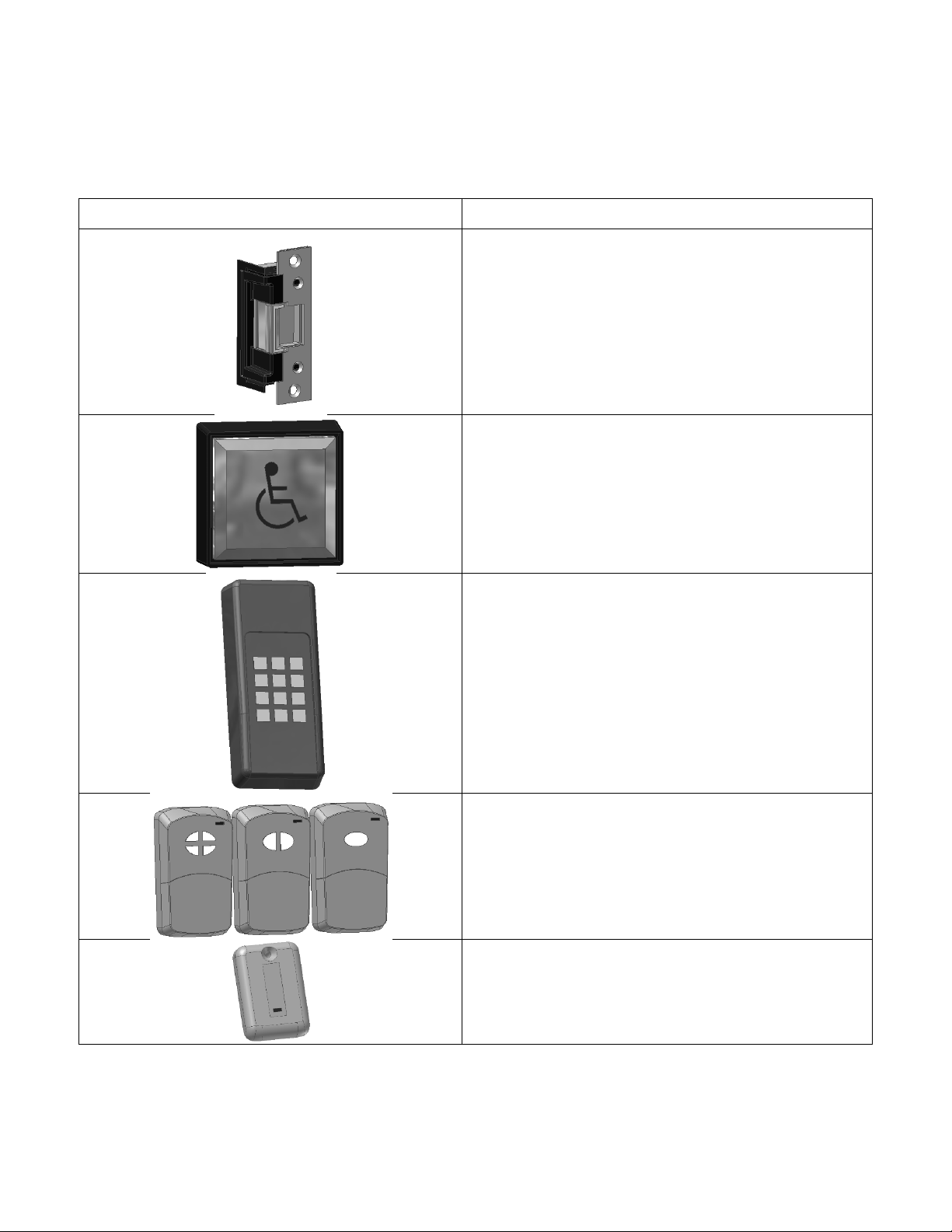
IMAGE
DESCRIPTION
CONCIERGE ESP
24VDC ELECTRIC STRIKE AND FACE PLATE
CONCIERGE PIM
WALL MOUNTED 4.5” SQUARE PUSH PAD
CONCIERGE KEM
WIRELESS PROGRAMMABLE KEYLESS ENTRY
SYSTEM
GARAGE DOOR STYLE TRANSMITTER
CONCIERGE RGD1 – SINGLE CHANNEL
CONCIERGE RGD2 – TWO CHANNEL
CONCIERGE RGD4 – FOUR CHANNEL
CONCIERGE RP1 – SINGLE CHANNEL
PENDANT STYLE TRANSMITTER

Page | 4
U.S. Patent 7,418,8000 B1
TABLE OF CONTENTS
Precautions and Requirements ....................................................................................................... 5
Door Stop ........................................................................................................................................ 6
Mounting the Motor and Lever Arm Shoe ........................................................................................ 7
Lever Arm Adjustment ..................................................................................................................... 8
Electric Strike Installation ................................................................................................................ 9
Programming the Receiver ............................................................................................................ 11
Operation ...................................................................................................................................... 12
Adjustments .................................................................................................................................. 13
Changing Hand (Rotation of the Motor) ......................................................................................... 14
Main Circuit Board Features .......................................................................................................... 15
Troubleshooting ............................................................................................................................. 16
Available Configurations ................................................................................................................ 17

Page | 5
U.S. Patent 7,418,8000 B1
1. PRECAUTIONS AND REQUIREMENTS
1.1. Precautions
1.1.1. Verify that you have the correct model number for your application. Reference model configurations
(page 17) to verify you have the correct unit. If not, see changing hand direction (page 14).
1.1.2. The door that the Concierge 23JL is to be mounted above should be plumb, square, and not warped.
The door should not stick to the jamb.
1.1.3. The door that the Concierge 23JL unit is to be mounted above should have standard butt hinges, void of
any springs. No other door open or close assist features should be attached to the door. 20 lbs. Of initial
force is applied at the leading edge of the door to begin the opening and closing actions. Flimsy or
improperly installed hinges may prevent the door opener from operating properly.
1.2. Power Requirements
1.2.1. This model is supplied with a 9 foot power cord that plugs into a 115v AC outlet. When the optional
electric strike is provided, it is supplied with 12 feet of low voltage wire to connect the electric strike plate
to the strike terminals on the main circuit board (page 11). The terminals are universal. WARNING: Use
caution and disconnect power when wiring electric strike.
1.3. Clearance Requirements
1.3.1. At least 6” of clearance above the top of the door is needed.
HINGE SIDE OF DOOR
6” MINIMUM CLEARANCE FROM TOP EDGE OF DOOR TO CEILING

Page | 6
U.S. Patent 7,418,8000 B1
2. DOOR STOP
2.1. Door Stop Installation: A hard door stop must be used to prevent the door from traveling past 90 degrees when
opening. A hinge mounted standard duty door stop is included in the Concierge 23DR package. To install this
door stop remove the hinge pin from the top door hinge. Reinsert the pin with the door stop in place. Adjust the
threaded post so the door stops at 90 degrees when open. NOTE: A heavy duty door stop (not included) is
recommended for heavier doors.
2.1.1. Remove the hinge pin.
2.1.2. Align door stop through hole.
2.1.3. Re-insert pin.
2.1.4. Adjust threaded post so door does not open past 90 degrees.
Page | 7
U.S. Patent 7,418,8000 B1
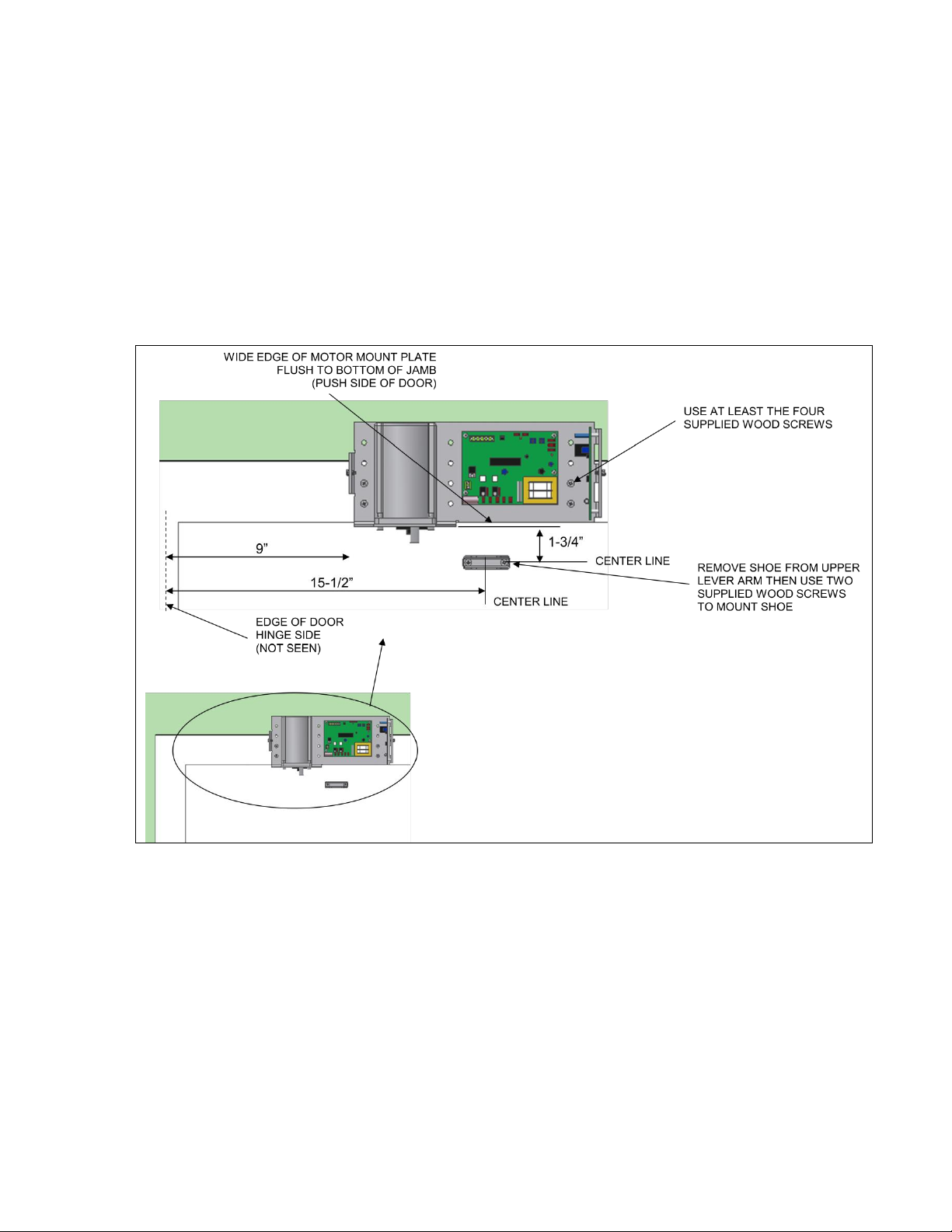
3. MOUNTING THE MOTOR UNIT AND LEVER ARM SHOE
3.1. Mounting the Motor Unit
WARNING: Wear safety goggles prior to drilling. With the wide edge of the motor mount plate flush to the
bottom of the jamb and 3 inches from the edge of the door, secure the mount plate with at least the 4 supplied
wood screws or binding post screws. Any holes in the mount plate may be used but it is advised to use the holes
in the outermost rows to follow best practice technique. Screw into door surfaces that are flush to the back side
of the motor mount plate. It is important the screws achieve a solid mount.
3.2. Mounting the Shoe
First, remove the shoe from the lower lever arm. With the center line of the shoe 1.75 inches below the bottom of
the narrow edge of the motor mount plate and 16 inches from the hinge side edge of the door, secure the shoe to
the door with 2 supplied wood screws.
 Loading...