

EZ EZ-220, EZ-220V, EZ-420 Hardware Manual

x
TABLE OF CONTENTS
Text Panel Hardware ManualTe
Table of Contents
WARNING/Caution ................................................................... inside cover
Table of Contents...........................................................................................i
EU Information ..........................................................................................iv
1 INTRODUCTION
Manual Organization ...............................................................................2
Introduction to the EZSeries Text Panel ..................................................4
What you need to get started ..................................................................5
Hardware ..........................................................................................5
Software ...........................................................................................5
Need Help? ...........................................................................................5
Onscreen HELP ................................................................................5
PLC HELP.........................................................................................5
Technical Support .............................................................................6
Models ...........................................................................................6
PLCs Supported by EZSeries Text Panels ..............................................8
PLC and Programming Cable Part Numbers ..........................................9
Accessories and Optional Equipment .....................................................9
Front Panel Features ............................................................................10
Operator Controls and Indicators ....................................................10
Annunciator Lamps...................................................................11
Data Entry (Keypad) Pushbuttons ............................................11
PLC Message LED ...................................................................11
Control Pushbuttons .................................................................12
Function Pushbuttons ...............................................................12
Pushbutton LEDs......................................................................12
Character LCD Display with LED Backlight ..............................12
Messages .................................................................................13
Rear Panel Indicators............................................................................13
Specifi cations ........................................................................................14
2 HARDWARE INSTALLATION
Custom Labels ......................................................................................16
Create Custom Labels ....................................................................16
Install Custom Labels .....................................................................16
EMI Noise Filter Installation ..................................................................18
Mounting .........................................................................................19
Models EZ-220, EZ-220V, & EZ-420 Outline
Dimensions and Mounting Template .......................................19
Models EZ-220P & EZ-220PV Outline Dimensions
and Mounting Template ............................................................20
Model EZ-220L Outline Dimensions
i

Text Panel Hardware Manual
and Mounting Template ............................................................21
DIN Clip Mounting ...........................................................................22
Connections and Wiring ........................................................................23
EZ-220, EZ-220V & EZ-420 Rear View ..........................................24
EZ-220P & EZ-220PV Rear View ...................................................25
EZ-220L Rear View .........................................................................26
Power Connector ............................................................................27
Serial Port .......................................................................................27
Connect a PLC ...............................................................................28
3 LEARNING THE FEATURES
Learning the Features ...........................................................................30
Memory Mapping/PLC Data Registers..................................................30
Pushbuttons ....................................................................................31
LEDs .........................................................................................31
Annunciator Lamps .........................................................................32
PLC Message Registers .................................................................33
Embedded Data Registers ..............................................................33
PLC Messages and Local Messages ....................................................35
Embedded Data ..............................................................................35
Message Types ...............................................................................36
Displaying PLC Messages ..............................................................36
PLC Message LED .........................................................................35
Arrow Adjustment Entry ..................................................................38
Numeric Keypad Entry ....................................................................38
Annunciator Lamps .........................................................................38
PLC Message LED .........................................................................38
Displaying Local Messages ............................................................39
Local Message File Structure Example ..........................................40
Local Message Menu Structure Example .......................................41
4 TUTORIAL
EZSeries Text Panel Setup ...................................................................44
SETUP Mode ..................................................................................44
Adjust Display Contrast ..................................................................44
Internal Software and Hardware Revisions ....................................44
Preparing for Confi guration .............................................................44
Installing EZSeries Text Panel Programming Software .........................45
Tutorial — Plan the Project using Application Worksheets ...................47
Tutorial — Create the Project using EZSeries Text Panel Programming
Software .........................................................................................51
Tutorial — Confi gure a PLC ..................................................................60
5 CONFIGURATION
Confi gure New System .........................................................................64
ii

Text Panel Hardware ManualTe
x
Confi gure Existing System ....................................................................79
Connect to Panel, View Panel Status and Firmware Version ...............80
Upgrade Firmware ................................................................................81
6 MAINTENANCE and TROUBLESHOOTING
Maintenance .........................................................................................86
Fuse Reset .....................................................................................86
Precautions .....................................................................................86
Screen Overlay/Chemical Compatibility .........................................86
Screen Overlay Cleaning ................................................................88
Gasket Replacement ......................................................................88
Troubleshooting ....................................................................................89
Panel Confi guration Problems ........................................................89
PLC Errors ......................................................................................90
Still Need Help? ....................................................................................91
Warranty Repairs ..................................................................................92
Out of Warranty Repairs .......................................................................92
Frequently Asked Questions (FAQs) .....................................................93
Appendix A .......................................................................................A-1
EZSeries Text Panel Application Worksheet .................................A-2
Appendix B .......................................................................................B-1
Allen-Bradley ..........................................................................B-2
Direct Logic.............................................................................B-3
General Electric ......................................................................B-6
Mitsubishi ................................................................................B-6
Modicon Modbus ....................................................................B-7
Omron .....................................................................................B-8
Siemens..................................................................................B-8
Control Techniques .................................................................B-9
Control Technology Corporation (CTC) ................................B-10
Texas instruments.................................................................B-10
Idec .....................................................................................B-12
Aromat ..................................................................................B-13
EZAutomation EZPLC ..........................................................B-13
Appendix C .......................................................................................C-1
PLC Driver Error Messages ..........................................................C-2
EZSeries Text Panel Error Messages .........................................C-14
EZSeries Text Panel Programming Software Error Messages ...C-15
INDEX ........................................................................................ I-1
iii

Text Panel Hardware Manual
EU INFORMATION
EU Information
The EZ Series Text Panel is manufactured in compliance with European Union (EU) Directives and
carries the CE mark. The EZ Series Text Panel has been tested under CE Test Standard #EN55011,
and is listed under UL File #E209355. The following information is provided to comply with EU documentation requirements.
Please NOTE: Products with CE marks perform their required functions safely
and adhere to relevant standards as specifi ed by EU Directives provided they are
used according to their intended purpose and that the instructions in this manual
are adhered to. The protection provided by the equipment may be impaired if
this equipment is not used in accordance with this manual. Only replacement
parts supplied by EZAutomation or its agents should be used.
Technical
Support
SELV Circuits
Environmental
Specifi cations
Preventative
Maintenance
and Cleaning
If you need assistance, please call our technical support at 1-877-774-EASY or
FAX us at 1-877-775-EASY.
All electrical circuits connected to the communications port receptacle are rated
as Safety Extra Low Voltage (SELV).
Operating Temperature ...................................................................0 to 45 °C
Storage Temperature ................................................................–20 to +60 °C
Operating Humidity .........................................10–95% R.H., noncondensing
Air Composition ..............................................No corrosive gases permitted
No preventative maintenance is required. The EZ Series Text Panel overlay
should be cleaned as needed with warm, soapy water. See Chapter 6, Maintenance and Troubleshooting, for a list of compatible/incompatible chemicals
and compounds.
iv

1
Introduction
In this chapter....
— Manual Organization
— Introduction to the EZSeries Set Point Display Set
Point Display Panel
— What you need to get started
— Need HELP?
— Models
— PLCs Supported by EZSeries Set Point Display Set
Point Display Panel
— Accessories and Optional Equipment
— PLC and Programming Cable Part Numbers
— Front Panel Features

Manual Organization
This manual is all you’ll need to get the EZSeries Set Point Display Set Point
Display Panel installed and confi gured. This manual covers models EZ-220,
EZ-420, EZ-220L, EZ-220P, and two new models with Vacuum Fluorescent
Display EZ-220V, EZ-220PV.
In this manual we will take you through the steps necessary to get your EZSeries
Set Point Display Set Point Display Text Panel up and running in the shortest
possible time. Although your familiarity with programmable operator interface
devices will determine how quickly you move through the steps — it’s as easy
as 1 — 2 — 3. This manual is arranged in chapters. A description of key
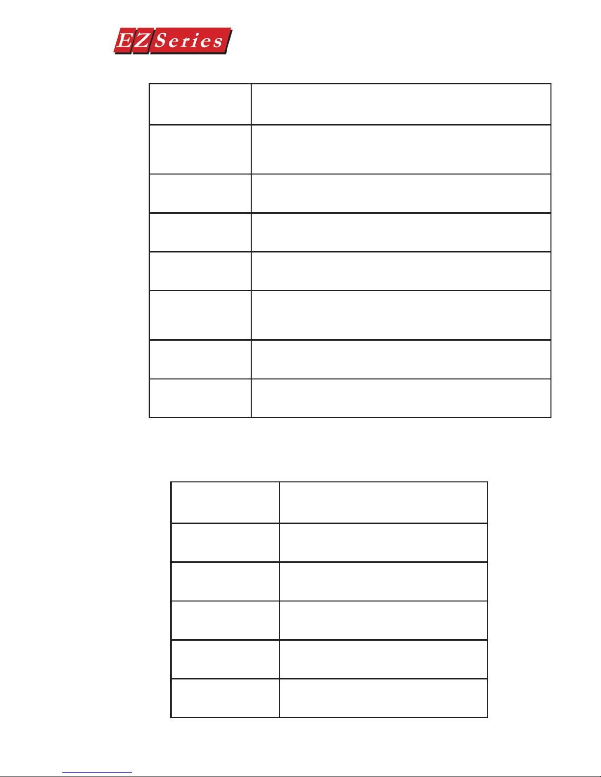
Chapter Description
Introduction
1
Provides Manual Organization, and lists what you need to get started, hardware and software. Discusses how to get help with questions or problems you
might encounter through Onscreen Help and Technical Support. Provides you
with a table listing the various models, their part numbers and special features. Lists the important features of all EZSeries Set Point Display Set Point
Display Panels. Lists the PLCs supported by the panels, by brand, model and
protocol. Lists the part numbers for PLC cables and the programming cable.
Tells how to install programming software.
Text Panel Hardware Manual
2
3
4
Hardware Installation
Provides instructions on how to install custom labels and the EMI Noise Filter.
Discusses two mounting techniques — stud mounting and DIN clip mounting. Provides Outline Dimensions and Mounting Template. Provides you with
instructions on connecting the unit to power, a programming PC and a PLC.
Learning the Features
Provides an Overview of the panel features. Front Panel Features, including;
Function Pushbuttons/LEDs, Character LCD Display, PLC Message LED and
Control Pushbuttons are discussed. Local and PLC Messages are described,
along with types of Messages and Embedded Data Variables (DATA 1, 2, and
3).
Tutorial
Provides instructions to create an example (or “demo”) project. Discusses
how to confi gure a PLC ladder logic program to use with the demo project.
Takes you through the steps necessary to create an EZSeries Set Point
Display Set Point Display Panel project using the programming software and
application worksheets. Shows you how to transfer a project to the panel.
Confi guration
2
EZ-TEXT-M-E
Chapter Description
Step-by-step instructions for confi guring the EZSeries Set Point Display Set
5
6
Point Display Panel (new system) using the EZSeries Set Point Display Set
Point Display Panel Programming Software are provided.
Maintenance and Troubleshooting
Instructions for maintaining the EZSeries Set Point Display Set Point Display
panels are provided, including; Fuse Reset, Precautions, Chemical Compatibility, Cleaning, and Gasket Replacement. Troubleshooting section aids in
diagnosing problems you might encounter when installing or operating the
panel. Provides steps to take to isolate and correct problems.
Text Panel Hardware Manual
INTRODUCTION
A
B
C
Appendix A
Application Worksheets are provided to help you plan and implement your
system confi guration.
Appendix B
Wiring diagrams for several PLC cables are provided.
Appendix C
Error Messages for PLC Drivers, EZSeries Set Point Display Set Point Display Panel, and EZSeries Set Point Display Set Point Display Panel Program-
EZ-TEXT-M-E
3

Text Panel Hardware Manual
Introduction to the EZSeries Set Point Display Set Point Display
The EZSeries Set Point Display Set Point Display Panels provide a man-machine
interface to your PLC automation system. The panels provide features such
as 5 user-defi ned pushbuttons with LED indicators, arrow adjust buttons, and
a built-in menu system. The panels communicate with a PLC using either RS232C or RS-422A/485A serial communication. Confi guration software and panel
programming are covered in chapter 5 of this manual.
The panels allow you to confi gure up to 256 20-character text strings confi gured
as PLC Messages and Local Messages. Local Messages are internal panel
messages that the operator can scroll in a menu tree hierarchy . PLC Messages
are displayed when prompted from the PLC program. A PLC Message LED
illuminates whenever a PLC Message is being displayed. Either message type
can have up to three embedded data variables, one of which can be edited by
using the arrow adjust buttons.
The panels have sealed membrane function pushbuttons that allow you to trigger
PLC actions with the push of a button. These pushbuttons are used for input
signals to the PLC. Each pushbutton can be confi gured to function as one of
three switch types:
• ALTERNATE—keeps its current state until the button is pushed
again
• MOMENTARY— is activated only while the button is being pushed
• PANEL SET AND PLC RELEASE —sets a bit in the PLC when
pressed and is reset by either the PLC program or by pressing the
button again.
The LCD display window supports two or four message lines that can display
up to 20 characters each. The messages are programmed using the EZSeries
Set Point Display Set Point Display Panel Programming Software. The message
control type may be either static—text displays that have NO embedded data,
dynamic —text messages that include embedded data (READ access only), or
interactive —text messages that allow the operator to enter data, or change
values that are stored in the PLC registers (READ/WRITE access).
The EZSeries Set Point Display Set Point Display Panel is available in a variety
of models to suit your application. Key features are provided on page 10.
4
EZ-TEXT-M-E

Text Panel Hardware Manual
What you need to get started
Hardware
• EZSeries Set Point Display Set Point Display Panel (Models EZ-220,
EZ-220V, EZ-220L, EZ-420, EZ-220P, & EZ-220PV)
• 24 Volt DC Power Supply (FA-24PS recommended)
• RS-232C Programming Cable (P/N EZTEXT-PGMCBL)
• Appropriate PLC Cables (see page 9 for part numbers)
• Programmable Logic Controller (PLC)
• PC requirements:
— IBM or compatible PC (486 or better) with a mouse
and separate serial port
— VGA display with at least 800 x 600 resolution (1024 x 768
recommended)
— Standard Windows 95/98 (Second Edition)/NT4.0/2000
requirements
— CD ROM Drive
INTRODUCTION
®
Need HELP?
Software
• EZSeries Set Point Display Set Point Display Panel Programming
Software (P/N EZ-TEXTEDIT-E)
PLEASE NOTE: Chapter 6, Maintenance and Troubleshooting, should be
able to help you with most problems you might encounter.
Onscreen HELP
One of the most important features of the EZSeries Set Point Display Set Point
Display Programming Software is the availability of context sensitive onscreen
help. To access the Help windows, simply press the F1 function key while on
the topic where you need help. For example, if you need help while working with
panel confi guration, hit the F1 function key when that dialog box is open and a
pop-up HELP window will be displayed.
PLC HELP
If you need help with the PLC to EZSeries Set Point Display Set Point Display
Panel Interface, consult the EZSeries Set Point Display Set Point Display Panel
Programming Software Help. Each PLC Driver has a Help Topic that lists the
error messages and provides an explanation for each. Also provided are PLC
EZ-TEXT-M-E
5
Models
Text Panel Hardware Manual
to EZSeries Set Point Display Set Point Display Te Panel wiring diagrams.
Technical Support
Although most questions can be answered with EZSeries Set Point Display Set
Point Display Panel HELP or the manuals, if you are still having diffi culty with a
particular aspect of installation or system design, technical support is available
at 1-877-774-EASY, Monday through Friday, 6a.m. to Midnight CST, or FAX us
The EZSeries Set Point Display Text Panels provide a low-cost, easy-to-use
operator interface alternative for your PLC system. With easy to confi gure
Windows-based software and simple installation, you can be connected and
running in minutes. If your application requires pushbuttons, LEDs, or text
display , but your budget is low , check out the complete line of EZSeries Set Point
Display Text Panels. The following features are common to the EZSeries Set
Point Display Text Panel models shown below:
• stores up to 256 20-character messages
• 5 user-defi ned function pushbuttons and LEDs
• 4 control pushbuttons
• up to three embedded PLC data variables per message
• built-in menu system
• EMI fi ltered power supply to reduce communication problems
Part Number
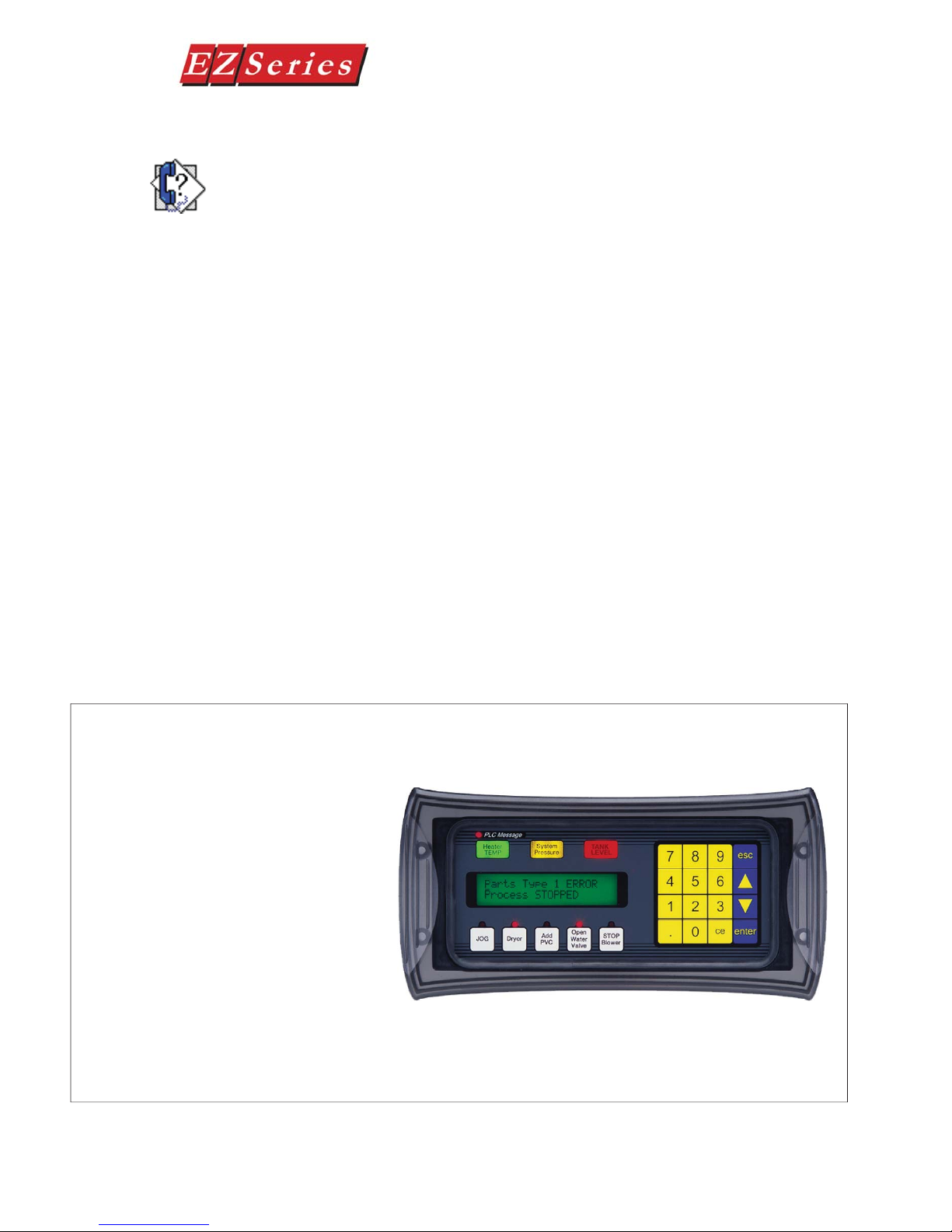
EZ-220P
2 line by 20 character LCD display
Five user-defi ned buttons and LEDs
Numeric keypad
Scroll data entry
Three tri-color LED annunciators
Built-in menu system
EMI fi ltered power supply reduces
communication problems
Character Height 5.55mm (0.22”)
External Dimensions are 10.018” x 5”
****
EZ-220PV
Above with Vacuum Flourescent
Display
6
EZ-TEXT-M-E
FFFFFFEREBVEBEV
Text Panel Hardware Manual
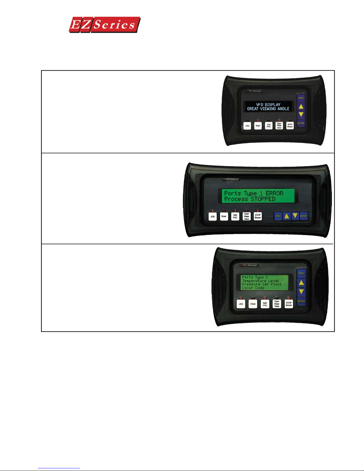
Part Number
EZ-220V
2 lines by 20 characters Vacuum Flourescent Display
Character height of 0.22” (5.55 mm)
External dimensions are 5” x 7.4” x 1.6”
EZ-220
Above with Vacuum with LCD Display
EZ-220L
2 lines by 20 characters LCD display
Character height 0.316” (8.06 mm)
External dimensions are 5” x 10” x 1.6”
INTRODUCTION
EZ-420
4 lines by 20 characters display
Character height of 0.187” (4.75 mm)
External dimensions are 5” x 7.4” x 1.6”
EZ-TEXT-M-E
7
Text Panel Hardware Manual
PLCs Supported by EZSeries Set Point Display Set Point
PLC Brand Model Protocols Supported
Allen Bradley
Aromat Aromat Mewtocol COM
Control Techniques Unidrive 4-wire Binary
Control Technology Corporation (CTC) CTC 2600, 2700, and 5100 CTC Binary
EZAutomation EZPLC EZ Protocol
General Electric 90/30 and 90/70 Versamax SNPX
Idec Idec Computer Link
Mitsubishi FX Series (all) Direct
Modicon
Omron C200, C500, CQM1, CPM1 Host Link
Direct Logic
Siemens Siemens S7300/400 PLCs MPI Adaptor 3964R
Texas Instruments TI5x5 Series, TI505, TI545-1102, TI545-1104
MicroLogix 1000/1200/1500, SLC500, 5/03, /04, and PLC5 DF1 Hlaf Duplex; DF1 Full Duplex
PLC 5 DF1
984 CPU, Quantum 113 CPU, AEG
Modicon Micro Series 110, CPU: 311-xx
411-xx, 512-aa, 612-xx
DL05, DL06
DL105 K-Sequence
D2-230 K-Sequence
D2-240 K-Sequence; DirectNet
DL205
DL305
DL405
D2-250/D2-250 - 1/260
D2-240/250/260 w/DCM DirectNet
D3-330/330P DirectNet
D3-340 DirectNet
D3-350
D3-350 w/DCM DirectNet
D4-430 K-Sequence; DirectNet
D4-440 K-Sequence; DirectNet
D4-450
All with DCM DirectNet
Entivity (Think-n-Do) ModBus RTU
Modbus RTU
K-Sequence; DirectNet;
Modbus (Koyo addressing)
K-Sequence; DirectNet;
ModBus (Koyo addressing)
K-Sequence; DirectNet;
ModBus (Koyo addressing)
K-Sequence; DirectNet
ModBus (Koyo addressing)
TBP (Transparent Byte Protocol) or NITP (NonIntelligent Terminal Protocol)
8
EZ-TEXT-M-E
Text Panel Hardware Manual
INTRODUCTION
PLC Cables and Programming Cable Part Numbers
Part Number Cable Description
EZP-2CBL
EZP-2CBL-1 Direct Logic (VGA Style) 15-pin port, DL250 (RS-232C)
EZP-3CBL Direct Logic PLC RJ11 port, DL340 (RS-232C)
EZP-4CBL-1 Direct Logic PLC 15-pin Dsub port, DL405 (RS-232C)
EZP-4CBL-2
EZP-90-30-CBL GE 90/30 and 90/70 15-pin Dsub port (RS-422A)
EZP-SLC-232-CBL AB SLC 5/03/04/05 DF1 port (RS-232C)
Direct Logic PLC RJ12 port, DL05, DL105, DL205, DL350 & DL450
(RS-232C)
Direct Logic PLC 25-pin Dsub port, DL405, DL350, DL305 DCU, and all
DCM’s (RS-232C)
Accessories and Optional Equipment
Part Number Description
EZ-TEXTEDIT-E EZ Series Text Panel Programming Software
EZ-TEXT-S-GSK Standard Replacement Gasket (small)
EZ-TEXT-L-GSK Standard Replacement Gasket (large)
EZ-BRK-2 DIN Clips (package of 4)
EZ-TEXT-STUDS Mounting Studs (package of 4)
EZ-TEXT-M-E
9
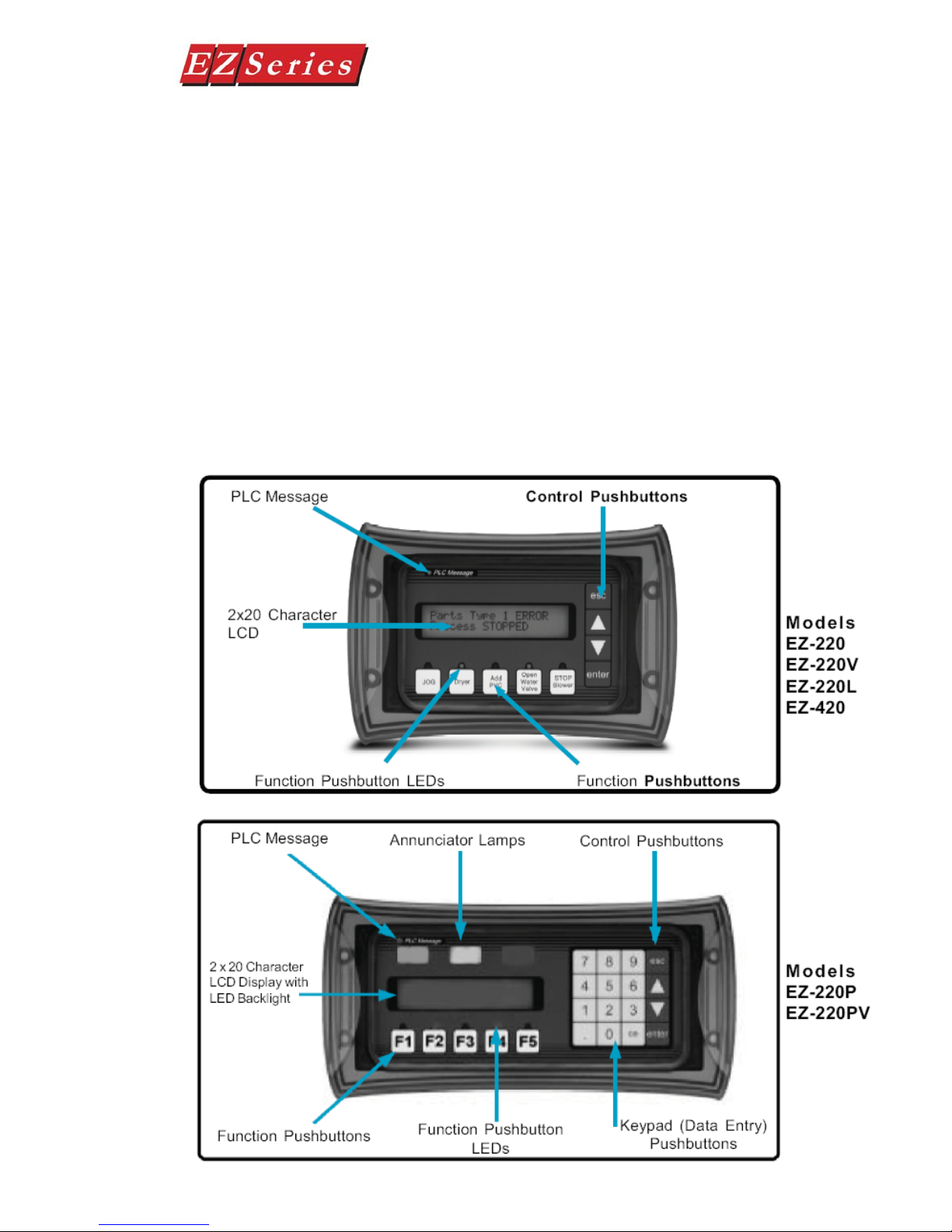
Front Panel Features
In this section, we will describe the front panel features of the EZSeries Set
Point Display Set Point Display Panel. Descriptions of the PLC Message LED,
Pushbuttons, Pushbutton LEDs, PLC Messages, and Local Messages are
provided. To understand the Features, see Chapter 3, Learning the Features.
For a demonstration of how to program the panel indicators and controls, please
refer to Chapter 4, Tutorial.
Operator Controls and Indicators
Each EZSeries Set Point Display Set Point Display Panel provides sealed
membrane Pushbuttons for operator interface with a PLC. Pushbuttons may
be used to begin events or tasks within the PLC, such as Start/Stop Control.
Pushbutton inputs are monitored for ON/OFF conditions in your PLC ladder logic
program. EZSeries Set Point Display Set Point Display Panel Pushbuttons are
Control Pushbuttons or Function Pushbuttons or Data Entry Keypad pushbuttons
available in two models (EZ-220P & EZ-220PV).
Text Panel Hardware Manual
10
EZ-TEXT-M-E
Text Panel Hardware Manual
INTRODUCTION
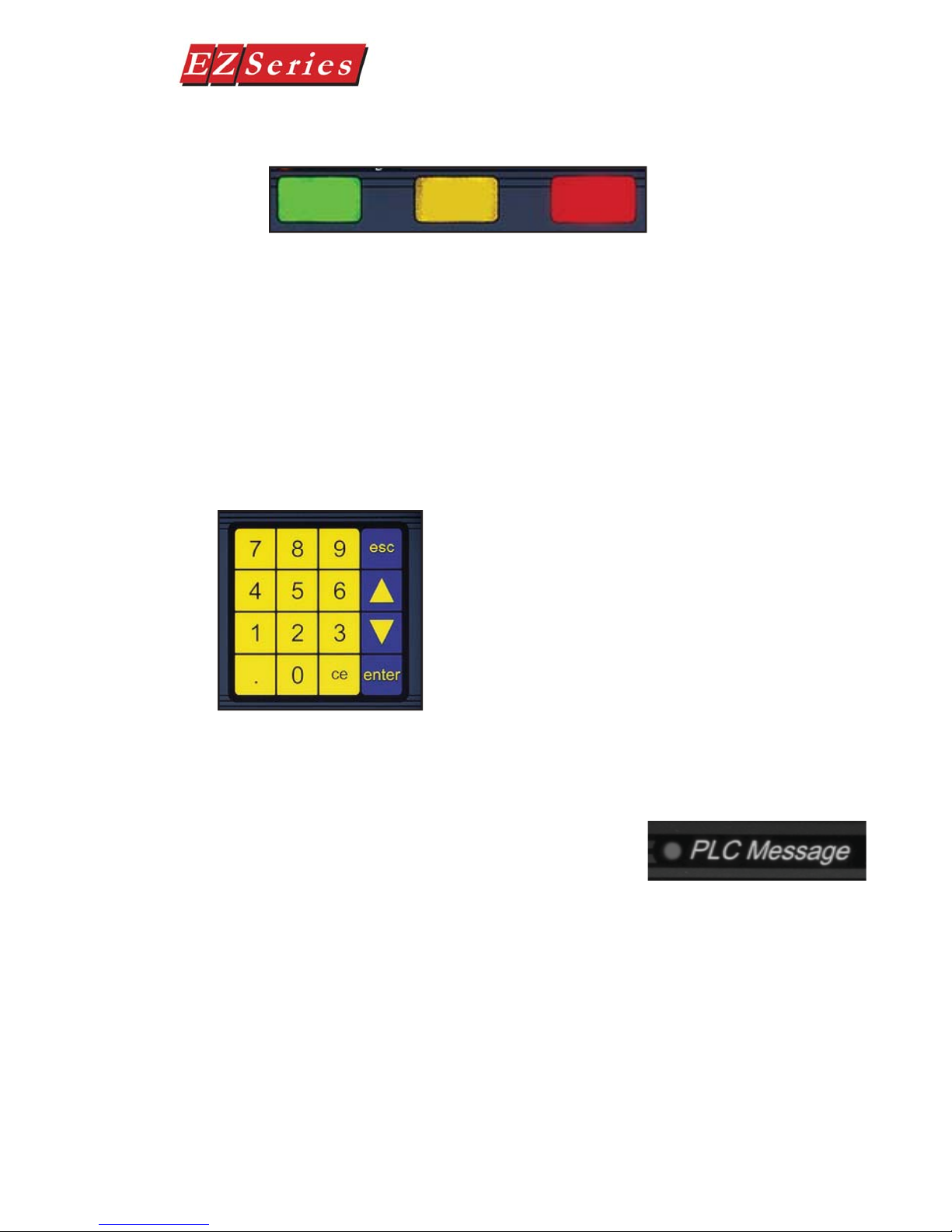
Annunciator Lamps
The EZ-220P & EZ-220PV models contain 3 tri-color Annunciator Lamps above
the LCD message window. Each of these lamps may be programmed to illuminate
in green, amber, or red and may be labeled to fi t your application. The lamps are
turned ON and OFF through your PLC ladder logic program. They are confi gured
with EZSeries Set Point Display Text Panel Programming Software and may be
confi gured to display status or the condition of any operation being controlled
within the PLC.
Data Entry (Keypad) Pushbuttons
The EZ-220P & EZ-220PV also feature a numeric keypad.
Use this keypad to enter or change embedded data values.
To update or enter a data value, the enter button must be
pressed to select the data value. Then you may use the
numeric keypad or the UP Arrow (increment) or DOWN
Arrow (decrement) to adjust the value. For the PLC to
acknowledge the change in value, you must press enter
again (sends the updated value to the PLC.) The CE
( Clear Entry) button is used to clear, or set back to zero,
the current value.
PLC Message LED
This LED will illuminate to indicate that the PLC
has triggered a message that will be displayed
in the LCD window. The pushbuttons are
disabled for 3 seconds after a PLC message
is displayed to ensure that the operator sees
the message. The LED will turn OFF when
the operator presses the escape pushbutton,
thereby acknowledging message received.
EZ-TEXT-M-E
11
Text Panel Hardware Manual
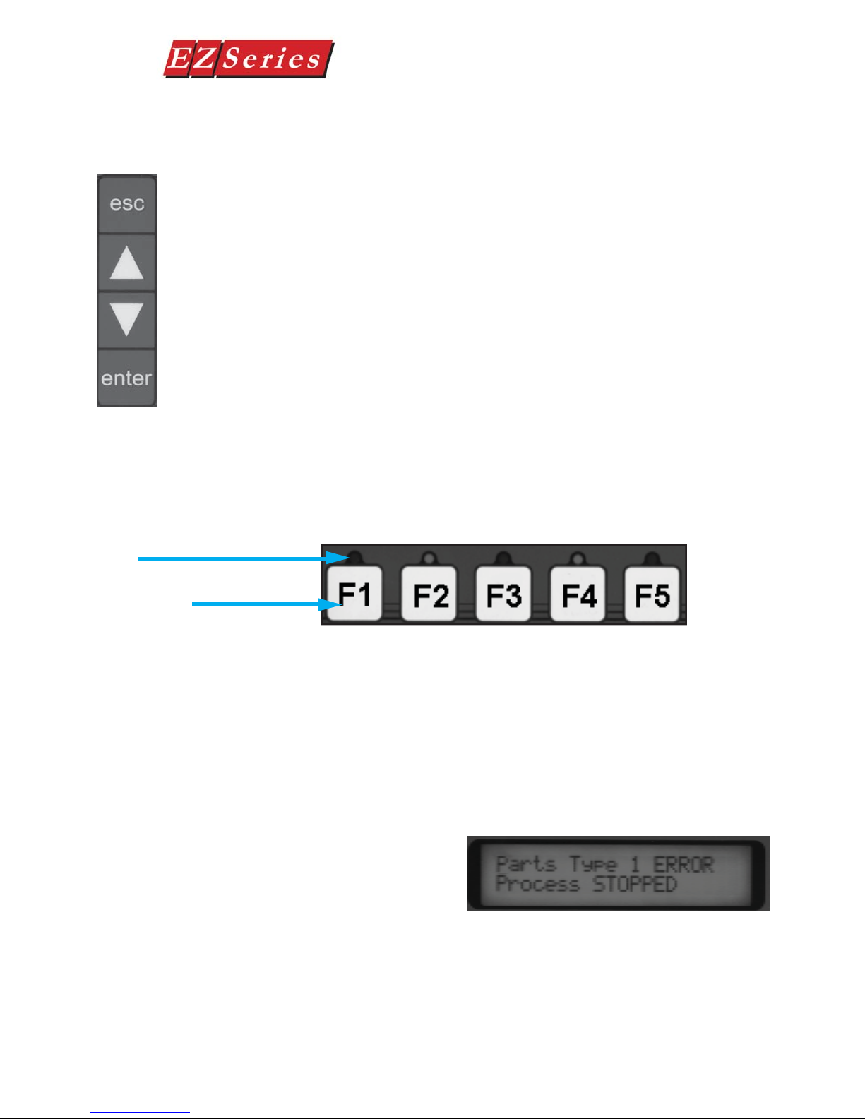
Control Pushbuttons
There are 4 Control Pushbuttons on the front panel. These buttons consist of
an esc ( escape), ( UP Arrow), ( DOWN Arrow), and enter pushbutton. The
arrow buttons are used to scroll through local messages or to change a value
within an interactive message. As the operator presses the buttons, the numeric
value will increment or decrement, respectively. As it is adjusted, the value
WILL NOT BE UPDATED in the PLC data register until the enter pushbutton is
pressed. When completed, the operator will press the enter pushbutton and the
value will be written to the PLC. Press esc to abort or cancel the adjustment
without writing the value to the PLC.
Function Pushbuttons
There are 5 Function Pushbuttons that are user-defi ned. They may be confi gured
as one of three “ switch” types; Alternate, Momentary, or Panel Set & PLC
Release (described on page 69.) They are confi gured as discrete input signals
to the PLC. These pushbuttons are labeled F1 through F5 or may be custom
labeled to suit their function or application.
LEDs
Function Pushbuttons
Pushbutton LEDs
There are LEDs located above each of the user-defi ned pushbuttons. These
LEDs can indicate if the pushbutton status condition is ON or OFF, or it can be
controlled independently by a PLC. You may choose the type of LED Control
while confi guring your panel (see Confi guration, Chapter 5). There are three
different controls— By Button, By Button & Flash, or By PLC, that will determine
LED response when the pushbuttons are pressed.
Character LCD Display with LED
Backlight
Messages display in the Character
LCD Display Window with LED
Backlight. The LCD window supports
two line by twenty characters (EZ220, EZ-220V , EZ-220PV , EZ-220P ,
& EZ-220L models), or four line by
twenty character (EZ-420 models)
messages.
12
EZ-TEXT-M-E

Text Panel Hardware Manual
INTRODUCTION
Messages
PLC Messages can be programmed to display PLC register values and allow
the operator to change a PLC register value. Up to 3 data variables can be
programmed to display in each message. The messages are entered using
EZSeries Set Point Display Set Point Display Panel Programming Software.
Up to 256 PLC Messages may be confi gured and stored in the EZSeries Set
Point Display Set Point Display Panel. PLC Messages are numbered 1 to 256.
The message control type may be static text, dynamic, or interactive. The PLC
logic program controls which messages are displayed. The PLC Message LED
illuminates when a PLC generated message is being displayed.
Local Messages are also displayed in the LCD Display Window. Local Messages
provide pertinent information or instructions to the operator and are displayed
in a menu hierarchy. They can also be programmed to display values from a
PLC register that the operator may change using the EZSeries Set Point Display
Set Point Display Panel control buttons. You may create Folders to group
messages pertaining to the same topic. Local Messages and Folders can be
grouped in up to 3 levels using the EZSeries Set Point Display Set Point Display
Panel Programming Software. The fi rst character in a Folder message display
is a “+” or “–” indicating folder status (closed or open). The next 19 characters
of the display are for the Folder text (Messages do not have a + or -, so all 20
characters can be used for text.) Local Messages allow the operator to select
and initiate user-defi ned interaction. See Chapter 3, Learning the Features, for
more information.
Rear Panel Indicators
EZ-TEXT-M-E
TXD LED
This LED will toggle “on” and “off” to signal activity
on the transmission line.
RXD LED
This LED will toggle “on” and “off” to signal activity
on the receive line.
13
Text Panel Hardware Manual
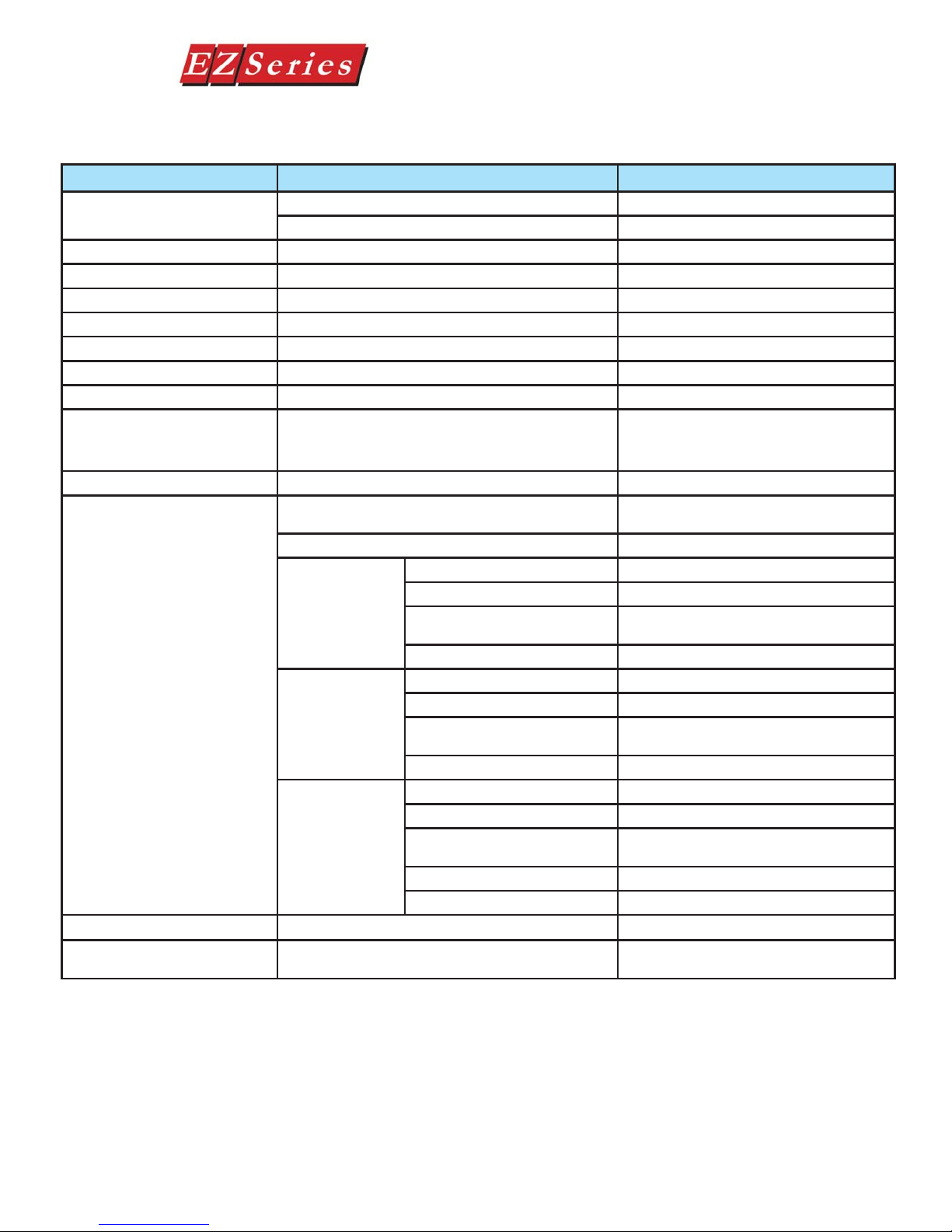
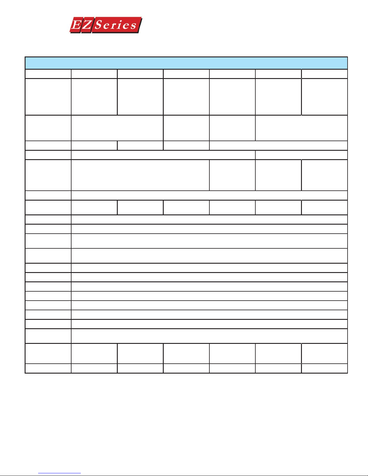
Specifi cations
EZSeries Set Point Display Set Point Display Panel Specifi cations
Part Number EZ-220 EZ-220L EZ-420 EZ-220P EZ-220V EZ-220PV
2x20 LCD display,
Description
Display Type
Character Height 5.55mm (0.22”) 8.06mm (0.316”) 4.75mm (0.187”) 5.55mm (0.22”)
Viewing Angle + or - 15 degrees horizontal + or - 60 degrees horizontal
Keypad Overlay Five user defi ned pushbuttons and four control pushbuttons
Service Power 24 VDC (20-30VDC operating range)
Power
Consumption
Enclosure NEMA 4, 4X (indoor)
Agency Approval UL, CUL, CE
Operating
Temperature
Storage
Temperature
Humidity 10 - 95% R.H., (non-condensing)
Electrical Noise NEMA ICS 2-230 showering arc ANSI C3790a-1974 SWC Level C Chattering Relay Test
Withstand Voltage 1000 VDC (1 minute) between power supply input terminal and protective ground (FG)
Vibration 5 - 55Hz 2 G for 2 hours in the X, Y, and Z axes
Shock 10 G for under 12 ms in the X, Y, and Z axes
Burn-in Temperature cycled 96 hours and then fully functional tested
LED/LCD Life 100,000 hours
Serial
Communications
Dimensions
Weight (lbs) .65 .85 .65 .85 .65 .85
fi ve user defi ned
pushbuttons, fi ve
LEDs
Character LCD, 2 lines by 20 characters
w/LED backlight
4 Watts @ 24 VDC
7.418 x 5.00
(188.419 x
126.9989)
2x20 LCD display,
large characters,
fi ve user defi ned
pushbuttons, fi ve
LEDs
4.5 Watts @ 24
VDC
Download/Program/PCS Port TS-232/RS422/RS485 15-pin D-sub (female)
10.018 x 5.00
(254.458 x
126.998)
4x20 LCD display,
fi ve user defi ned
pushbuttons, fi ve
LEDs
Character LCD,
4 lines by 20
characters w/LED
backlight
4 Watts @ 24 VDC
0 to 45 °C (32 to 113 °F)
-20 to 60 °C (-4 to 140 °F)
7.418 x 5.00
(188.419 x
126.9989)
2x20 LCD display,
numeric keypad,
fi ve user defi ned
pushbuttons, three
tri-color LED
annunciators
Character LCD,
2 lines by 20
characters w/LED
backlight
Numeric keypad,
fi ve user defi ned
pushbuttons and
four control push-
buttons
5.5 Watts @ 24
VDC
10.018 x 5.00
(254.458 x
126.998)
2x20 LCD display,
fi ve user defi ned
pushbuttons, fi ve
LEDs
Character VFD (Vacuum Fluorescent
Display), 2 lines by 20 characters w/LED
Five user defi ned
pushbuttons and
four control push-
buttons
6 Watts @ 24 VDC
7.418 x 5.00
(188.419 x
126.9989)
2x20 VFD display,
numeric keypad,
fi ve user defi ned
pushbuttons, three
tri-color LED
annunciators
backlight
Numeric keypad,
fi ve user defi ned
pushbuttons and
four control push-
buttons
8.5 Watts @ 24
VDC
10.018 x 5.00
(254.458 x
126.998)
14
EZ-TEXT-M-E

Hardware Installation
In this chapter....
— Custom Labels
— EMI Noise Filter Installation
— Mounting
— DIN Clip Mounting
— Connections and Wiring
2
Custom Labels
Text Panel Hardware Manual
Create Custom Labels
You may create custom labels for the EZSeries Set Point Display Text Panel
Function Pushbuttons that are particular to their function within your application. The labels slide into an existing slot in the panel overlay so that the text or
numbers you have printed will rest over the pushbuttons.
A Microsoft Word® document ( EZ-TEXT_INSERTS.doc) is installed in the
EZSeries Set Point Display Text Panel Program folder on your computer
when you installed your programming software. You must have Word
installed on your computer to open this document. This document will help
you create your labels. Two sheets of cover stock have also been shipped with
your panel.
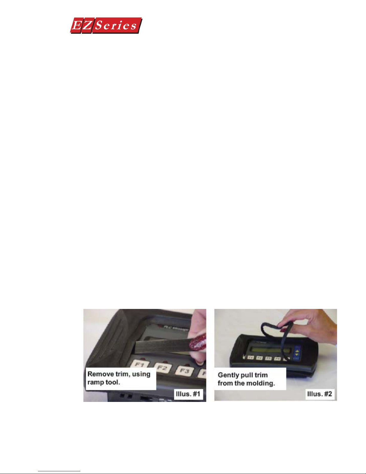
Install Custom Labels
A 1/2-inch x 4-inch fl at metal tool ( ramp tool) is shipped with each unit to
aid in the installation of the label inserts.
To install the pushbutton labels into the slots, perform the following steps.
1. Carefully remove rubber trim mold from panel front to access label
slots. (The trim has a barbed retaining rib that is pressed securely into
a channel in the front panel housing.) The ramp tool can be used to
help lift the trim (see illustration #1).
16
EZ-TEXT-M-E
Text Panel Hardware Manual
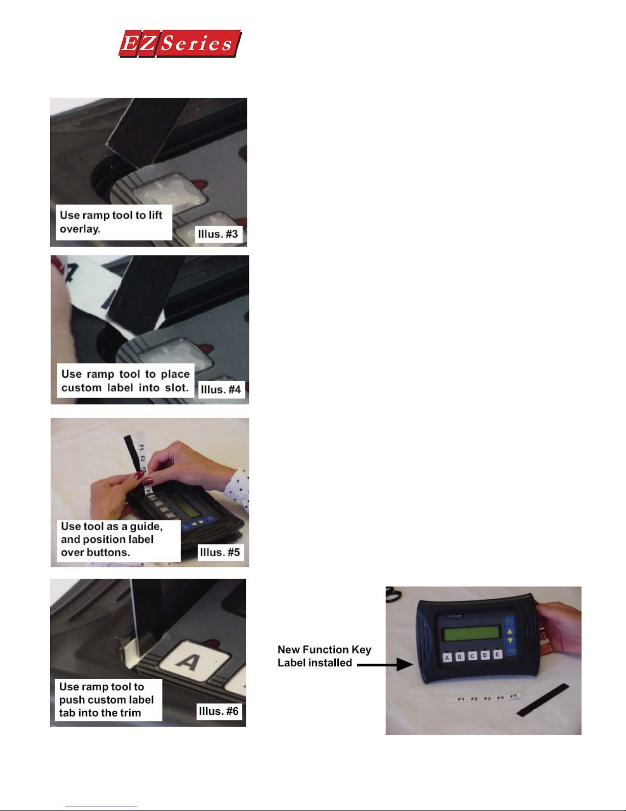
2. The recessed slot(s) where the labels are inserted
should now be visible.
3. Remove the factory installed label insert.
4. Use the corner of the ramp tool to lift the top layer of the
overlay (shown in illustration #3), just enough to
place the custom label into the slot. Hold the overlay
up with the ramp tool and start the custom label into
the slot (illustration #4).
5. Once the label has been placed into the slot, move the
ramp tool behind the label insert and use as a ramp to
guide the label insert into the slot until properly
positioned (illustration 5).
6. Push label tab down into trim channel with the ramp
tool (illustration 6).
7. Replace the rubber trim by fi rmly pressing the barbed
rib into the molded channel in the front panel housing.
EZ-TEXT-M-E
17
Text Panel Hardware Manual
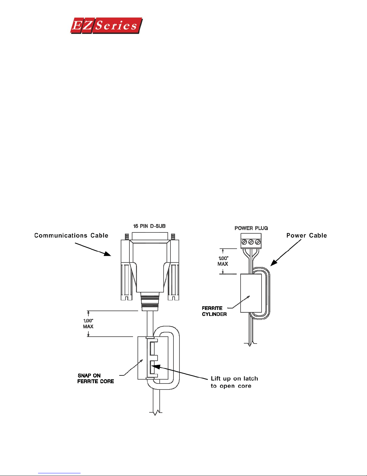
EMI Noise Filter Installation
EZSeries Set Point Display Text Panels are supplied with two ferrite cores that
should be attached to the cables prior to installation of the EZSeries Set Point
Display Text Panel. These cores are required to suppress EMI emissions that
are conducted through the Power Cable and the Communications Cable. The
fi gure, below, shows the ferrite cores properly installed. Attach the cores within
one inch of the EZSeries Set Point Display Text Panel connector. The cable
should be snugly wrapped once around the core, providing two passes through
the core.
The Power Cable Core is a solid ferrite cylinder . The Power Cable should pass
once through the core, be looped around and pass through a second time. Pull
the excess cable so that it rests snugly against the outside of the core.
The Communications Cable Core is a snap-together, split, ferrite core. This
core can be installed on a fi nished cable. Lift the latch to open the core. Wrap
the wire through the core center, snugly around the outside, and again through
the center. Close the core until the latch snaps. Ensure that the cable jacket is
not pinched between the two halves of the core. The fi nished cable should look
similar to the drawing shown below.
18
EZ-TEXT-M-E
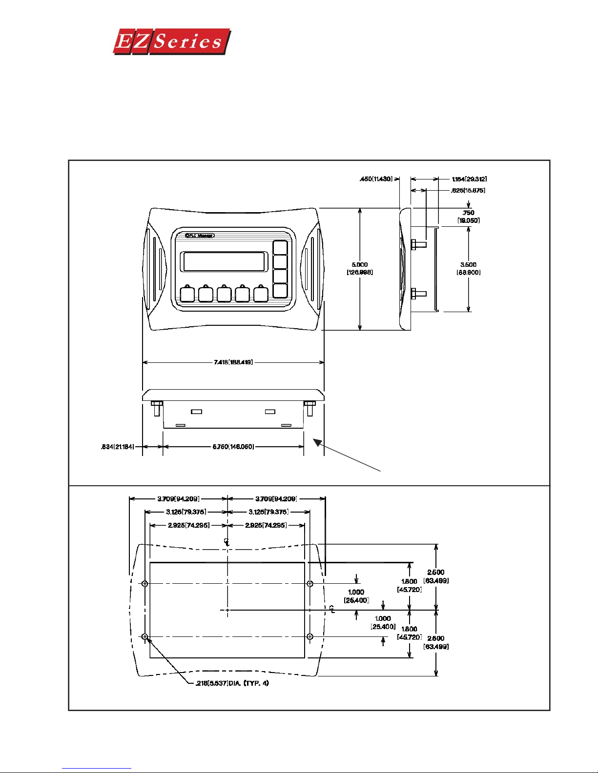
Mounting
Models EZ-220, 200V, & 420 Outline
Dimensions and Mounting Template
Text Panel Hardware Manual
EZSeries Set Point Display Text Panels can be mounted in two different ways:
Stud Mounting and DIN Clip Mounting. The panel comes with all the necessary
mounting hardware required for stud mounting. DIN Clips (P/N EZP-BRK-2) must
be ordered separately.
STUD Mounting:
Use the 4 studs and 4 nuts
with captive washers to secure the unit to the mounting surface. Requires a
5/16” wrench.
Mounting Studs (4 total)
EZ-TEXT-M-E
Mounting Template
19
Text Panel Hardware Manual
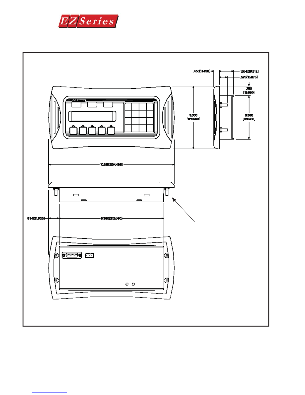
Model EZ-220P/EZ-220PV
Outline Dimensions
STUD Mounting:
Use the 4 studs and 4 nuts
with captive washers to
secure the unit to the mounting surface. Requires a 5/16”
wrench.
Mounting Studs (4 total)
20
EZ-TEXT-M-E
Text Panel Hardware Manual
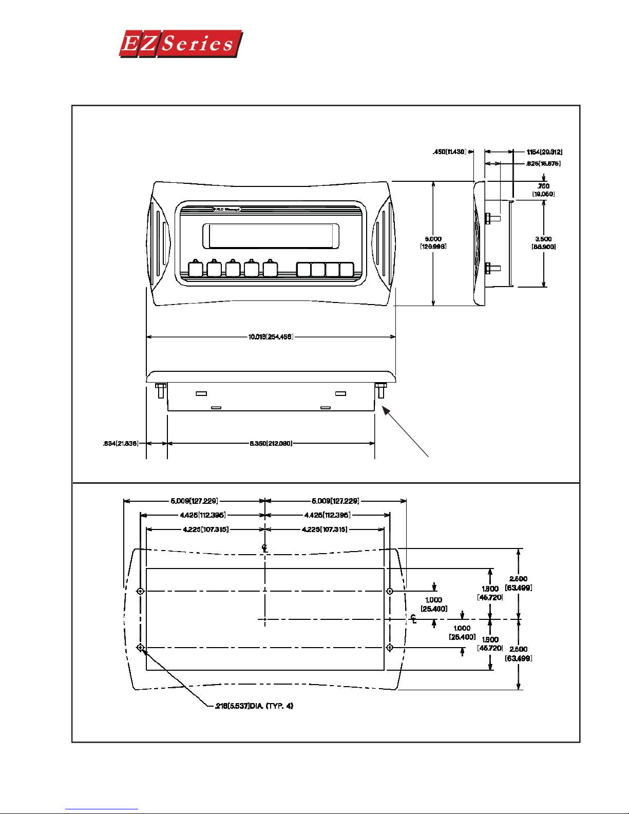
Model EZ-220L Outline
Dimensions and Mounting Template
STUD Mounting:
Use the 4 studs and 4 nuts
with captive washers to secure the unit to the mounting surface. Requires a
5/16” wrench.
Mounting Studs (4 total)
EZ-TEXT-M-E
Mounting Template
21

DIN CLIP Mounting
DIN Clips (P/N EZ-BRK-2) are metal brackets that attach to the panel and secure
the front bezel to a mounting surface with a screw. They provide an alternative
to bolting the panel into the mounting surface. There are 4 square holes in the
chassis (two on the top and two on the bottom). Insert the clip fl ange into this
hole and secure the EZSeries Set Point Display T ext Panel by tightening the DIN
CLIP screw until the front bezel is fi rmly pressed to the mounting surface.
Text Panel Hardware Manual
22
EZ-TEXT-M-E
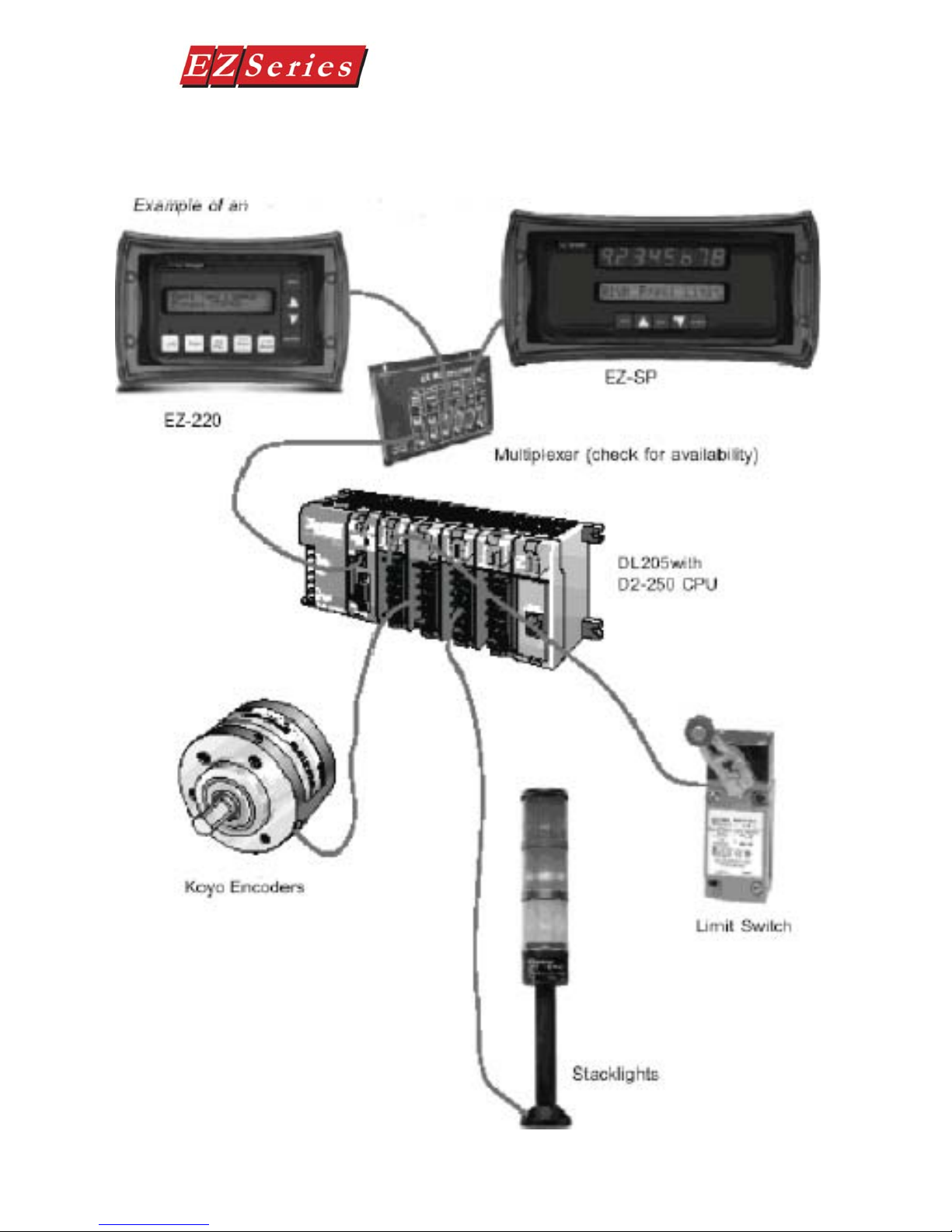
Connections and Wiring
EZSeries Text Panel Application
Text Panel Hardware Manual
EZ-TEXT-M-E
23
Text Panel Hardware Manual
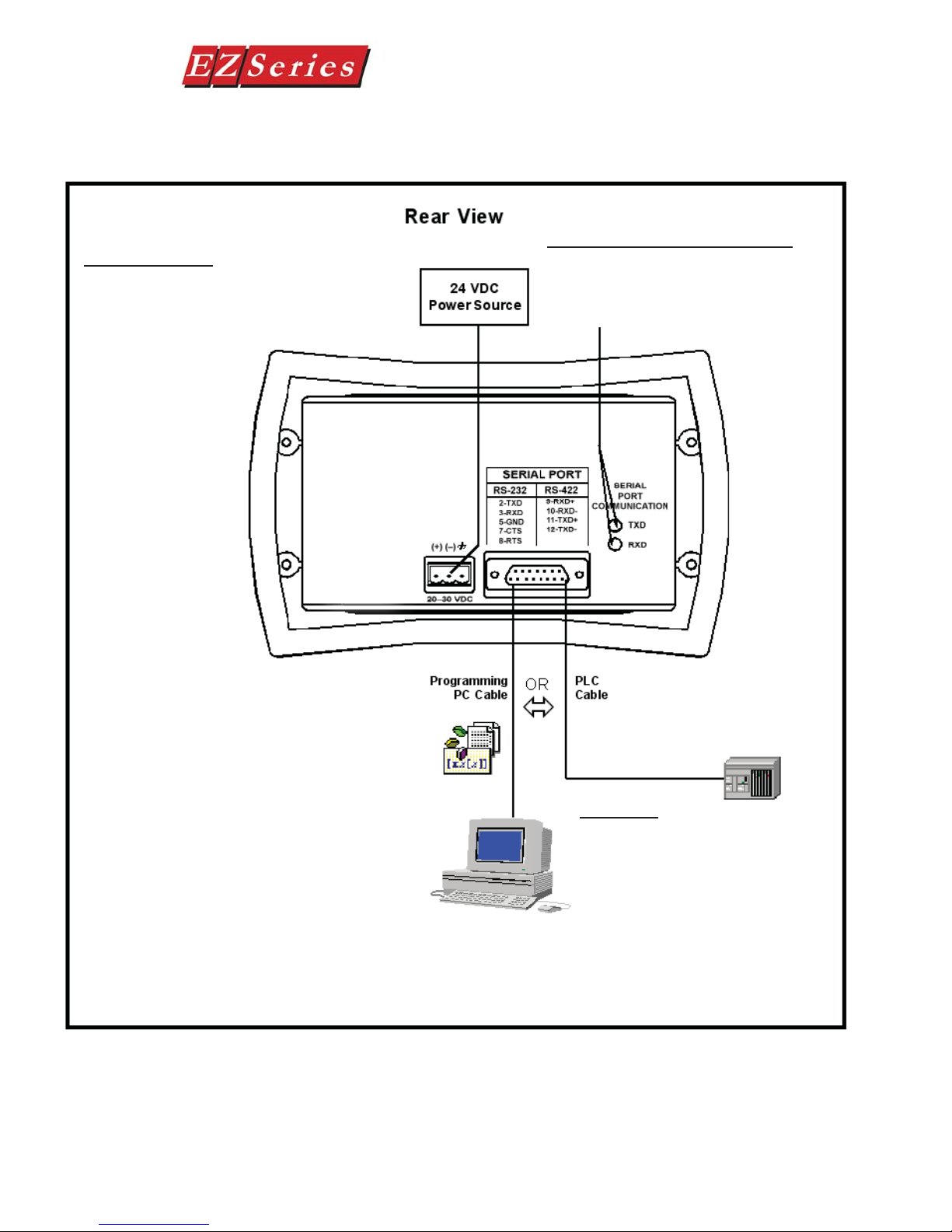
EZ-220, EZ-220V & EZ-420 Connections and Wiring
Power Connector
Block style connector is used to connect an
external 24VDC power supply . See Power Connector Pinout on page 27.
Serial Port Communication LEDs
These LEDs illuminate to show whether
the unit is sending or receiving data. See
page 91.
24
Serial Port
This port may be used to connect the
programming computer or a PLC (see
page 27). Use programming cable P/N
EZTEXT-PGMCBL to connect the PC. See
PLC Cable Part Number table, page 9 for
the appropriate PLC cable used by your
application. Block style connector is used
to connect an external 24VDC power
supply. See Power Connector Pinout
on page 27.
EZ-TEXT-M-E
Text Panel Hardware Manual
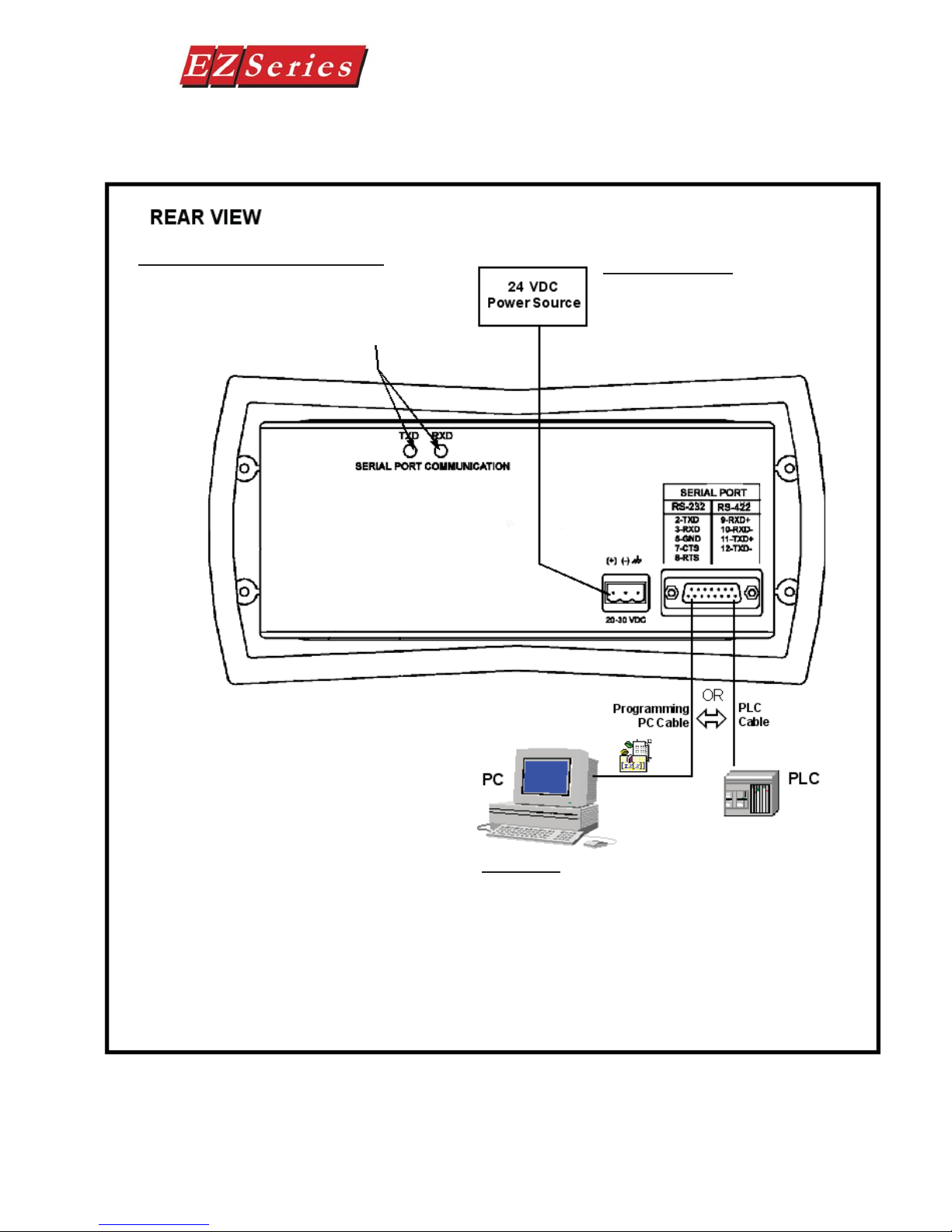
EZ-220P & EZ-220PV Connections and Wiring
Serial Port Communication LEDs
These LEDs illuminate to show whether
the unit is sending or receiving data. See
page 91.
Power Connector
Block style connector is used to
connect an external 24VDC power
supply . See Power Connector Pinout
on page 27.
EZ-TEXT-M-E
Serial Port
This port may be used to connect the programming
computer or a PLC (see page 27). Use programming cable
P/N EZTEXT-PGMCBL to connect the PC. See PLC Cable
Part Number table, page 9 for the appropriate PLC cable
used by your application. Block style connector is used
to connect an external 24VDC power supply. See Power
Connector Pinout on page 27.
25
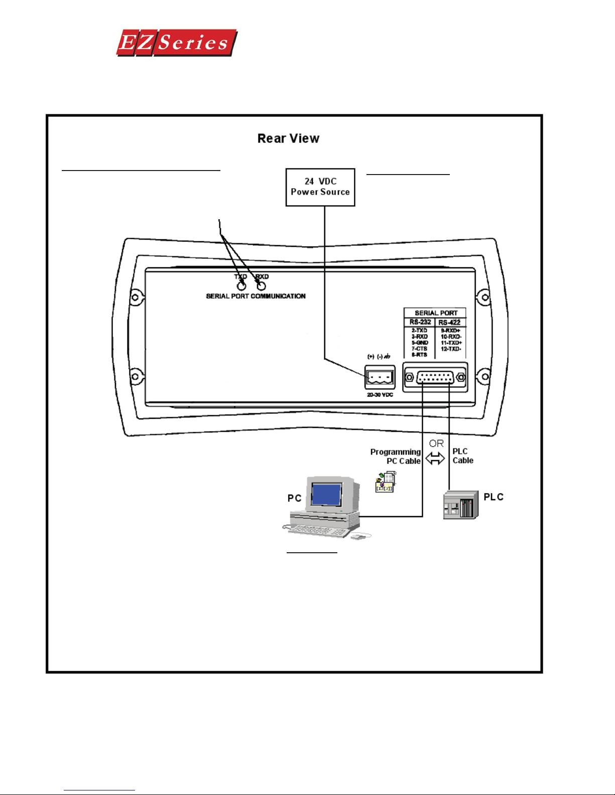
EZ-220L Connections and Wiring
Text Panel Hardware Manual
Serial Port Communication LEDs
These LEDs illuminate to show whether
the unit is sending or receiving data. See
page 91.
Power Connector
Block style connector is used to
connect an external 24VDC power
supply . See Power Connector Pinout
on page 27.
26
Serial Port
This port may be used to connect the programming computer or a PLC (see page 27). Use programming cable P/N
EZTEXT-PGMCBL to connect the PC. See PLC Cable Part
Number table, page 9 for the appropriate PLC cable used by
your application. Block style connector is used to connect an
external 24VDC power supply. See Power Connector Pinout
on page 27.
EZ-TEXT-M-E
 Loading...