

Ez DS-1150, DS-1100, DS-1250 User Manual

Digital Oscilloscope
Digital Oscilloscope

DECLARATION OF CONFORMITY
Manufacture's name : EZ Digital Co., Ltd
Manufacture's Address : 222-28, Nae-dong, Ojeong-gu,
Bucheon-si, Gyeonggi-do
R.O.KOREA, 421-160
Declares that the product :
Product name : Oscilloscope
Model number : DS - 1XXX ( X : 0 ~ 9 )
Date : December, 01, 2001
Conforms to the following product specifications:
Safety : EN 61010-1 : 1993 + A2 : 1995
(IEC 10101 : 1990 + A1 : 1992
+ A2 : 1995, Modified)
EMC : EN 61326/1997 + A1:1998
Supplementary information:
The product herewith complies with the requirements of the
Low Voltage Directive 73/23/EEC and the EMC Directive 89/336/EEC
Bucheon, Gyeonggi
Cheol Young Kim
Location
Quality Assurance Manager
2

WARRANTY
This instrument is warranted against defects in workmanship and materials. If any
failure, resulting from a defect in either workmanship or material should occur under
normal use within a year from the original date of purchase, such failure will be
corrected free of charge to the purchaser by repair or replacement of the defective
part or parts. When the failure is a result of user's neglect, natural disaster or accident,
we charge for repairs regardless of the warranty period.
This warranty is subject to the following conditions and limitations.
The warranty is void and inapplicable if the defective product is not brought or sent
prepaid to our authorized service center or sales outlet within a warranty period.
Defective product is, on EZ Digital Co., Ltd.'s sole judgement, indemnified at a
purchased price, replaced with new one or repaired without charge or with charge.
In the event warranty service is needed, purchaser should get in touch with the service
center or sales outlet, or properly pack and return the product to the service center
or sales outlet at his or her own expense. A returned product must be accompanied
by a written description of the defect. We return the product to the purchaser at his or her
own expense.
In case the warranty does not cover the product on EZ Digital Co., Ltd.'s
sole judgement, we repair the product after obtaining prior permission from the
purchaser who received pro forma statement about repairing charges. In such a
case, EZ Digital Co., Ltd. bears the transportation expenses required to send back all the
repaired products temporarily, and then repair and transportation expenses will be
charged against the purchaser by the statement of accounts.
When the authorized sales agents sell our product, they must notify the purchaser of the
warranty contents, but have no right to stretch the meaning of original warranty contents
or offer additional warranty. EZ Digital Co., Ltd. does not provide any other promise or
suggestive warranty and holds no liability for the damage caused by negligence,
abnormal use or natural disaster. EZ Digital Co., Ltd. is not responsible for damages
though it was notified about the danger in advance.
For more information on service or overall repairs and maintenance of old and decrepit
products, be sure to contact our service center or sales outlet.
3

PRODUCT CONTENTS
OSCILLOSCOPE
- Set 1 set
SUPPLIED ACCESSORIES
- Operation manual
- Power cord
- 100MHz probes x1/x10 2EA (Only DS-1100)
OPTIONAL ACCESSORIES
- RS-232C thermal printer (Printy2 with RS-232C Cable)
- Test probes
150MHz probes x1/x10
250MHz probes x1/x10
- Service manual
- PC Software kit(RS-232C Cable, USB Cable, PC interface Program)
- Interface Card Type A (RS-232C, Centronics, USB)
- Interface Card Type B (RS-232C, Centronics)
4

CONTENTS
1. INTRODUCTION
1-1 KEY FEATURES
1-2 NOTES FOR A SAFETY OPERATION
1-2-1 OPERATING ENVIRONMENT
1-2-2 SAFETY SYMBOLS
1-2-3 POWER SOURCE-RELATED WARNINGS
1-2-4 PLACE-RELATED WARNINGS
1-2-5 OPERATION-RELATED WARNINGS
1-2-6 SERVICE-RELATED WARNINGS
1-2-7 CLEANING AND MAINTENANCE
1-3 NOTES TO USERS
1-3-1 NOTICE FOR PROPER MEASUREMENT
1-3-2 WHEN CONNECTING PERIPHERAL DEVICES
1-3-3 PROBE
1-4 INSTALLATION
1-4-1 POWER CODE
........................................................................................... 18
..................................................................................... 20
...................................................................................7
......................................................................................8
..............................................9
..........................................................9
.........................................................................9
....................................10
......................................................10
.............................................11
..................................................12
.................................................13
................................................................................14
.....................................14
................................................................................ 20
.......................... 15
1-4-2 INTERFACE CARD
2. DESCRIPTION
.................................................................................... 22
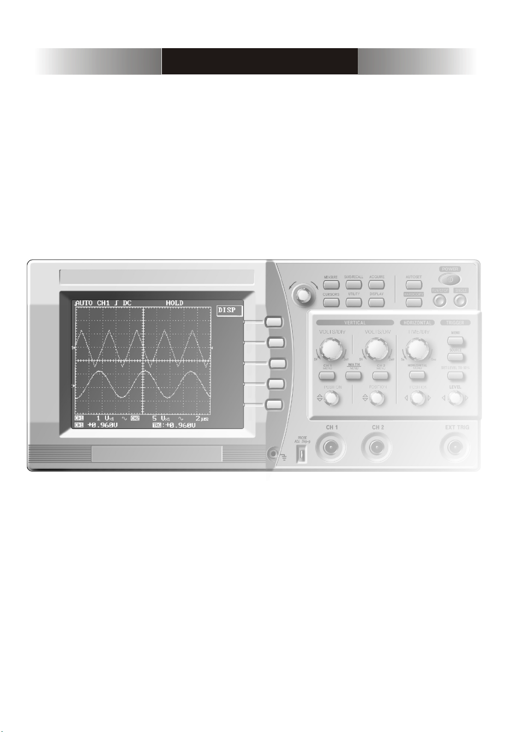
2-1 KEY & DISPLAY DESCRIPTION
2-1-1 DISPLAY OVERVIEW
2-1-2 VERTICAL AXIS OPERATION
2-1-3 HORIZONTAL AXIS OPERATION
2-1-4 TRIGGER
2-1-5 MENUS
2-1-6 CONNECTORS
2-1-7 THE MENU BOX BUTTON AND FUNCTION KNOB
2-2 MENUS
2-2-1 AUTOSET
2-2-2 VERTICAL
2-2-3 MATH
2-2-4 HORIZONTAL
2-2-5 TRIGGER
........................................................................................ 27
........................................................................................... 28
.............................................................................. 29
.................................................................................................... 30
.......................................................................................30
......................................................................................31
............................................................................................. 33
............................................................................... 37
....................................................................................... 38
.......................................................................... 20
..................................................... 23
.................................................................... 23
...................................................... 25
................................................. 26
..................... 29
5

2-2-6 MEASURE
..................................................................................... 43
2-2-7 SAVE/RECALL
2-2-8 ACQUIRE
2-2-9 CURSORS
2-2-10 UTILITY
2-2-11 DISPLAY
2-2-12 HARDCOPY
2-3 USING THE FUNCTIONS EFFECTIVELY
2-3-1 USING THE ZOOM FUNCTION
2-3-2 USING THE SINGLE FUNCTION
2-3-3 USING FFT (FAST FOURIER TRANSFORMATION)
........................................................................................ 51
3. APPENDIX
3-1 SPECIFICATIONS
3-2 FACTORY DEFAULTS
.............................................................................. 45
....................................................................................... 47
..................................................................................... 49
...................................................................................... 53
................................................................................. 55
...................................... 56
.................................................... 56
.................................................. 57
............................................................................................. 60
................................................................................ 61
........................................................................ 65
.................... 58
6
1. INTRODUCTION
7

1-1 KEY FEATURES
The 16bit high speed microprocessor adoption enables the scope to acquire
a typical 100,000 points per second and quickly update the picture on
the screen.
Basic memory length of DS-1150 is 10kB and that of DS-1150 & DS-1250 is 32kB.
Captured waveforms can be zoomed in and analyzed in detail. Also its built-in
10ns peak detection circuit enables it to capture high frequency noise even at
a low speed time/div and magnify and analyze it using the zoom-in function.
In addition, it can save up to 10 waveforms and provide diversified analysis
function like FFT which is available on high priced products.
General Features
- 100MHz bandwidth(DS-1100), 2 CH dual digitizer
- 150MHz bandwidth(DS-1150), 2 CH dual digitizer
- 250MHz bandwidth(DS-1250), 2 CH dual digitizer
- 100MS/s simultaneous maximum sampling rate per channel,
200MS/s sampling rate for one channel only
25GS/s equivalent sampling rate per channel
- 10ns peak detection for glitch capture even in ROLL mode
- Max. 400Vpk input voltage into all channels
Convenient Functions
- Direct single trigger capture function using a hot-key
- Simultaneous 5 waveform informations auto measurement and FFT analysis
- Auto trigger level setting to 50%
- Saving 10 waveforms & 10 setup parameters
- Convenient inserting interface card for RS-232C, hardcopy and USB
8
1-2 NOTES FOR A SAFETY OPERATION
1-2-1 OPERATING ENVIRONMENT
This instrument will operate to its specifications if the environment is
maintained within the following conditions.
- Indoor use
- Altitude up to 2000m use
- Operating temperature 0 ~ 40
- Relative humidity 80%
- Main supply voltage fluctuations not exceed 10% of the nominal voltage.
- After turning on the instrument, please allow a pre-heating period of as long
as some 15 minutes.
This instrument has been qualified to the following EN61010-1 Category :
- Installation (Over-voltage) category 2
- Pollution Degree 2
1-2-2 SAFETY SYMBOLS
Where these symbols or indications appear on the instrument or in this
manual, they have the following meanings.
Refer to accompanying documents for Safety-related information.
Wherever the symbol is present, see "NOTES FOR A SAFETY OPERATION"
part in this manual.
Ground
Risk of hazard which may cause injury to human body or danger to life.
If a WARNING appears on the instrument , and in this manual, do not
proceed until its suitable conditions are understood and met.
Risk of hazard which causes fire or serious damage to the instrument or
other equipment. Do not proceed until its suitable conditions are met.
9
1-2-3 POWER SOURCE-RELATED WARNINGS
Protection of Power Cord and Unplugging
Power-supply cords should be routed so that they are not likely to be waked
on or pinched by items placed upon or against them, paying particular
attention to cords at plugs, convenience receptacles, and the point where
they exit from the instrument. For added protection for this instrument during
a lightening storm, when it is left unattended and unused for long periods
of time, unplug it from the power source. This will prevent damage to the
instrument due to lightening and power-line surges.
Overloading
Do not OVERLOAD power source and extension cords as this can result in a risk
of fire or electric shock.
1-2-4 PLACE-RELATED WARNINGS
Object and Liquid Entry
Never push objects of any kind into this instrument through openings as they
may touch dangerous voltage points or short out parts that could result in a
fire or electric shock. Never spill liquid of any kind on the instrument. Do not
use this instrument near water- for example, near a bath tub wash bowl,
kitchen sink, or laundry tub, in a wet basement, or near a swimming pool, and
the like. Keep the instrument away from damp air, water and dust.
Unexpected trouble may be caused when the instrument is placed in a damp
or dusty place.
FLAMMABLE AND EXPLOSIVE SUBSTANCE
Avoid using this instrument where there are gases, and where there are
flammable and explosive substances in the immediate vicinity.
Unstable Location
Do not place this instrument on an unstable cart, stand, tripod, bracket, or
table. The instrument may fall, causing serious injury to a person, and serous
damage to the instrument. Do not place or use the instrument in a place
subject to ventilation.
10

1-2-5 OPERATION-RELATED WARNINGS
Power Switch
Before plugging the power cord in be sure to check that the power switch is
set to off for protection of the instrument.
Ground Connection
When connecting a probe , connect the ground side of the probe to the ground
of the signal source. At a floating status, a potential might be produced with
respect to other devices or ground, resulting in damaging the instrument,
probe, other measuring instruments, etc.
CH 1
GND
Excessive Input Voltage
In order to avoid electric shock or fire, the input voltages to the probes, BNC
connectors are specified as follows. Do not apply higher voltages. Before using
probe, check the rated voltage with the naked eye. Remove the unused probe
not to contact with ambient high voltage parts. If you apply a higher voltage
more than 400Vpk , remove the probe out of BNC terminals to ensure against
accidental danger
Maximum input Voltage
- CH1, CH2 all 400Vpk
Do not Use Non-certified Probes
Use the probes certified according to EN 61010-1 and EN 61010-2-031 in europe.
Use the UL listed probes in america.
11
1-2-6 SERVICE-RELATED WARNINGS
Damage Requiring Service
Do not attempt to service this instrument yourself as opening or removing
covers may expose you to dangerous voltage or other hazards.
Unplug this instrument from the power source and after servicing to
qualified service personal under the following conditions
- When the AC power cord or plug is damaged.
- When the LCD is damaged, you must not open the cover during operation.
There is a risk of electric shock.
- If liquid has been spilled, or objects have fallen into the instrument.
- If the instrument does not operate normally by following the operating
instructions. Adjust only those controls that are covered by the operating
instructions as an improper adjustment of other controls may result in
damage and will open require extensive work by a qualified technician to
restore the instrument to instrument to its normal operation.
Unplug the power cord from the power source before opening the cover, and
then remove the probe. Even if the instrument is disconnected from all the
power sources, special attention is required in service as the inside capacity
might be in charged condition. When replacement of fuses or other parts is
required, be sure the service technician has used replacements parts specified
by the manufacturer or have the same characteristics as the original part.
Unauthorized substitutions may result in fire, electric shock or other hazards.
There is a risk of electric shock. No user
serviceable parts inside. Leave repair to
qualified personnel.
Safety Check
Upon completion of any service or repairs to this instrument, ask the service
technician to perform safety checks to determine that the instrument is proper
operating condition.
12
1-2-7 CLEANING AND MAINTENANCE
Maintenance routines performable by the operator are listed in this section.
More advanced routines (i.e., procedures involving repairs or adjustments
within the instrument) should be referred to service personnel.
Cleaning
If the outside of the case becomes dirty or stained, carefully wipe the surface
with a cloth moistened with detergent, then wipe the cleaned surface with a
dry cloth. In case of severe stain, try cleaning with a cloth moistened with
alcohol. Do not use powerful hydrocarbons such as benzene or paint thinner.
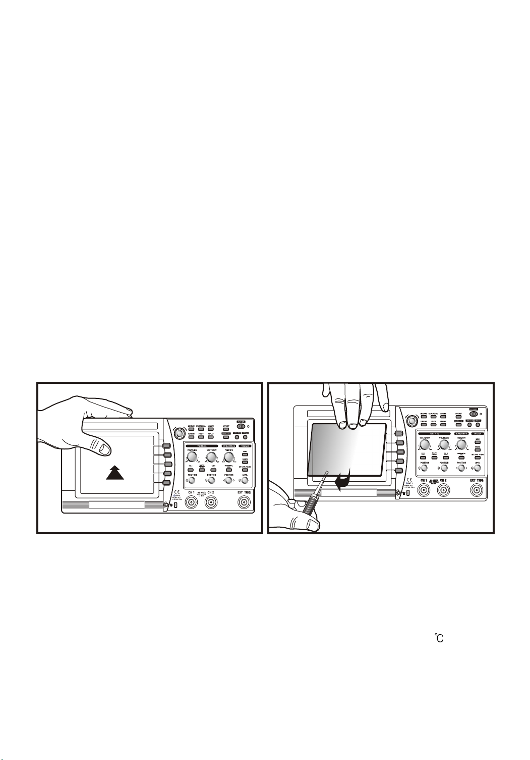
Dust and/or smudges can be removed from the LCD screen. First remove the
front case and filter. Clean the filter (and the LCD face, if necessary) by wiping
carefully with a soft cloth or commercial wiping tissue moistened with a mild
cleaning agent. Take care not to scratch them. Do not use abrasive cleanser
or strong solvents. Let the cleaned parts dry thoroughly before reinstalling
the filter and front case. If it is installed wet, dew may form and blur the
waveforms. Be particularly careful not to get fingerprints on the filter or LCD
face.
MENU
MENU
Maintenance
This instrument should never be placed in a built-in installation such as a
bookcase or rack unless proper ventilation is provided. Ideal ambient
temperature and relative humidity for storing the instrument are 23 and 60%
13

1-3 NOTES TO USERS
1-3-1 NOTICE FOR PROPER MEASUREMENT
It is recommended to allow about 15 minutes after power on as warm up time
before starting measurement. Traces may drift a little just after power on.
When measuring a signal with high accuracy trace declination, you can correct
the trace position using the automatic calibration function.
Before starting up this function, allow enough warm-up time.
The calibration is classified into software calibration for resorting to the
automatic calibration function in the menu, and hardware calibration for
optimizing the internal circuitry in a wide range.
1. The software calibration is recommended when the ambient temperature
has excessively changed (5 ) or when 1000 operating hours or 6 months
has been attained. If the trace is displayed excessively or when it is desired
to optimize the measurement, execute it referring to the automatic
calibration. Before calibration, disconnect all inputs for accurate adjustment.
2. The hardware calibration is necessary to keep the instrument to a stable
operation status. It is recommended to adjust the instrument every 2,000
operating hours or every year.
SOFTWARE CALIBRATION FOR OPTIMUM MEASUREMENT
The changes in measurement accuracy due to use environments
(temperature, humidity, etc) can be optimally corrected automatically
by activating the calibration. It is recommended to perform calibration
when any of the following cases applies.
- Before a customer starts to use this instrument first
- When an ambient temperature changes more than 5 , compared
with that at the time of the previous calibration.
- Every 6 months or 1000 operating hours
- Optimization of measurement accuracy is required
14
1-3-2 WHEN CONNECTING PERIPHERAL DEVICES
When connecting a printer and a personal computer to the oscilloscope, be
sure that the oscilloscope, the printer and the personal computer are all off,
and then connect them. Pay attention to the direction of the cables and the
ports of the peripheral devices. Before operation, be sure to carry out the
setting necessary for the printer and the personal computer. (For the setting
of the printer and the personal computer, refer to the operation manual for
each) If you operate the printer and the personal computer which are
improperly set, abnormal operation will occur. In this case, turn off the
instrument, the printer and the personal computer at once, and set them
properly again and operate them.
Before using peripheral devices, Interface card should be installed in this instrument.
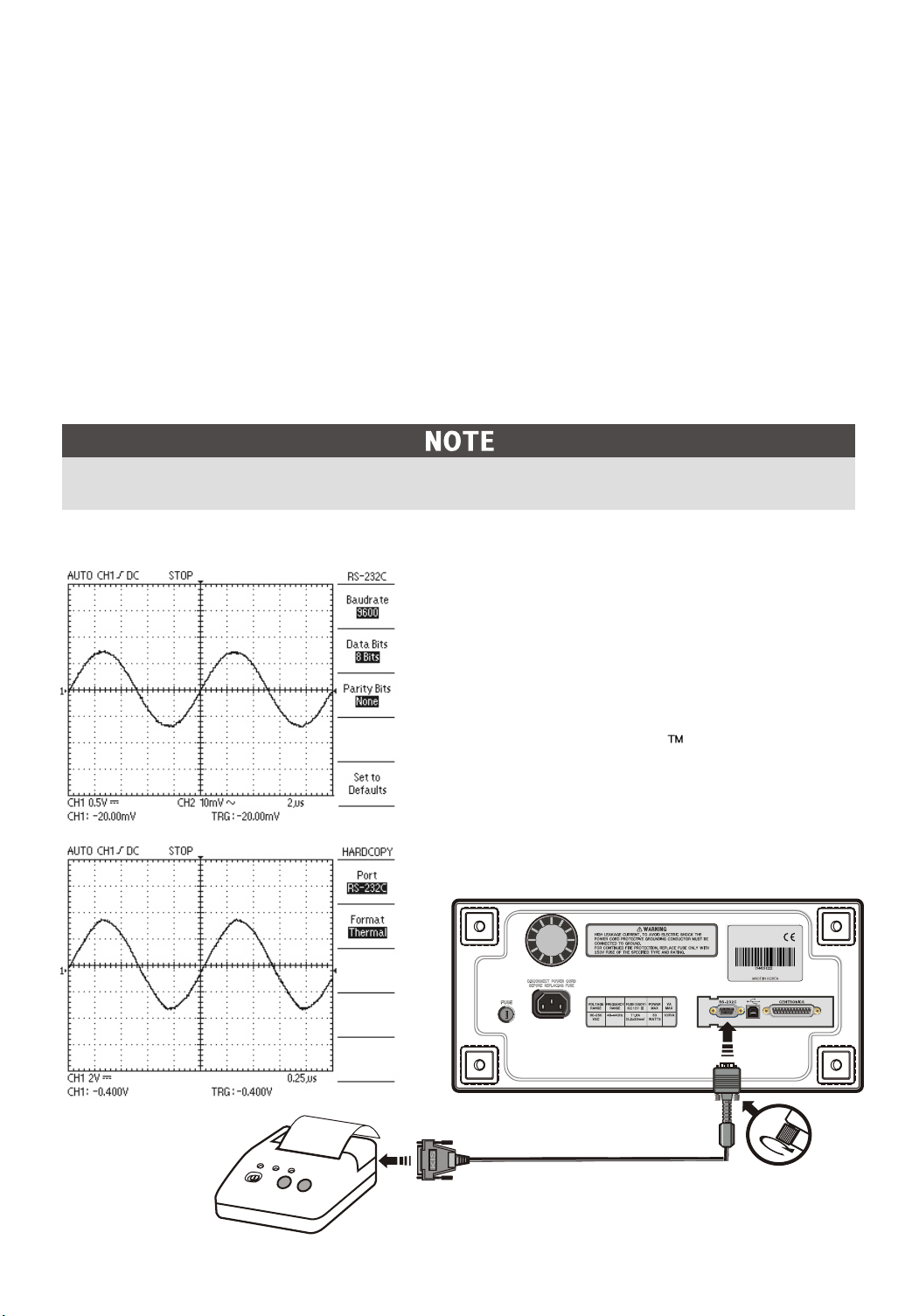
When using thermal printer opertion, RS-232C settings are as follows
- BAUD RATE : 9600 bps
- PARITY BIT : None
- DATA BIT : 8 bit
* RS-232C Serial cable is 9pin
(male) to 25pin(male) null cable.
* RS-232C thermal printer is
Printy 2 of SANEI Electric INC
15
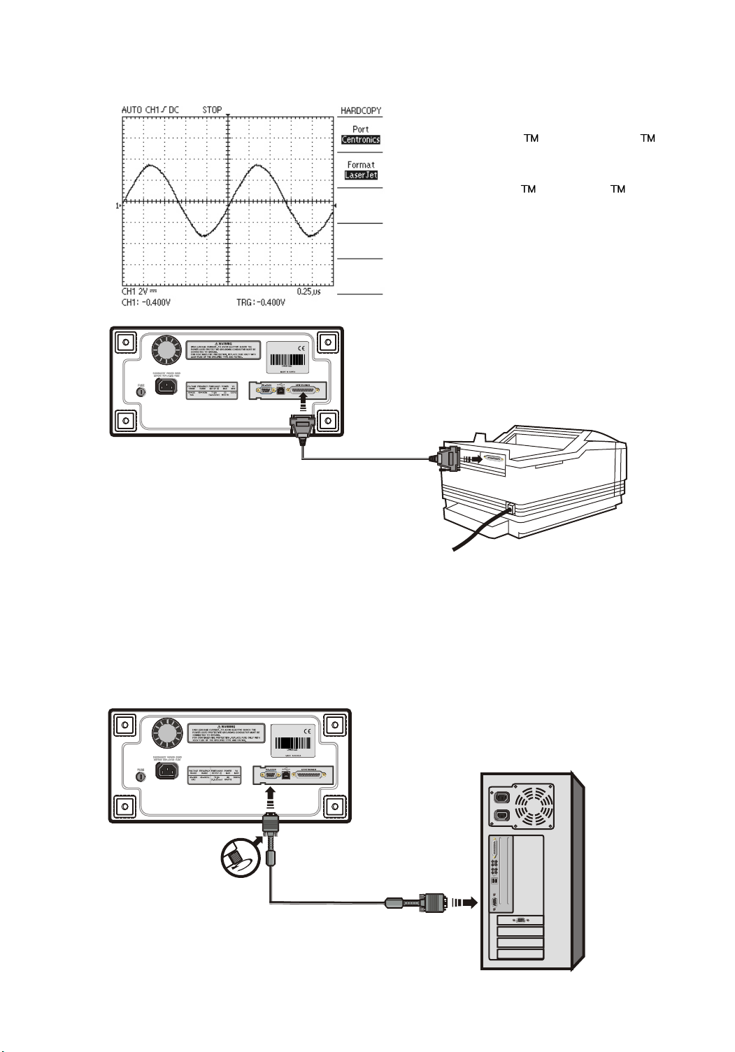
When using printer operation, Centronics settings are as follows
* This instrument supports
DeskJet and LaserJet with
PCL level 3
* DeskJet , LaserJet is
registered trade mark of HP.
K.I.S
When using PC communication operation, RS-232C settings are as
follows
Before communicating with a PC, the PC software kit(option) should be
installed in your PC. If you want to have more detailed information, refer to the
PC software kit manual.
16
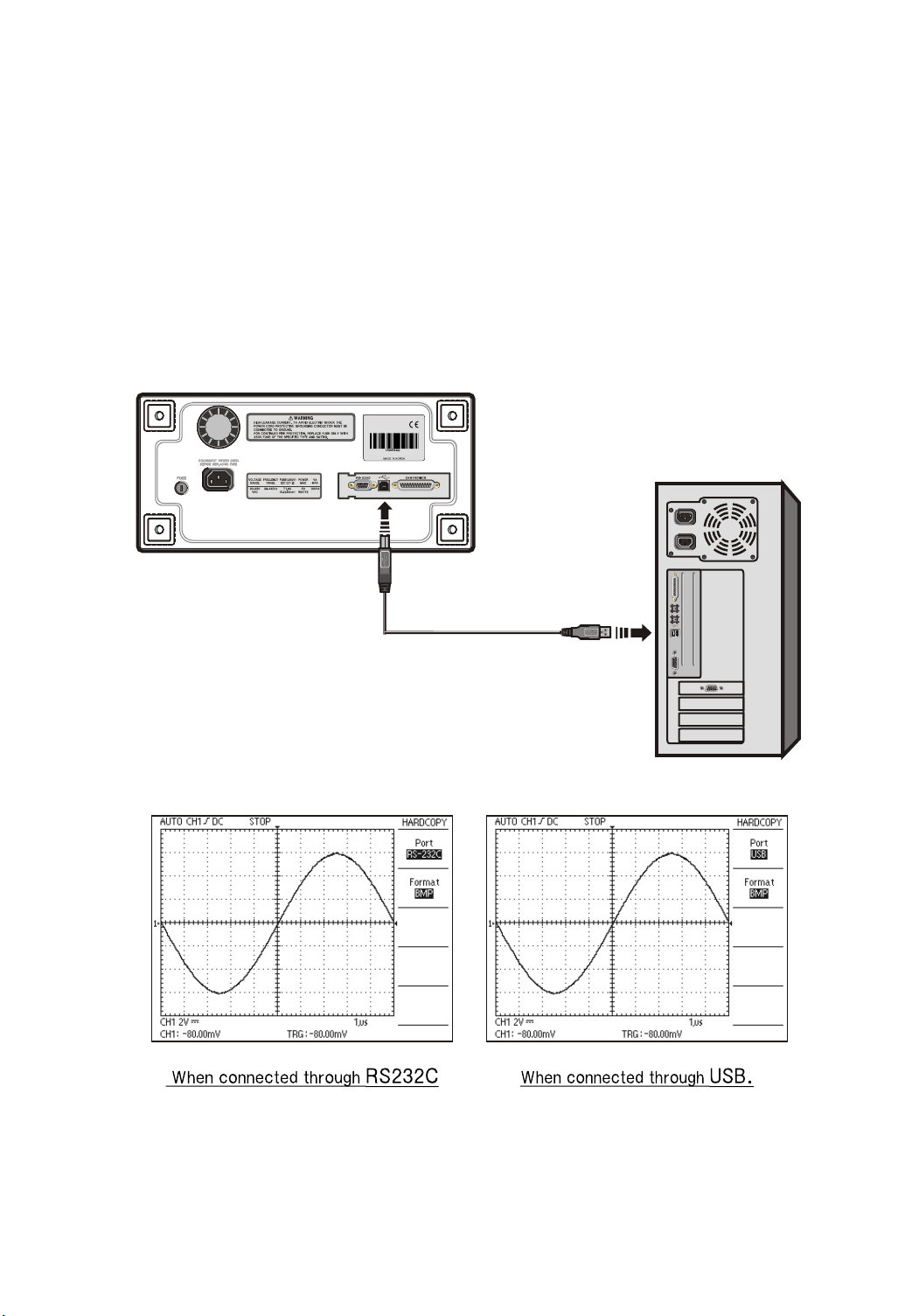
When using PC communication operation, the USB settings are as follows
Before communicating with a PC, the PC software kit (optio ) should be
installed in your PC, an interface card with USB should be installed in
your instrument. The USB protocol is spec V1.1
For more detailed information, refer to the PC software kit manual.
If users want to connect the instrument with the computer and use it, the port
needs to be set to the connection format between them and the transmission
format needs to be set to the BMP format.
d the
nal
17
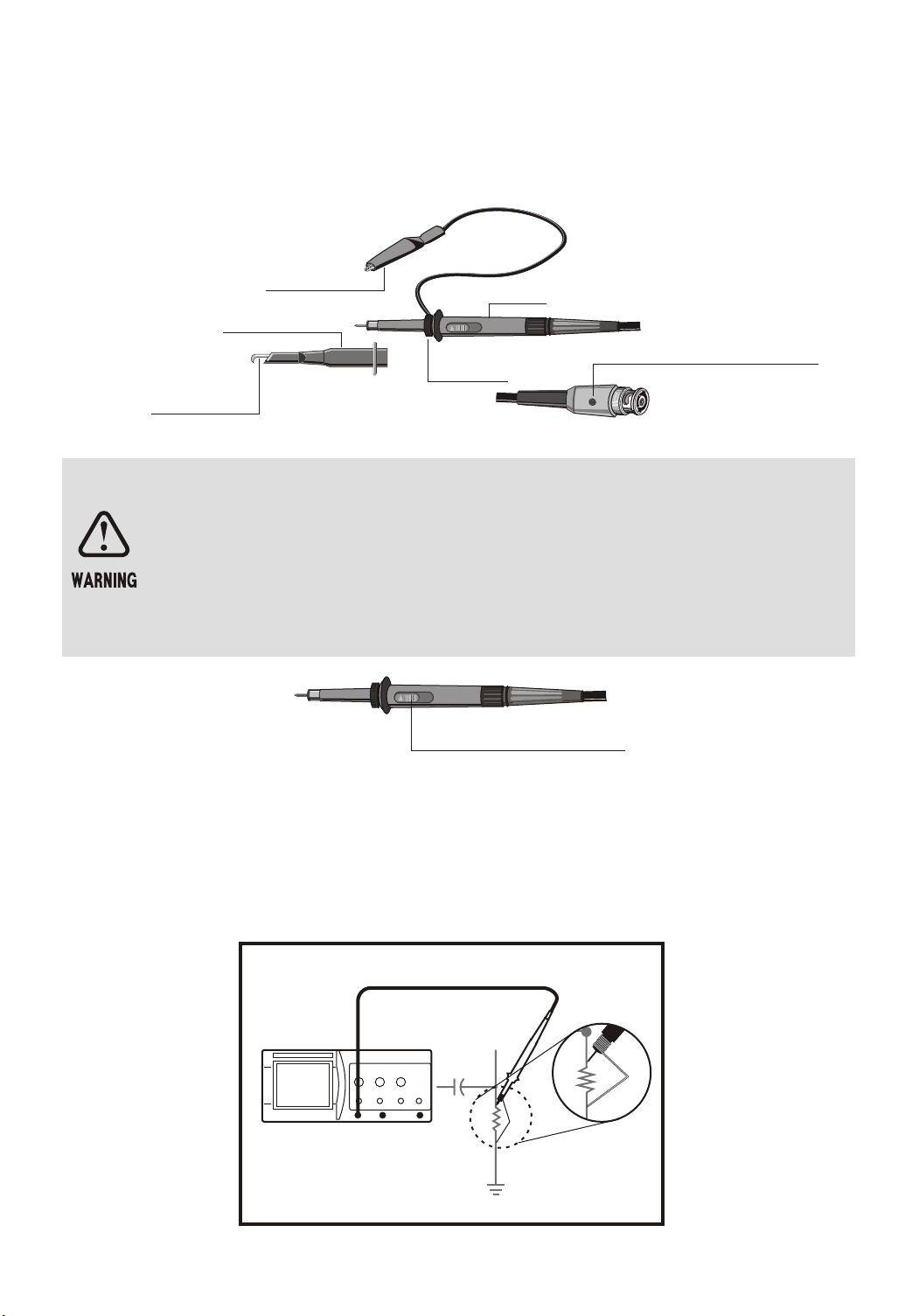
1-3-3 PROBE
The first step of measurement is to connect the signals to the instrument
properly.
GROUND CLIP
HOOK COVER
RETRACTABLE
HOOK TIP
GROUND
COVER
BODY
CAPACITANCE
CORRECTION
TRIMMER
Probe Attenuation Setting
When the optional probe is used with the x10 / x1 select switch set to x10,
the input signal to the instrument is attenuated to 1/10. When a signal is
too small to be measured with x10, use the mode x1. In this case, note
that the input impedance of x1 is different from that of x10, and the measurable frequency band becomes very low.
Attenuation switch
Probe Grounding
Connect the probe ground lead as close as possible to the point being
measured especially when measuring a signal with a fast rise time or a
high frequency signal. Long probe ground leads may cause waveform
distortions, such as ringing and overshoot.
CH 1
Spring GND
18
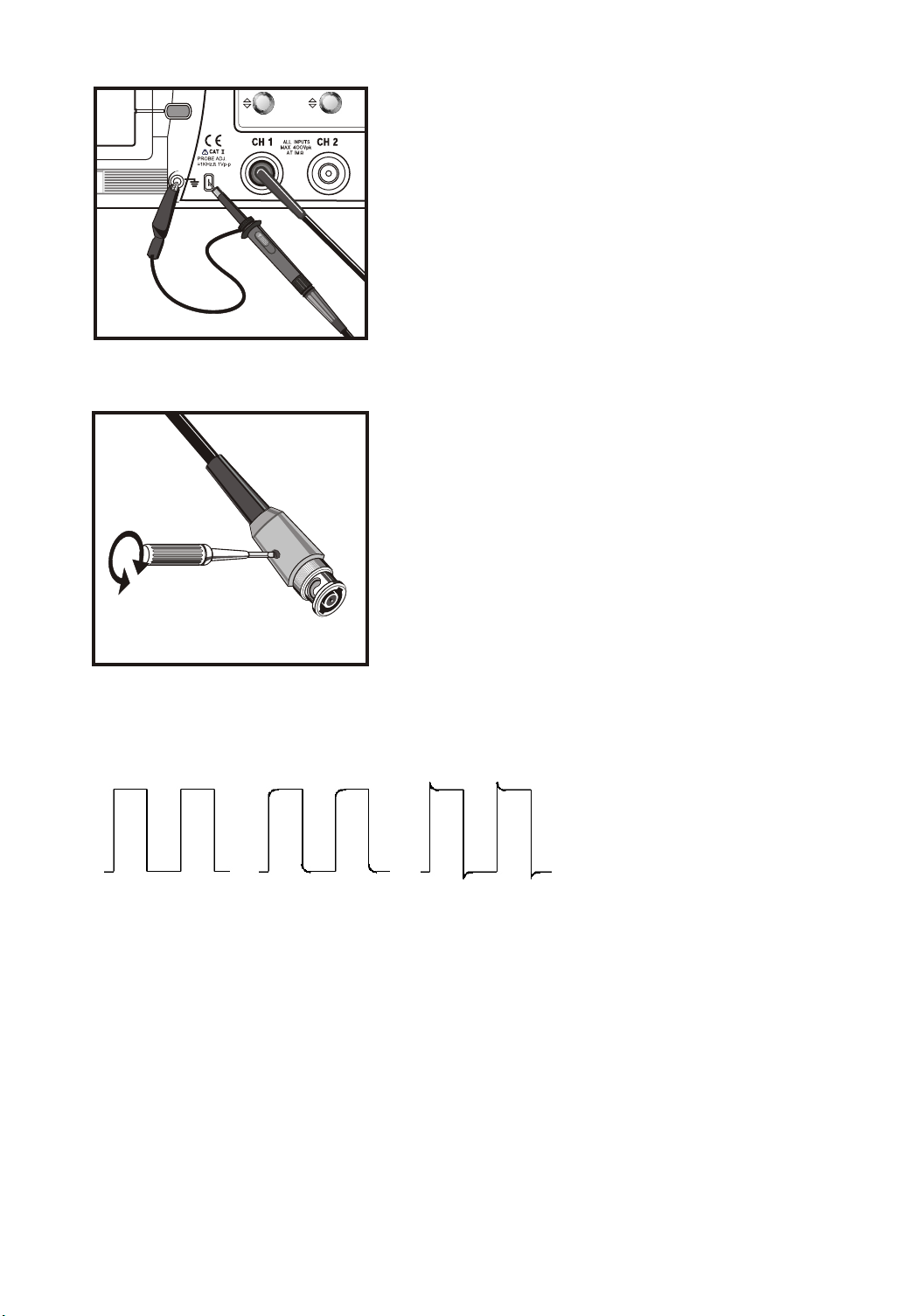
Probe Compensation
The probe switch setting is 10X.
To avoid a measurement error, probe
compensation must be done. Especially when
the probe is charged.
Connect the probe tip to the CAL 1V output
terminal. A 1 kHz square wave should be
displayed with flat tops.
Any distortion in the left presentation is
caused by incorrect probe compensation.
If overshoot or undershoot is present, turn the
screwdriver adjustment in the probe for a
flat-top presentation.
This adjustment remains in effect until changed
again.
Be sure that the attenuation switch on the
probe is set to match with the probe menu
selection in the oscilloscope.
CORRECTLY
COMPENSATED
PROBE COMPENSATION BY CORRECTION SQUARE-WAVE
UNDER
COMPENSATED
OVER
COMPENSATED
19
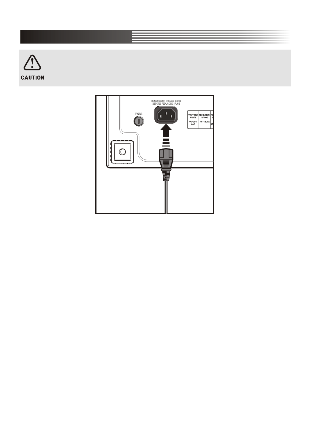
1-4 INSTALLATION
1-4-1 POWER CORD
Use only power cords designed for your oscilloscope. Use a power source
that delivers 90 to 250 VACRMS, 48 to 440 Hz.
1-4-2 INTERFACE CARD
You can increase the feature set of your oscilloscope by inserting an interface
card.
Refer to the "NOTES TO USERS" section in this manual and the PC software
Kit manual for detailed description. Install the interface card into the rear of
DS-1000 series as following procedures.
Two types of interface card (optional) are available. Be sure of which one you
need when you place an order.
20
 Loading...